EP3175146B1 - Torque reducer - Google Patents
Torque reducer Download PDFInfo
- Publication number
- EP3175146B1 EP3175146B1 EP15753964.4A EP15753964A EP3175146B1 EP 3175146 B1 EP3175146 B1 EP 3175146B1 EP 15753964 A EP15753964 A EP 15753964A EP 3175146 B1 EP3175146 B1 EP 3175146B1
- Authority
- EP
- European Patent Office
- Prior art keywords
- rollers
- screw
- housing
- axis
- actuator
- Prior art date
- Legal status (The legal status is an assumption and is not a legal conclusion. Google has not performed a legal analysis and makes no representation as to the accuracy of the status listed.)
- Active
Links
- 239000003638 chemical reducing agent Substances 0.000 title claims description 34
- 238000010079 rubber tapping Methods 0.000 claims description 6
- 238000006073 displacement reaction Methods 0.000 description 3
- 230000003134 recirculating effect Effects 0.000 description 2
- 239000000470 constituent Substances 0.000 description 1
- 238000005265 energy consumption Methods 0.000 description 1
- 238000004519 manufacturing process Methods 0.000 description 1
- 239000002184 metal Substances 0.000 description 1
- 239000002861 polymer material Substances 0.000 description 1
- 230000002787 reinforcement Effects 0.000 description 1
Images

Classifications
-
- F—MECHANICAL ENGINEERING; LIGHTING; HEATING; WEAPONS; BLASTING
- F16—ENGINEERING ELEMENTS AND UNITS; GENERAL MEASURES FOR PRODUCING AND MAINTAINING EFFECTIVE FUNCTIONING OF MACHINES OR INSTALLATIONS; THERMAL INSULATION IN GENERAL
- F16H—GEARING
- F16H25/00—Gearings comprising primarily only cams, cam-followers and screw-and-nut mechanisms
- F16H25/18—Gearings comprising primarily only cams, cam-followers and screw-and-nut mechanisms for conveying or interconverting oscillating or reciprocating motions
- F16H25/20—Screw mechanisms
- F16H25/22—Screw mechanisms with balls, rollers, or similar members between the co-operating parts; Elements essential to the use of such members
- F16H25/2247—Screw mechanisms with balls, rollers, or similar members between the co-operating parts; Elements essential to the use of such members with rollers
- F16H25/2252—Planetary rollers between nut and screw
-
- F—MECHANICAL ENGINEERING; LIGHTING; HEATING; WEAPONS; BLASTING
- F16—ENGINEERING ELEMENTS AND UNITS; GENERAL MEASURES FOR PRODUCING AND MAINTAINING EFFECTIVE FUNCTIONING OF MACHINES OR INSTALLATIONS; THERMAL INSULATION IN GENERAL
- F16D—COUPLINGS FOR TRANSMITTING ROTATION; CLUTCHES; BRAKES
- F16D2121/00—Type of actuator operation force
- F16D2121/18—Electric or magnetic
- F16D2121/24—Electric or magnetic using motors
-
- F—MECHANICAL ENGINEERING; LIGHTING; HEATING; WEAPONS; BLASTING
- F16—ENGINEERING ELEMENTS AND UNITS; GENERAL MEASURES FOR PRODUCING AND MAINTAINING EFFECTIVE FUNCTIONING OF MACHINES OR INSTALLATIONS; THERMAL INSULATION IN GENERAL
- F16D—COUPLINGS FOR TRANSMITTING ROTATION; CLUTCHES; BRAKES
- F16D2125/00—Components of actuators
- F16D2125/18—Mechanical mechanisms
- F16D2125/20—Mechanical mechanisms converting rotation to linear movement or vice versa
- F16D2125/34—Mechanical mechanisms converting rotation to linear movement or vice versa acting in the direction of the axis of rotation
- F16D2125/40—Screw-and-nut
- F16D2125/405—Screw-and-nut with differential thread
-
- F—MECHANICAL ENGINEERING; LIGHTING; HEATING; WEAPONS; BLASTING
- F16—ENGINEERING ELEMENTS AND UNITS; GENERAL MEASURES FOR PRODUCING AND MAINTAINING EFFECTIVE FUNCTIONING OF MACHINES OR INSTALLATIONS; THERMAL INSULATION IN GENERAL
- F16D—COUPLINGS FOR TRANSMITTING ROTATION; CLUTCHES; BRAKES
- F16D2125/00—Components of actuators
- F16D2125/18—Mechanical mechanisms
- F16D2125/44—Mechanical mechanisms transmitting rotation
- F16D2125/46—Rotating members in mutual engagement
- F16D2125/50—Rotating members in mutual engagement with parallel non-stationary axes, e.g. planetary gearing
-
- F—MECHANICAL ENGINEERING; LIGHTING; HEATING; WEAPONS; BLASTING
- F16—ENGINEERING ELEMENTS AND UNITS; GENERAL MEASURES FOR PRODUCING AND MAINTAINING EFFECTIVE FUNCTIONING OF MACHINES OR INSTALLATIONS; THERMAL INSULATION IN GENERAL
- F16D—COUPLINGS FOR TRANSMITTING ROTATION; CLUTCHES; BRAKES
- F16D65/00—Parts or details
- F16D65/14—Actuating mechanisms for brakes; Means for initiating operation at a predetermined position
- F16D65/16—Actuating mechanisms for brakes; Means for initiating operation at a predetermined position arranged in or on the brake
- F16D65/18—Actuating mechanisms for brakes; Means for initiating operation at a predetermined position arranged in or on the brake adapted for drawing members together, e.g. for disc brakes
-
- F—MECHANICAL ENGINEERING; LIGHTING; HEATING; WEAPONS; BLASTING
- F16—ENGINEERING ELEMENTS AND UNITS; GENERAL MEASURES FOR PRODUCING AND MAINTAINING EFFECTIVE FUNCTIONING OF MACHINES OR INSTALLATIONS; THERMAL INSULATION IN GENERAL
- F16H—GEARING
- F16H25/00—Gearings comprising primarily only cams, cam-followers and screw-and-nut mechanisms
- F16H25/18—Gearings comprising primarily only cams, cam-followers and screw-and-nut mechanisms for conveying or interconverting oscillating or reciprocating motions
- F16H25/20—Screw mechanisms
- F16H2025/2062—Arrangements for driving the actuator
- F16H2025/2075—Coaxial drive motors
Definitions
- the invention relates to the field of gearboxes and more particularly to the field of gearboxes comprising a roller screw called "satellites” or "planetary".
- Reducers employing a satellite roller screw, such as roller screws with recirculating rollers and other types of roller screws, such as inverted roller screws, are known.
- a reducer equipped with a roller screw comprises a central screw, threaded rollers and a threaded housing housing the rollers.
- the screw and the housing have threads oriented in the same direction while the rollers are provided with threads arranged perpendicularly to the axis of the screw.
- the threads of the rollers are oriented in the same direction as the threads of the screw and the housing but at a different helix angle.
- the document FR-2,839,127 discloses a reducer according to the preamble of claim 1.
- the present invention aims to provide a reducer whose reduction capabilities are improved.
- the subject of the invention is a gear unit according to claim 1.
- such a reducer makes it possible to offer an alternative to known reducers while improving their reduction capacity up to a reduction ratio of up to 1/180 without generating an increase in the size of the reducer.
- the rotation of the rollers makes it possible to drive the housing in translation in the case where the screw is fixed, or the screw in translation if the housing is fixed.
- the screw and the inner casing each comprise several threads, preferably at least three threads.
- the reducing capacity of the reducer can be further improved.
- the internal rollers are in direct contact with the screw and the inner housing.
- none of the rollers of the reducer is in direct contact with another of the rollers.
- the reducer is configured to be electrically controlled.
- the reducer eliminates the disadvantages usually encountered with the use of a hydraulic actuator.
- the invention also relates to a vehicle braking actuator comprising a gearbox according to the invention configured to actuate a service brake or a parking brake of a vehicle.
- the actuator makes it possible to produce the braking of a vehicle by implementing the gearbox according to the invention.
- the advantages of using a braking actuator equipped with such a reducer are numerous.
- the actuator no longer needs to be serviced because an actuator of this type hardly wears out.
- the braking itself only requires a low energy consumption because it is the variation of the braking which absorbs the energy here.
- Another advantage lies in the fact that the stroke of the screw relative to the housing is relatively short, which improves the accuracy of braking and allows the introduction of specific devices such as a detector on the brake pedal, or an anticollision radar.
- a gearbox according to the invention makes it possible to compensate for the wear of the brake pads and the disc because, as soon as a play appears, it can be overtaken by an appropriate displacement of the corresponding part of the gearbox.
- the actuator is configured to control a disk brake.
- the actuator comprises a floating caliper on which is rigidly fixed a brake pad.
- the invention also relates to a disk brake comprising an actuator driven by an electric motor, the actuator being in accordance with the actuator described above.
- the inner housing, the outer casing and the screw are made of a polymer material loaded with a reinforcement.
- the gearbox 10 comprises an internal screw 12, rollers 14 arranged around the screw, a cage 16 for holding the rollers and a housing 18.
- the screw 12 has three threads 12A oriented in the same first direction.
- An end 20 of the screw 12 is intended to be rigidly fixed to a rotating drive means, such as an electric motor M of the actuator for example.
- the reducer is configured to be electrically controlled.
- the other end of the screw has a free edge, smooth and hollow.
- the rollers 14 are threaded and have a longitudinal axis parallel to the X axis of the screw. They each have a single thread 14A which comes into direct contact with the threads 12A of the screw. The thread 14A of each roll 14 is oriented in a direction opposite to the threads 12A of the screw 12.
- the cage 16 holding the rollers 14 has a cylindrical shape coaxial with the screw 12 and extending over a reduced portion of the length of the screw.
- This cage 16 comprises longitudinal housings 21 configured to receive the rollers at regular intervals around the screw.
- the housings 21 comprise bores 26 opening at the ends of the cage.
- the rollers are provided with positioning pins 24 which are housed in the bores 26 of the housing 21.
- each roller 14 is held by its ends in a housing 21 of the cage 16.
- the rollers there are 10 and the cage 16 holding the rollers has ten housings, but could of course include a different number, depending on the number of rolls implemented. So, each roller 14 is rotatably mounted in its housing 21.
- the casing 18 forms a cylindrical jacket surrounding the cage 16 and arranged coaxially with the screw 12.
- the casing 18 has an internal wall provided with a thread provided with six threads 18A oriented in the same direction as that of the threads 14A of the rollers 14.
- the housing 18 comes into direct contact with the rollers.
- An end 22 of the housing 18 is configured to be rigidly attached to an element E to be moved in translation and thus guided to slide relative to the motor.
- rollers 14 are each directly engaged on the one hand with the screw 12 and on the other hand with the casing 18 by means of at least one thread 14A facing in the opposite direction of a thread 12A of the screw and in the same direction as a net 18A of the casing 18.
- the gearbox makes it possible to move the element E in a translation movement from a rotational movement of the motor M.
- the element E is for example connected to a brake pad intended to come into contact with a disk of a disk brake.
- the joint translation movement of the housing and the element E is thus greatly reduced because it results from a difference in the number of threads 12A, 14A, 18A between, on the one hand, the screw and the rollers, on the other hand , the rollers and the housing, a difference in diameter between the screw and the housing, but also the inverted direction of the threads of the screw and the rollers.
- gearbox 23 not forming part of the invention, said gearbox "double reduction stage".
- This type of gearbox 23, which is adapted to be used as a braking actuator, comprises elements substantially identical to those previously presented, namely, a screw 12 having three threads 12A, rollers 14 provided with a thread 14A oriented in the opposite direction of the threads of the screw and a housing 18 provided with six internal threads 18A oriented in the same direction as the threads of the rollers.
- the rollers are called internal rollers 14 and the housing is said internal housing 18.
- These elements are arranged relative to each other as in the previous actuator, with the difference that here the motor shaft M is fixed to the inner casing 18 instead of being fixed to the screw 12.
- the screw 12 is rigidly fixed to a housing housing the gearbox and the motor M is slidably mounted along the axis X relative to the frame.
- the reducer also comprises additional elements intended to increase the reduction capacity of such a reducer.
- these additional elements are threaded outer rollers 28 and an outer casing 30.
- the inner rollers 14 are thus arranged around the screw 12 while the outer rollers 28 are arranged peripherally to the inner housing 18 and are, like the inner rollers 14, each provided with a single thread 28A.
- the outer rollers 28 are housed in a cage (not shown) of substantially identical shape to that previously described, the diameter of which is adapted to accommodate the inner casing 18 and the outer rollers 28.
- the outer casing 30 surrounds the cage and has a cylindrical shape coaxial with the screw 12.
- the outer casing 30 has a tapping provided with six threads 30A on its inner wall.
- An element E intended to be displaced in translation is rigidly fixed to an end 32 of the outer casing 30, which rotation is prohibited.
- the outer rollers 28 each engage directly with the outer housing 30 and the inner housing 18.
- the thread 28A of each outer roller 28 is oriented in the opposite direction of the threads 18B of the inner housing 18 and in the same direction as the threads of the outer casing 30.
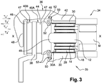
- the gear unit is an electromechanical brake actuator 34 of an integral vehicle of a brake device 35 of the disc brake type.
- a braking device 35 comprises said actuator 34, a brake disk 38, brake pads 40A, 40B and a floating caliper 36.
- the floating stirrup 36 has an attachment portion 42, a disc passage 44 and a support jaw 48.
- the end of the floating stirrup comprising the attachment portion 42 is rigidly fixed to the outer casing 30 of the gearbox of the actuator 34.
- the other end of the floating stirrup comprises the support jaw 48, which is extends parallel to the disk 38 and carries one of the platelets 40B.
- the disk passage 44 forms a housing for the disk 38 and the platelets 40A, 40B.
- the brake pads 40A, 40B are disposed laterally, on either side of the disc 38 and each comprise a metal support 46 covered with a lining 47.
- a deformable circular seal 50 is disposed around the inner pad and connects an edge of the inner pad to an edge of the outer casing.
- the plates, the yoke and the casing each comprise a housing 52 adapted to accommodate attachment portions of the seal. This seal is intended to isolate the actuator from any external pollution.
- the actuator 34 comprises a so-called double-reduction gearbox of design substantially similar to that of the gearbox described above.
- the constituent elements are thus arranged as above, with the difference that in this embodiment the screw 12 is configured to translate parallel to the X axis, so that the screw forms a piston whose end connected to the wafer brake is adapted to come into contact with the brake disc 38.
- the inner casing 18 driven by the motor is fixed in translation.
- the inner casing 18 rotates.
- the internal rollers 14, which are in direct contact with the inner casing 18, are rotated around their own axis and around the X axis of the screw 12. They are also moved in a translational movement T1 'parallel to the axis X.
- the rotation of the internal rollers 18 thus causes a translation T2 'of the screw 12 along the axis X, in a positive direction, so that the end 49 of the screw moves the inner brake pad 40A and pushes the against the brake disc 38 to generate a part of the braking of the vehicle.
- the rotation of the inner casing 18 causes the outer rollers 28 to rotate about their own axis and around the X axis. Also, the outer rollers evolve in a translation movement T3 'parallel to the X axis.
- the rotation of the outer rollers 28 drives the outer casing 30 in a translation movement T4 'parallel to the axis X, in a negative direction, thereby generating a translational movement of the yoke in the negative direction.
- the outer plate 40B therefore comes into contact with the brake disc 38, thus generating another part of the braking of the vehicle.
- the disc 38 is pressed between the two plates 40A, 40B.
- the invention is not limited to the embodiment shown and other embodiments will become apparent to those skilled in the art. It is in particular possible to provide, as a variant of the gearbox of the figure 1 , that the electric motor is connected to the housing 18, and that it is the screw 12 which is moved in translation and changes the element E.
- the reducer of the figure 2 has an outer casing 30 which is fixed and that it is the screw 12 which is moved in translation while carrying the element E.
- the motor is not fixed to the inner casing, but that it directly drives one of the two housings housing the rotating rollers.
- gearbox according to the invention is applicable to other areas than braking.
Description
L'invention se rapporte au domaine des réducteurs et plus particulièrement au domaine des réducteurs comprenant une vis à rouleaux dits « satellites » ou « planétaires ».The invention relates to the field of gearboxes and more particularly to the field of gearboxes comprising a roller screw called "satellites" or "planetary".
On connait des réducteurs mettant en oeuvre une vis à rouleaux satellites, telles que les vis à rouleaux avec recirculation des rouleaux et d'autres types de vis à rouleaux, comme les vis à rouleaux inversés notamment.Reducers employing a satellite roller screw, such as roller screws with recirculating rollers and other types of roller screws, such as inverted roller screws, are known.
De manière classique, un réducteur muni d'une vis à rouleaux comprend une vis centrale, des rouleaux filetés et un carter taraudé logeant les rouleaux. Dans le cas d'une vis à recirculation de rouleaux, la vis et le carter ont des filets orientés dans le même sens tandis que les rouleaux sont munis de filets agencés perpendiculairement à l'axe de la vis. Pour les vis à rouleaux inversés, les filets des rouleaux sont orientés dans le même sens que les filets de la vis et du carter mais selon un angle d'hélice différent.Conventionally, a reducer equipped with a roller screw comprises a central screw, threaded rollers and a threaded housing housing the rollers. In the case of a screw recirculating rollers, the screw and the housing have threads oriented in the same direction while the rollers are provided with threads arranged perpendicularly to the axis of the screw. For inverted roller screws, the threads of the rollers are oriented in the same direction as the threads of the screw and the housing but at a different helix angle.
Il est envisageable de prévoir un réducteur du type précité dans un actionneur électromécanique de freinage d'un véhicule. Toutefois cela augmente le coût de fabrication d'un tel actionneur. En effet, il est particulièrement difficile de coupler un moteur électrique bon marché à un réducteur du type précité car la vitesse de rotation des moteurs bon marché est généralement très élevée. En fait, les réducteurs de l'état de la technique munis d'une vis à rouleaux ont une capacité de réduction qui n'est pas suffisante pour pouvoir être couplés avec un moteur électrique à très haute vitesse de rotation. L'utilisation des réducteurs de l'état de la technique nécessite donc l'emploi de moteurs électriques dont la vitesse est moindre, mais dont le prix de revient est plus élevé.It is conceivable to provide a reducer of the aforementioned type in an electromechanical brake actuator of a vehicle. However, this increases the manufacturing cost of such an actuator. Indeed, it is particularly difficult to couple a cheap electric motor to a reducer of the aforementioned type because the rotational speed of inexpensive engines is generally very high. In fact, prior art reducers equipped with a roller screw have a reduction capacity which is not sufficient to be coupled with an electric motor at a very high speed of rotation. The use of reducers of the state of the art therefore requires the use of electric motors whose speed is lower, but whose cost is higher.
Le document
La présente invention vise à proposer un réducteur dont les capacités de réduction sont améliorées.The present invention aims to provide a reducer whose reduction capabilities are improved.
A cet effet, l'invention a pour objet un réducteur selon la revendication 1.For this purpose, the subject of the invention is a gear unit according to claim 1.
Ainsi, un tel réducteur permet d'offrir une alternative aux réducteurs connus tout en améliorant leur capacité de réduction jusqu'à un rapport de réduction pouvant atteindre 1/180 sans générer d'augmentation de l'encombrement du réducteur. De plus, la rotation des rouleaux permet d'entraîner le carter en translation dans le cas où la vis est fixe, ou bien la vis en translation si c'est le carter qui est fixe.Thus, such a reducer makes it possible to offer an alternative to known reducers while improving their reduction capacity up to a reduction ratio of up to 1/180 without generating an increase in the size of the reducer. In addition, the rotation of the rollers makes it possible to drive the housing in translation in the case where the screw is fixed, or the screw in translation if the housing is fixed.
De plus, pour ce type de réducteur, dit à « double étage de réduction », l'orientation dans le même sens des filets des rouleaux externes en prise avec ceux du carter externe offre une alternative aux réducteurs comportant des rouleaux externes dont les filets seraient orientés dans le même sens que celui des filets des carters interne et externe. Par ailleurs, un tel réducteur possède une capacité de réduction améliorée par rapport aux réducteurs à double étages de réduction connus.In addition, for this type of gearbox, said to "double reduction stage", the orientation in the same direction of the threads of the outer rollers engaged with those of the crankcase external offers an alternative to gearboxes with external rollers whose threads are oriented in the same direction as the threads of the inner and outer casings. Furthermore, such a reducer has an improved reduction capacity compared to known double reduction stage reducers.
Avantageusement, la vis et le carter interne comportent chacun plusieurs filets, de préférence au moins trois filets.Advantageously, the screw and the inner casing each comprise several threads, preferably at least three threads.
Ainsi, la capacité de réduction du réducteur peut être encore améliorée.Thus, the reducing capacity of the reducer can be further improved.
De préférence les rouleaux internes sont en prise directe avec la vis et le carter interne.Preferably the internal rollers are in direct contact with the screw and the inner housing.
De préférence encore, aucun des rouleaux du réducteur n'est en prise directe avec un autre des rouleaux.More preferably, none of the rollers of the reducer is in direct contact with another of the rollers.
Par exemple, le réducteur est configuré pour être commandé électriquement.For example, the reducer is configured to be electrically controlled.
Ainsi, le réducteur permet de supprimer les inconvénients rencontrés habituellement avec l'utilisation d'un actionneur hydraulique.Thus, the reducer eliminates the disadvantages usually encountered with the use of a hydraulic actuator.
L'invention a également pour objet un actionneur de freinage de véhicule comportant un réducteur selon l'invention configuré pour actionner un frein de service ou un frein de parking d'un véhicule.The invention also relates to a vehicle braking actuator comprising a gearbox according to the invention configured to actuate a service brake or a parking brake of a vehicle.
Ainsi, l'actionneur permet de produire le freinage d'un véhicule en mettant en oeuvre le réducteur selon l'invention. Les avantages liés à l'utilisation d'un actionneur de freinage muni d'un tel réducteur sont nombreux. Par exemple, l'actionneur n'a plus besoin de faire l'objet d'une maintenance car un actionneur de ce type ne s'use pratiquement pas. On comprend que, grâce à la capacité de réduction élevée du réducteur qui équipe cet actionneur de freinage, il devient possible d'utiliser un moteur électrique dont la vitesse de rotation est élevée et dont le coût est faible. Par ailleurs, le freinage lui-même ne nécessite qu'une faible consommation d'énergie car c'est la variation du freinage qui absorbe ici l'énergie. Un autre avantage réside dans le fait que la course de la vis par rapport au carter est relativement courte, ce qui améliore la précision du freinage et autorise la mise en place de dispositifs spécifiques comme par exemple un détecteur sur la pédale de frein, ou encore un radar anticollision.Thus, the actuator makes it possible to produce the braking of a vehicle by implementing the gearbox according to the invention. The advantages of using a braking actuator equipped with such a reducer are numerous. For example, the actuator no longer needs to be serviced because an actuator of this type hardly wears out. It is understood that, thanks to the high reduction capacity of the reducer that equips the braking actuator, it becomes possible to use an electric motor whose rotation speed is high and the cost is low. Moreover, the braking itself only requires a low energy consumption because it is the variation of the braking which absorbs the energy here. Another advantage lies in the fact that the stroke of the screw relative to the housing is relatively short, which improves the accuracy of braking and allows the introduction of specific devices such as a detector on the brake pedal, or an anticollision radar.
Également, un réducteur selon l'invention permet de compenser l'usure des plaquettes de freins et du disque car dès l'apparition d'un jeu, celui-ci peut être rattrapé par un déplacement approprié de la pièce correspondante du réducteur.Also, a gearbox according to the invention makes it possible to compensate for the wear of the brake pads and the disc because, as soon as a play appears, it can be overtaken by an appropriate displacement of the corresponding part of the gearbox.
Avantageusement, l'actionneur est configuré pour commander un frein à disque.Advantageously, the actuator is configured to control a disk brake.
On peut prévoir que l'actionneur comprend un étrier flottant sur lequel est rigidement fixée une plaquette de frein.It can be provided that the actuator comprises a floating caliper on which is rigidly fixed a brake pad.
Ainsi, immédiatement après le freinage, la plaquette s'éloignera du disque conjointement avec l'étrier, ce qui permet d'éviter tout couple de freinage résiduel non désiré.Thus, immediately after braking, the plate will move away from the disc together with the caliper, which makes it possible to avoid any residual braking torque longed for.
L'invention a également pour objet un frein à disque comportant un actionneur entraîné par un moteur électrique, l'actionneur étant conforme à l'actionneur décrit précédemment.The invention also relates to a disk brake comprising an actuator driven by an electric motor, the actuator being in accordance with the actuator described above.
Enfin, on peut également prévoir que le carter interne, le carter externe et la vis sont fabriqués en un matériau polymère chargé d'un renfort.Finally, it is also possible that the inner housing, the outer casing and the screw are made of a polymer material loaded with a reinforcement.
Nous allons maintenant décrire deux actionneurs ne faisant pas partie de l'invention et un mode de réalisation de l'invention à titre d'exemples non limitatifs en référence aux dessins annexés sur lesquels :
- la
figure 1 est une vue en perspective d'un actionneur ne faisant pas partie de l'invention dans lequel le carter est représenté en coupe ; - la
figure 2 est une vue en coupe d'un actionneur ne faisant pas partie de l'invention et ; - la
figure 3 est une vue en coupe d'un actionneur de freinage formant un mode de réalisation de l'invention.
- the
figure 1 is a perspective view of an actuator not forming part of the invention in which the housing is shown in section; - the
figure 2 is a sectional view of an actuator not forming part of the invention and; - the
figure 3 is a sectional view of a braking actuator forming an embodiment of the invention.
En référence à la
La vis 12 présente trois filets 12A orientés selon un même premier sens. Une extrémité 20 de la vis 12 est destinée à être rigidement fixée à un moyen d'entrainement en rotation, tel qu'un moteur électrique M de l'actionneur par exemple. Ainsi, le réducteur est configuré pour être commandé électriquement. L'autre extrémité de la vis comporte un bord libre, lisse et creux.The
Les rouleaux 14 sont filetés et ont un axe longitudinal parallèle à l'axe X de la vis. Ils présentent chacun un unique filet 14A qui vient en prise directe avec les filets 12A de la vis. Le filet 14A de chaque rouleau 14 est orienté selon un sens inverse des filets 12A de la vis 12.The
La cage 16 de maintien des rouleaux 14 présente une forme cylindrique coaxiale à la vis 12 et s'étendant sur une portion réduite de la longueur de la vis. Cette cage 16 comporte des logements longitudinaux 21 configurés pour accueillir les rouleaux à intervalles réguliers autour de la vis. A cet effet, les logements 21 comportent des alésages 26 débouchant aux extrémités de la cage. A leurs extrémités, les rouleaux sont munis de pions de positionnement 24 qui viennent se loger dans les alésages 26 des logements 21. Ainsi, chaque rouleau 14 est maintenu par ses extrémités dans un logement 21 de la cage 16. Dans cet exemple, les rouleaux sont au nombre de 10 et la cage 16 de maintien des rouleaux comporte dix logements, mais pourrait bien sûr en comporter un nombre différent, en fonction du nombre de rouleaux mis en oeuvre. Ainsi, chaque rouleau 14 est monté mobile à rotation dans son logement 21.The
Le carter 18 forme une chemise cylindrique entourant la cage 16 et agencée coaxialement avec la vis 12. Le carter 18 comporte une paroi interne pourvue d'un taraudage muni de six filets 18A orientés dans le même sens que celui des filets 14A des rouleaux 14. Le carter 18 vient en prise directe avec les rouleaux. Une extrémité 22 du carter 18 est configurée pour être fixée rigidement à un élément E destiné à être déplacé en translation et ainsi guidé à coulissement par rapport au moteur.The
Ainsi, les rouleaux 14 sont chacun en prise directe d'une part avec la vis 12 et d'autre part avec le carter 18 au moyen d'au moins un filet 14A orienté en sens inverse d'un filet 12A de la vis et dans le même sens qu'un filet 18A du carter 18.Thus, the
Nous allons maintenant présenter le fonctionnement du réducteur 10. On suppose que le réducteur 10 est entraîné en rotation par un arbre d'un moteur électrique M de type « brushless » apte à tourner dans les deux sens de rotation. Lorsque le moteur électrique M est actionné selon un premier sens de rotation, la vis 12 entraîne les rouleaux 14 et la cage 16 en rotation autour de l'axe X. Comme les rouleaux 14 sont en prise avec le carter 18, leur mouvement de rotation génère un mouvement de translation du carter 18 selon l'axe X de la vis.We will now present the operation of the
En d'autres termes, il existe un déplacement axial selon l'axe X entre la vis 12 et les rouleaux 14, entre les rouleaux 14 et le carter 18, et entre le carter 18 et la vis 12. Ainsi, le réducteur permet de déplacer l'élément E selon un mouvement de translation à partir d'un mouvement de rotation du moteur M. L'élément E est par exemple relié à une plaquette de frein destinée à venir en contact avec un disque d'un frein à disque.In other words, there is an axial displacement along the axis X between the
Le mouvement de translation conjoint du carter et de l'élément E est ainsi fortement réduit car il résulte d'une différence du nombre de filets 12A, 14A, 18A entre, d'une part, la vis et les rouleaux, d'autre part, les rouleaux et le carter, d'une différence de diamètre entre la vis et le carter, mais également du sens inversé des filets de la vis et des rouleaux.The joint translation movement of the housing and the element E is thus greatly reduced because it results from a difference in the number of
Dans le cas d'une rotation du moteur M dans le sens inverse, on comprend que les mouvements de rotation et de translation décrits ci-dessus sont inversés, générant ainsi un mouvement de translation de l'élément E dans le sens inverse.In the case of a rotation of the motor M in the opposite direction, it is understood that the rotational and translational movements described above are reversed, thereby generating a translational movement of the element E in the opposite direction.
On va maintenant décrire ci-dessous des actionneurs, en se référant aux
En référence à la
Le réducteur comporte également des éléments supplémentaires destinés à augmenter la capacité de réduction d'un tel réducteur. En l'occurrence, ces éléments supplémentaires sont des rouleaux externes filetés 28 et un carter externe 30.The reducer also comprises additional elements intended to increase the reduction capacity of such a reducer. In this case, these additional elements are threaded
Les rouleaux internes 14 sont donc agencés autour de la vis 12 tandis que les rouleaux externes 28 sont agencés périphériquement au carter interne 18 et sont, tout comme les rouleaux internes 14, chacun munis d'un seul filet 28A. Les rouleaux externes 28 sont logés dans une cage (non représentée) de forme sensiblement identique à celle précédemment décrite dont le diamètre est adapté pour accueillir le carter interne 18 et les rouleaux externes 28.The
Le carter externe 30 entoure la cage et a une forme cylindrique coaxiale avec la vis 12. Le carter externe 30 comporte un taraudage pourvu de six filets 30A sur sa paroi interne. Un élément E destiné à être déplacé en translation est rigidement fixé à une extrémité 32 du carter externe 30 dont toute rotation est interdite.The
Les rouleaux externes 28 viennent chacun en prise directe avec le carter externe 30 et avec le carter interne 18. Le filet 28A de chaque rouleau externe 28 est orienté en sens inverse des filets 18B du carter interne 18 et dans le même sens que les filets du carter externe 30.The
Nous allons maintenant présenter le fonctionnement du réducteur 23. Lorsque le moteur électrique M est actionné selon un premier sens de rotation, les rouleaux internes 14, qui sont en prise directe avec le carter interne 18, sont entraînés en rotation autour de l'axe X de la vis et également en rotation sur eux-mêmes selon leurs axes propres. Ces mouvements de rotation génèrent un déplacement en translation de la cage et des rouleaux selon un mouvement de translation T1 parallèle à l'axe X. Comme les rouleaux internes 14 se déplacent en translation sur la vis 12 qui est fixe, le carter interne 18 et l'arbre du moteur M sont entraînés par les rouleaux internes 14 selon un mouvement de translation T2 parallèle à l'axe X.We will now present the operation of the
Concernant les rouleaux externes 28, ceux-ci sont entraînés en rotation par le carter interne 18, et évoluent selon un mouvement de translation T3 parallèle à l'axe X.Concerning the
Enfin, la rotation des rouleaux externes 28 entraîne le carter externe selon un mouvement de translation T4 parallèle à l'axe X.Finally, the rotation of the
En référence à la
L'étrier flottant 36 comporte une partie d'attache 42, un passage de disque 44 et un mors d'appui 48.The floating
L'extrémité de l'étrier flottant comportant la partie d'attache 42 est rigidement fixée au carter externe 30 du réducteur de l'actionneur 34. L'autre extrémité de l'étrier flottant comporte le mors d'appui 48, lequel s'étend parallèlement au disque 38 et porte une des plaquettes 40B. Entre les deux extrémités de l'étrier flottant 36, le passage de disque 44 forme un logement pour le disque 38 et les plaquettes 40A, 40B.The end of the floating stirrup comprising the
De manière classique, les plaquettes de freins 40A, 40B sont disposées latéralement, de part et d'autre du disque 38 et comportent chacune un support métallique 46 recouvert d'une garniture 47. On distingue la plaquette de frein intérieure 40A dont le support 46 est rigidement fixé à une extrémité 49 de la vis 12, et la plaquette extérieure 40B dont le support 46 est rigidement fixé au mors d'appui de l'étrier. Un joint d'étanchéité circulaire déformable 50 est disposé autour de la plaquette intérieure et relie un bord de la plaquette de frein intérieure à un bord du carter externe. A cet effet, les plaquettes, l'étrier et le carter comportent chacun un logement 52 adapté pour accueillir des parties d'attache du joint. Ce joint est destiné à isoler l'actionneur de toute pollution extérieure.Conventionally, the
L'actionneur 34 comporte un réducteur dit à double étage de réduction de conception sensiblement semblable à celui du réducteur décrit précédemment. Les éléments constitutifs sont donc agencés comme précédemment, à la différence près que dans ce mode de réalisation la vis 12 est configurée pour translater parallèlement à l'axe X, de telle sorte que la vis forme un piston dont l'extrémité reliée à la plaquette de frein est adaptée pour venir au contact du disque de frein 38. Dans cet exemple, le carter interne 18 entraîné par le moteur est fixe en translation.The
On va maintenant décrire le fonctionnement de l'actionneur de freinage 34 utilisé dans le dispositif de freinage 35 ci-dessus.We will now describe the operation of the
Lorsque le moteur électrique M est actionné selon un premier sens de rotation, le carter interne 18 entre en rotation. Les rouleaux internes 14, qui sont en prise directe avec le carter interne 18, sont entraînés en rotation autour de leur axe propre et, autour de l'axe X de la vis 12. Ils sont également déplacés selon un mouvement de translation T1' parallèle à l'axe X.When the electric motor M is actuated in a first direction of rotation, the
La rotation des rouleaux internes 18 entraine ainsi une translation T2' de la vis 12 selon l'axe X, dans un sens dit positif, de telle sorte que l'extrémité 49 de la vis déplace la plaquette de frein intérieure 40A et pousse celle-ci contre le disque de frein 38 pour générer une partie du freinage du véhicule.The rotation of the
Par ailleurs, la rotation du carter interne 18 entraine les rouleaux externes 28 en rotation autour de leur axe propre et autour de l'axe X. Aussi, les rouleaux externes évoluent selon un mouvement de translation T3' parallèle à l'axe X.Furthermore, the rotation of the
Enfin, la rotation des rouleaux externes 28 entraîne le carter externe 30 selon un mouvement de translation T4' parallèle à l'axe X, dans un sens dit négatif, générant ainsi un déplacement en translation de l'étrier dans le sens négatif. La plaquette externe 40B vient donc en contact avec le disque de frein 38, générant ainsi une autre partie du freinage du véhicule. Le disque 38 est donc pressé entre les deux plaquettes 40A, 40B.Finally, the rotation of the
On comprend que lorsque l'arbre du moteur électrique M tourne dans l'autre sens, les mouvements de rotation et de translation décrits ci-avant sont inversés et que les plaquettes de frein translatent parallèlement à l'axe X en s'éloignant du disque de frein.It will be understood that when the shaft of the electric motor M rotates in the other direction, the rotational and translational movements described above are reversed and that the brake pads translate parallel to the X axis away from the disk. of brake.
L'invention n'est pas limitée au mode de réalisation présenté et d'autres modes de réalisation apparaîtront clairement à l'homme du métier. Il est notamment possible de prévoir, en variante du réducteur de la
En variante, on peut aussi prévoir que le réducteur de la
Également, en variante du mode de réalisation, on peut prévoir que le moteur n'est pas fixé au carter interne, mais qu'il entraîne directement une des deux cages de logement des rouleaux en rotation.Also, as a variant of the embodiment, it can be provided that the motor is not fixed to the inner casing, but that it directly drives one of the two housings housing the rotating rollers.
Enfin, on précise que le réducteur selon l'invention est applicable à d'autres domaines que le freinage.Finally, it is specified that the gearbox according to the invention is applicable to other areas than braking.
- 10 : réducteur10: reducer
- 12: vis12: screws
- 12A : filets de la vis12A: threads of the screw
- 14 : rouleaux ; rouleaux internes14: rollers; internal rollers
- 14 A : filet d'un rouleau ; filet d'un rouleau interne14A: net of a roll; net of an internal roller
- 16 : cage16: cage
- 18 : carter ; carter interne18: crankcase; internal housing
- 18 A : filets du taraudage du carter ; filets du taraudage du carter interne18 A: threads of the tapping of the housing; inner casing threads
- 18 B : filets sur paroi externe du carter interne18 B: threads on outer wall of inner casing
- 20 : extrémité de la vis20: end of the screw
- 21 : logements21: housing
- 22 : extrémité du carter22: end of the housing
- 23 : réducteur dit « à double étage de réduction »23: gearbox says "double-stage reduction"
- 24 : pions de positionnement24: positioning pawns
- 26 : alésages26: bores
- 28 : rouleaux externes28: external rollers
- 28 A : filet d'un rouleau externe28 A: net of an outer roll
- 30 : carter externe30: outer casing
- 30 A : filets du taraudage du carter externe30 A: Tapping threads of the outer casing
- 32 : extrémité du carter externe32: end of the outer casing
- 34 : actionneur de freinage34: brake actuator
- 35 : dispositif de freinage35: braking device
- 36 : étrier flottant36: floating stirrup
- 38 : disque de frein38: brake disc
- 40 : plaquettes de frein40: brake pads
- 42 : partie d'attache42: attachment part
- 44 : passage de disque44: record passage
- 46 : support46: support
- 47 : garniture47: filling
- 49 : extrémité de la vis49: end of the screw
- 50 : joint d'étanchéité50: seal
- 52 : logement52: housing
- T1 : mouvement de translation des rouleaux internesT1: translation movement of the internal rollers
- T2 : mouvement de translation du carter interneT2: translation movement of the internal casing
- T3 : mouvement de translation des rouleaux externesT3: translation movement of the outer rollers
- T4 : mouvement de translation du carter externeT4: translation movement of the outer casing
- T1' : mouvement de translation des rouleaux internesT1 ': translation movement of the internal rollers
- T2' : mouvement de translation de la visT2 ': translation movement of the screw
- T3' : mouvement de translation des rouleaux externesT3 ': translation movement of the outer rollers
- T4' : mouvement de translation du carter externeT4 ': translation movement of the outer casing
- E : élément destiné à être déplacé en translationE: element intended to be displaced in translation
- M : moteur électriqueM: electric motor
- X : axe de la visX: axis of the screw
Claims (9)
- Reducer comprising- a frame,- a screw (12) having a longitudinal axis X,- threaded inner rollers (14), and- a tapped and threaded inner housing (18),the inner rollers (14) being each engaged firstly with the screw (12) and secondly with the inner housing (18) via at least one thread (14A) directed in the opposite direction of a thread (12A) of the screw (12) and in the same direction as a thread (18A) of the tapping in the inner housing, the reducer further comprising- a tapped outer housing (30),- outer rollers (28) each engaged firstly with the inner housing (18) and secondly with the outer housing (30), the outer rollers (28) being provided with at least one thread (28A) directed in the opposite direction of a thread (18B) of the thread of the inner housing (18) and in the same direction as a thread (30A) of the tapping in the outer housing (30);characterised in that the inner housing (18) is fixed in translation relative to the frame, the reducer being arranged such that when the inner housing (18) rotates about the axis X, it drives a rotation about the axis X of the inner rollers (14) translating the screw (12) relative to the frame along the axis X in a first direction, and a rotation of the outer rollers (28) about the axis X driving the outer housing (30) along a translation movement relative to the frame parallel to the axis X, in a second direction opposite to the first direction, the rotation of the inner housing (18) about the axis X also driving the inner rollers (14) in rotation about their own axes and along a translation movement relative to the frame parallel to the axis X, and the outer rollers (28) in rotation about their own axes and along a translation movement relative to the frame parallel to the axis X.
- Reducer according to the preceding claim, wherein the screws (12) and the tapping of the inner housing (18) each comprise several threads, preferably at least three threads (12A, 18A).
- Reducer according to at least any one of the preceding claims, wherein the inner rollers (14) are engaged directly with the screw (12) and the inner housing (18).
- Reducer according to at least any one of claims 1 to 3, wherein none of the rollers (14, 28) is engaged directly with another one of the rollers (14, 28).
- Reducer according to at least any one of the preceding claims, configured to be controlled electrically.
- Vehicle braking actuator (34) comprising a reducer according to at least any one of claims 1 to 5, and configured to actuate a vehicle service brake or parking brake.
- Actuator (34) according to claim 6, configured to control a disc brake.
- Actuator (34) according to claim 7, comprising a floating calliper (36) to which a brake pad (40B) is rigidly attached.
- Disc brake comprising an actuator (34) driven by an electric motor, the actuator being according to one of claims 6 to 8.
Applications Claiming Priority (2)
| Application Number | Priority Date | Filing Date | Title |
|---|---|---|---|
| FR1457381A FR3024516B1 (en) | 2014-07-30 | 2014-07-30 | TORQUE REDUCER |
| PCT/FR2015/051990 WO2016016542A1 (en) | 2014-07-30 | 2015-07-20 | Torque reducer |
Publications (2)
| Publication Number | Publication Date |
|---|---|
| EP3175146A1 EP3175146A1 (en) | 2017-06-07 |
| EP3175146B1 true EP3175146B1 (en) | 2019-08-28 |
Family
ID=51688288
Family Applications (1)
| Application Number | Title | Priority Date | Filing Date |
|---|---|---|---|
| EP15753964.4A Active EP3175146B1 (en) | 2014-07-30 | 2015-07-20 | Torque reducer |
Country Status (6)
| Country | Link |
|---|---|
| US (1) | US10393245B2 (en) |
| EP (1) | EP3175146B1 (en) |
| JP (1) | JP6620141B2 (en) |
| CN (1) | CN106536985A (en) |
| FR (1) | FR3024516B1 (en) |
| WO (1) | WO2016016542A1 (en) |
Families Citing this family (7)
| Publication number | Priority date | Publication date | Assignee | Title |
|---|---|---|---|---|
| FR3024513B1 (en) * | 2014-07-30 | 2018-01-19 | Chassis Brakes International B.V. | BRAKE ACTUATOR FOR VEHICLE |
| CN109219544B (en) * | 2016-06-28 | 2021-04-23 | 日立汽车系统株式会社 | Disc brake |
| CN106838172A (en) * | 2017-04-10 | 2017-06-13 | 长江大学 | A kind of mud motor spiral steel ball reducer |
| FR3088697B1 (en) | 2018-11-21 | 2021-06-25 | Foundation Brakes France | DISC BRAKE PROVIDING A BALANCED DISTRIBUTION OF THE THRUST EFFORTS APPLIED BY A PISTON ON AT LEAST ONE BRAKE PAD |
| EP3663612B1 (en) * | 2018-12-05 | 2022-06-01 | Ewellix AB | Actuation mechanism with a satellite roller screw mechanism |
| US11333229B2 (en) * | 2020-03-17 | 2022-05-17 | ZF Active Safety US Inc. | Roller screw system |
| FR3123955B1 (en) | 2021-06-15 | 2023-11-17 | Hitachi Astemo France | DISC BRAKE INCORPORATING AN ELECTROMECHANICAL PARKING BRAKE |
Family Cites Families (11)
| Publication number | Priority date | Publication date | Assignee | Title |
|---|---|---|---|---|
| US3406584A (en) * | 1967-08-21 | 1968-10-22 | Roantree Electro Mech Corp | Differential roller nut |
| JPH08296674A (en) | 1995-04-26 | 1996-11-12 | Akebono Brake Res & Dev Center Ltd | Brake device |
| DE19542453C2 (en) * | 1995-11-14 | 1998-05-20 | Karl Hehl | Device for converting a rotary movement into an axial movement |
| DE19637526A1 (en) * | 1996-09-15 | 1998-03-19 | Gerd Hoermansdoerfer | Roller helical drive for integrating into motor vehicle electric disc brakes system |
| DE19747074A1 (en) * | 1997-10-24 | 1999-04-29 | Schaeffler Waelzlager Ohg | Spindle driven brake system |
| FR2839127B1 (en) * | 2002-04-24 | 2004-06-25 | Transrol | ACTUATOR WITH INTERMEDIATE ROLLING ELEMENTS |
| JP2005133863A (en) * | 2003-10-31 | 2005-05-26 | Toyota Motor Corp | Braking device |
| JP4241572B2 (en) * | 2004-10-25 | 2009-03-18 | トヨタ自動車株式会社 | Electric power steering device for vehicles |
| FR2951514B1 (en) * | 2009-10-16 | 2012-03-30 | Thales Sa | DIFFERENTIAL ROLLER SCREW |
| FR2984443B1 (en) * | 2011-12-16 | 2014-01-17 | Skf Ab | ROLLER SCREW. |
| JP6414114B2 (en) * | 2016-03-24 | 2018-10-31 | トヨタ自動車株式会社 | Electric brake caliper |
-
2014
- 2014-07-30 FR FR1457381A patent/FR3024516B1/en not_active Expired - Fee Related
-
2015
- 2015-07-20 EP EP15753964.4A patent/EP3175146B1/en active Active
- 2015-07-20 JP JP2017504818A patent/JP6620141B2/en not_active Expired - Fee Related
- 2015-07-20 US US15/328,927 patent/US10393245B2/en active Active
- 2015-07-20 WO PCT/FR2015/051990 patent/WO2016016542A1/en active Application Filing
- 2015-07-20 CN CN201580040517.6A patent/CN106536985A/en active Pending
Non-Patent Citations (1)
| Title |
|---|
| None * |
Also Published As
| Publication number | Publication date |
|---|---|
| CN106536985A (en) | 2017-03-22 |
| EP3175146A1 (en) | 2017-06-07 |
| US10393245B2 (en) | 2019-08-27 |
| WO2016016542A1 (en) | 2016-02-04 |
| JP2017522515A (en) | 2017-08-10 |
| FR3024516B1 (en) | 2018-01-19 |
| US20170219070A1 (en) | 2017-08-03 |
| JP6620141B2 (en) | 2019-12-11 |
| FR3024516A1 (en) | 2016-02-05 |
Similar Documents
| Publication | Publication Date | Title |
|---|---|---|
| EP3175146B1 (en) | Torque reducer | |
| EP3089901B1 (en) | Motor-reducer with planetary gearset, drum and disc brake and braking device provided with same | |
| EP3676144B1 (en) | Electromechanical brake caliper with two actuators compensating for uneven pad wear | |
| EP3089899B1 (en) | Actuator driven by a gear having an axial guide rail, and drum brake and braking device provided with same | |
| EP3089898B1 (en) | Drum brake device including a parking brake operating in duo servo mode, associated vehicle and assembly methods | |
| EP3090190B1 (en) | Actuator with non-reversible screw-and-nut system, drum brake and braking device provided with same | |
| FR2999257A1 (en) | "DISC BRAKE WITH PARKING BRAKE, MECHANICAL PUSH ASSEMBLY, AND MOUNTING METHOD" | |
| EP3089896B1 (en) | Actuator with geared transmission sub-assembly, and drum brake and braking device provided with same | |
| EP2435302A1 (en) | Stationary actuator device for controlling the orientation of the blades of a turboprop fan | |
| EP3175136B1 (en) | Vehicle brake actuator | |
| EP1352181A1 (en) | Multiple-disc brake electromechanical actuator for transport means, in particular for an aeroplane | |
| FR3016013A1 (en) | DRUM BRAKE ACTUATOR WITH MOTORIZATION BY EMBOITEMENT WITH ANGULAR GRIP | |
| EP3089900B1 (en) | Motor-reducer with electric motor for drum brake actuator | |
| FR3030661A1 (en) | ELASTIC PISTON FOR ELECTRIC BRAKE ACTUATOR, DRUM BRAKE OR DISC BRAKE AND MOUNTING METHOD | |
| EP3087289B1 (en) | Improved disk brake comprising a hydraulic actuation parking brake | |
| EP3087287B1 (en) | Disk brake comprising a hydraulic actuation parking brake and a wear adjustment unit | |
| EP2982596B1 (en) | Propulsion device, in particular for a watercraft, comprising at least one propeller with swivelling blades | |
| EP3902727A1 (en) | Reduction motor for drum brake | |
| WO2020244936A1 (en) | Gear motor for drum brake actuator, comprising a step-down rate of 30 to 210 | |
| EP3087288B1 (en) | Hydraulic control disk brake comprising a hydraulic actuation parking brake | |
| FR3080160A1 (en) | REDUCTION DEVICE FOR A BRAKE SYSTEM FOR A VEHICLE | |
| FR3097021A1 (en) | REDUCER AND GEAR MOTOR FOR BRAKE WITH INTEGRATED CLUTCH | |
| FR3046650A1 (en) | ENHANCED SCREW NUT ASSEMBLY FOR VEHICLE BRAKING SYSTEM | |
| EP0524094A1 (en) | Servo device for servo steering of vehicle |
Legal Events
| Date | Code | Title | Description |
|---|---|---|---|
| STAA | Information on the status of an ep patent application or granted ep patent |
Free format text: STATUS: THE INTERNATIONAL PUBLICATION HAS BEEN MADE |
|
| 17P | Request for examination filed |
Effective date: 20170126 |
|
| AK | Designated contracting states |
Kind code of ref document: A1 Designated state(s): AL AT BE BG CH CY CZ DE DK EE ES FI FR GB GR HR HU IE IS IT LI LT LU LV MC MK MT NL NO PL PT RO RS SE SI SK SM TR |
|
| AX | Request for extension of the european patent |
Extension state: BA ME |
|
| PUAI | Public reference made under article 153(3) epc to a published international application that has entered the european phase |
Free format text: ORIGINAL CODE: 0009012 |
|
| STAA | Information on the status of an ep patent application or granted ep patent |
Free format text: STATUS: REQUEST FOR EXAMINATION WAS MADE |
|
| DAV | Request for validation of the european patent (deleted) | ||
| DAX | Request for extension of the european patent (deleted) | ||
| STAA | Information on the status of an ep patent application or granted ep patent |
Free format text: STATUS: EXAMINATION IS IN PROGRESS |
|
| 17Q | First examination report despatched |
Effective date: 20180305 |
|
| RIC1 | Information provided on ipc code assigned before grant |
Ipc: F16D 121/24 20120101ALN20180629BHEP Ipc: F16H 25/22 20060101AFI20180629BHEP Ipc: F16D 65/18 20060101ALI20180629BHEP Ipc: F16D 125/40 20120101ALN20180629BHEP Ipc: F16H 25/20 20060101ALN20180629BHEP Ipc: F16D 125/50 20120101ALN20180629BHEP |
|
| GRAP | Despatch of communication of intention to grant a patent |
Free format text: ORIGINAL CODE: EPIDOSNIGR1 |
|
| STAA | Information on the status of an ep patent application or granted ep patent |
Free format text: STATUS: GRANT OF PATENT IS INTENDED |
|
| INTG | Intention to grant announced |
Effective date: 20180926 |
|
| GRAJ | Information related to disapproval of communication of intention to grant by the applicant or resumption of examination proceedings by the epo deleted |
Free format text: ORIGINAL CODE: EPIDOSDIGR1 |
|
| STAA | Information on the status of an ep patent application or granted ep patent |
Free format text: STATUS: EXAMINATION IS IN PROGRESS |
|
| GRAP | Despatch of communication of intention to grant a patent |
Free format text: ORIGINAL CODE: EPIDOSNIGR1 |
|
| STAA | Information on the status of an ep patent application or granted ep patent |
Free format text: STATUS: GRANT OF PATENT IS INTENDED |
|
| INTC | Intention to grant announced (deleted) | ||
| RIC1 | Information provided on ipc code assigned before grant |
Ipc: F16D 65/18 20060101ALI20190214BHEP Ipc: F16H 25/20 20060101ALN20190214BHEP Ipc: F16D 125/50 20120101ALN20190214BHEP Ipc: F16D 121/24 20120101ALN20190214BHEP Ipc: F16D 125/40 20120101ALN20190214BHEP Ipc: F16H 25/22 20060101AFI20190214BHEP |
|
| INTG | Intention to grant announced |
Effective date: 20190304 |
|
| GRAS | Grant fee paid |
Free format text: ORIGINAL CODE: EPIDOSNIGR3 |
|
| GRAA | (expected) grant |
Free format text: ORIGINAL CODE: 0009210 |
|
| STAA | Information on the status of an ep patent application or granted ep patent |
Free format text: STATUS: THE PATENT HAS BEEN GRANTED |
|
| AK | Designated contracting states |
Kind code of ref document: B1 Designated state(s): AL AT BE BG CH CY CZ DE DK EE ES FI FR GB GR HR HU IE IS IT LI LT LU LV MC MK MT NL NO PL PT RO RS SE SI SK SM TR |
|
| REG | Reference to a national code |
Ref country code: GB Ref legal event code: FG4D Free format text: NOT ENGLISH |
|
| REG | Reference to a national code |
Ref country code: CH Ref legal event code: EP |
|
| REG | Reference to a national code |
Ref country code: AT Ref legal event code: REF Ref document number: 1172810 Country of ref document: AT Kind code of ref document: T Effective date: 20190915 |
|
| REG | Reference to a national code |
Ref country code: IE Ref legal event code: FG4D Free format text: LANGUAGE OF EP DOCUMENT: FRENCH |
|
| REG | Reference to a national code |
Ref country code: DE Ref legal event code: R096 Ref document number: 602015036752 Country of ref document: DE |
|
| REG | Reference to a national code |
Ref country code: NL Ref legal event code: MP Effective date: 20190828 |
|
| REG | Reference to a national code |
Ref country code: LT Ref legal event code: MG4D |
|
| PG25 | Lapsed in a contracting state [announced via postgrant information from national office to epo] |
Ref country code: FI Free format text: LAPSE BECAUSE OF FAILURE TO SUBMIT A TRANSLATION OF THE DESCRIPTION OR TO PAY THE FEE WITHIN THE PRESCRIBED TIME-LIMIT Effective date: 20190828 Ref country code: NO Free format text: LAPSE BECAUSE OF FAILURE TO SUBMIT A TRANSLATION OF THE DESCRIPTION OR TO PAY THE FEE WITHIN THE PRESCRIBED TIME-LIMIT Effective date: 20191128 Ref country code: LT Free format text: LAPSE BECAUSE OF FAILURE TO SUBMIT A TRANSLATION OF THE DESCRIPTION OR TO PAY THE FEE WITHIN THE PRESCRIBED TIME-LIMIT Effective date: 20190828 Ref country code: PT Free format text: LAPSE BECAUSE OF FAILURE TO SUBMIT A TRANSLATION OF THE DESCRIPTION OR TO PAY THE FEE WITHIN THE PRESCRIBED TIME-LIMIT Effective date: 20191230 Ref country code: NL Free format text: LAPSE BECAUSE OF FAILURE TO SUBMIT A TRANSLATION OF THE DESCRIPTION OR TO PAY THE FEE WITHIN THE PRESCRIBED TIME-LIMIT Effective date: 20190828 Ref country code: SE Free format text: LAPSE BECAUSE OF FAILURE TO SUBMIT A TRANSLATION OF THE DESCRIPTION OR TO PAY THE FEE WITHIN THE PRESCRIBED TIME-LIMIT Effective date: 20190828 Ref country code: BG Free format text: LAPSE BECAUSE OF FAILURE TO SUBMIT A TRANSLATION OF THE DESCRIPTION OR TO PAY THE FEE WITHIN THE PRESCRIBED TIME-LIMIT Effective date: 20191128 Ref country code: HR Free format text: LAPSE BECAUSE OF FAILURE TO SUBMIT A TRANSLATION OF THE DESCRIPTION OR TO PAY THE FEE WITHIN THE PRESCRIBED TIME-LIMIT Effective date: 20190828 |
|
| PG25 | Lapsed in a contracting state [announced via postgrant information from national office to epo] |
Ref country code: AL Free format text: LAPSE BECAUSE OF FAILURE TO SUBMIT A TRANSLATION OF THE DESCRIPTION OR TO PAY THE FEE WITHIN THE PRESCRIBED TIME-LIMIT Effective date: 20190828 Ref country code: GR Free format text: LAPSE BECAUSE OF FAILURE TO SUBMIT A TRANSLATION OF THE DESCRIPTION OR TO PAY THE FEE WITHIN THE PRESCRIBED TIME-LIMIT Effective date: 20191129 Ref country code: IS Free format text: LAPSE BECAUSE OF FAILURE TO SUBMIT A TRANSLATION OF THE DESCRIPTION OR TO PAY THE FEE WITHIN THE PRESCRIBED TIME-LIMIT Effective date: 20191228 Ref country code: RS Free format text: LAPSE BECAUSE OF FAILURE TO SUBMIT A TRANSLATION OF THE DESCRIPTION OR TO PAY THE FEE WITHIN THE PRESCRIBED TIME-LIMIT Effective date: 20190828 Ref country code: LV Free format text: LAPSE BECAUSE OF FAILURE TO SUBMIT A TRANSLATION OF THE DESCRIPTION OR TO PAY THE FEE WITHIN THE PRESCRIBED TIME-LIMIT Effective date: 20190828 |
|
| REG | Reference to a national code |
Ref country code: AT Ref legal event code: MK05 Ref document number: 1172810 Country of ref document: AT Kind code of ref document: T Effective date: 20190828 |
|
| PG25 | Lapsed in a contracting state [announced via postgrant information from national office to epo] |
Ref country code: TR Free format text: LAPSE BECAUSE OF FAILURE TO SUBMIT A TRANSLATION OF THE DESCRIPTION OR TO PAY THE FEE WITHIN THE PRESCRIBED TIME-LIMIT Effective date: 20190828 |
|
| PG25 | Lapsed in a contracting state [announced via postgrant information from national office to epo] |
Ref country code: IT Free format text: LAPSE BECAUSE OF FAILURE TO SUBMIT A TRANSLATION OF THE DESCRIPTION OR TO PAY THE FEE WITHIN THE PRESCRIBED TIME-LIMIT Effective date: 20190828 Ref country code: AT Free format text: LAPSE BECAUSE OF FAILURE TO SUBMIT A TRANSLATION OF THE DESCRIPTION OR TO PAY THE FEE WITHIN THE PRESCRIBED TIME-LIMIT Effective date: 20190828 Ref country code: DK Free format text: LAPSE BECAUSE OF FAILURE TO SUBMIT A TRANSLATION OF THE DESCRIPTION OR TO PAY THE FEE WITHIN THE PRESCRIBED TIME-LIMIT Effective date: 20190828 Ref country code: PL Free format text: LAPSE BECAUSE OF FAILURE TO SUBMIT A TRANSLATION OF THE DESCRIPTION OR TO PAY THE FEE WITHIN THE PRESCRIBED TIME-LIMIT Effective date: 20190828 Ref country code: EE Free format text: LAPSE BECAUSE OF FAILURE TO SUBMIT A TRANSLATION OF THE DESCRIPTION OR TO PAY THE FEE WITHIN THE PRESCRIBED TIME-LIMIT Effective date: 20190828 Ref country code: RO Free format text: LAPSE BECAUSE OF FAILURE TO SUBMIT A TRANSLATION OF THE DESCRIPTION OR TO PAY THE FEE WITHIN THE PRESCRIBED TIME-LIMIT Effective date: 20190828 |
|
| PG25 | Lapsed in a contracting state [announced via postgrant information from national office to epo] |
Ref country code: CZ Free format text: LAPSE BECAUSE OF FAILURE TO SUBMIT A TRANSLATION OF THE DESCRIPTION OR TO PAY THE FEE WITHIN THE PRESCRIBED TIME-LIMIT Effective date: 20190828 Ref country code: SM Free format text: LAPSE BECAUSE OF FAILURE TO SUBMIT A TRANSLATION OF THE DESCRIPTION OR TO PAY THE FEE WITHIN THE PRESCRIBED TIME-LIMIT Effective date: 20190828 Ref country code: SK Free format text: LAPSE BECAUSE OF FAILURE TO SUBMIT A TRANSLATION OF THE DESCRIPTION OR TO PAY THE FEE WITHIN THE PRESCRIBED TIME-LIMIT Effective date: 20190828 Ref country code: IS Free format text: LAPSE BECAUSE OF FAILURE TO SUBMIT A TRANSLATION OF THE DESCRIPTION OR TO PAY THE FEE WITHIN THE PRESCRIBED TIME-LIMIT Effective date: 20200224 |
|
| REG | Reference to a national code |
Ref country code: DE Ref legal event code: R097 Ref document number: 602015036752 Country of ref document: DE |
|
| PLBE | No opposition filed within time limit |
Free format text: ORIGINAL CODE: 0009261 |
|
| STAA | Information on the status of an ep patent application or granted ep patent |
Free format text: STATUS: NO OPPOSITION FILED WITHIN TIME LIMIT |
|
| PG2D | Information on lapse in contracting state deleted |
Ref country code: IS |
|
| 26N | No opposition filed |
Effective date: 20200603 |
|
| PG25 | Lapsed in a contracting state [announced via postgrant information from national office to epo] |
Ref country code: SI Free format text: LAPSE BECAUSE OF FAILURE TO SUBMIT A TRANSLATION OF THE DESCRIPTION OR TO PAY THE FEE WITHIN THE PRESCRIBED TIME-LIMIT Effective date: 20190828 |
|
| PG25 | Lapsed in a contracting state [announced via postgrant information from national office to epo] |
Ref country code: ES Free format text: LAPSE BECAUSE OF FAILURE TO SUBMIT A TRANSLATION OF THE DESCRIPTION OR TO PAY THE FEE WITHIN THE PRESCRIBED TIME-LIMIT Effective date: 20190828 |
|
| PG25 | Lapsed in a contracting state [announced via postgrant information from national office to epo] |
Ref country code: MC Free format text: LAPSE BECAUSE OF FAILURE TO SUBMIT A TRANSLATION OF THE DESCRIPTION OR TO PAY THE FEE WITHIN THE PRESCRIBED TIME-LIMIT Effective date: 20190828 |
|
| REG | Reference to a national code |
Ref country code: CH Ref legal event code: PL |
|
| REG | Reference to a national code |
Ref country code: BE Ref legal event code: MM Effective date: 20200731 |
|
| PG25 | Lapsed in a contracting state [announced via postgrant information from national office to epo] |
Ref country code: LU Free format text: LAPSE BECAUSE OF NON-PAYMENT OF DUE FEES Effective date: 20200720 Ref country code: LI Free format text: LAPSE BECAUSE OF NON-PAYMENT OF DUE FEES Effective date: 20200731 Ref country code: CH Free format text: LAPSE BECAUSE OF NON-PAYMENT OF DUE FEES Effective date: 20200731 |
|
| PG25 | Lapsed in a contracting state [announced via postgrant information from national office to epo] |
Ref country code: BE Free format text: LAPSE BECAUSE OF NON-PAYMENT OF DUE FEES Effective date: 20200731 |
|
| PG25 | Lapsed in a contracting state [announced via postgrant information from national office to epo] |
Ref country code: IE Free format text: LAPSE BECAUSE OF NON-PAYMENT OF DUE FEES Effective date: 20200720 |
|
| PG25 | Lapsed in a contracting state [announced via postgrant information from national office to epo] |
Ref country code: MT Free format text: LAPSE BECAUSE OF FAILURE TO SUBMIT A TRANSLATION OF THE DESCRIPTION OR TO PAY THE FEE WITHIN THE PRESCRIBED TIME-LIMIT Effective date: 20190828 Ref country code: CY Free format text: LAPSE BECAUSE OF FAILURE TO SUBMIT A TRANSLATION OF THE DESCRIPTION OR TO PAY THE FEE WITHIN THE PRESCRIBED TIME-LIMIT Effective date: 20190828 |
|
| PG25 | Lapsed in a contracting state [announced via postgrant information from national office to epo] |
Ref country code: MK Free format text: LAPSE BECAUSE OF FAILURE TO SUBMIT A TRANSLATION OF THE DESCRIPTION OR TO PAY THE FEE WITHIN THE PRESCRIBED TIME-LIMIT Effective date: 20190828 |
|
| PGFP | Annual fee paid to national office [announced via postgrant information from national office to epo] |
Ref country code: GB Payment date: 20220621 Year of fee payment: 8 |
|
| PGFP | Annual fee paid to national office [announced via postgrant information from national office to epo] |
Ref country code: FR Payment date: 20230621 Year of fee payment: 9 |
|
| PGFP | Annual fee paid to national office [announced via postgrant information from national office to epo] |
Ref country code: DE Payment date: 20230620 Year of fee payment: 9 |
|
| GBPC | Gb: european patent ceased through non-payment of renewal fee |
Effective date: 20230720 |