EP3089901B1 - Motor-reducer with planetary gearset, drum and disc brake and braking device provided with same - Google Patents
Motor-reducer with planetary gearset, drum and disc brake and braking device provided with same Download PDFInfo
- Publication number
- EP3089901B1 EP3089901B1 EP14827445.9A EP14827445A EP3089901B1 EP 3089901 B1 EP3089901 B1 EP 3089901B1 EP 14827445 A EP14827445 A EP 14827445A EP 3089901 B1 EP3089901 B1 EP 3089901B1
- Authority
- EP
- European Patent Office
- Prior art keywords
- gear
- brake
- housing
- geared motor
- drum
- Prior art date
- Legal status (The legal status is an assumption and is not a legal conclusion. Google has not performed a legal analysis and makes no representation as to the accuracy of the status listed.)
- Active
Links
- 239000003638 chemical reducing agent Substances 0.000 title description 5
- 230000009467 reduction Effects 0.000 claims description 13
- 239000000463 material Substances 0.000 claims description 8
- 230000000694 effects Effects 0.000 claims description 2
- 230000000717 retained effect Effects 0.000 claims 1
- 230000005540 biological transmission Effects 0.000 description 9
- 230000007246 mechanism Effects 0.000 description 9
- 230000033001 locomotion Effects 0.000 description 6
- 238000004519 manufacturing process Methods 0.000 description 4
- 241001417494 Sciaenidae Species 0.000 description 3
- 239000000969 carrier Substances 0.000 description 3
- 238000006243 chemical reaction Methods 0.000 description 3
- 241000735470 Juncus Species 0.000 description 2
- 230000006978 adaptation Effects 0.000 description 2
- 230000000295 complement effect Effects 0.000 description 2
- 230000009977 dual effect Effects 0.000 description 2
- 239000000428 dust Substances 0.000 description 2
- 230000003100 immobilizing effect Effects 0.000 description 2
- 229910052751 metal Inorganic materials 0.000 description 2
- 239000002184 metal Substances 0.000 description 2
- 238000007789 sealing Methods 0.000 description 2
- 229930040373 Paraformaldehyde Natural products 0.000 description 1
- 229910000831 Steel Inorganic materials 0.000 description 1
- 229910052782 aluminium Inorganic materials 0.000 description 1
- XAGFODPZIPBFFR-UHFFFAOYSA-N aluminium Chemical compound [Al] XAGFODPZIPBFFR-UHFFFAOYSA-N 0.000 description 1
- 230000004323 axial length Effects 0.000 description 1
- 238000006073 displacement reaction Methods 0.000 description 1
- 235000021183 entrée Nutrition 0.000 description 1
- 239000003365 glass fiber Substances 0.000 description 1
- 230000010354 integration Effects 0.000 description 1
- 230000001788 irregular Effects 0.000 description 1
- 238000012423 maintenance Methods 0.000 description 1
- 229920000642 polymer Polymers 0.000 description 1
- -1 polyoxymethylene Polymers 0.000 description 1
- 229920006324 polyoxymethylene Polymers 0.000 description 1
- 238000000926 separation method Methods 0.000 description 1
- 239000010959 steel Substances 0.000 description 1
Images
Classifications
-
- B—PERFORMING OPERATIONS; TRANSPORTING
- B60—VEHICLES IN GENERAL
- B60T—VEHICLE BRAKE CONTROL SYSTEMS OR PARTS THEREOF; BRAKE CONTROL SYSTEMS OR PARTS THEREOF, IN GENERAL; ARRANGEMENT OF BRAKING ELEMENTS ON VEHICLES IN GENERAL; PORTABLE DEVICES FOR PREVENTING UNWANTED MOVEMENT OF VEHICLES; VEHICLE MODIFICATIONS TO FACILITATE COOLING OF BRAKES
- B60T13/00—Transmitting braking action from initiating means to ultimate brake actuator with power assistance or drive; Brake systems incorporating such transmitting means, e.g. air-pressure brake systems
- B60T13/74—Transmitting braking action from initiating means to ultimate brake actuator with power assistance or drive; Brake systems incorporating such transmitting means, e.g. air-pressure brake systems with electrical assistance or drive
- B60T13/741—Transmitting braking action from initiating means to ultimate brake actuator with power assistance or drive; Brake systems incorporating such transmitting means, e.g. air-pressure brake systems with electrical assistance or drive acting on an ultimate actuator
-
- F—MECHANICAL ENGINEERING; LIGHTING; HEATING; WEAPONS; BLASTING
- F16—ENGINEERING ELEMENTS AND UNITS; GENERAL MEASURES FOR PRODUCING AND MAINTAINING EFFECTIVE FUNCTIONING OF MACHINES OR INSTALLATIONS; THERMAL INSULATION IN GENERAL
- F16D—COUPLINGS FOR TRANSMITTING ROTATION; CLUTCHES; BRAKES
- F16D51/00—Brakes with outwardly-movable braking members co-operating with the inner surface of a drum or the like
- F16D51/16—Brakes with outwardly-movable braking members co-operating with the inner surface of a drum or the like shaped as brake-shoes pivoted on a fixed or nearly-fixed axis
- F16D51/18—Brakes with outwardly-movable braking members co-operating with the inner surface of a drum or the like shaped as brake-shoes pivoted on a fixed or nearly-fixed axis with two brake-shoes
- F16D51/20—Brakes with outwardly-movable braking members co-operating with the inner surface of a drum or the like shaped as brake-shoes pivoted on a fixed or nearly-fixed axis with two brake-shoes extending in opposite directions from their pivots
- F16D51/22—Brakes with outwardly-movable braking members co-operating with the inner surface of a drum or the like shaped as brake-shoes pivoted on a fixed or nearly-fixed axis with two brake-shoes extending in opposite directions from their pivots mechanically actuated
-
- F—MECHANICAL ENGINEERING; LIGHTING; HEATING; WEAPONS; BLASTING
- F16—ENGINEERING ELEMENTS AND UNITS; GENERAL MEASURES FOR PRODUCING AND MAINTAINING EFFECTIVE FUNCTIONING OF MACHINES OR INSTALLATIONS; THERMAL INSULATION IN GENERAL
- F16D—COUPLINGS FOR TRANSMITTING ROTATION; CLUTCHES; BRAKES
- F16D51/00—Brakes with outwardly-movable braking members co-operating with the inner surface of a drum or the like
- F16D51/46—Self-tightening brakes with pivoted brake shoes, i.e. the braked member increases the braking action
- F16D51/48—Self-tightening brakes with pivoted brake shoes, i.e. the braked member increases the braking action with two linked or directly-interacting brake shoes
- F16D51/50—Self-tightening brakes with pivoted brake shoes, i.e. the braked member increases the braking action with two linked or directly-interacting brake shoes mechanically actuated
-
- F—MECHANICAL ENGINEERING; LIGHTING; HEATING; WEAPONS; BLASTING
- F16—ENGINEERING ELEMENTS AND UNITS; GENERAL MEASURES FOR PRODUCING AND MAINTAINING EFFECTIVE FUNCTIONING OF MACHINES OR INSTALLATIONS; THERMAL INSULATION IN GENERAL
- F16D—COUPLINGS FOR TRANSMITTING ROTATION; CLUTCHES; BRAKES
- F16D65/00—Parts or details
- F16D65/14—Actuating mechanisms for brakes; Means for initiating operation at a predetermined position
- F16D65/16—Actuating mechanisms for brakes; Means for initiating operation at a predetermined position arranged in or on the brake
- F16D65/22—Actuating mechanisms for brakes; Means for initiating operation at a predetermined position arranged in or on the brake adapted for pressing members apart, e.g. for drum brakes
-
- F—MECHANICAL ENGINEERING; LIGHTING; HEATING; WEAPONS; BLASTING
- F16—ENGINEERING ELEMENTS AND UNITS; GENERAL MEASURES FOR PRODUCING AND MAINTAINING EFFECTIVE FUNCTIONING OF MACHINES OR INSTALLATIONS; THERMAL INSULATION IN GENERAL
- F16D—COUPLINGS FOR TRANSMITTING ROTATION; CLUTCHES; BRAKES
- F16D2125/00—Components of actuators
- F16D2125/18—Mechanical mechanisms
- F16D2125/44—Mechanical mechanisms transmitting rotation
- F16D2125/46—Rotating members in mutual engagement
- F16D2125/50—Rotating members in mutual engagement with parallel non-stationary axes, e.g. planetary gearing
Definitions
- the present invention relates to a geared motor, in particular for motorizing a disk brake actuator or drum motor vehicle, for example in the context of a drum brake type "dual mode".
- the present invention also relates to a drum brake and a braking device thus equipped.
- a geared motor generally consists of an electric motor whose output shaft is connected to a gear assembly producing a reduction in speed and an increase in torque, which is very often advantageous to achieve an electric motor.
- a gearmotor includes pinions with external contacts that are cascaded.
- a conventional drum brake typically comprises a drum, coaxial with the wheel, and consisting of a hollow cylinder integral with the workpiece to be braked. During braking, the linings of the brake shoes rub against the inner surface of the drum.
- an actuating means deviates from the axis one of the ends of each of the two segments. The opposite ends are supported, tangentially to the rotation, on an abutment plate integral with a rotatably immobilized plate.
- the segments are pressurized against the drum track, any movement or force in rotation of the wheel prints a torque to the segments, they transmit to the plate by this stop plate.
- the two segments are actuated at their two ends on the same side, typically by the same hydraulic cylinder with double piston, in a mode of operation called "simplex".
- An object of the present invention is to provide a geared motor well suited to a drum brake actuator, in particular compact, robust, economical and with a good energy efficiency.
- the geared motor comprising an electric motor, a gear and a rotary output coupled to the electric motor via the gearbox, is characterized in that it further comprises a housing in which is fixed the motor and in that the gearbox is epicyclic gear and comprises at least one ring gear internally which is integral with the housing and formed in the material of said housing.
- An electric motor often provides high speeds of rotation, which requires to provide a very large gear to obtain a low displacement with sufficient effort. This is made possible by at least one fixed-ring epicyclic gearbox.
- the gearmotor mechanism when the environment of such a motorization is exposed to dust or dirt, the gearmotor mechanism must be protected and relatively sealed vis-à-vis the environment, particularly in the case of motorization of a motor actuator. drum brake.
- the geared motor mechanism according to the invention contained in a housing in which is formed the ring gear internally for the planetary gear train satisfies all or part of these constraints. The housing being immobilized in rotation, it provides the ring with the reaction torque necessary for the operation of the planetary gear train. It is also easy and economical to manufacture.
- the invention notably provides a good energetic efficiency of the transmission from the motorization, which makes it possible to obtain a greater force or a higher speed of actuation or to use a motorization less powerful, or a better compromise between these performances. It allows ease and flexibility of adaptation to the needs and constraints of a vehicle designer or vehicle subassembly; for example for adaptation to existing vehicles or vehicle subassemblies, or for integration into vehicles or vehicle subassemblies being designed.
- the invention is compatible with the technical evolutions of the control modes of the automobile components, in particular in the case of the electrically controlled parking brake. It also makes it possible to implement several levels of engine performance with the same model of actuator.
- the geared motor described here is adaptable to different types of drum brakes and braking functions.
- the parking brake function is provided by a cable connecting a handbrake control in the passenger compartment to a lever pivoting in the drum about a movable end of a first braking segment and bypassing a second braking segment via a reaction rod.
- a drum brake thus actuated provides in simplex mode described above a braking torque which may be insufficient to provide parking braking and especially emergency braking.
- drum brakes operating in "duo-servo" mode have been developed, in which a floating link transmits and amplifies the effort from one segment to the other segment.
- an actuator separates one end of a first segment which rests on the drum while its other end is supported, via the floating link, on the second segment by its end facing it. floating her too.
- the opposite end of the second segment is the only one to bear on a stop plate.
- This type of brake greatly amplifies the actuating force but is more difficult to adjust and causes irregular wear of the linings.
- Duo-servo-type drum brakes are often used exclusively as a parking and emergency brake, for example, by using the central disk bell of a service disc brake as a drum, a combination called "drum-in-hat". and described in the document EP 0 416 760 .
- a second aspect of the invention has other advantageous features according to which the invention may consist of a drum brake in which the two segments are mounted on a plate so as to be able to deviate from one another in order to bear on the friction track carried by the inside of a rotating drum relative to said plate, the actuator produced under the shape of a linear actuator being arranged to separate the two segments by their first two ends vis-à-vis one another.
- the two segments are articulated to a rod movable relative to the plate and which connects them in the vicinity of their second ends, opposite to the first ends, said link being able to transmit one of segments to the other of said segments a force which pushes the other segment in abutment against an anchor element fixed relative to the plate.
- the brake further comprises a second actuator providing a second braking function, in particular of service, this second actuator being arranged to separate from one another the second ends of the two segments while the first ends abut in relation to the plate.
- the invention consists of a braking device, called “Drum In Hat", for a vehicle or subassembly of a vehicle, in particular a road vehicle, comprising a brake disc interacting with brake pads to realize a second braking function, in particular a service brake, this device comprising a brake arranged to provide a first braking function, in particular a parking brake and / or emergency brake, in which the drum is integral with, and coaxial with, said brake disc.
- a braking device called “Drum In Hat” for a vehicle or subassembly of a vehicle, in particular a road vehicle, comprising a brake disc interacting with brake pads to realize a second braking function, in particular a service brake
- this device comprising a brake arranged to provide a first braking function, in particular a parking brake and / or emergency brake, in which the drum is integral with, and coaxial with, said brake disc.
- the geared motor described here is also adaptable to other types of brakes, such as a disc brake.
- a disc brake comprising a stirrup mounted astride the periphery of a solidarity brake disc.
- a moving wheel rotating around a half-running train for example a rocket door This stirrup is mounted integral in rotation with respect to said rocket door and encloses said disk on its two faces between at least two friction linings under the effect of a clamping force applied to at least one of said linings by a piston of braking moved in translation parallel to the wheel axis.
- this disc brake comprises a geared motor as described herein, which is mounted on said stirrup so as to actuate said piston.
- This geared motor is for example fixed on the caliper and drives a screw-nut mechanism forming a linear actuator coaxial with the brake piston and whose rotation moves the piston to tighten the liners against the disk.
- the geared motor 5 comprises an electric motor 52, for example a DC motor of generally cylindrical shape.
- This motor is enclosed in a casing 51 of generally cylindrical shape, on which is assembled in a sealed manner a rear cover 54, which is sealed through the electrical son 529 supply and / or motor control.
- the housing 51 is provided with a cylindrical inner housing with a diameter large enough to accommodate motors of several different diameters, for example up to 34 mm, so as to be able to manufacture geared motors 5 of several different power values with the same model of case.
- tubular shim 53 is integral with the rear cover 54, or even formed thereon.
- this cover has a more elongated shape than that shown, so as to cover the entire length of the motor 52.
- the range of different motors advantageously corresponds to a range of different covers, for the same housing 51.
- the tubular wedge 53, or the cover 54 if it replaces it, is furthermore made of a material which forms a screen against electromagnetic interference and / or which produces a thermal diffuser for the heat produced by the motor.
- the housing 51 On the motor shaft side, the housing 51 has a cylindrical outlet opening 510 enclosing a gear reducer, which is driven into the motor 52 and outputs the output shaft 557 of the geared motor 5. As indicated in FIGURE 2 the motor 52 and the gearbox 55 are separated by a collar 57 which is an integral part of the housing and projects radially inwardly from the inner surface of the housing.
- the housing of the motor 52 comprises at least one eccentric tooth 528 that fits axially in a recess 543 of the cover 54 to immobilize the motor 52 against any rotation in the housing 51.
- the motor shaft passes through the collar 57 and a sealing flange 561 backing the collar. It carries a pinion 551 which is integral with it and forms a sun gear leading to a first epicyclic gear 55A in which first satellites 552 meshing with this sun gear and with a first ring gear 559 internally that surrounds them.
- the first satellites 552 are mounted for free rotation on eccentric journals of a first planet carrier 553, and in axial translation on the journals between the collar 57 and the first planet carrier 553.
- the second satellites 555 are mounted for free rotation on pins of a second planet carrier 556, and in axial translation on these trunnions between the first planet carrier 553 and the second planet carrier 556.
- the second planet carrier 556 is held in axial position in the opening 510 with a suitable operating clearance by a snap ring 563, for example a circlip (registered trademark), engaged in a groove formed internally in the housing material. 51.
- the two trains 55A, 55B are mounted in the housing 51 following one another, in the axial extension of the motor 52.
- the set of moving components of the gearbox 55 has a freedom of movement. mutual axial positioning for a clearance of proper operation between the retaining ring 563 and a shoulder 58 formed internally on the housing 51, in particular on the collar 57.
- the first and second rings are coaxial with the motor 52.
- the two trains are corrected helical teeth.
- the two internally toothed rings are formed in the material of the housing 51, on the inner face of the opening 510.
- the housing is made of a moldable material and the two rings are integrally molded with the housing.
- the two rings have the same diameter and the same size of teeth (except possibly the axial length of the toothing, the second train undergoing efforts that are multiplied by the reduction ratio of the first train).
- the two rings are made by a single set of teeth whose axial dimension is sufficient for it to be simultaneously part of the two planetary gear trains.
- the housing 51 and the cover 54 of the geared motor are made for example of molded metal, or glass fiber-filled polymers.
- the satellites 552, 555 are made for example of polyoxymethylene.
- the planet carriers 553, 556 and their output shafts 554, 557 with the output drive shape are made for example of steel, machined or laser sintered.
- the teeth and dimensions of the geared motor 5 have been determined to produce a reduction ratio. a value of 23.04: 1 for a yield between 0.85 and 0.92.
- the rotation of the geared motor 5 is transmitted to a linear actuating assembly 3 of a parking brake or emergency brake, by a transmission gear 4 comprising gear wheels with parallel axes, intermeshed and mounted to transmit the rotary motion of the motorization to one of the elements of the linear actuating assembly.
- the axes of these gears are also parallel to the axis of rotation of the gearmotor 5 and the direction D2 of the linear motion obtained.
- the linear actuating assembly 3 is mounted in a housing 21, also called main housing.
- the housing 21 serves to anchor the linear actuator 2 on a platen 10 of a drum brake, as illustrated in FIG. FIGURE 6 .
- the housing 21 is made for example of metal, such as cast aluminum.
- On this main housing which is inside the drum is assembled a secondary housing 23, so as to enclose between them sealingly (at least dust) the transmission gear 4 comprising a plurality of external contact gear wheels, here three gear wheels with helical teeth corrected.
- the input wheel 41 of the transmission gear 4 is coupled in rotation with the gearmotor 5, here by interlocking an axial bore carrying a drive shape (not shown) with a geared form.
- complementary drive carried by the output shaft 557 of the geared motor 5.
- the geometry of these two complementary drive forms is advantageously chosen of a type which allows between them a certain angular clearance with little or no damage and loss of efficiency of the transmitted power.
- This geometry is here of the multi-lobular type, for example six-branched or hexalobular as defined by the ISO 10664 standard, or in a five-branch version, or any of the versions proposed under the name " Torx "(registered trademark) by Textron.
- the secondary housing 23 is provided with a housing 25 which receives the output shaft 557 of the geared motor 5, and in which the housing 51 comes to fit tightly by its part surrounding the reducer.
- the transmission gear 4 in place in the housing 24 of the secondary housing, its input wheel 41 is in place in the housing 25 to automatically mate with the output shaft 557 of the geared motor when its housing 51 is fitted with axial movement in the housing 25.
- Screws 233 are then inserted to fix the housing 51 of the gearmotor to the secondary housing 23, in a manner preventing the housing 51 from rotating about its axis despite the reaction torque experienced by the crown 559.
- the linear actuator 2 is mounted and fixed on the inner face of the plate 10 being engaged substantially sealingly in an opening 100 of the plate 10 so that the secondary housing 23 protrudes outside the drum.
- the geared motor 5 is assembled as exposed above the secondary housing that protrudes from the plate on the side opposite the segments, that is to say the "rear" side of the plate.
- the geared motor 5 and the linear actuating assembly 3 have substantially parallel axes and are arranged on two sides opposite to each other with respect to the plate 10.
- the geared motor 5 and the secondary housing 23 are the only part of the linear actuator 2 to be protruded at the rear of the plate 10.
- the additional space requirement related to the electrical actuation is thus limited, and can be housed in a cutout of small size in the fixing bracket of the plate 10, for example on an oscillating arm of a half-rear axle.
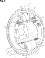
- the FIGURE 8 represents a "dual-mode" drum brake mechanism in one embodiment of the invention. This embodiment can be implemented with different types of actuators for the service brake mode.
- Linear actuator 2 (see also FIGURE 7 ) activates in parking brake or emergency mode.
- the linear actuating assembly 3 presses first ends 122, 132 of the segments 12, 13 to move them away from each other, and thus put the segments in abutment against the friction track of the drum 15 of the brake. Since the position of rest, or from the service braking position, the linear actuator 2 thus puts the brake in the parking braking position, and the return to the rest position is achieved for example by return springs interconnecting the two segments by soliciting them towards each other.
- the assembly formed by the two segments interconnected by a connecting rod 14 in the vicinity of their second ends and by the linear actuating assembly 3 in the vicinity of their first ends 122, 132 tends to be rotated with the drum. This movement is prevented by abutting one of two shoulders 329, 339 (depending on the direction of rotation) of the linear actuating assembly 3 against a corresponding surface of the housing 21.
- the embodiment which has just been described is in no way limiting.
- the elements specific to the actuator 2 of the parking brake or emergency brake can be integrated as such within any type of drum brake, including a two-mode drum brake type duo-servo or drum-in-hat type.
Description
La présente invention se rapporte à un motoréducteur, en particulier pour motoriser un actionneur de frein à disque ou à tambour de véhicule automobile, par exemple dans le cadre d'un frein à tambour de type « bi-mode ». La présente invention se rapporte aussi à un frein à tambour et à un dispositif de freinage ainsi équipés.The present invention relates to a geared motor, in particular for motorizing a disk brake actuator or drum motor vehicle, for example in the context of a drum brake type "dual mode". The present invention also relates to a drum brake and a braking device thus equipped.
Un motoréducteur se compose en général d'un moteur électrique dont l'arbre de sortie est raccordé à un ensemble d'engrenages produisant une réduction de la vitesse et une augmentation du couple, ce qui est très souvent avantageux pour réaliser une motorisation électrique. Dans la plupart des cas, un motoréducteur comprend des pignons à contacts extérieurs qui sont placés en cascade.A geared motor generally consists of an electric motor whose output shaft is connected to a gear assembly producing a reduction in speed and an increase in torque, which is very often advantageous to achieve an electric motor. In most cases, a gearmotor includes pinions with external contacts that are cascaded.
Un frein à tambour classique comprend typiquement un tambour, coaxial avec la roue, et consistant en un cylindre creux solidaire de la pièce à freiner. Lors du freinage, les garnitures des segments de freinage frottent sur la surface intérieure du tambour. Pour cela, un moyen d'actionnement écarte de l'axe une des extrémités de chacun des deux segments. Les extrémités opposées s'appuient, tangentiellement à la rotation, sur une plaque de butée solidaire d'un plateau immobilisé en rotation. Lorsque les segments sont mis en pression contre la piste du tambour, tout mouvement ou effort en rotation de la roue imprime un couple de rotation aux segments, qu'ils transmettent au plateau par cette plaque de butée. En général, les deux segments sont actionnés en leurs deux extrémités d'un même côté, typiquement par un même cylindre hydraulique à double piston, dans un mode de fonctionnement appelé « simplex ».A conventional drum brake typically comprises a drum, coaxial with the wheel, and consisting of a hollow cylinder integral with the workpiece to be braked. During braking, the linings of the brake shoes rub against the inner surface of the drum. For this, an actuating means deviates from the axis one of the ends of each of the two segments. The opposite ends are supported, tangentially to the rotation, on an abutment plate integral with a rotatably immobilized plate. When the segments are pressurized against the drum track, any movement or force in rotation of the wheel prints a torque to the segments, they transmit to the plate by this stop plate. In general, the two segments are actuated at their two ends on the same side, typically by the same hydraulic cylinder with double piston, in a mode of operation called "simplex".
Il est également connu d'actionner électriquement les segments d'un frein à tambour. Ainsi, le document
Les documents
Un but de la présente invention est de fournir un motoréducteur bien adapté à un actionneur de frein à tambour, en particulier compact, robuste, économique et avec un bon rendement énergétique.An object of the present invention is to provide a geared motor well suited to a drum brake actuator, in particular compact, robust, economical and with a good energy efficiency.
Suivant un premier aspect de l'invention, le motoréducteur comprenant un moteur électrique, un réducteur et une sortie rotative couplée au moteur électrique par l'intermédiaire du réducteur, est caractérisé en ce qu'il comprend en outre un boîtier dans lequel est fixé le moteur et en ce que le réducteur est à train épicycloïdal et comprend au moins une couronne dentée intérieurement qui est solidaire du boîtier et formée dans la matière dudit boîtier.According to a first aspect of the invention, the geared motor comprising an electric motor, a gear and a rotary output coupled to the electric motor via the gearbox, is characterized in that it further comprises a housing in which is fixed the motor and in that the gearbox is epicyclic gear and comprises at least one ring gear internally which is integral with the housing and formed in the material of said housing.
Une motorisation électrique fournit souvent des vitesses de rotation élevées, ce qui oblige à prévoir une très grande démultiplication pour obtenir un déplacement faible avec un effort suffisant. Cela est rendu possible par au moins un réducteur à train épicycloïdal à couronne fixe. De plus, lorsque l'environnement d'une telle motorisation est exposé aux poussières ou saletés, le mécanisme motoréducteur doit être protégé et relativement étanche vis-à-vis de cet environnement, en particulier dans le cas de la motorisation d'un actionneur de frein à tambour. Le mécanisme motoréducteur selon l'invention contenu dans un boîtier dans lequel est formée la couronne dentée intérieurement pour le train épicycloïdal permet de satisfaire à tout ou partie de ces contraintes. Le boîtier étant immobilisé en rotation, il fournit à la couronne le couple de réaction nécessaire au fonctionnement du train épicycloïdal. Il est en outre facile et économique à fabriquer. L'invention procure notamment un bon rendement énergétique de la transmission depuis la motorisation, ce qui permet d'obtenir un effort plus important ou une vitesse d'actionnement plus élevée ou d'utiliser une motorisation moins puissante, ou un meilleur compromis entre ces performances. Elle permet une facilité et une souplesse d'adaptation aux besoins et contraintes d'un concepteur de véhicule ou de sous-ensemble de véhicule ; par exemple pour l'adaptation à des véhicules ou des sous-ensembles de véhicule existants, ou pour l'intégration dans des véhicules ou des sous-ensembles de véhicule en cours de conception. En particulier, l'invention est compatible avec les évolutions techniques des modes de commande des organes automobiles, notamment dans le cas du frein de stationnement à commande électrique. Elle permet aussi de mettre en oeuvre plusieurs niveaux de performances de motorisation avec un même modèle d'actionneur.An electric motor often provides high speeds of rotation, which requires to provide a very large gear to obtain a low displacement with sufficient effort. This is made possible by at least one fixed-ring epicyclic gearbox. In addition, when the environment of such a motorization is exposed to dust or dirt, the gearmotor mechanism must be protected and relatively sealed vis-à-vis the environment, particularly in the case of motorization of a motor actuator. drum brake. The geared motor mechanism according to the invention contained in a housing in which is formed the ring gear internally for the planetary gear train satisfies all or part of these constraints. The housing being immobilized in rotation, it provides the ring with the reaction torque necessary for the operation of the planetary gear train. It is also easy and economical to manufacture. The invention notably provides a good energetic efficiency of the transmission from the motorization, which makes it possible to obtain a greater force or a higher speed of actuation or to use a motorization less powerful, or a better compromise between these performances. It allows ease and flexibility of adaptation to the needs and constraints of a vehicle designer or vehicle subassembly; for example for adaptation to existing vehicles or vehicle subassemblies, or for integration into vehicles or vehicle subassemblies being designed. In particular, the invention is compatible with the technical evolutions of the control modes of the automobile components, in particular in the case of the electrically controlled parking brake. It also makes it possible to implement several levels of engine performance with the same model of actuator.
Selon des perfectionnements optionnels de l'invention :
- le réducteur comprend deux trains épicycloïdaux montés mécaniquement en série de façon que la sortie d'un premier de ces trains soit solidaire en position angulaire de l'entrée d'un deuxième de ces trains, ladite au moins une couronne comprenant deux couronnes faisant partie chacune de l'un des deux trains ;
- les deux couronnes sont formées par une unique denture ayant une dimension axiale correspondant à celle des deux trains montés dans le boîtier à la suite l'un de l'autre dans le prolongement axial du moteur ;
- le boîtier comprend un collet séparant le moteur et le réducteur, et le réducteur comprend une roue planétaire menante, un porte-satellites mené, et des satellites qui sont montés en libre rotation sur des tourillons de ce porte-satellites mené et en libre translation sur ces tourillons entre le collet et ce porte-satellites mené ;
- dans le cas où il y a deux trains épicycloïdaux, le deuxième train comprend une roue planétaire menante solidaire en rotation d'un porte-satellites du premier train, un porte-satellites mené, et des satellites qui sont montés en libre rotation sur des tourillons de ce porte-satellites mené et en libre translation sur ces tourillons entre le porte-satellites mené et le porte-satellites du premier train ;
- la sortie rotative est solidaire d'un porte-satellites mené qui est maintenu axialement par un jonc d'arrêt engagé dans une rainure formée dans la matière du boîtier à une première extrémité de la couronne dentée, l'ensemble des composants mobiles du réducteur ayant une liberté de positionnement axial mutuel entre le jonc d'arrêt et un épaulement formé intérieurement sur le boîtier en une seconde extrémité de la couronne ;
- la couronne et le moteur sont montés coaxiaux.
- the gearbox comprises two epicycloidal gear trains mechanically mounted in series so that the output of a first of these trains is secured in angular position to the input of a second of these trains, said at least one ring comprising two crowns each forming part one of the two trains;
- the two rings are formed by a single toothing having an axial dimension corresponding to that of the two trains mounted in the housing following one another in the axial extension of the motor;
- the housing comprises a collar separating the motor and the gearbox, and the gearbox comprises a driving planet wheel, a planet carrier, and satellites which are mounted for free rotation on the journals of this planet carrier and freely translatable on these trunnions between the collar and this led planet carrier;
- in the case where there are two planetary gear trains, the second train comprises a driving planet wheel rotatably integral with a planet carrier of the first train, a planet carrier, and satellites which are mounted in free rotation on journals this planet carrier conducted and freely translatable on these pins between the planet carrier and the planet carrier of the first train;
- the rotary output is integral with a driven planet carrier which is held axially by a snap ring engaged in a groove formed in the housing material at a first end of the ring gear, all moving components of the gear unit having a mutual axial positioning freedom between the snap ring and a shoulder formed internally on the housing at a second end of the ring gear;
- the crown and the motor are mounted coaxial.
Ces perfectionnements facilitent grandement la réalisation d'un tel motoréducteur, ainsi que son assemblage et sa maintenance, ce qui, par conséquent, réduit les coûts engagés par de telles actions.These improvements greatly facilitate the realization of such a geared motor, as well as its assembly and maintenance, which, therefore, reduces the costs incurred by such actions.
Le motoréducteur décrit ici est adaptable à différents types de freins à tambour et de fonctions de freinage.The geared motor described here is adaptable to different types of drum brakes and braking functions.
Les freins à tambour sont typiquement utilisés dans les véhicules automobiles afin de réaliser trois types de freinage :
- le freinage de service, qui consiste à ralentir et/ou immobiliser le véhicule, typiquement par l'intermédiaire d'une pédale de freinage ;
- le freinage de stationnement, qui permet d'immobiliser le véhicule à l'arrêt, typiquement par l'intermédiaire d'un frein à main ;
- le freinage de secours, qui consiste à ralentir et/ou immobiliser le véhicule en cas de défaillance du freinage de service, et qui est typiquement assuré par le même dispositif que le freinage de stationnement.
- service braking, which consists in slowing down and / or immobilizing the vehicle, typically via a brake pedal;
- parking braking, which makes it possible to immobilize the vehicle at a standstill, typically by means of a parking brake;
- emergency braking, which consists in slowing down and / or immobilizing the vehicle in the event of failure of the service braking, and which is typically provided by the same device as the parking brake.
Dans la plupart des véhicules équipés de freins à tambour, ces trois types de freinage sont réalisés par le même frein à tambour. Spécifiquement et typiquement, la fonction de freinage de stationnement est assurée par un câble reliant une commande de frein à main dans l'habitacle à un levier pivotant dans le tambour autour d'une extrémité mobile d'un premier segment de freinage et écartant un second segment de freinage via une biellette de réaction.In most vehicles equipped with drum brakes, these three types of braking are performed by the same drum brake. Specifically and typically, the parking brake function is provided by a cable connecting a handbrake control in the passenger compartment to a lever pivoting in the drum about a movable end of a first braking segment and bypassing a second braking segment via a reaction rod.
Un frein à tambour ainsi actionné fournit en mode simplex décrit plus haut un couple de freinage qui peut être insuffisant pour assurer un freinage de stationnement et surtout un freinage de secours.A drum brake thus actuated provides in simplex mode described above a braking torque which may be insufficient to provide parking braking and especially emergency braking.
On a ainsi développé les freins à tambour fonctionnant en mode « duo-servo », dans lesquels une biellette flottante transmet et amplifie l'effort d'un segment à l'autre segment. En particulier, un actionneur écarte une extrémité d'un premier segment lequel s'appuie sur le tambour pendant que son autre extrémité prend appui, par l'intermédiaire de la biellette flottante, sur le deuxième segment par son extrémité en vis-à-vis, flottante elle aussi. Ainsi, l'extrémité opposée du deuxième segment est la seule à prendre appui sur une plaque de butée. Ce type de frein amplifie fortement l'effort d'actionnement mais il est plus délicat à ajuster et provoque une usure irrégulière des garnitures.Thus, drum brakes operating in "duo-servo" mode have been developed, in which a floating link transmits and amplifies the effort from one segment to the other segment. In particular, an actuator separates one end of a first segment which rests on the drum while its other end is supported, via the floating link, on the second segment by its end facing it. floating her too. Thus, the opposite end of the second segment is the only one to bear on a stop plate. This type of brake greatly amplifies the actuating force but is more difficult to adjust and causes irregular wear of the linings.
Les freins à tambour de type duo-servo sont souvent utilisés exclusivement comme frein de stationnement et de secours, par exemple en utilisant comme tambour la cloche centrale du disque d'un frein à disque de service, combinaison appelée « drum-in-hat » et décrite dans le document
Un autre type de frein combine le mode simplex pour le freinage de service et le mode duo-servo pour le freinage de stationnement et de secours. Dans cet esprit, le document
Dans son potentiel d'adaptabilité à ces différents types de frein et/ou de fonctions de freinage, un second aspect de l'invention présente d'autres caractéristiques avantageuses selon lesquelles l'invention peut consister en un frein à tambour dans lequel les deux segments sont montés sur un plateau de façon à pouvoir s'écarter l'un de l'autre pour venir en appui sur la piste de frottement portée par l'intérieur d'un tambour mobile en rotation par rapport audit plateau, l'actionneur réalisé sous la forme d'un actionneur linéaire étant agencé pour écarter les deux segments par leurs deux premières extrémités en vis-à-vis l'une de l'autre.In its potential for adaptability to these different types of brakes and / or braking functions, a second aspect of the invention has other advantageous features according to which the invention may consist of a drum brake in which the two segments are mounted on a plate so as to be able to deviate from one another in order to bear on the friction track carried by the inside of a rotating drum relative to said plate, the actuator produced under the shape of a linear actuator being arranged to separate the two segments by their first two ends vis-à-vis one another.
Dans un tel frein, selon une particularité, les deux segments sont articulés à une biellette mobile par rapport au plateau et qui les relie entre eux au voisinage de leurs deuxièmes extrémités, opposées aux premières extrémités, ladite biellette étant apte à transmettre de l'un des segments à l'autre desdits segments un effort qui pousse cet autre segment en appui contre un élément d'ancrage fixe par rapport au plateau.In such a brake, according to a feature, the two segments are articulated to a rod movable relative to the plate and which connects them in the vicinity of their second ends, opposite to the first ends, said link being able to transmit one of segments to the other of said segments a force which pushes the other segment in abutment against an anchor element fixed relative to the plate.
Selon une autre particularité, le frein comprend en outre un deuxième actionneur assurant une deuxième fonction de freinage, notamment de service, ce deuxième actionneur étant agencé pour écarter l'une de l'autre les deuxièmes extrémités des deux segments tandis que les premières extrémités viennent en butée par rapport au plateau.According to another feature, the brake further comprises a second actuator providing a second braking function, in particular of service, this second actuator being arranged to separate from one another the second ends of the two segments while the first ends abut in relation to the plate.
Enfin, selon une autre caractéristique avantageuse, l'invention consiste en un dispositif de freinage, dit "Drum In Hat", pour véhicule ou sous-ensemble de véhicule, notamment routier, comprenant un disque de frein interagissant avec des plaquettes de frein pour réaliser une deuxième fonction de freinage, notamment de frein de service, ce dispositif comprenant un frein agencé pour assurer une première fonction de freinage, notamment de frein de stationnement et/ou de secours, dans lequel le tambour est solidaire de, et coaxial avec, ledit disque de frein.Finally, according to another advantageous characteristic, the invention consists of a braking device, called "Drum In Hat", for a vehicle or subassembly of a vehicle, in particular a road vehicle, comprising a brake disc interacting with brake pads to realize a second braking function, in particular a service brake, this device comprising a brake arranged to provide a first braking function, in particular a parking brake and / or emergency brake, in which the drum is integral with, and coaxial with, said brake disc.
Le motoréducteur décrit ici est aussi adaptable à d'autres types de freins, comme par exemple un frein à disque.The geared motor described here is also adaptable to other types of brakes, such as a disc brake.
Dans son potentiel d'adaptabilité à ces différents types de frein et/ou de fonctions de freinage, un autre aspect de l'invention porte ainsi sur un frein à disque comprenant un étrier monté à cheval sur la périphérie d'un disque de freinage solidaire d'une roue mobile en rotation autour demi-train roulant par exemple un porte fusée. Cet étrier est monté solidaire en rotation par rapport audit porte fusée et enserre ledit disque sur ses deux faces entre au moins deux garnitures de frottement sous l'effet d'un effort de serrage appliqué sur au moins l'une desdites garnitures par un piston de freinage déplacé en translation parallèlement à l'axe de roue. Selon l'invention, ce frein à disque comprend un motoréducteur tel qu'exposé ici, qui est monté sur ledit étrier de façon à actionner ledit piston. Ce motoréducteur est par exemple fixé sur l'étrier et entraîne un mécanisme vis-écrou formant un actionneur linéaire coaxial au piston de freinage et dont la rotation déplace le piston pour serrer les garnitures contre le disque.In its potential for adaptability to these different types of brakes and / or braking functions, another aspect of the invention thus relates to a disc brake comprising a stirrup mounted astride the periphery of a solidarity brake disc. a moving wheel rotating around a half-running train for example a rocket door. This stirrup is mounted integral in rotation with respect to said rocket door and encloses said disk on its two faces between at least two friction linings under the effect of a clamping force applied to at least one of said linings by a piston of braking moved in translation parallel to the wheel axis. According to the invention, this disc brake comprises a geared motor as described herein, which is mounted on said stirrup so as to actuate said piston. This geared motor is for example fixed on the caliper and drives a screw-nut mechanism forming a linear actuator coaxial with the brake piston and whose rotation moves the piston to tighten the liners against the disk.
D'autres particularités et avantages de l'invention ressortiront de la description détaillée d'un mode de réalisation nullement limitatif et des dessins annexés où :
- la
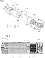
FIGURE 1 est une vue éclatée du motoréducteur dans un exemple de réalisation de l'invention ; - la
FIGURE 2 est une vue en coupe du motoréducteur de laFIGURE 1 ; - la
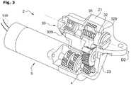
FIGURE 3 est une vue en perspective et écorché partiel d'un actionneur de frein de stationnement ou de secours comprenant le motoréducteur de laFIGURE 1 , dans un exemple de réalisation de l'invention ; - la
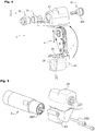
FIGURE 4 est une vue éclatée de l'actionneur de laFIGURE 3 sans le motoréducteur ; - la
FIGURE 5 est une vue éclatée de l'actionneur de laFIGURE 3 ; - la
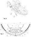
FIGURE 6 est une vue éclatée de l'actionneur de laFIGURE 3 et d'un plateau de frein à tambour, dans un exemple de réalisation de l'invention ; - la
FIGURE 7 représente schématiquement, en vue de face, le fonctionnement d'un mécanisme de frein à tambour de type « bi-mode » lors du serrage, véhicule immobile, du frein de stationnement ; - la
FIGURE 8 est une vue en perspective d'un mécanisme de frein à tambour de type « bi-mode » comprenant l'actionneur de laFIGURE 3 , dans un exemple de réalisation de l'invention.
- the
FIGURE 1 is an exploded view of the geared motor in an exemplary embodiment of the invention; - the
FIGURE 2 is a sectional view of the gearmotor of theFIGURE 1 ; - the
FIGURE 3 is a perspective view and partial skin of an actuator parking brake or emergency brake comprising the gearmotor of theFIGURE 1 in an exemplary embodiment of the invention; - the
FIGURE 4 is an exploded view of the actuator of theFIGURE 3 without the geared motor; - the
FIGURE 5 is an exploded view of the actuator of theFIGURE 3 ; - the
FIGURE 6 is an exploded view of the actuator of theFIGURE 3 and a drum brake plate, in one embodiment of the invention; - the
FIGURE 7 shows schematically, in front view, the operation of a "dual-mode" type drum brake mechanism when the parking brake is stationary; - the
FIGURE 8 is a perspective view of a "dual-mode" type drum brake mechanism comprising the actuator of theFIGURE 3 in an exemplary embodiment of the invention.
Dans le mode de réalisation de la
Avantageusement, le boîtier 51 est prévu avec un logement intérieur cylindrique d'un diamètre suffisamment grand pour pouvoir accueillir des moteurs de plusieurs diamètres différents, par exemple jusqu'à 34 mm, de façon à pouvoir fabriquer des motoréducteurs 5 de plusieurs valeurs de puissance différentes avec un même modèle de boîtier.Advantageously, the
Pour bien positionner et maintenir le moteur dans le boîtier, quel que soit le diamètre du moteur, celui-ci est emboîté dans une cale tubulaire 53 dont l'épaisseur représente la différence entre le rayon du moteur 52 et celui du logement intérieur du boîtier 51. Pour une gamme donnée de moteurs de diamètres différents, il suffit ainsi de fabriquer une gamme de cales aux diamètres intérieurs correspondants, ce qui est plus simple et économique que de fabriquer des boîtiers de dimensions différentes.To properly position and maintain the motor in the housing, regardless of the diameter of the motor, it is fitted into a
Alternativement, la cale tubulaire 53 est solidaire du couvercle arrière 54, ou même formée sur celui-ci. En variante, ce couvercle présente une forme plus allongée que celle représentée, de façon à recouvrir toute la longueur du moteur 52. Dans ce cas, la gamme de moteurs différents correspond avantageusement à une gamme de couvercles différents, pour un même boîtier 51.Alternatively, the
La cale tubulaire 53, ou le couvercle 54 s'il la remplace, est en outre réalisée en une matière qui forme un écran contre les perturbations électromagnétiques et/ou qui réalise un diffuseur thermique pour la chaleur produite par le moteur.The
Du côté de l'arbre du moteur, le boîtier 51 comporte une ouverture de sortie 510 cylindrique renfermant un réducteur à engrenages, qui est entraîné en entrée par le moteur 52 et entraîne en sortie l'arbre de sortie 557 du motoréducteur 5. Comme indiqué en
La carter du moteur 52 comporte au moins une dent 528 excentrée qui s'emboîte axialement dans un évidement 543 du couvercle 54 pour immobiliser le moteur 52 à l'encontre de toute rotation dans le boîtier 51.The housing of the
L'arbre du moteur traverse le collet 57 et un flasque d'étanchéité 561 adossé au collet. Il porte un pignon 551 qui lui est solidaire et forme un planétaire menant d'un premier train épicycloïdal 55A dans lequel des premiers satellites 552 engrènent avec ce planétaire et avec une première couronne 559 dentée intérieurement qui les entoure. Les premiers satellites 552 sont montés en libre rotation sur des tourillons excentrés d'un premier porte-satellites 553, et en libre translation axiale sur les tourillons entre le collet 57 et le premier porte-satellites 553. Ce dernier constitue la sortie du premier train épicycloïdal 55A et porte un pignon planétaire 554 dont il est solidaire en rotation, formant l'entrée d'un deuxième train épicycloïdal 55B comprenant des deuxièmes satellites 555 engrenant avec le planétaire 554 et avec une deuxième couronne dentée intérieurement qui les entoure. Les deuxièmes satellites 555 sont montés en libre rotation sur des tourillons d'un deuxième porte-satellites 556, et en libre translation axiale sur ces tourillons entre le premier porte-satellites 553 et le deuxième porte-satellites 556. Ce dernier constitue la sortie du deuxième train épicycloïdal 55B et porte l'arbre de sortie 557 du motoréducteur 5, dont il est solidaire. Le deuxième porte-satellites 556 est maintenu en position axiale dans l'ouverture 510 avec un jeu de fonctionnement approprié par un jonc d'arrêt 563, par exemple un Circlips (marque déposée), engagé dans une rainure formée intérieurement dans la matière du boîtier 51.The motor shaft passes through the
Dans ce mode de réalisation, les deux trains 55A, 55B sont montés dans le boîtier 51 à la suite d'un de l'autre, dans le prolongement axial du moteur 52. L'ensemble des composants mobiles du réducteur 55 a une liberté de positionnement axial mutuel pour un jeu de fonctionnement convenable entre le jonc d'arrêt 563 et un épaulement 58 formé intérieurement sur le boîtier 51, en particulier sur le collet 57.In this embodiment, the two
La première et la deuxième couronnes sont coaxiales avec le moteur 52. De préférence, les deux trains sont à denture hélicoïdale corrigée.The first and second rings are coaxial with the
Les deux couronnes dentées intérieurement sont formées dans la matière du boîtier 51, sur la face intérieure de l'ouverture 510. De préférence, le boîtier est réalisé dans une matière moulable et les deux couronnes sont venues de moulage avec le boîtier. Il est par ailleurs préféré que les deux couronnes soient de même diamètre et de même taille de denture (à part éventuellement la longueur axiale de la denture, le deuxième train subissant des efforts qui sont multipliés par le rapport de réduction du premier train). Très préférentiellement, comme représenté sur la
Le boîtier 51 et le couvercle 54 du motoréducteur sont réalisés par exemple en métal moulé, ou en polymères chargé de fibres de verre. Les satellites 552, 555 sont réalisés par exemple en polyoxyméthylène. Les porte-satellites 553, 556 et leurs arbres de sortie 554, 557 avec la forme d'entraînement de sortie sont réalisés par exemple en acier, usiné ou par frittage laser.The
Dans un exemple de réalisation, les dentures et dimensions du motoréducteur 5 ont été déterminées pour produire un rapport de réduction d'une valeur de 23,04:1 pour un rendement compris entre 0,85 et 0,92.In an exemplary embodiment, the teeth and dimensions of the geared
Dans le mode de réalisation des
L'ensemble d'actionnement linéaire 3 est monté dans un boîtier 21, aussi appelé boîtier principal. Le boîtier 21 sert à ancrer l'actionneur linéaire 2 sur un plateau 10 d'un frein à tambour, comme illustré en
Dans ce mode de réalisation, la roue d'entrée 41 de l'engrenage de transmission 4 est couplée en rotation avec le motoréducteur 5, ici par emboîtement d'un alésage axial portant une forme d'entraînement (non représentée) avec une forme d'entraînement complémentaire (non représentée) portée par l'arbre de sortie 557 du motoréducteur 5. La géométrie de ces deux formes d'entraînement complémentaires est avantageusement choisie d'un type qui permet entre elles un certain jeu angulaire avec peu ou pas de dommages et de pertes de rendement de la puissance transmise. Cette géométrie est ici de type multi-lobulaire, par exemple à six branches ou hexalobulaire tel que défini par la norme ISO 10664, ou dans une version à cinq branches, ou l'une ou l'autre des versions proposées sous le nom de « Torx » (marque déposée) par la société Textron.In this embodiment, the
Comme indiqué en
Comme illustré en
Comme on le voit en
La
L'actionneur linéaire 2 (voir aussi
Le mode de réalisation qui vient d'être décrit n'est nullement limitatif. En particulier, les éléments propres à l'actionneur 2 du frein de stationnement ou de secours peuvent être intégrés tels quels au sein de tout type de frein à tambour, notamment d'un frein à tambour bi-mode de type duo-servo ou encore de type drum-in-hat.The embodiment which has just been described is in no way limiting. In particular, the elements specific to the
- 11
- frein à tambourdrum brake
- 1010
- plateau supportsupport tray
- 100100
- ouverture de plateautray opening
- 1111
- deuxième actionneur - frein de servicesecond actuator - service brake
- 12, 1312, 13
- segments de freinagebraking segments
- 122, 132122, 132
- premières extrémités des segmentsfirst ends of the segments
- 1414
- élément intercalaire - biellette de rattrapage de jeuinterleaving element - play catch-up link
- 1515
- tambour de rouewheel drum
- 22
- actionneur linéaire - frein de stationnement ou de secourslinear actuator - parking or emergency brake
- 2121
- boîtier principalmain housing
- 2323
- boîtier secondairesecondary housing
- 233233
- vis de fixation du boîtier secondaire sur le boîtier du motoréducteurfastening screw for the secondary housing on the geared motor housing
- 2424
- logement de l'engrenage de transmission dans le boîtier secondairehousing of the transmission gear in the secondary housing
- 2525
- logement du motoréducteur dans le boîtier secondaireGeared motor housing in the secondary housing
- 33
- ensemble d'actionnement linéairelinear actuation assembly
- 3131
- écrou de système vis-écrouscrew-nut system nut
- 3232
- vis de système vis-écrouscrew of system screw-nut
- 329329
- épaulement d'appui de la vis - transmission du couple de freinagesupport shoulder of the screw - braking torque transmission
- 3333
- piston élastique linéaire - « spring package »linear elastic piston - "spring package"
- 339339
- épaulement d'appui du piston élastique - transmission du couple de freinagesupport shoulder of the elastic piston - braking torque transmission
- 44
- engrenage de transmissiontransmission gear
- 4141
- roue dentée - roue d'entréegear wheel - input wheel
- 55
- motoréducteurgearmotor
- 5151
- boîtier de motoréducteurgeared motor housing
- 510510
- ouverture de sortie cylindrique - logement de train épicycloïdalcylindrical exit opening - epicyclic gear housing
- 5252
- moteur électriqueelectric motor
- 528528
- denttooth
- 529529
- alimentation électrique du moteurmotor power supply
- 5353
- cale tubulaire - formant écran électromagnétique et diffuseur thermiquetubular wedge - forming electromagnetic shield and thermal diffuser
- 5454
- couvercle arrière de moteurrear engine cover
- 543543
- évidementrecess
- 5555
- mécanisme de réduction épicycloïdalepicyclic reduction mechanism
- 55A55A
- premier train épicycloïdalfirst epicyclic train
- 551551
- pignon planétaire de 1° train épicycloïdal - pignon d'entréeplanetary gear of 1st epicyclic gear - input pinion
- 552552
- pignons satellites de 1° train épicycloïdalplanet gears of 1 ° epicyclic gear
- 553553
- porte satellites de 1° train épicycloïdalsatellite carriers of 1 ° epicyclic gear
- 55B55B
- deuxième train épicycloïdalsecond epicyclic train
- 554554
- pignon planétaire de 2° train épicycloïdalplanetary gear of 2 ° epicyclic gear
- 555555
- pignons satellites de 2° train épicycloïdalplanetary gears of 2 ° epicyclic gear
- 556556
- porte satellites de 2° train épicycloïdalsatellite carriers of 2 ° epicyclic gear
- 557557
- arbre de sortieoutput shaft
- 559559
- couronne des trains épicycloïdauxcrown of planetary gear trains
- 561561
- flasque d'étanchéitésealing flange
- 563563
- jonc d'arrêtsnap ring
- 5757
- collet de séparation du moteur et du mécanisme de réductionengine separation collar and reduction mechanism
- 5858
- épaulement côté réducteurshoulder on the reducer side
Claims (12)
- Geared motor (5) comprising an electric motor (52), a reduction gear and a rotary output (557) coupled to said electric motor via said reduction gear, further comprising a housing (51) in which said motor is fixed, said reduction gear having a planetary gear set, characterized in that the reduction gear comprises at least one internal ring gear (559) that is integral with the housing (51) and formed in the material of said housing.
- Geared motor according to the preceding claim, characterized in that the reduction gear (55) comprises two planetary gear sets (55A, 55B) mounted mechanically in series such that the output (553) of a first (55A) of said gear sets is firmly fixed in an angular position to the input (554) of a second (55B) of said gear sets, the at least one ring gear (559) comprising two ring gears each forming part of one of said two gear sets.
- Geared motor according to the preceding claim, characterized in that the two ring gears are formed by a single set of teeth with an axial dimension that corresponds to the axial dimension of the two gear sets (55A, 55B) mounted in the housing (51) one after the other in the axial extension of the motor (52).
- Geared motor according to any one of the preceding claims, characterized in that the housing (51) comprises a collar (57) separating the motor (52) and the reduction gear (55), and in that said reduction gear comprises a driving planet gear (551), a driven planet carrier (553), and pinion gears (552) that mesh with the driving planet gear and the ring gear, and are mounted free to rotate on pins of said driven planet carrier and free to translate axially on said pins between said collar and said driven planet carrier.
- Geared motor according to claim 2 or 3, characterized in that the second gear set (55B) comprises a driving planet gear (554) firmly fixed in rotation to a planet carrier (553) of the first gear set (55A), a driven planet carrier (556), and pinion gears (555) that mesh with the driving planet gear of the second gear set and with the ring gear of the second gear set, and are mounted free to rotate on pins of said driven planet carrier and free to translate axially on said pins between said driven planet carrier (556) and said planet carrier (553) of the first gear set.
- Geared motor according to any one of claims 1 to 3, characterized in that the rotary output (557) is firmly fixed to a planet carrier (556) that is retained axially by a snap ring (563) engaged in a groove formed in the material of the housing (51) at a first end of the ring gear (559), all of the mobile elements of the reduction gear (55) being freely positioned axially in relation to each other between said snap ring and a shoulder (58) formed on the inside of said housing at a second end of said ring gear.
- Geared motor according to any one of the preceding claims, characterized in that the ring gear (559) and the motor (52) are coaxial.
- Drum brake (1) comprising two shoes (12, 13) mounted on a backing plate (10) so as to be able to move apart from each other to press on a braking surface borne by the inside of a drum mobile in rotation relative to said backing plate, characterized in that it comprises a linear actuator (2) driven by a geared motor according to any one of the preceding claims, which linear actuator is arranged in order to move apart two first ends (122, 132) of said shoes, which are facing each other.
- Brake according to the preceding claim, characterized in that the two shoes (12, 13) are hinged on a rod (14) that is mobile relative to the backing plate and connects them to each other in the vicinity of the second ends thereof, opposite the first ends, said rod being capable of transmitting from one shoe (12) to the other (13) a force that pushes said other shoe (13) against an anchor (21) that is fixed relative to the backing plate (10).
- Brake according to claim 8 or 9, characterized in that it also comprises a second actuator providing a second braking function, in particular service braking (11), said second actuator being arranged in order to move the second ends of the two shoes (12, 13) apart from each other while the first ends (122, 132) abut against the backing plate (10).
- Braking device for a vehicle or vehicle sub-assembly, in particular a road vehicle, comprising a brake disc interacting with brake pads to provide a second braking function, in particular service braking, characterized in that it comprises a drum brake according to claim 8 or 9, arranged in order to provide a first braking function, in particular parking and/or emergency braking, and in that the drum thereof is firmly fixed to and coaxial with said brake disc.
- Disc brake comprising a caliper mounted straddling the periphery of a brake disc that is firmly fixed to a wheel mobile in rotation about a hub carrier, said caliper being firmly fixed in rotation to said hub carrier and clasping the two faces of said disc between at least two friction linings under the effect of a clamping force applied to at least one of said linings by a brake piston displaced in translation in parallel to the wheel shaft, characterized in that it comprises a geared motor according to any one of claims 1 to 7 mounted on said caliper and arranged in order to actuate said piston.
Priority Applications (1)
| Application Number | Priority Date | Filing Date | Title |
|---|---|---|---|
| PL14827445T PL3089901T3 (en) | 2013-12-30 | 2014-12-23 | Motor-reducer with planetary gearset, drum and disc brake and braking device provided with same |
Applications Claiming Priority (2)
| Application Number | Priority Date | Filing Date | Title |
|---|---|---|---|
| FR1363708A FR3016015B1 (en) | 2013-12-30 | 2013-12-30 | EPICYCLOIDAL TRAIN MOTOREDUCER AND DRUM BRAKE AND BRAKING DEVICE SO EQUIPPED |
| PCT/EP2014/079203 WO2015101562A2 (en) | 2013-12-30 | 2014-12-23 | Motor-reducer with planetary gearset and drum brake and braking device provided with same |
Publications (2)
| Publication Number | Publication Date |
|---|---|
| EP3089901A2 EP3089901A2 (en) | 2016-11-09 |
| EP3089901B1 true EP3089901B1 (en) | 2017-10-18 |
Family
ID=50483078
Family Applications (1)
| Application Number | Title | Priority Date | Filing Date |
|---|---|---|---|
| EP14827445.9A Active EP3089901B1 (en) | 2013-12-30 | 2014-12-23 | Motor-reducer with planetary gearset, drum and disc brake and braking device provided with same |
Country Status (8)
| Country | Link |
|---|---|
| EP (1) | EP3089901B1 (en) |
| JP (1) | JP6602306B2 (en) |
| CN (1) | CN106103221B (en) |
| ES (1) | ES2655915T3 (en) |
| FR (1) | FR3016015B1 (en) |
| PL (1) | PL3089901T3 (en) |
| PT (1) | PT3089901T (en) |
| WO (1) | WO2015101562A2 (en) |
Families Citing this family (16)
| Publication number | Priority date | Publication date | Assignee | Title |
|---|---|---|---|---|
| KR20170023319A (en) * | 2015-08-20 | 2017-03-03 | 현대모비스 주식회사 | Brake for vehicle |
| JP2017150574A (en) * | 2016-02-25 | 2017-08-31 | 日本電産コパル株式会社 | Speed reducer, and geared motor with speed reducer, electronic equipment and robot |
| JP2020102939A (en) * | 2018-12-21 | 2020-07-02 | 日本電産株式会社 | Actuator |
| FR3091323B1 (en) * | 2018-12-27 | 2020-12-11 | Foundation Brakes France | ACTUATOR FOR ELECTROMECHANICAL DRUM BRAKE WITH INCREASED ROBUSTNESS |
| FR3091244B1 (en) | 2018-12-28 | 2021-01-01 | Foundation Brakes France | DRUM BRAKE GEAR MOTOR OFFERING HIGH COMPLIANCE |
| FR3091322A1 (en) | 2018-12-28 | 2020-07-03 | Foundation Brakes France | METHOD OF DESIGNING A MOTOR-REDUCER ADAPTED TO A PARTICULAR SIZE |
| FR3091245B1 (en) | 2018-12-28 | 2021-07-09 | Foundation Brakes France | DRUM BRAKE GEAR MOTOR |
| FR3096013B1 (en) | 2019-05-13 | 2021-09-17 | Foundation Brakes France | MOTOR VEHICLE BRAKE KIT INCLUDING BRAKE BRACKET, GEAR MOTOR AND GEAR MOTOR HOUSING ASSEMBLED WITH BRAKE BRACKET |
| FR3096634B1 (en) | 2019-06-03 | 2021-09-24 | Foundation Brakes France | Drum brake actuator gear motor, including a reduction rate of 30 A 210 |
| FR3097021B1 (en) | 2019-06-07 | 2021-09-10 | Foudation Brakes France | REDUCER AND GEAR MOTOR FOR INTEGRATED BRAKE |
| FR3111489B1 (en) | 2020-06-15 | 2022-11-04 | Foundation Brakes France | GEAR MOTOR AND MOTOR VEHICLE PARKING BRAKE IMPLEMENTING SUCH A GEAR MOTOR |
| FR3118342B1 (en) | 2020-12-21 | 2024-02-09 | Foudation Brakes France | ELECTRIC MOTOR WITH SIMPLIFIED CONTROL AND MOTOR VEHICLE PARKING BRAKE USING SUCH A MOTOR |
| CN113280063A (en) * | 2021-06-15 | 2021-08-20 | 格陆博科技有限公司 | Coaxial direct-drive electronic parking actuator |
| CN113815580A (en) * | 2021-10-22 | 2021-12-21 | 梁清明 | Motor braking speed reduction equipment for electric scooter based on new energy |
| FR3129341B1 (en) | 2021-11-24 | 2024-02-16 | Hitachi Astemo France | Method for electrically controlling a parking brake |
| FR3130000B1 (en) | 2021-12-03 | 2024-02-02 | Hitachi Astemo France | Electric actuator for a motor vehicle brake comprising a screw-nut device |
Citations (9)
| Publication number | Priority date | Publication date | Assignee | Title |
|---|---|---|---|---|
| US5322145A (en) | 1989-08-29 | 1994-06-21 | Kelsey-Hayes Company | Drum brake operating mechanism |
| DE19736734A1 (en) | 1996-08-24 | 1998-02-26 | Gerd Hoermansdoerfer | Rotational to traverse motion converter for vehicle brake |
| DE19846420A1 (en) | 1998-10-08 | 2000-04-13 | Volkswagen Ag | Drum brake for a motor vehicle |
| DE19851670A1 (en) | 1998-11-10 | 2000-05-11 | Bosch Gmbh Robert | Electromechanical wheel brake device |
| DE10393948T5 (en) | 2002-12-20 | 2005-12-15 | Aktiebolaget Skf | Electromechanical screw actuator arrangement |
| US20060000679A1 (en) | 2004-06-30 | 2006-01-05 | Dura Global Technologies, Inc. | Electronic parking brake actuating assembly |
| DE112006002895T5 (en) | 2005-10-31 | 2008-09-18 | Kelsey-Hayes Company, Livonia | Electric actuator unit for a vehicle brake assembly |
| DE102005021767B4 (en) | 2005-03-11 | 2008-10-16 | Lucas Automotive Gmbh | Electromotive actuator for a parking brake |
| DE102010032053A1 (en) | 2010-07-23 | 2012-01-26 | Lucas Automotive Gmbh | Subassembly for an electromechanical brake actuator |
Family Cites Families (11)
| Publication number | Priority date | Publication date | Assignee | Title |
|---|---|---|---|---|
| EP0416760B1 (en) | 1989-08-29 | 1994-06-01 | Kelsey-Hayes Company | Brake assembly |
| FR2697599B1 (en) | 1992-10-30 | 1994-12-30 | Bendix Europ Services Tech | Drum brake with mechanical actuation. |
| JP2001173733A (en) * | 1999-12-17 | 2001-06-26 | Namiki Precision Jewel Co Ltd | Planetary gear reduction mechanism for small motor |
| BR0307758B1 (en) * | 2002-12-20 | 2014-08-19 | Continental Teves Ag & Co Ohg | ELECTROMECANICALLY LOCKABLE BRAKE |
| DE102004049434A1 (en) * | 2004-01-21 | 2005-10-06 | Continental Teves Ag & Co. Ohg | Electromechanically actuated parking brake |
| DE102005048339A1 (en) * | 2005-10-10 | 2007-04-12 | Robert Bosch Gmbh | Parking brake for motor vehicle, has actuation installation having tie rod in form of elastic unit with spring blade and connecting element placed positioned with clearance in through bore, and actuator directly installed in brake unit |
| DE602008006750D1 (en) | 2007-10-04 | 2011-06-16 | Toyota Motor Co Ltd | PARK BRAKE SYSTEM |
| KR20100043694A (en) * | 2008-10-21 | 2010-04-29 | 주식회사 만도 | Electronic mechanical drum brake |
| JP5488909B2 (en) * | 2010-06-22 | 2014-05-14 | 日立オートモティブシステムズ株式会社 | Disc brake |
| KR20130037875A (en) * | 2011-10-07 | 2013-04-17 | 주식회사 만도 | Electronic parking brake |
| KR20130038432A (en) * | 2011-10-10 | 2013-04-18 | 주식회사 만도 | Electronic disc brake |
-
2013
- 2013-12-30 FR FR1363708A patent/FR3016015B1/en not_active Expired - Fee Related
-
2014
- 2014-12-23 PL PL14827445T patent/PL3089901T3/en unknown
- 2014-12-23 PT PT148274459T patent/PT3089901T/en unknown
- 2014-12-23 ES ES14827445.9T patent/ES2655915T3/en active Active
- 2014-12-23 JP JP2016544580A patent/JP6602306B2/en active Active
- 2014-12-23 WO PCT/EP2014/079203 patent/WO2015101562A2/en active Application Filing
- 2014-12-23 CN CN201480075047.2A patent/CN106103221B/en active Active
- 2014-12-23 EP EP14827445.9A patent/EP3089901B1/en active Active
Patent Citations (9)
| Publication number | Priority date | Publication date | Assignee | Title |
|---|---|---|---|---|
| US5322145A (en) | 1989-08-29 | 1994-06-21 | Kelsey-Hayes Company | Drum brake operating mechanism |
| DE19736734A1 (en) | 1996-08-24 | 1998-02-26 | Gerd Hoermansdoerfer | Rotational to traverse motion converter for vehicle brake |
| DE19846420A1 (en) | 1998-10-08 | 2000-04-13 | Volkswagen Ag | Drum brake for a motor vehicle |
| DE19851670A1 (en) | 1998-11-10 | 2000-05-11 | Bosch Gmbh Robert | Electromechanical wheel brake device |
| DE10393948T5 (en) | 2002-12-20 | 2005-12-15 | Aktiebolaget Skf | Electromechanical screw actuator arrangement |
| US20060000679A1 (en) | 2004-06-30 | 2006-01-05 | Dura Global Technologies, Inc. | Electronic parking brake actuating assembly |
| DE102005021767B4 (en) | 2005-03-11 | 2008-10-16 | Lucas Automotive Gmbh | Electromotive actuator for a parking brake |
| DE112006002895T5 (en) | 2005-10-31 | 2008-09-18 | Kelsey-Hayes Company, Livonia | Electric actuator unit for a vehicle brake assembly |
| DE102010032053A1 (en) | 2010-07-23 | 2012-01-26 | Lucas Automotive Gmbh | Subassembly for an electromechanical brake actuator |
Also Published As
| Publication number | Publication date |
|---|---|
| WO2015101562A3 (en) | 2015-11-19 |
| EP3089901A2 (en) | 2016-11-09 |
| CN106103221B (en) | 2018-12-18 |
| WO2015101562A2 (en) | 2015-07-09 |
| JP2017503980A (en) | 2017-02-02 |
| PL3089901T3 (en) | 2018-04-30 |
| CN106103221A (en) | 2016-11-09 |
| JP6602306B2 (en) | 2019-11-06 |
| PT3089901T (en) | 2018-01-18 |
| FR3016015B1 (en) | 2017-03-31 |
| FR3016015A1 (en) | 2015-07-03 |
| ES2655915T3 (en) | 2018-02-22 |
Similar Documents
| Publication | Publication Date | Title |
|---|---|---|
| EP3089901B1 (en) | Motor-reducer with planetary gearset, drum and disc brake and braking device provided with same | |
| EP3089898B1 (en) | Drum brake device including a parking brake operating in duo servo mode, associated vehicle and assembly methods | |
| EP3089899B1 (en) | Actuator driven by a gear having an axial guide rail, and drum brake and braking device provided with same | |
| EP3676144B1 (en) | Electromechanical brake caliper with two actuators compensating for uneven pad wear | |
| EP3090190B1 (en) | Actuator with non-reversible screw-and-nut system, drum brake and braking device provided with same | |
| EP3089896B1 (en) | Actuator with geared transmission sub-assembly, and drum brake and braking device provided with same | |
| EP3230138B1 (en) | Electric actuator for a parking brake lever arranged in a drum brake unit | |
| EP3175146B1 (en) | Torque reducer | |
| EP3175136B1 (en) | Vehicle brake actuator | |
| EP3089900B1 (en) | Motor-reducer with electric motor for drum brake actuator | |
| FR3016013A1 (en) | DRUM BRAKE ACTUATOR WITH MOTORIZATION BY EMBOITEMENT WITH ANGULAR GRIP | |
| FR3031151A1 (en) | DRUM BRAKE ADJUSTING DEVICE, CONTROL METHOD, AND METHOD FOR INDUSTRIALIZING SUCH BRAKE | |
| WO2020244936A1 (en) | Gear motor for drum brake actuator, comprising a step-down rate of 30 to 210 | |
| WO2020136325A1 (en) | Reduction motor for drum brake | |
| WO2022106777A1 (en) | Geared motor for a vehicle brake actuator with increased service life | |
| FR3097021A1 (en) | REDUCER AND GEAR MOTOR FOR BRAKE WITH INTEGRATED CLUTCH |
Legal Events
| Date | Code | Title | Description |
|---|---|---|---|
| PUAI | Public reference made under article 153(3) epc to a published international application that has entered the european phase |
Free format text: ORIGINAL CODE: 0009012 |
|
| 17P | Request for examination filed |
Effective date: 20160727 |
|
| AK | Designated contracting states |
Kind code of ref document: A2 Designated state(s): AL AT BE BG CH CY CZ DE DK EE ES FI FR GB GR HR HU IE IS IT LI LT LU LV MC MK MT NL NO PL PT RO RS SE SI SK SM TR |
|
| AX | Request for extension of the european patent |
Extension state: BA ME |
|
| RIN1 | Information on inventor provided before grant (corrected) |
Inventor name: MOLINARO, ALBERTO Inventor name: LUU, GERARD Inventor name: DUPAS, CHRISTOPHE Inventor name: GUIGNON, CEDRIC Inventor name: PASQUET, THIERRY |
|
| DAX | Request for extension of the european patent (deleted) | ||
| GRAP | Despatch of communication of intention to grant a patent |
Free format text: ORIGINAL CODE: EPIDOSNIGR1 |
|
| STAA | Information on the status of an ep patent application or granted ep patent |
Free format text: STATUS: GRANT OF PATENT IS INTENDED |
|
| INTG | Intention to grant announced |
Effective date: 20170519 |
|
| RIN1 | Information on inventor provided before grant (corrected) |
Inventor name: PASQUET, THIERRY Inventor name: LUU, GERARD Inventor name: MOLINARO, ALBERTO Inventor name: DUPAS, CHRISTOPHE Inventor name: GUIGNON, CEDRIC |
|
| RAP1 | Party data changed (applicant data changed or rights of an application transferred) |
Owner name: CHASSIS BRAKES INTERNATIONAL B.V. |
|
| GRAS | Grant fee paid |
Free format text: ORIGINAL CODE: EPIDOSNIGR3 |
|
| GRAA | (expected) grant |
Free format text: ORIGINAL CODE: 0009210 |
|
| STAA | Information on the status of an ep patent application or granted ep patent |
Free format text: STATUS: THE PATENT HAS BEEN GRANTED |
|
| AK | Designated contracting states |
Kind code of ref document: B1 Designated state(s): AL AT BE BG CH CY CZ DE DK EE ES FI FR GB GR HR HU IE IS IT LI LT LU LV MC MK MT NL NO PL PT RO RS SE SI SK SM TR |
|
| REG | Reference to a national code |
Ref country code: GB Ref legal event code: FG4D Free format text: NOT ENGLISH |
|
| REG | Reference to a national code |
Ref country code: CH Ref legal event code: EP |
|
| REG | Reference to a national code |
Ref country code: AT Ref legal event code: REF Ref document number: 937649 Country of ref document: AT Kind code of ref document: T Effective date: 20171115 Ref country code: IE Ref legal event code: FG4D Free format text: LANGUAGE OF EP DOCUMENT: FRENCH |
|
| REG | Reference to a national code |
Ref country code: FR Ref legal event code: PLFP Year of fee payment: 4 |
|
| REG | Reference to a national code |
Ref country code: DE Ref legal event code: R096 Ref document number: 602014016130 Country of ref document: DE |
|
| REG | Reference to a national code |
Ref country code: PT Ref legal event code: SC4A Ref document number: 3089901 Country of ref document: PT Date of ref document: 20180118 Kind code of ref document: T Free format text: AVAILABILITY OF NATIONAL TRANSLATION Effective date: 20180110 |
|
| REG | Reference to a national code |
Ref country code: NL Ref legal event code: MP Effective date: 20171018 |
|
| REG | Reference to a national code |
Ref country code: ES Ref legal event code: FG2A Ref document number: 2655915 Country of ref document: ES Kind code of ref document: T3 Effective date: 20180222 |
|
| REG | Reference to a national code |
Ref country code: LT Ref legal event code: MG4D |
|
| REG | Reference to a national code |
Ref country code: AT Ref legal event code: MK05 Ref document number: 937649 Country of ref document: AT Kind code of ref document: T Effective date: 20171018 |
|
| PG25 | Lapsed in a contracting state [announced via postgrant information from national office to epo] |
Ref country code: NL Free format text: LAPSE BECAUSE OF FAILURE TO SUBMIT A TRANSLATION OF THE DESCRIPTION OR TO PAY THE FEE WITHIN THE PRESCRIBED TIME-LIMIT Effective date: 20171018 |
|
| PG25 | Lapsed in a contracting state [announced via postgrant information from national office to epo] |
Ref country code: NO Free format text: LAPSE BECAUSE OF FAILURE TO SUBMIT A TRANSLATION OF THE DESCRIPTION OR TO PAY THE FEE WITHIN THE PRESCRIBED TIME-LIMIT Effective date: 20180118 Ref country code: FI Free format text: LAPSE BECAUSE OF FAILURE TO SUBMIT A TRANSLATION OF THE DESCRIPTION OR TO PAY THE FEE WITHIN THE PRESCRIBED TIME-LIMIT Effective date: 20171018 Ref country code: LT Free format text: LAPSE BECAUSE OF FAILURE TO SUBMIT A TRANSLATION OF THE DESCRIPTION OR TO PAY THE FEE WITHIN THE PRESCRIBED TIME-LIMIT Effective date: 20171018 Ref country code: SE Free format text: LAPSE BECAUSE OF FAILURE TO SUBMIT A TRANSLATION OF THE DESCRIPTION OR TO PAY THE FEE WITHIN THE PRESCRIBED TIME-LIMIT Effective date: 20171018 |
|
| PG25 | Lapsed in a contracting state [announced via postgrant information from national office to epo] |
Ref country code: IS Free format text: LAPSE BECAUSE OF FAILURE TO SUBMIT A TRANSLATION OF THE DESCRIPTION OR TO PAY THE FEE WITHIN THE PRESCRIBED TIME-LIMIT Effective date: 20180218 Ref country code: LV Free format text: LAPSE BECAUSE OF FAILURE TO SUBMIT A TRANSLATION OF THE DESCRIPTION OR TO PAY THE FEE WITHIN THE PRESCRIBED TIME-LIMIT Effective date: 20171018 Ref country code: AT Free format text: LAPSE BECAUSE OF FAILURE TO SUBMIT A TRANSLATION OF THE DESCRIPTION OR TO PAY THE FEE WITHIN THE PRESCRIBED TIME-LIMIT Effective date: 20171018 Ref country code: RS Free format text: LAPSE BECAUSE OF FAILURE TO SUBMIT A TRANSLATION OF THE DESCRIPTION OR TO PAY THE FEE WITHIN THE PRESCRIBED TIME-LIMIT Effective date: 20171018 Ref country code: GR Free format text: LAPSE BECAUSE OF FAILURE TO SUBMIT A TRANSLATION OF THE DESCRIPTION OR TO PAY THE FEE WITHIN THE PRESCRIBED TIME-LIMIT Effective date: 20180119 Ref country code: BG Free format text: LAPSE BECAUSE OF FAILURE TO SUBMIT A TRANSLATION OF THE DESCRIPTION OR TO PAY THE FEE WITHIN THE PRESCRIBED TIME-LIMIT Effective date: 20180118 Ref country code: HR Free format text: LAPSE BECAUSE OF FAILURE TO SUBMIT A TRANSLATION OF THE DESCRIPTION OR TO PAY THE FEE WITHIN THE PRESCRIBED TIME-LIMIT Effective date: 20171018 |
|
| REG | Reference to a national code |
Ref country code: DE Ref legal event code: R026 Ref document number: 602014016130 Country of ref document: DE |
|
| PLBI | Opposition filed |
Free format text: ORIGINAL CODE: 0009260 |
|
| PLAX | Notice of opposition and request to file observation + time limit sent |
Free format text: ORIGINAL CODE: EPIDOSNOBS2 |
|
| PG25 | Lapsed in a contracting state [announced via postgrant information from national office to epo] |
Ref country code: SK Free format text: LAPSE BECAUSE OF FAILURE TO SUBMIT A TRANSLATION OF THE DESCRIPTION OR TO PAY THE FEE WITHIN THE PRESCRIBED TIME-LIMIT Effective date: 20171018 Ref country code: EE Free format text: LAPSE BECAUSE OF FAILURE TO SUBMIT A TRANSLATION OF THE DESCRIPTION OR TO PAY THE FEE WITHIN THE PRESCRIBED TIME-LIMIT Effective date: 20171018 Ref country code: DK Free format text: LAPSE BECAUSE OF FAILURE TO SUBMIT A TRANSLATION OF THE DESCRIPTION OR TO PAY THE FEE WITHIN THE PRESCRIBED TIME-LIMIT Effective date: 20171018 Ref country code: CZ Free format text: LAPSE BECAUSE OF FAILURE TO SUBMIT A TRANSLATION OF THE DESCRIPTION OR TO PAY THE FEE WITHIN THE PRESCRIBED TIME-LIMIT Effective date: 20171018 |
|
| REG | Reference to a national code |
Ref country code: CH Ref legal event code: PL |
|
| 26 | Opposition filed |
Opponent name: CONTINENTAL TEVES AG + CO. OHG Effective date: 20180718 |
|
| PG25 | Lapsed in a contracting state [announced via postgrant information from national office to epo] |
Ref country code: SM Free format text: LAPSE BECAUSE OF FAILURE TO SUBMIT A TRANSLATION OF THE DESCRIPTION OR TO PAY THE FEE WITHIN THE PRESCRIBED TIME-LIMIT Effective date: 20171018 |
|
| REG | Reference to a national code |
Ref country code: IE Ref legal event code: MM4A |
|
| PG25 | Lapsed in a contracting state [announced via postgrant information from national office to epo] |
Ref country code: LU Free format text: LAPSE BECAUSE OF NON-PAYMENT OF DUE FEES Effective date: 20171223 Ref country code: MT Free format text: LAPSE BECAUSE OF FAILURE TO SUBMIT A TRANSLATION OF THE DESCRIPTION OR TO PAY THE FEE WITHIN THE PRESCRIBED TIME-LIMIT Effective date: 20171018 |
|
| REG | Reference to a national code |
Ref country code: BE Ref legal event code: MM Effective date: 20171231 |
|
| PG25 | Lapsed in a contracting state [announced via postgrant information from national office to epo] |
Ref country code: IE Free format text: LAPSE BECAUSE OF NON-PAYMENT OF DUE FEES Effective date: 20171223 |
|
| PG25 | Lapsed in a contracting state [announced via postgrant information from national office to epo] |
Ref country code: SI Free format text: LAPSE BECAUSE OF FAILURE TO SUBMIT A TRANSLATION OF THE DESCRIPTION OR TO PAY THE FEE WITHIN THE PRESCRIBED TIME-LIMIT Effective date: 20171018 Ref country code: LI Free format text: LAPSE BECAUSE OF NON-PAYMENT OF DUE FEES Effective date: 20171231 Ref country code: CH Free format text: LAPSE BECAUSE OF NON-PAYMENT OF DUE FEES Effective date: 20171231 Ref country code: BE Free format text: LAPSE BECAUSE OF NON-PAYMENT OF DUE FEES Effective date: 20171231 |
|
| PLBB | Reply of patent proprietor to notice(s) of opposition received |
Free format text: ORIGINAL CODE: EPIDOSNOBS3 |
|
| PG25 | Lapsed in a contracting state [announced via postgrant information from national office to epo] |
Ref country code: MC Free format text: LAPSE BECAUSE OF FAILURE TO SUBMIT A TRANSLATION OF THE DESCRIPTION OR TO PAY THE FEE WITHIN THE PRESCRIBED TIME-LIMIT Effective date: 20171018 Ref country code: HU Free format text: LAPSE BECAUSE OF FAILURE TO SUBMIT A TRANSLATION OF THE DESCRIPTION OR TO PAY THE FEE WITHIN THE PRESCRIBED TIME-LIMIT; INVALID AB INITIO Effective date: 20141223 |
|
| PG25 | Lapsed in a contracting state [announced via postgrant information from national office to epo] |
Ref country code: RO Free format text: LAPSE BECAUSE OF FAILURE TO SUBMIT A TRANSLATION OF THE DESCRIPTION OR TO PAY THE FEE WITHIN THE PRESCRIBED TIME-LIMIT Effective date: 20171018 |
|
| PG25 | Lapsed in a contracting state [announced via postgrant information from national office to epo] |
Ref country code: CY Free format text: LAPSE BECAUSE OF FAILURE TO SUBMIT A TRANSLATION OF THE DESCRIPTION OR TO PAY THE FEE WITHIN THE PRESCRIBED TIME-LIMIT Effective date: 20171018 |
|
| PLBP | Opposition withdrawn |
Free format text: ORIGINAL CODE: 0009264 |
|
| PG25 | Lapsed in a contracting state [announced via postgrant information from national office to epo] |
Ref country code: MK Free format text: LAPSE BECAUSE OF FAILURE TO SUBMIT A TRANSLATION OF THE DESCRIPTION OR TO PAY THE FEE WITHIN THE PRESCRIBED TIME-LIMIT Effective date: 20171018 |
|
| PLBD | Termination of opposition procedure: decision despatched |
Free format text: ORIGINAL CODE: EPIDOSNOPC1 |
|
| REG | Reference to a national code |
Ref country code: DE Ref legal event code: R100 Ref document number: 602014016130 Country of ref document: DE |
|
| PLBM | Termination of opposition procedure: date of legal effect published |
Free format text: ORIGINAL CODE: 0009276 |
|
| STAA | Information on the status of an ep patent application or granted ep patent |
Free format text: STATUS: OPPOSITION PROCEDURE CLOSED |
|
| 27C | Opposition proceedings terminated |
Effective date: 20200113 |
|
| PG25 | Lapsed in a contracting state [announced via postgrant information from national office to epo] |
Ref country code: AL Free format text: LAPSE BECAUSE OF FAILURE TO SUBMIT A TRANSLATION OF THE DESCRIPTION OR TO PAY THE FEE WITHIN THE PRESCRIBED TIME-LIMIT Effective date: 20171018 |
|
| PGFP | Annual fee paid to national office [announced via postgrant information from national office to epo] |
Ref country code: IT Payment date: 20221122 Year of fee payment: 9 |
|
| PGFP | Annual fee paid to national office [announced via postgrant information from national office to epo] |
Ref country code: PL Payment date: 20221122 Year of fee payment: 9 |
|
| PGFP | Annual fee paid to national office [announced via postgrant information from national office to epo] |
Ref country code: ES Payment date: 20230102 Year of fee payment: 9 |
|
| PGFP | Annual fee paid to national office [announced via postgrant information from national office to epo] |
Ref country code: GB Payment date: 20231121 Year of fee payment: 10 |
|
| PGFP | Annual fee paid to national office [announced via postgrant information from national office to epo] |
Ref country code: TR Payment date: 20231128 Year of fee payment: 10 Ref country code: PT Payment date: 20231122 Year of fee payment: 10 Ref country code: FR Payment date: 20231122 Year of fee payment: 10 Ref country code: DE Payment date: 20231121 Year of fee payment: 10 |
|
| PGFP | Annual fee paid to national office [announced via postgrant information from national office to epo] |
Ref country code: PL Payment date: 20231123 Year of fee payment: 10 |