EP3676144B1 - Elektromechanisches bremssattel mit zwei aktuatoren, die für ungleichmässigen bremsbelagverschleiss kompensiert - Google Patents
Elektromechanisches bremssattel mit zwei aktuatoren, die für ungleichmässigen bremsbelagverschleiss kompensiert Download PDFInfo
- Publication number
- EP3676144B1 EP3676144B1 EP18819195.1A EP18819195A EP3676144B1 EP 3676144 B1 EP3676144 B1 EP 3676144B1 EP 18819195 A EP18819195 A EP 18819195A EP 3676144 B1 EP3676144 B1 EP 3676144B1
- Authority
- EP
- European Patent Office
- Prior art keywords
- actuator
- sleeve
- rotation
- pad
- longitudinal direction
- Prior art date
- Legal status (The legal status is an assumption and is not a legal conclusion. Google has not performed a legal analysis and makes no representation as to the accuracy of the status listed.)
- Active
Links
Images


Classifications
-
- B—PERFORMING OPERATIONS; TRANSPORTING
- B60—VEHICLES IN GENERAL
- B60T—VEHICLE BRAKE CONTROL SYSTEMS OR PARTS THEREOF; BRAKE CONTROL SYSTEMS OR PARTS THEREOF, IN GENERAL; ARRANGEMENT OF BRAKING ELEMENTS ON VEHICLES IN GENERAL; PORTABLE DEVICES FOR PREVENTING UNWANTED MOVEMENT OF VEHICLES; VEHICLE MODIFICATIONS TO FACILITATE COOLING OF BRAKES
- B60T13/00—Transmitting braking action from initiating means to ultimate brake actuator with power assistance or drive; Brake systems incorporating such transmitting means, e.g. air-pressure brake systems
- B60T13/74—Transmitting braking action from initiating means to ultimate brake actuator with power assistance or drive; Brake systems incorporating such transmitting means, e.g. air-pressure brake systems with electrical assistance or drive
- B60T13/746—Transmitting braking action from initiating means to ultimate brake actuator with power assistance or drive; Brake systems incorporating such transmitting means, e.g. air-pressure brake systems with electrical assistance or drive and mechanical transmission of the braking action
-
- F—MECHANICAL ENGINEERING; LIGHTING; HEATING; WEAPONS; BLASTING
- F16—ENGINEERING ELEMENTS AND UNITS; GENERAL MEASURES FOR PRODUCING AND MAINTAINING EFFECTIVE FUNCTIONING OF MACHINES OR INSTALLATIONS; THERMAL INSULATION IN GENERAL
- F16D—COUPLINGS FOR TRANSMITTING ROTATION; CLUTCHES; BRAKES
- F16D65/00—Parts or details
- F16D65/14—Actuating mechanisms for brakes; Means for initiating operation at a predetermined position
- F16D65/16—Actuating mechanisms for brakes; Means for initiating operation at a predetermined position arranged in or on the brake
- F16D65/18—Actuating mechanisms for brakes; Means for initiating operation at a predetermined position arranged in or on the brake adapted for drawing members together, e.g. for disc brakes
- F16D65/183—Actuating mechanisms for brakes; Means for initiating operation at a predetermined position arranged in or on the brake adapted for drawing members together, e.g. for disc brakes with force-transmitting members arranged side by side acting on a spot type force-applying member
-
- B—PERFORMING OPERATIONS; TRANSPORTING
- B60—VEHICLES IN GENERAL
- B60T—VEHICLE BRAKE CONTROL SYSTEMS OR PARTS THEREOF; BRAKE CONTROL SYSTEMS OR PARTS THEREOF, IN GENERAL; ARRANGEMENT OF BRAKING ELEMENTS ON VEHICLES IN GENERAL; PORTABLE DEVICES FOR PREVENTING UNWANTED MOVEMENT OF VEHICLES; VEHICLE MODIFICATIONS TO FACILITATE COOLING OF BRAKES
- B60T1/00—Arrangements of braking elements, i.e. of those parts where braking effect occurs specially for vehicles
- B60T1/02—Arrangements of braking elements, i.e. of those parts where braking effect occurs specially for vehicles acting by retarding wheels
- B60T1/06—Arrangements of braking elements, i.e. of those parts where braking effect occurs specially for vehicles acting by retarding wheels acting otherwise than on tread, e.g. employing rim, drum, disc, or transmission or on double wheels
- B60T1/065—Arrangements of braking elements, i.e. of those parts where braking effect occurs specially for vehicles acting by retarding wheels acting otherwise than on tread, e.g. employing rim, drum, disc, or transmission or on double wheels employing disc
-
- B—PERFORMING OPERATIONS; TRANSPORTING
- B60—VEHICLES IN GENERAL
- B60T—VEHICLE BRAKE CONTROL SYSTEMS OR PARTS THEREOF; BRAKE CONTROL SYSTEMS OR PARTS THEREOF, IN GENERAL; ARRANGEMENT OF BRAKING ELEMENTS ON VEHICLES IN GENERAL; PORTABLE DEVICES FOR PREVENTING UNWANTED MOVEMENT OF VEHICLES; VEHICLE MODIFICATIONS TO FACILITATE COOLING OF BRAKES
- B60T13/00—Transmitting braking action from initiating means to ultimate brake actuator with power assistance or drive; Brake systems incorporating such transmitting means, e.g. air-pressure brake systems
- B60T13/74—Transmitting braking action from initiating means to ultimate brake actuator with power assistance or drive; Brake systems incorporating such transmitting means, e.g. air-pressure brake systems with electrical assistance or drive
- B60T13/741—Transmitting braking action from initiating means to ultimate brake actuator with power assistance or drive; Brake systems incorporating such transmitting means, e.g. air-pressure brake systems with electrical assistance or drive acting on an ultimate actuator
-
- F—MECHANICAL ENGINEERING; LIGHTING; HEATING; WEAPONS; BLASTING
- F16—ENGINEERING ELEMENTS AND UNITS; GENERAL MEASURES FOR PRODUCING AND MAINTAINING EFFECTIVE FUNCTIONING OF MACHINES OR INSTALLATIONS; THERMAL INSULATION IN GENERAL
- F16D—COUPLINGS FOR TRANSMITTING ROTATION; CLUTCHES; BRAKES
- F16D55/00—Brakes with substantially-radial braking surfaces pressed together in axial direction, e.g. disc brakes
- F16D55/02—Brakes with substantially-radial braking surfaces pressed together in axial direction, e.g. disc brakes with axially-movable discs or pads pressed against axially-located rotating members
- F16D55/22—Brakes with substantially-radial braking surfaces pressed together in axial direction, e.g. disc brakes with axially-movable discs or pads pressed against axially-located rotating members by clamping an axially-located rotating disc between movable braking members, e.g. movable brake discs or brake pads
- F16D55/224—Brakes with substantially-radial braking surfaces pressed together in axial direction, e.g. disc brakes with axially-movable discs or pads pressed against axially-located rotating members by clamping an axially-located rotating disc between movable braking members, e.g. movable brake discs or brake pads with a common actuating member for the braking members
- F16D55/225—Brakes with substantially-radial braking surfaces pressed together in axial direction, e.g. disc brakes with axially-movable discs or pads pressed against axially-located rotating members by clamping an axially-located rotating disc between movable braking members, e.g. movable brake discs or brake pads with a common actuating member for the braking members the braking members being brake pads
- F16D55/226—Brakes with substantially-radial braking surfaces pressed together in axial direction, e.g. disc brakes with axially-movable discs or pads pressed against axially-located rotating members by clamping an axially-located rotating disc between movable braking members, e.g. movable brake discs or brake pads with a common actuating member for the braking members the braking members being brake pads in which the common actuating member is moved axially, e.g. floating caliper disc brakes
-
- F—MECHANICAL ENGINEERING; LIGHTING; HEATING; WEAPONS; BLASTING
- F16—ENGINEERING ELEMENTS AND UNITS; GENERAL MEASURES FOR PRODUCING AND MAINTAINING EFFECTIVE FUNCTIONING OF MACHINES OR INSTALLATIONS; THERMAL INSULATION IN GENERAL
- F16D—COUPLINGS FOR TRANSMITTING ROTATION; CLUTCHES; BRAKES
- F16D65/00—Parts or details
- F16D65/38—Slack adjusters
- F16D65/40—Slack adjusters mechanical
- F16D65/62—Slack adjusters mechanical self-acting in both directions for adjusting excessive and insufficient play
-
- F—MECHANICAL ENGINEERING; LIGHTING; HEATING; WEAPONS; BLASTING
- F16—ENGINEERING ELEMENTS AND UNITS; GENERAL MEASURES FOR PRODUCING AND MAINTAINING EFFECTIVE FUNCTIONING OF MACHINES OR INSTALLATIONS; THERMAL INSULATION IN GENERAL
- F16D—COUPLINGS FOR TRANSMITTING ROTATION; CLUTCHES; BRAKES
- F16D2121/00—Type of actuator operation force
- F16D2121/18—Electric or magnetic
- F16D2121/24—Electric or magnetic using motors
-
- F—MECHANICAL ENGINEERING; LIGHTING; HEATING; WEAPONS; BLASTING
- F16—ENGINEERING ELEMENTS AND UNITS; GENERAL MEASURES FOR PRODUCING AND MAINTAINING EFFECTIVE FUNCTIONING OF MACHINES OR INSTALLATIONS; THERMAL INSULATION IN GENERAL
- F16D—COUPLINGS FOR TRANSMITTING ROTATION; CLUTCHES; BRAKES
- F16D2125/00—Components of actuators
- F16D2125/18—Mechanical mechanisms
- F16D2125/20—Mechanical mechanisms converting rotation to linear movement or vice versa
- F16D2125/34—Mechanical mechanisms converting rotation to linear movement or vice versa acting in the direction of the axis of rotation
- F16D2125/40—Screw-and-nut
-
- F—MECHANICAL ENGINEERING; LIGHTING; HEATING; WEAPONS; BLASTING
- F16—ENGINEERING ELEMENTS AND UNITS; GENERAL MEASURES FOR PRODUCING AND MAINTAINING EFFECTIVE FUNCTIONING OF MACHINES OR INSTALLATIONS; THERMAL INSULATION IN GENERAL
- F16D—COUPLINGS FOR TRANSMITTING ROTATION; CLUTCHES; BRAKES
- F16D2125/00—Components of actuators
- F16D2125/18—Mechanical mechanisms
- F16D2125/44—Mechanical mechanisms transmitting rotation
- F16D2125/46—Rotating members in mutual engagement
- F16D2125/48—Rotating members in mutual engagement with parallel stationary axes, e.g. spur gears
-
- F—MECHANICAL ENGINEERING; LIGHTING; HEATING; WEAPONS; BLASTING
- F16—ENGINEERING ELEMENTS AND UNITS; GENERAL MEASURES FOR PRODUCING AND MAINTAINING EFFECTIVE FUNCTIONING OF MACHINES OR INSTALLATIONS; THERMAL INSULATION IN GENERAL
- F16D—COUPLINGS FOR TRANSMITTING ROTATION; CLUTCHES; BRAKES
- F16D2125/00—Components of actuators
- F16D2125/18—Mechanical mechanisms
- F16D2125/44—Mechanical mechanisms transmitting rotation
- F16D2125/46—Rotating members in mutual engagement
- F16D2125/50—Rotating members in mutual engagement with parallel non-stationary axes, e.g. planetary gearing
-
- F—MECHANICAL ENGINEERING; LIGHTING; HEATING; WEAPONS; BLASTING
- F16—ENGINEERING ELEMENTS AND UNITS; GENERAL MEASURES FOR PRODUCING AND MAINTAINING EFFECTIVE FUNCTIONING OF MACHINES OR INSTALLATIONS; THERMAL INSULATION IN GENERAL
- F16D—COUPLINGS FOR TRANSMITTING ROTATION; CLUTCHES; BRAKES
- F16D2125/00—Components of actuators
- F16D2125/18—Mechanical mechanisms
- F16D2125/44—Mechanical mechanisms transmitting rotation
- F16D2125/46—Rotating members in mutual engagement
- F16D2125/52—Rotating members in mutual engagement with non-parallel stationary axes, e.g. worm or bevel gears
Definitions
- the invention relates to an electromechanical type motor vehicle disc brake caliper, that is to say equipped with an electric motor driving mechanical actuators.
- a hydraulic type disc brake caliper just as in an electromechanical type brake caliper, several actuators can be provided to jointly press a single pad against the disc when the brake is activated.
- the invention relates more particularly to a disc brake caliper comprising an electromechanical actuator including a first and a second mechanical actuator extending side by side facing a pad.
- the first actuator pushes a first wafer portion that is close to a first end of that wafer and the second actuator pushes a second wafer portion that is close to a second end of that wafer.
- a pad includes a support on which is fixed a friction lining intended only to come into friction with a face of the disc in order to brake it.
- the uneven thickness of the pad is compensated by the fact that the actuators which push it are connected to the same hydraulic circuit. With such a circuit, the operation corresponds to that of a force servo-control, which thereby allows the actuators to have displacements of different lengths.
- an electromechanical type caliper With an electromechanical type caliper, it is the same motor which drives the mechanical actuators pushing a pad, via a transmission mechanism so that they bring the pistons closer to the disk in order to press the pad.
- the object of the invention is to remedy this drawback by proposing a transmission mechanism which makes it possible to compensate for uneven wear of a pad, in an electromechanical type brake caliper with mechanical actuators driven by the same electric motor.
- the document FR3045757 A1 discloses a conventional electromechanical disc brake, fixed caliper comprising a transmission compensating asymmetric wear (right - left) of its pads.
- the invention also relates to a brake caliper thus defined, in which the internal splines protrude from a hub rigidly connected to the sleeve.
- the invention also relates to a brake caliper thus defined, in which the first and the second driving wheel are obliquely toothed and rotate about axes parallel to each other and perpendicular to the longitudinal direction.
- the invention also relates to a brake caliper thus defined, comprising a reduction module which transmits the rotation of the motor to the means for driving the first and second worm screws in rotation.
- the invention also relates to a disc brake comprising a brake caliper thus defined.
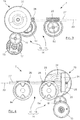
- a floating mounted caliper 1 comprises a caliper body 2 which carries a set of pads 3 and 4 on either side of a brake disc. braking 6, and which is equipped with an electromechanical actuator 7 for pressing these pads 3 and 4 against the disc 6 in braking situation.
- the plate 3 comprises a support 3a to which a lining 3b is attached.
- the plate 4 comprises a support 4a to which a lining 4b is attached.
- This electromechanical actuator 7 shown in figure 2 comprises an electric motor 13 which drives, via a drive mechanism 14, two mechanical actuators 8 and 9 arranged vis-à-vis the plate 3.
- This plate 3 extends laterally, that is to say which extends in a direction tangential to the disc 6.
- the two mechanical actuators 8 and 9 are side by side along the plate 3 extending perpendicularly to this one.
- the first actuator 8 is opposite a first portion of the plate 3 close to a first end of this plate 3 and the second mechanical actuator 9 is opposite a second portion of the plate 3 close to a second end of this plate 3.
- the first actuator 8 is mounted in a first cavity 11 of the caliper body 2 along an axis AX1 in an axial direction, that is to say in a direction normal to the brake disc 6, while the second actuator 9 is mounted in a second cavity of the caliper body 2 along an axis AX2 parallel to AX1.
- the first actuator 8 comprises a part included in the caliper body 2 with a first piston 8a which surrounds a first nut 8b screwed around a first axial driving screw 8c, and a part outside the caliper body 2 with a first helical-toothed drive wheel 8d, in other words oblique, which is rigidly secured to this first drive screw 8c.
- the first piston 8a and the first nut 8b are locked in rotation around the axis AX1 but movable in translation along this axis AX1 while the first driving screw 8c and the first driving wheel 8d are movable in rotation around the axis AX1 but blocked in translation along this same axis AX1.
- This arrangement converts a rotation of the first driving wheel 8d into an axial translation of the first piston 8a along the axis AX1, in one direction or the other depending on the direction of rotation of this first driving wheel 8d.
- the second actuator 9 comprises a second driving wheel 9d for moving a second piston 9a axially along AX2 by means of a second nut and a second driving screw, not shown.
- the first and second drive wheels 8d and 9d have reverse thread directions.
- the second actuator 9 thus converts the rotation of its driving wheel 9d into a translation of its piston 9a which is the reverse of the conversion provided by the first actuator 8. In other words, it is when the two driving wheels 8d and 9d rotate in opposite directions as the first and second piston 8a and 9a move in the same axial direction.
- the drive mechanism 14 comprises a transmission module 15 and a reduction module 16 which transmits a rotation of the motor 13, more precisely a rotation of a motor pinion 17 with oblique teeth driven directly by the motor, to the transmission module 15 with a speed lower than that of this motor pinion 17.
- the reduction module 16 comprises at input an intermediate wheel 18 with oblique toothing followed by an epicyclic gear train 19, with the intermediate wheel 18 meshed in the motor pinion 17 of axis AX3, parallel to the axes AX1 and AX2, to transmit its rotation to the epicyclic train 19.
- the epicyclic gear train 19 comprises an input sun gear 20, which is a toothed wheel with oblique teeth, in which the intermediate wheel 18 engages to make this input sun gear 20 rotate about an axis AX4 parallel to the axis AX3.
- the input sun gear 20 is extended along its axis of rotation AX4 by a planetary gear 21 with straight teeth, this sun gear 21 meshing three planet wheels 22.
- the planet wheels 22 are mounted to pivot around their axis of revolution on a planet carrier 23 mobile in rotation around the axis AX4. These satellites 22 are meshed in a fixed circular ring which surrounds them, this ring not being shown in the figures.
- the rotation of the input sun gear 20 allows the satellites 22 to rotate not only around their own axis but also with their respective axis around the axis AX4, rotating the planet carrier 23 at a speed of output much lower than the input speed.
- the planet carrier 23 is extended at the output of the epicyclic gear train 19 by an output pinion 24 with straight teeth, visible on the figure 4 , which protrudes from the center of the face of the planet carrier 23 opposite the planet wheels 22.
- the transmission module 15 comprises an angular gear wheel 26 rotating about an axis of longitudinal direction AY perpendicular to the axis AX4, this angular gear 26 being meshed in the output pinion 24.
- This arrangement converts the rotation of pinion 24 around axis AX4 into rotation of bevel gear 26 around axis AY which is perpendicular to it, otherwise called right angle transmission.
- the bevel wheel 26 has a central through hole along the axis AY which is splined to form a sliding connection of a rotary shaft 27, one end of which, which is splined in a corresponding manner, is slidably engaged in this hole.
- This sliding connection allows the angular gear 26 to drive the shaft 27 in rotation while allowing this shaft 27 to slide along AY.
- the shaft 27 extends along the axis AY in a plane parallel to the plane defined by the axes AX1 and AX2 and comprises a first and a second worm 28 and 29 which protrude fixedly from it, with the two screws endless 28 and 29 aligned along the axis AY.
- the first worm 28 is meshed with the first driving wheel 8d and the second worm 29 meshed with the second driving toothed wheel 9d.
- This arrangement converts the rotation of the shaft 27 around the axis AY into a rotation of the first and second drive wheels 8d and 9d around their respective axes AX1 and AX2, with the worms 28 and 29 integral with the shaft. 27. These rotations are in turn converted by the first and second mechanical actuators 8 and 9 in axial translation of their respective piston 8a and 9a.
- the two worm screws 28 and 29 have reverse winding directions so that a rotation of the shaft 27 in a direction marked by R on the figure 5 causes the exit of the two pistons 8a and 9a, the mechanical actuators 8 and 9 having opposite operating modes.
- a rotation of the shaft 27 in a direction opposite to the direction R causes on the contrary the retraction of the two pistons 8a and 9a.
- the portion of the plate 3 pressed here by the first actuator 8 comes to rest on the braking disc 6 before the portion pressed by the second actuator 9.
- the first piston 8a as well as the first driving wheel 8d come to a standstill , the brake disc 6 constituting an opposing force to the displacement of the portion of the pad 3 pressed by the first actuator 8.
- the motor 13 continuing to drive the shaft 27 in rotation, with the worms 28 and 29, it then causes the longitudinal translation of this shaft 27 along AY in a direction indicated by T.
- the second piston 9a bearing the portion of the plate which is not yet in contact with the disc 6 continues to progress under the combined effect of the rotation of the shaft 27 and of its translation, given that the first and second worm 28 and 29 are meshed respectively in the first and second driving wheels 8d and 9d, while the first driving wheel 8d is immobilized.
- the shaft 27 stops moving in translation but continues to rotate around its axis AY, thus allowing the force to be increased. simultaneous pads against the disc 6.
- the shaft 27 comes to a standstill once a desired torque of the drive wheels has been reached.
- a return to the initial state of the pad 3, ie to the state before braking, is allowed by a rotation of the shaft 27 but in the opposite direction to the direction R, with the same number of revolutions as those made during braking in the direction R, and a translation of the shaft in the opposite direction of T according to the same amplitude of initial displacement of T.
- the reverse rotation causes in the first place the retraction of the two pistons 8a and 9a until the piston 8a is fully retracted, then the shaft 27 moves in translation in the direction opposite to T, while retaining its rotation, until the piston 9a returns to the initial position.
- the caliper 1 makes it possible to compensate for uneven wear of the pad by associating a rotation of the worm screws with a sliding connection, ensuring that when a first portion of the pad 3 comes to rest on the disc 6, the other wafer portion can continue to move until it in turn comes to rest against the disc 6 with the desired force.
- the invention is not limited to the embodiment described of the transmission module 15 and allows the use of various and varied architectures provided that the worms are integral with one another in rotation with the toothed wheel. , and movable in translation with respect to the latter, that is to say linked to the wheel by a sliding connection.
- the rotary shaft 27' is fixed in translation by being rigidly integral with the angular gear wheel 26 ', and the worms 28' and 29 'are aligned and formed on a sleeve 31 separate from this shaft 27 '.
- the shaft 27 'and the sleeve 31 extend longitudinally along the axis AY, with the shaft 27' having external splines 32 along its extent, and the sleeve 31 surrounding this shaft 27 'and the external splines 32
- the transmission module 15 'further comprises a hub 33 extending between the shaft 27' and the sleeve 31 being rigidly linked to the sleeve 31 in its central region, that is to say between the worm screws. 28 'and 29'.
- the hub 33 is provided with internal splines 34 which engage in the external splines 32.
- the shaft 27 'and the sleeve 31, via the hub 33, are thus coupled in rotation while leaving the sleeve 31 which carries the screws 28 'and 29', a degree of freedom in translation along the axis AY with respect to the shaft 27 '.
- a return to the initial state of the plate 3 is allowed by a rotation of the assembly formed by the shaft 27 ', the hub 33 and the sleeve 31 but in the opposite direction to the direction indicated by R, with the same number of turns than those made during braking in the direction R.
- the reverse rotation first causes the retraction of the two pistons 8a and 9a until the piston 8a is fully retracted, then the sleeve 31 moves in translation in the direction opposite T, while maintaining its rotation, until the piston 9a returns to the initial position.
- the wafer portion pressed by the first actuator 8 has a lining of thickness less than that of the wafer portion pressed by the second actuator 9, but it should be noted that the invention does not only provide a solution to compensate this particular facies of wear.
- the invention could provide to do without the hub 33, with the internal splines 34 projecting directly from the sleeve 31 to engage in the external splines 32 of the shaft 27 ', thus limiting the number components of the transmission module 15 'and simplifying its assembly.
- the internal splines 34 are not necessarily formed in the central region of the sleeve 31, since they always comply with the functional condition of being meshed with the external splines 32 regardless of the state of wear of the lining. 3b.
- the invention could in particular provide that the external splines 32 do not extend over the entire extent of the shaft 27 ', since the maximum displacement of the sleeve 31 relative to the shaft 27' is limited by the two cases. for which one of the portions of garnish 3b is seine while the other portion is completely consumed.
- the shafts 27 and 27 are located “above” the first and second drive wheels 8d and 9d, with the axis AX1 located between the axes AX3 and AX4. But it should be noted that the invention could provide the shaft 27 or 27 'located “below” the driving wheels 8d and 9d, in other words with the axis AX4 closer to the axis of rotation of the brake disc. 6 than is AX1, to respect a different size.
Landscapes
- Engineering & Computer Science (AREA)
- General Engineering & Computer Science (AREA)
- Mechanical Engineering (AREA)
- Transportation (AREA)
- Braking Arrangements (AREA)
Claims (7)
- Bremssattel (1) zum Umgreifen einer Bremsscheibe (6), der einen Satz Beläge (3, 4) und ein elektromechanisches Stellglied (7) umfasst, um einen Belag (3) gegen eine Seite der Scheibe (6) zu pressen, dadurch gekennzeichnet, dass das elektromechanische Stellglied (7) umfasst:- einen Elektromotor (13), der ein erstes mechanisches Stellglied (8) und ein zweites mechanisches Stellglied (9) antreibt;- wobei das erste mechanische Stellglied (8) ein erstes Antriebszahnrad (8d) und einen ersten Kolben (8a) beinhaltet, um einen ersten Abschnitt des Belags (3) anzupressen;- wobei das zweite mechanische Stellglied (9) ein zweites Antriebszahnrad (9d) und einen zweiten beweglichen Kolben (9a) beinhaltet, um einen zweiten Abschnitt des Belags anzupressen;- wobei jedes Stellglied (8; 9) eine Drehung seines Antriebsrads (8d; 9d) in eine Translation seines Kolbens (8a; 9a) umwandelt, wobei das erste und das zweite Stellglied gegensinnige Umwandlungsrichtungen aufweisen;- ein Übertragungsmodul (15; 15'), umfassend:- eine erste Schnecke (28; 28') und eine zweite Schnecke (29; 29') mit derselben Längsrichtung (AY) und mit gegensinnigen Gangrichtungen, die zudem starr miteinander verbunden sind, wobei diese erste und zweite Schnecke (28, 29; 28', 29') mit dem ersten beziehungsweise zweiten Antriebsrad (8d, 9d) in Eingriff stehen, um sie gleichzeitig gegensinnig drehen zu lassen;- Drehantriebseinrichtungen der ersten und zweiten Schnecke (28, 29; 28', 29') durch den Elektromotor (13), wobei diese Einrichtungen eine Gleitverbindung bilden, die es der ersten und zweiten Schnecke (28, 29; 28', 29') ermöglicht, sich translatorisch entlang der Längsrichtung (AY) zu bewegen.
- Bremssattel nach Anspruch 1, bei dem die eine Gleitverbindung bildenden Drehantriebseinrichtungen der Schnecken (28, 29) des Übertragungsmoduls (15) beinhalten:- eine drehende Welle (27), die starr die erste und zweite Schnecke (28, 29) trägt, wobei diese Welle translatorisch entlang der Längsrichtung (AY) beweglich ist;- ein Zahnrad (26), das translatorisch feststeht und vom Elektromotor (13) in Drehung versetzt wird, wobei dieses Zahnrad ein keilgenutetes Durchgangsloch umfasst, in das ein keilgenutetes Ende der Welle (27) eingesetzt ist.
- Bremssattel nach Anspruch 1, bei dem die eine Gleitverbindung bildenden Drehantriebseinrichtungen der Schnecken (28', 29') des Übertragungsmoduls (15') beinhalten:- eine Hülse (31), die starr die erste und zweite Schnecke (28', 29') trägt, wobei diese Hülse (31) translatorisch entlang der Längsrichtung (AY) beweglich ist;- ein Zahnrad (26'), das translatorisch feststeht und vom Elektromotor (13) in Drehung versetzt wird;- eine drehende Welle (27), die starr mit dem Zahnrad verbunden ist und es überragt, wobei sie äußere Keilnuten (32) beinhaltet, wobei sich diese rotierende Welle (27) entlang der Längsrichtung (AY) erstreckt und von der Hülse (31) umgeben ist;- innere Keilnuten (34), die von der Hülse (31) getragen werden, mit denen die äußeren Keilnuten (32) formschlüssig in Eingriff stehen.
- Bremssattel nach Anspruch 3, bei dem die inneren Keilnuten (34) eine starr mit der Hülse (31) verbundene Nabe (33) überragen.
- Bremssattel nach einem der Ansprüche 1 bis 4, bei dem das erste und zweite Antriebsrad (8d, 9d) schrägverzahnt sind und um parallel zueinander und senkrecht zur Längsrichtung (AY) verlaufende Achsen drehen.
- Bremssattel nach einem der vorhergehenden Ansprüche, umfassend ein Getriebemodul (16), das die Drehung des Motors (13) an die Drehantriebseinrichtungen der ersten und zweiten Schnecke (28; 29/28'; 29') überträgt.
- Scheibenbremse mit einem Bremssattel (1) nach einem der vorhergehenden Ansprüche.
Applications Claiming Priority (2)
| Application Number | Priority Date | Filing Date | Title |
|---|---|---|---|
| FR1761163A FR3074243B1 (fr) | 2017-11-24 | 2017-11-24 | Etrier de frein a disque de type electromecanique comprenant deux actionneurs mecaniques pour compenser une usure inegale d'une meme plaquette |
| PCT/FR2018/052920 WO2019102133A1 (fr) | 2017-11-24 | 2018-11-20 | Etrier de frein a disque de type electromecanique comprenant deux actionneurs mecaniques pour compenser une usure inégale d'une même plaquette |
Publications (2)
| Publication Number | Publication Date |
|---|---|
| EP3676144A1 EP3676144A1 (de) | 2020-07-08 |
| EP3676144B1 true EP3676144B1 (de) | 2021-06-30 |
Family
ID=60765955
Family Applications (1)
| Application Number | Title | Priority Date | Filing Date |
|---|---|---|---|
| EP18819195.1A Active EP3676144B1 (de) | 2017-11-24 | 2018-11-20 | Elektromechanisches bremssattel mit zwei aktuatoren, die für ungleichmässigen bremsbelagverschleiss kompensiert |
Country Status (4)
| Country | Link |
|---|---|
| US (1) | US11535225B2 (de) |
| EP (1) | EP3676144B1 (de) |
| FR (1) | FR3074243B1 (de) |
| WO (1) | WO2019102133A1 (de) |
Cited By (1)
| Publication number | Priority date | Publication date | Assignee | Title |
|---|---|---|---|---|
| EP4570605A1 (de) * | 2023-12-14 | 2025-06-18 | Huawei Digital Power Technologies Co., Ltd. | Elektromechanische bremsvorrichtung mit versetzter getriebewelle eines untersetzungsgetriebes, system und fahrzeug |
Families Citing this family (16)
| Publication number | Priority date | Publication date | Assignee | Title |
|---|---|---|---|---|
| KR102684348B1 (ko) * | 2019-07-16 | 2024-07-12 | 현대모비스 주식회사 | 차량용 주차 브레이크 장치 |
| KR102690944B1 (ko) * | 2019-07-16 | 2024-08-01 | 현대모비스 주식회사 | 차량용 주차 브레이크 장치 |
| KR102718510B1 (ko) * | 2019-07-16 | 2024-10-22 | 현대모비스 주식회사 | 차량용 주차 브레이크 장치 |
| KR102691381B1 (ko) * | 2019-07-16 | 2024-08-05 | 현대모비스 주식회사 | 차량용 주차 브레이크 장치 |
| KR102644871B1 (ko) * | 2019-07-16 | 2024-03-07 | 현대모비스 주식회사 | 차량용 주차 브레이크 장치 |
| US11420606B2 (en) * | 2019-07-16 | 2022-08-23 | Hyundai Mobis Co., Ltd. | Parking brake apparatus for vehicle |
| CN112238851B (zh) * | 2019-07-16 | 2023-03-14 | 现代摩比斯株式会社 | 用于车辆的驻车制动设备 |
| CN112298126B (zh) * | 2019-08-01 | 2024-04-16 | 汉拿万都株式会社 | 一种车辆卡钳、车辆的制动方法及车辆 |
| KR102767291B1 (ko) * | 2020-05-18 | 2025-02-17 | 현대자동차주식회사 | 듀얼 엑츄에이터로 구성된 자율 주행 차량용 전동식 부스터 |
| CN114655177A (zh) * | 2020-12-23 | 2022-06-24 | 沃尔沃汽车公司 | 机动车制动系统及其操作方法 |
| JP7597654B6 (ja) * | 2021-06-08 | 2025-01-06 | 曙ブレーキ工業株式会社 | ディスクブレーキ装置用モータギヤユニット及びディスクブレーキ装置 |
| CN113790231B (zh) * | 2021-11-13 | 2022-02-11 | 杭州丹佛斯科技有限公司 | 一种防磨损新能源汽车刹车机构 |
| FR3130002B1 (fr) * | 2021-12-03 | 2023-10-27 | Hitachi Astemo France | Système de freinage à désengagement sécurisé |
| KR20240153843A (ko) | 2023-04-17 | 2024-10-24 | 현대모비스 주식회사 | 브레이크 장치 |
| DE102023212550A1 (de) | 2023-12-12 | 2025-06-12 | Robert Bosch Gesellschaft mit beschränkter Haftung | Elektromechanische Bremse mit zwei Spindeltriebeinheiten |
| DE102024204112A1 (de) | 2024-05-02 | 2025-11-06 | Robert Bosch Gesellschaft mit beschränkter Haftung | Elektromechanische Bremse mit Versatz zwischen Antriebswelle und Schneckenwelle |
Family Cites Families (8)
| Publication number | Priority date | Publication date | Assignee | Title |
|---|---|---|---|---|
| US9353811B2 (en) * | 2013-11-13 | 2016-05-31 | Akebono Brake Industry Co., Ltd | Electric park brake for a multiple piston caliper |
| FR3033378B1 (fr) | 2015-03-06 | 2018-08-10 | Foundation Brakes France | "frein a disque comportant au moins un ressort de rappel elastique d'un patin de freinage, ressort de rappel elastique, glissiere de guidage et kit de remplacement" |
| US9587692B2 (en) * | 2015-04-01 | 2017-03-07 | Akebono Brake Industry Co., Ltd | Differential for a parking brake assembly |
| FR3045758B1 (fr) | 2015-12-21 | 2018-01-05 | Foundation Brakes France | Frein a disque electromecanique comprenant une transmission compensant une usure inegale d'une meme plaquette |
| FR3045757B1 (fr) * | 2015-12-21 | 2018-06-29 | Foundation Brakes France | Frein a disque electromecanique a etrier fixe comprenant une transmission compensant une usure asymetrique de ses plaquettes |
| US9989114B2 (en) * | 2016-06-24 | 2018-06-05 | Akebono Brake Industry Co., Ltd | Power transfer mechanism for a parking brake assembly |
| KR102022403B1 (ko) * | 2018-01-17 | 2019-09-18 | 현대모비스 주식회사 | 차량용 브레이크 장치 |
| KR102680873B1 (ko) * | 2019-10-25 | 2024-07-03 | 현대모비스 주식회사 | 차량용 주차 브레이크 장치 |
-
2017
- 2017-11-24 FR FR1761163A patent/FR3074243B1/fr active Active
-
2018
- 2018-11-20 US US16/766,377 patent/US11535225B2/en active Active
- 2018-11-20 EP EP18819195.1A patent/EP3676144B1/de active Active
- 2018-11-20 WO PCT/FR2018/052920 patent/WO2019102133A1/fr not_active Ceased
Cited By (1)
| Publication number | Priority date | Publication date | Assignee | Title |
|---|---|---|---|---|
| EP4570605A1 (de) * | 2023-12-14 | 2025-06-18 | Huawei Digital Power Technologies Co., Ltd. | Elektromechanische bremsvorrichtung mit versetzter getriebewelle eines untersetzungsgetriebes, system und fahrzeug |
Also Published As
| Publication number | Publication date |
|---|---|
| FR3074243A1 (fr) | 2019-05-31 |
| US20200361437A1 (en) | 2020-11-19 |
| EP3676144A1 (de) | 2020-07-08 |
| US11535225B2 (en) | 2022-12-27 |
| FR3074243B1 (fr) | 2019-12-27 |
| WO2019102133A1 (fr) | 2019-05-31 |
Similar Documents
| Publication | Publication Date | Title |
|---|---|---|
| EP3676144B1 (de) | Elektromechanisches bremssattel mit zwei aktuatoren, die für ungleichmässigen bremsbelagverschleiss kompensiert | |
| EP3089901B1 (de) | Planetenreduktionsgetriebe, trommel- und scheibenbremse und bremsvorrichtung mit so einem planetenreduktionsgetriebe | |
| EP3394464B1 (de) | Elektromechanische scheibenbremse mit festem bremssattel mit einem getriebe zur kompensierung von asymmetrischem verschleiss der beläge davon | |
| EP3089899B1 (de) | Aktuator mit schienengesteruerter getreibe, trommelbremse und bremsanordnung mit so einem aktuator | |
| FR2999673A1 (fr) | "porte-satellites pour un actionneur electromecanique de frein de stationnement, actionneur et procedes d'assemblage" | |
| EP3175146B1 (de) | Drehmomentuntersetzungsgetriebe | |
| EP3394463B1 (de) | Elektromechanische scheibenbremse mit einem getriebe zum ausgleich von ungleichmässigem verschleiss am belag | |
| EP3175136B1 (de) | Fahrzeugbremsenbetätiger | |
| EP3089900B1 (de) | Getriebeuntersetzung mit elektromotor für eine trommelbremse | |
| EP3087286B1 (de) | Scheibenbremse mit einer parkbremse mit hydraulischer betätigung | |
| EP3902727B1 (de) | Untersetzungsmotor für trommelbremse | |
| EP3087288B1 (de) | Scheibenbremse mit hydraulischer steuerung mit einer feststellbremse mit hydraulischer betätigung | |
| WO2025078665A1 (fr) | Frein à disque, notamment pour véhicule automobile | |
| EP3087289B1 (de) | Verbesserte scheibenbremse mit einer hydraulisch betätigten feststellbremse | |
| FR3148064A1 (fr) | Frein a disque electromécanique à compacité augmentée | |
| EP4559767A1 (de) | Scheibenbremse, insbesondere für ein kraftfahrzeug | |
| EP3087287B1 (de) | Scheibenbremse mit einer feststellbremse mit hydraulischer betätigung und verschleissnachstelleinheit | |
| FR3097021A1 (fr) | Reducteur et motoreducteur pour frein a débrayage intégré | |
| WO2020244936A1 (fr) | Motoreducteur pour actionneur de frein a tambour, comprenant un taux de reduction de 30 a 210 | |
| FR2880083A1 (fr) | Montage a roulement avec piste de roulement integree |
Legal Events
| Date | Code | Title | Description |
|---|---|---|---|
| STAA | Information on the status of an ep patent application or granted ep patent |
Free format text: STATUS: UNKNOWN |
|
| STAA | Information on the status of an ep patent application or granted ep patent |
Free format text: STATUS: THE INTERNATIONAL PUBLICATION HAS BEEN MADE |
|
| PUAI | Public reference made under article 153(3) epc to a published international application that has entered the european phase |
Free format text: ORIGINAL CODE: 0009012 |
|
| STAA | Information on the status of an ep patent application or granted ep patent |
Free format text: STATUS: REQUEST FOR EXAMINATION WAS MADE |
|
| 17P | Request for examination filed |
Effective date: 20200403 |
|
| AK | Designated contracting states |
Kind code of ref document: A1 Designated state(s): AL AT BE BG CH CY CZ DE DK EE ES FI FR GB GR HR HU IE IS IT LI LT LU LV MC MK MT NL NO PL PT RO RS SE SI SK SM TR |
|
| AX | Request for extension of the european patent |
Extension state: BA ME |
|
| RIN1 | Information on inventor provided before grant (corrected) |
Inventor name: MOUMANE, MEHDI Inventor name: LABARRE, XAVIER Inventor name: ESNEE, DIDIER |
|
| GRAP | Despatch of communication of intention to grant a patent |
Free format text: ORIGINAL CODE: EPIDOSNIGR1 |
|
| STAA | Information on the status of an ep patent application or granted ep patent |
Free format text: STATUS: GRANT OF PATENT IS INTENDED |
|
| INTG | Intention to grant announced |
Effective date: 20210122 |
|
| DAV | Request for validation of the european patent (deleted) | ||
| DAX | Request for extension of the european patent (deleted) | ||
| GRAS | Grant fee paid |
Free format text: ORIGINAL CODE: EPIDOSNIGR3 |
|
| GRAA | (expected) grant |
Free format text: ORIGINAL CODE: 0009210 |
|
| STAA | Information on the status of an ep patent application or granted ep patent |
Free format text: STATUS: THE PATENT HAS BEEN GRANTED |
|
| AK | Designated contracting states |
Kind code of ref document: B1 Designated state(s): AL AT BE BG CH CY CZ DE DK EE ES FI FR GB GR HR HU IE IS IT LI LT LU LV MC MK MT NL NO PL PT RO RS SE SI SK SM TR |
|
| REG | Reference to a national code |
Ref country code: CH Ref legal event code: EP |
|
| REG | Reference to a national code |
Ref country code: DE Ref legal event code: R096 Ref document number: 602018019501 Country of ref document: DE Ref country code: AT Ref legal event code: REF Ref document number: 1406102 Country of ref document: AT Kind code of ref document: T Effective date: 20210715 |
|
| REG | Reference to a national code |
Ref country code: IE Ref legal event code: FG4D Free format text: LANGUAGE OF EP DOCUMENT: FRENCH |
|
| REG | Reference to a national code |
Ref country code: LT Ref legal event code: MG9D |
|
| RAP4 | Party data changed (patent owner data changed or rights of a patent transferred) |
Owner name: HITACHI ASTEMO FRANCE |
|
| PG25 | Lapsed in a contracting state [announced via postgrant information from national office to epo] |
Ref country code: FI Free format text: LAPSE BECAUSE OF FAILURE TO SUBMIT A TRANSLATION OF THE DESCRIPTION OR TO PAY THE FEE WITHIN THE PRESCRIBED TIME-LIMIT Effective date: 20210630 Ref country code: HR Free format text: LAPSE BECAUSE OF FAILURE TO SUBMIT A TRANSLATION OF THE DESCRIPTION OR TO PAY THE FEE WITHIN THE PRESCRIBED TIME-LIMIT Effective date: 20210630 Ref country code: BG Free format text: LAPSE BECAUSE OF FAILURE TO SUBMIT A TRANSLATION OF THE DESCRIPTION OR TO PAY THE FEE WITHIN THE PRESCRIBED TIME-LIMIT Effective date: 20210930 |
|
| REG | Reference to a national code |
Ref country code: NL Ref legal event code: MP Effective date: 20210630 |
|
| REG | Reference to a national code |
Ref country code: AT Ref legal event code: MK05 Ref document number: 1406102 Country of ref document: AT Kind code of ref document: T Effective date: 20210630 |
|
| PG25 | Lapsed in a contracting state [announced via postgrant information from national office to epo] |
Ref country code: GR Free format text: LAPSE BECAUSE OF FAILURE TO SUBMIT A TRANSLATION OF THE DESCRIPTION OR TO PAY THE FEE WITHIN THE PRESCRIBED TIME-LIMIT Effective date: 20211001 Ref country code: LV Free format text: LAPSE BECAUSE OF FAILURE TO SUBMIT A TRANSLATION OF THE DESCRIPTION OR TO PAY THE FEE WITHIN THE PRESCRIBED TIME-LIMIT Effective date: 20210630 Ref country code: NO Free format text: LAPSE BECAUSE OF FAILURE TO SUBMIT A TRANSLATION OF THE DESCRIPTION OR TO PAY THE FEE WITHIN THE PRESCRIBED TIME-LIMIT Effective date: 20210930 Ref country code: RS Free format text: LAPSE BECAUSE OF FAILURE TO SUBMIT A TRANSLATION OF THE DESCRIPTION OR TO PAY THE FEE WITHIN THE PRESCRIBED TIME-LIMIT Effective date: 20210630 Ref country code: SE Free format text: LAPSE BECAUSE OF FAILURE TO SUBMIT A TRANSLATION OF THE DESCRIPTION OR TO PAY THE FEE WITHIN THE PRESCRIBED TIME-LIMIT Effective date: 20210630 |
|
| PG25 | Lapsed in a contracting state [announced via postgrant information from national office to epo] |
Ref country code: SK Free format text: LAPSE BECAUSE OF FAILURE TO SUBMIT A TRANSLATION OF THE DESCRIPTION OR TO PAY THE FEE WITHIN THE PRESCRIBED TIME-LIMIT Effective date: 20210630 Ref country code: EE Free format text: LAPSE BECAUSE OF FAILURE TO SUBMIT A TRANSLATION OF THE DESCRIPTION OR TO PAY THE FEE WITHIN THE PRESCRIBED TIME-LIMIT Effective date: 20210630 Ref country code: ES Free format text: LAPSE BECAUSE OF FAILURE TO SUBMIT A TRANSLATION OF THE DESCRIPTION OR TO PAY THE FEE WITHIN THE PRESCRIBED TIME-LIMIT Effective date: 20210630 Ref country code: RO Free format text: LAPSE BECAUSE OF FAILURE TO SUBMIT A TRANSLATION OF THE DESCRIPTION OR TO PAY THE FEE WITHIN THE PRESCRIBED TIME-LIMIT Effective date: 20210630 Ref country code: NL Free format text: LAPSE BECAUSE OF FAILURE TO SUBMIT A TRANSLATION OF THE DESCRIPTION OR TO PAY THE FEE WITHIN THE PRESCRIBED TIME-LIMIT Effective date: 20210630 Ref country code: PT Free format text: LAPSE BECAUSE OF FAILURE TO SUBMIT A TRANSLATION OF THE DESCRIPTION OR TO PAY THE FEE WITHIN THE PRESCRIBED TIME-LIMIT Effective date: 20211102 Ref country code: SM Free format text: LAPSE BECAUSE OF FAILURE TO SUBMIT A TRANSLATION OF THE DESCRIPTION OR TO PAY THE FEE WITHIN THE PRESCRIBED TIME-LIMIT Effective date: 20210630 Ref country code: CZ Free format text: LAPSE BECAUSE OF FAILURE TO SUBMIT A TRANSLATION OF THE DESCRIPTION OR TO PAY THE FEE WITHIN THE PRESCRIBED TIME-LIMIT Effective date: 20210630 Ref country code: AT Free format text: LAPSE BECAUSE OF FAILURE TO SUBMIT A TRANSLATION OF THE DESCRIPTION OR TO PAY THE FEE WITHIN THE PRESCRIBED TIME-LIMIT Effective date: 20210630 |
|
| PG25 | Lapsed in a contracting state [announced via postgrant information from national office to epo] |
Ref country code: PL Free format text: LAPSE BECAUSE OF FAILURE TO SUBMIT A TRANSLATION OF THE DESCRIPTION OR TO PAY THE FEE WITHIN THE PRESCRIBED TIME-LIMIT Effective date: 20210630 |
|
| REG | Reference to a national code |
Ref country code: DE Ref legal event code: R097 Ref document number: 602018019501 Country of ref document: DE |
|
| PG25 | Lapsed in a contracting state [announced via postgrant information from national office to epo] |
Ref country code: DK Free format text: LAPSE BECAUSE OF FAILURE TO SUBMIT A TRANSLATION OF THE DESCRIPTION OR TO PAY THE FEE WITHIN THE PRESCRIBED TIME-LIMIT Effective date: 20210630 |
|
| PLBE | No opposition filed within time limit |
Free format text: ORIGINAL CODE: 0009261 |
|
| STAA | Information on the status of an ep patent application or granted ep patent |
Free format text: STATUS: NO OPPOSITION FILED WITHIN TIME LIMIT |
|
| PG25 | Lapsed in a contracting state [announced via postgrant information from national office to epo] |
Ref country code: AL Free format text: LAPSE BECAUSE OF FAILURE TO SUBMIT A TRANSLATION OF THE DESCRIPTION OR TO PAY THE FEE WITHIN THE PRESCRIBED TIME-LIMIT Effective date: 20210630 |
|
| 26N | No opposition filed |
Effective date: 20220331 |
|
| PG25 | Lapsed in a contracting state [announced via postgrant information from national office to epo] |
Ref country code: MC Free format text: LAPSE BECAUSE OF FAILURE TO SUBMIT A TRANSLATION OF THE DESCRIPTION OR TO PAY THE FEE WITHIN THE PRESCRIBED TIME-LIMIT Effective date: 20210630 |
|
| REG | Reference to a national code |
Ref country code: CH Ref legal event code: PL |
|
| PG25 | Lapsed in a contracting state [announced via postgrant information from national office to epo] |
Ref country code: LU Free format text: LAPSE BECAUSE OF NON-PAYMENT OF DUE FEES Effective date: 20211120 Ref country code: IT Free format text: LAPSE BECAUSE OF FAILURE TO SUBMIT A TRANSLATION OF THE DESCRIPTION OR TO PAY THE FEE WITHIN THE PRESCRIBED TIME-LIMIT Effective date: 20210630 Ref country code: BE Free format text: LAPSE BECAUSE OF NON-PAYMENT OF DUE FEES Effective date: 20211130 |
|
| REG | Reference to a national code |
Ref country code: BE Ref legal event code: MM Effective date: 20211130 |
|
| PG25 | Lapsed in a contracting state [announced via postgrant information from national office to epo] |
Ref country code: LI Free format text: LAPSE BECAUSE OF NON-PAYMENT OF DUE FEES Effective date: 20211130 Ref country code: CH Free format text: LAPSE BECAUSE OF NON-PAYMENT OF DUE FEES Effective date: 20211130 |
|
| PG25 | Lapsed in a contracting state [announced via postgrant information from national office to epo] |
Ref country code: IE Free format text: LAPSE BECAUSE OF NON-PAYMENT OF DUE FEES Effective date: 20211120 |
|
| PG25 | Lapsed in a contracting state [announced via postgrant information from national office to epo] |
Ref country code: LT Free format text: LAPSE BECAUSE OF FAILURE TO SUBMIT A TRANSLATION OF THE DESCRIPTION OR TO PAY THE FEE WITHIN THE PRESCRIBED TIME-LIMIT Effective date: 20210630 |
|
| PG25 | Lapsed in a contracting state [announced via postgrant information from national office to epo] |
Ref country code: CY Free format text: LAPSE BECAUSE OF FAILURE TO SUBMIT A TRANSLATION OF THE DESCRIPTION OR TO PAY THE FEE WITHIN THE PRESCRIBED TIME-LIMIT Effective date: 20210630 |
|
| GBPC | Gb: european patent ceased through non-payment of renewal fee |
Effective date: 20221120 |
|
| PG25 | Lapsed in a contracting state [announced via postgrant information from national office to epo] |
Ref country code: HU Free format text: LAPSE BECAUSE OF FAILURE TO SUBMIT A TRANSLATION OF THE DESCRIPTION OR TO PAY THE FEE WITHIN THE PRESCRIBED TIME-LIMIT; INVALID AB INITIO Effective date: 20181120 |
|
| PG25 | Lapsed in a contracting state [announced via postgrant information from national office to epo] |
Ref country code: GB Free format text: LAPSE BECAUSE OF NON-PAYMENT OF DUE FEES Effective date: 20221120 |
|
| PG25 | Lapsed in a contracting state [announced via postgrant information from national office to epo] |
Ref country code: MK Free format text: LAPSE BECAUSE OF FAILURE TO SUBMIT A TRANSLATION OF THE DESCRIPTION OR TO PAY THE FEE WITHIN THE PRESCRIBED TIME-LIMIT Effective date: 20210630 |
|
| PG25 | Lapsed in a contracting state [announced via postgrant information from national office to epo] |
Ref country code: TR Free format text: LAPSE BECAUSE OF FAILURE TO SUBMIT A TRANSLATION OF THE DESCRIPTION OR TO PAY THE FEE WITHIN THE PRESCRIBED TIME-LIMIT Effective date: 20210630 |
|
| PG25 | Lapsed in a contracting state [announced via postgrant information from national office to epo] |
Ref country code: MT Free format text: LAPSE BECAUSE OF FAILURE TO SUBMIT A TRANSLATION OF THE DESCRIPTION OR TO PAY THE FEE WITHIN THE PRESCRIBED TIME-LIMIT Effective date: 20210630 |
|
| PGFP | Annual fee paid to national office [announced via postgrant information from national office to epo] |
Ref country code: DE Payment date: 20251022 Year of fee payment: 8 |
|
| PGFP | Annual fee paid to national office [announced via postgrant information from national office to epo] |
Ref country code: FR Payment date: 20251022 Year of fee payment: 8 |