EP3674730A1 - Battery diagnostic device and method - Google Patents
Battery diagnostic device and method Download PDFInfo
- Publication number
- EP3674730A1 EP3674730A1 EP19785913.5A EP19785913A EP3674730A1 EP 3674730 A1 EP3674730 A1 EP 3674730A1 EP 19785913 A EP19785913 A EP 19785913A EP 3674730 A1 EP3674730 A1 EP 3674730A1
- Authority
- EP
- European Patent Office
- Prior art keywords
- region
- battery
- soc
- size
- processor
- Prior art date
- Legal status (The legal status is an assumption and is not a legal conclusion. Google has not performed a legal analysis and makes no representation as to the accuracy of the status listed.)
- Granted
Links
- 238000000034 method Methods 0.000 title description 18
- 230000008859 change Effects 0.000 claims abstract description 244
- 239000011149 active material Substances 0.000 claims abstract description 65
- 238000003745 diagnosis Methods 0.000 claims abstract description 14
- 238000002405 diagnostic procedure Methods 0.000 claims description 5
- 230000003247 decreasing effect Effects 0.000 description 16
- 230000006870 function Effects 0.000 description 11
- 230000008569 process Effects 0.000 description 9
- 238000010586 diagram Methods 0.000 description 8
- 230000015556 catabolic process Effects 0.000 description 7
- 238000006731 degradation reaction Methods 0.000 description 7
- 238000004891 communication Methods 0.000 description 5
- WHXSMMKQMYFTQS-UHFFFAOYSA-N Lithium Chemical compound [Li] WHXSMMKQMYFTQS-UHFFFAOYSA-N 0.000 description 4
- 230000007423 decrease Effects 0.000 description 4
- 229910052744 lithium Inorganic materials 0.000 description 4
- 238000012986 modification Methods 0.000 description 4
- 230000004048 modification Effects 0.000 description 4
- 230000007850 degeneration Effects 0.000 description 3
- 238000009499 grossing Methods 0.000 description 3
- 230000001419 dependent effect Effects 0.000 description 2
- 238000001514 detection method Methods 0.000 description 2
- 238000007599 discharging Methods 0.000 description 2
- 230000010354 integration Effects 0.000 description 2
- 238000013507 mapping Methods 0.000 description 2
- 238000005259 measurement Methods 0.000 description 2
- 238000012545 processing Methods 0.000 description 2
- 239000004065 semiconductor Substances 0.000 description 2
- NDVLTYZPCACLMA-UHFFFAOYSA-N silver oxide Chemical compound [O-2].[Ag+].[Ag+] NDVLTYZPCACLMA-UHFFFAOYSA-N 0.000 description 2
- 239000000126 substance Substances 0.000 description 2
- VNDYJBBGRKZCSX-UHFFFAOYSA-L zinc bromide Chemical compound Br[Zn]Br VNDYJBBGRKZCSX-UHFFFAOYSA-L 0.000 description 2
- 239000002253 acid Substances 0.000 description 1
- OJIJEKBXJYRIBZ-UHFFFAOYSA-N cadmium nickel Chemical compound [Ni].[Cd] OJIJEKBXJYRIBZ-UHFFFAOYSA-N 0.000 description 1
- 230000001413 cellular effect Effects 0.000 description 1
- 238000007796 conventional method Methods 0.000 description 1
- 238000013461 design Methods 0.000 description 1
- 230000000694 effects Effects 0.000 description 1
- 230000005611 electricity Effects 0.000 description 1
- 238000003487 electrochemical reaction Methods 0.000 description 1
- 239000003792 electrolyte Substances 0.000 description 1
- 238000006056 electrooxidation reaction Methods 0.000 description 1
- 238000004146 energy storage Methods 0.000 description 1
- 150000002500 ions Chemical class 0.000 description 1
- UGKDIUIOSMUOAW-UHFFFAOYSA-N iron nickel Chemical compound [Fe].[Ni] UGKDIUIOSMUOAW-UHFFFAOYSA-N 0.000 description 1
- 229910052987 metal hydride Inorganic materials 0.000 description 1
- 229910052759 nickel Inorganic materials 0.000 description 1
- PXHVJJICTQNCMI-UHFFFAOYSA-N nickel Substances [Ni] PXHVJJICTQNCMI-UHFFFAOYSA-N 0.000 description 1
- -1 nickel metal hydride Chemical class 0.000 description 1
- QELJHCBNGDEXLD-UHFFFAOYSA-N nickel zinc Chemical compound [Ni].[Zn] QELJHCBNGDEXLD-UHFFFAOYSA-N 0.000 description 1
- 230000003287 optical effect Effects 0.000 description 1
- 238000007747 plating Methods 0.000 description 1
- 229920000642 polymer Polymers 0.000 description 1
- 238000006722 reduction reaction Methods 0.000 description 1
- 230000002441 reversible effect Effects 0.000 description 1
- 229910001923 silver oxide Inorganic materials 0.000 description 1
- 238000006467 substitution reaction Methods 0.000 description 1
- 230000008961 swelling Effects 0.000 description 1
- 238000012546 transfer Methods 0.000 description 1
- 229940102001 zinc bromide Drugs 0.000 description 1
- SZKTYYIADWRVSA-UHFFFAOYSA-N zinc manganese(2+) oxygen(2-) Chemical compound [O--].[O--].[Mn++].[Zn++] SZKTYYIADWRVSA-UHFFFAOYSA-N 0.000 description 1
Images


Classifications
-
- G—PHYSICS
- G01—MEASURING; TESTING
- G01R—MEASURING ELECTRIC VARIABLES; MEASURING MAGNETIC VARIABLES
- G01R31/00—Arrangements for testing electric properties; Arrangements for locating electric faults; Arrangements for electrical testing characterised by what is being tested not provided for elsewhere
- G01R31/36—Arrangements for testing, measuring or monitoring the electrical condition of accumulators or electric batteries, e.g. capacity or state of charge [SoC]
- G01R31/367—Software therefor, e.g. for battery testing using modelling or look-up tables
-
- B—PERFORMING OPERATIONS; TRANSPORTING
- B60—VEHICLES IN GENERAL
- B60L—PROPULSION OF ELECTRICALLY-PROPELLED VEHICLES; SUPPLYING ELECTRIC POWER FOR AUXILIARY EQUIPMENT OF ELECTRICALLY-PROPELLED VEHICLES; ELECTRODYNAMIC BRAKE SYSTEMS FOR VEHICLES IN GENERAL; MAGNETIC SUSPENSION OR LEVITATION FOR VEHICLES; MONITORING OPERATING VARIABLES OF ELECTRICALLY-PROPELLED VEHICLES; ELECTRIC SAFETY DEVICES FOR ELECTRICALLY-PROPELLED VEHICLES
- B60L3/00—Electric devices on electrically-propelled vehicles for safety purposes; Monitoring operating variables, e.g. speed, deceleration or energy consumption
- B60L3/0023—Detecting, eliminating, remedying or compensating for drive train abnormalities, e.g. failures within the drive train
- B60L3/0046—Detecting, eliminating, remedying or compensating for drive train abnormalities, e.g. failures within the drive train relating to electric energy storage systems, e.g. batteries or capacitors
-
- B—PERFORMING OPERATIONS; TRANSPORTING
- B60—VEHICLES IN GENERAL
- B60L—PROPULSION OF ELECTRICALLY-PROPELLED VEHICLES; SUPPLYING ELECTRIC POWER FOR AUXILIARY EQUIPMENT OF ELECTRICALLY-PROPELLED VEHICLES; ELECTRODYNAMIC BRAKE SYSTEMS FOR VEHICLES IN GENERAL; MAGNETIC SUSPENSION OR LEVITATION FOR VEHICLES; MONITORING OPERATING VARIABLES OF ELECTRICALLY-PROPELLED VEHICLES; ELECTRIC SAFETY DEVICES FOR ELECTRICALLY-PROPELLED VEHICLES
- B60L3/00—Electric devices on electrically-propelled vehicles for safety purposes; Monitoring operating variables, e.g. speed, deceleration or energy consumption
- B60L3/12—Recording operating variables ; Monitoring of operating variables
-
- B—PERFORMING OPERATIONS; TRANSPORTING
- B60—VEHICLES IN GENERAL
- B60L—PROPULSION OF ELECTRICALLY-PROPELLED VEHICLES; SUPPLYING ELECTRIC POWER FOR AUXILIARY EQUIPMENT OF ELECTRICALLY-PROPELLED VEHICLES; ELECTRODYNAMIC BRAKE SYSTEMS FOR VEHICLES IN GENERAL; MAGNETIC SUSPENSION OR LEVITATION FOR VEHICLES; MONITORING OPERATING VARIABLES OF ELECTRICALLY-PROPELLED VEHICLES; ELECTRIC SAFETY DEVICES FOR ELECTRICALLY-PROPELLED VEHICLES
- B60L58/00—Methods or circuit arrangements for monitoring or controlling batteries or fuel cells, specially adapted for electric vehicles
- B60L58/10—Methods or circuit arrangements for monitoring or controlling batteries or fuel cells, specially adapted for electric vehicles for monitoring or controlling batteries
- B60L58/12—Methods or circuit arrangements for monitoring or controlling batteries or fuel cells, specially adapted for electric vehicles for monitoring or controlling batteries responding to state of charge [SoC]
-
- B—PERFORMING OPERATIONS; TRANSPORTING
- B60—VEHICLES IN GENERAL
- B60L—PROPULSION OF ELECTRICALLY-PROPELLED VEHICLES; SUPPLYING ELECTRIC POWER FOR AUXILIARY EQUIPMENT OF ELECTRICALLY-PROPELLED VEHICLES; ELECTRODYNAMIC BRAKE SYSTEMS FOR VEHICLES IN GENERAL; MAGNETIC SUSPENSION OR LEVITATION FOR VEHICLES; MONITORING OPERATING VARIABLES OF ELECTRICALLY-PROPELLED VEHICLES; ELECTRIC SAFETY DEVICES FOR ELECTRICALLY-PROPELLED VEHICLES
- B60L58/00—Methods or circuit arrangements for monitoring or controlling batteries or fuel cells, specially adapted for electric vehicles
- B60L58/10—Methods or circuit arrangements for monitoring or controlling batteries or fuel cells, specially adapted for electric vehicles for monitoring or controlling batteries
- B60L58/16—Methods or circuit arrangements for monitoring or controlling batteries or fuel cells, specially adapted for electric vehicles for monitoring or controlling batteries responding to battery ageing, e.g. to the number of charging cycles or the state of health [SoH]
-
- G—PHYSICS
- G01—MEASURING; TESTING
- G01R—MEASURING ELECTRIC VARIABLES; MEASURING MAGNETIC VARIABLES
- G01R19/00—Arrangements for measuring currents or voltages or for indicating presence or sign thereof
- G01R19/12—Measuring rate of change
-
- G—PHYSICS
- G01—MEASURING; TESTING
- G01R—MEASURING ELECTRIC VARIABLES; MEASURING MAGNETIC VARIABLES
- G01R31/00—Arrangements for testing electric properties; Arrangements for locating electric faults; Arrangements for electrical testing characterised by what is being tested not provided for elsewhere
- G01R31/36—Arrangements for testing, measuring or monitoring the electrical condition of accumulators or electric batteries, e.g. capacity or state of charge [SoC]
- G01R31/3644—Constructional arrangements
- G01R31/3648—Constructional arrangements comprising digital calculation means, e.g. for performing an algorithm
-
- G—PHYSICS
- G01—MEASURING; TESTING
- G01R—MEASURING ELECTRIC VARIABLES; MEASURING MAGNETIC VARIABLES
- G01R31/00—Arrangements for testing electric properties; Arrangements for locating electric faults; Arrangements for electrical testing characterised by what is being tested not provided for elsewhere
- G01R31/36—Arrangements for testing, measuring or monitoring the electrical condition of accumulators or electric batteries, e.g. capacity or state of charge [SoC]
- G01R31/382—Arrangements for monitoring battery or accumulator variables, e.g. SoC
- G01R31/3842—Arrangements for monitoring battery or accumulator variables, e.g. SoC combining voltage and current measurements
-
- G—PHYSICS
- G01—MEASURING; TESTING
- G01R—MEASURING ELECTRIC VARIABLES; MEASURING MAGNETIC VARIABLES
- G01R31/00—Arrangements for testing electric properties; Arrangements for locating electric faults; Arrangements for electrical testing characterised by what is being tested not provided for elsewhere
- G01R31/36—Arrangements for testing, measuring or monitoring the electrical condition of accumulators or electric batteries, e.g. capacity or state of charge [SoC]
- G01R31/392—Determining battery ageing or deterioration, e.g. state of health
-
- H—ELECTRICITY
- H01—ELECTRIC ELEMENTS
- H01M—PROCESSES OR MEANS, e.g. BATTERIES, FOR THE DIRECT CONVERSION OF CHEMICAL ENERGY INTO ELECTRICAL ENERGY
- H01M10/00—Secondary cells; Manufacture thereof
- H01M10/42—Methods or arrangements for servicing or maintenance of secondary cells or secondary half-cells
- H01M10/425—Structural combination with electronic components, e.g. electronic circuits integrated to the outside of the casing
-
- H—ELECTRICITY
- H01—ELECTRIC ELEMENTS
- H01M—PROCESSES OR MEANS, e.g. BATTERIES, FOR THE DIRECT CONVERSION OF CHEMICAL ENERGY INTO ELECTRICAL ENERGY
- H01M10/00—Secondary cells; Manufacture thereof
- H01M10/42—Methods or arrangements for servicing or maintenance of secondary cells or secondary half-cells
- H01M10/4285—Testing apparatus
-
- H—ELECTRICITY
- H01—ELECTRIC ELEMENTS
- H01M—PROCESSES OR MEANS, e.g. BATTERIES, FOR THE DIRECT CONVERSION OF CHEMICAL ENERGY INTO ELECTRICAL ENERGY
- H01M10/00—Secondary cells; Manufacture thereof
- H01M10/42—Methods or arrangements for servicing or maintenance of secondary cells or secondary half-cells
- H01M10/48—Accumulators combined with arrangements for measuring, testing or indicating the condition of cells, e.g. the level or density of the electrolyte
-
- B—PERFORMING OPERATIONS; TRANSPORTING
- B60—VEHICLES IN GENERAL
- B60L—PROPULSION OF ELECTRICALLY-PROPELLED VEHICLES; SUPPLYING ELECTRIC POWER FOR AUXILIARY EQUIPMENT OF ELECTRICALLY-PROPELLED VEHICLES; ELECTRODYNAMIC BRAKE SYSTEMS FOR VEHICLES IN GENERAL; MAGNETIC SUSPENSION OR LEVITATION FOR VEHICLES; MONITORING OPERATING VARIABLES OF ELECTRICALLY-PROPELLED VEHICLES; ELECTRIC SAFETY DEVICES FOR ELECTRICALLY-PROPELLED VEHICLES
- B60L2240/00—Control parameters of input or output; Target parameters
- B60L2240/40—Drive Train control parameters
- B60L2240/54—Drive Train control parameters related to batteries
- B60L2240/547—Voltage
-
- B—PERFORMING OPERATIONS; TRANSPORTING
- B60—VEHICLES IN GENERAL
- B60L—PROPULSION OF ELECTRICALLY-PROPELLED VEHICLES; SUPPLYING ELECTRIC POWER FOR AUXILIARY EQUIPMENT OF ELECTRICALLY-PROPELLED VEHICLES; ELECTRODYNAMIC BRAKE SYSTEMS FOR VEHICLES IN GENERAL; MAGNETIC SUSPENSION OR LEVITATION FOR VEHICLES; MONITORING OPERATING VARIABLES OF ELECTRICALLY-PROPELLED VEHICLES; ELECTRIC SAFETY DEVICES FOR ELECTRICALLY-PROPELLED VEHICLES
- B60L2240/00—Control parameters of input or output; Target parameters
- B60L2240/40—Drive Train control parameters
- B60L2240/54—Drive Train control parameters related to batteries
- B60L2240/549—Current
-
- B—PERFORMING OPERATIONS; TRANSPORTING
- B60—VEHICLES IN GENERAL
- B60L—PROPULSION OF ELECTRICALLY-PROPELLED VEHICLES; SUPPLYING ELECTRIC POWER FOR AUXILIARY EQUIPMENT OF ELECTRICALLY-PROPELLED VEHICLES; ELECTRODYNAMIC BRAKE SYSTEMS FOR VEHICLES IN GENERAL; MAGNETIC SUSPENSION OR LEVITATION FOR VEHICLES; MONITORING OPERATING VARIABLES OF ELECTRICALLY-PROPELLED VEHICLES; ELECTRIC SAFETY DEVICES FOR ELECTRICALLY-PROPELLED VEHICLES
- B60L2250/00—Driver interactions
- B60L2250/16—Driver interactions by display
-
- G—PHYSICS
- G01—MEASURING; TESTING
- G01R—MEASURING ELECTRIC VARIABLES; MEASURING MAGNETIC VARIABLES
- G01R31/00—Arrangements for testing electric properties; Arrangements for locating electric faults; Arrangements for electrical testing characterised by what is being tested not provided for elsewhere
- G01R31/36—Arrangements for testing, measuring or monitoring the electrical condition of accumulators or electric batteries, e.g. capacity or state of charge [SoC]
- G01R31/382—Arrangements for monitoring battery or accumulator variables, e.g. SoC
-
- H—ELECTRICITY
- H01—ELECTRIC ELEMENTS
- H01M—PROCESSES OR MEANS, e.g. BATTERIES, FOR THE DIRECT CONVERSION OF CHEMICAL ENERGY INTO ELECTRICAL ENERGY
- H01M10/00—Secondary cells; Manufacture thereof
- H01M10/42—Methods or arrangements for servicing or maintenance of secondary cells or secondary half-cells
- H01M10/425—Structural combination with electronic components, e.g. electronic circuits integrated to the outside of the casing
- H01M2010/4271—Battery management systems including electronic circuits, e.g. control of current or voltage to keep battery in healthy state, cell balancing
-
- H—ELECTRICITY
- H01—ELECTRIC ELEMENTS
- H01M—PROCESSES OR MEANS, e.g. BATTERIES, FOR THE DIRECT CONVERSION OF CHEMICAL ENERGY INTO ELECTRICAL ENERGY
- H01M2220/00—Batteries for particular applications
- H01M2220/20—Batteries in motive systems, e.g. vehicle, ship, plane
-
- Y—GENERAL TAGGING OF NEW TECHNOLOGICAL DEVELOPMENTS; GENERAL TAGGING OF CROSS-SECTIONAL TECHNOLOGIES SPANNING OVER SEVERAL SECTIONS OF THE IPC; TECHNICAL SUBJECTS COVERED BY FORMER USPC CROSS-REFERENCE ART COLLECTIONS [XRACs] AND DIGESTS
- Y02—TECHNOLOGIES OR APPLICATIONS FOR MITIGATION OR ADAPTATION AGAINST CLIMATE CHANGE
- Y02T—CLIMATE CHANGE MITIGATION TECHNOLOGIES RELATED TO TRANSPORTATION
- Y02T10/00—Road transport of goods or passengers
- Y02T10/60—Other road transportation technologies with climate change mitigation effect
- Y02T10/70—Energy storage systems for electromobility, e.g. batteries
Definitions
- the present disclosure relates to a battery diagnostic device and method, and more particularly, to a battery diagnostic device and method for diagnosing a change of at least one of an active material area, a depth of discharge and a depth of charge of a battery.
- a secondary battery generates electric energy through electrochemical oxidation and reduction reactions and is used in a wide variety of applications.
- the use area of the secondary battery is gradually expanding to portable devices capable of being carried in a human hand, such as a cellular phone, a laptop computer, a digital camera, a video camera, a tablet computer, or a power tool; various electricity-driven devices such as an electric bicycle, an electric motorcycle, an electric vehicle, a hybrid electric vehicle, an electric boat, or an electric plane; power storage devices used for storing power generated by renewable energy or surplus generated power; power supply devices for stably supplying power to various information communication devices including a server computer and a base station for communication; and the like.
- the secondary battery includes three basic components, namely a negative electrode (anode) containing a substance that is oxidized while discharging electrons during discharge, a positive electrode (cathode) containing a substance that is reduced while accepting electrons during discharge, and an electrolyte that allows ion transfer between the negative electrode and the positive electrode.
- the battery may be classified as a primary battery that is not reusable after being discharged and a secondary battery that allows repeated charging and discharging since the electrochemical reaction is at least partly reversible.
- secondary batteries examples include lead-acid batteries, nickel-cadmium batteries, nickel-zinc batteries, nickel-iron batteries, silver oxide batteries, nickel metal hydride batteries, zinc-manganese oxide batteries, zinc-bromide batteries, metal-air batteries, lithium secondary batteries, and the like.
- the lithium secondary batteries have attracted the greatest commercial interest due to their high energy density, high battery voltage and long life, compared to other secondary batteries.
- an electronic device employing the secondary battery generally has a function of informing a residual usage amount by using a SOC (State Of Charge) of the secondary battery.
- SOC State Of Charge
- the SOC of the secondary battery is usually obtained according to SOC-voltage data on the change pattern of SOC, caused by the change of voltage of the secondary battery.
- the voltage of the secondary battery may be an open circuit voltage of the secondary battery.
- the SOC-voltage data is not only dependent on the type and capacity of the applied secondary battery but also dependent on the degradation due to use even when the type or capacity of the secondary battery is specified.
- the SOC-voltage data depends on the degradation, capacity design and type of active material of each of the positive electrode and the negative electrode of the secondary battery.
- the present disclosure is directed to providing a battery diagnostic device and method for diagnosing a change of at least one of an active material area, a depth of discharge and a depth of charge of a battery based on a change of regional size of a preset SOC region calculated according to the state of the battery.
- a battery diagnostic device comprising: a sensing unit configured to measure a current and voltage of a battery; and a processor configured to estimate a SOC (State Of Charge) of the battery based on the current measured by the sensing unit, select a plurality of SOCs according to a predetermined condition from SOC-voltage data where the voltage measured by the sensing unit and the estimated SOC are mapped with each other, divide a preset SOC region into a plurality of sub-regions based on a size of the plurality of selected SOCs, calculate a size of each of the plurality of sub-regions based on the size of each of the plurality of divided sub-regions and a size of a preset reference region, diagnose a change of at least one of an active material area, a depth of discharge and a depth of charge of the battery according to a change value of the calculated size of each of the plurality of sub-regions, and determine whether a mode of the battery is a normal
- the processor may be configured to obtain a SOC-voltage curve from the SOC-voltage data, extract a plurality of inflection points in the obtained SOC-voltage curve, and select SOCs at some inflection points selected according to the predetermined condition from the plurality of extracted inflection points.
- the processor may be configured to select a SOC having a smallest size among the plurality of selected SOCs as a first SOC, select a SOC having a largest size as a second SOC, and divide the preset SOC region into a first sub-region, a second sub-region and a third sub-region based on points corresponding to the first SOC and the second SOC in the preset SOC region.
- the processor may be configured to calculate a second region change value based on a difference between a size of the second sub-region and a size of a second reference region of the preset reference region, and diagnose the change of the active material area of the battery according to the calculated second region change value.
- the processor may be configured to diagnose the change of the active material area of the battery according to a region corresponding to the calculated second region change value in a preset predetermined active material area change range, and determine that the mode of the battery is a failure mode when it is diagnosed that the active material area is changed.
- the processor may be configured to calculate a first region change value based on a size of the first sub-region, a size of a first reference region of the preset reference region and the calculated second region change value, and diagnose the change of the depth of discharge of the battery according to the calculated first region change value.
- Qveod is the first region change value
- Qeod is the size of the first sub-region
- Qreod is the size of the first reference region
- Qvp-p is the second region change value.
- the processor may be configured to diagnose the change of the depth of discharge of the battery according to a region corresponding to the calculated first region change value in a preset predetermined depth-of-discharge change range, and determine that the mode of the battery is a failure mode when it is diagnosed that the depth of discharge is changed.
- the processor may be configured to calculate a third region change value based on a size of the third sub-region, a size of a third reference region of the preset reference region and the calculated second region change value, and diagnose the change of the depth of charge of the battery according to the calculated third region change value.
- Qveoc is the third region change value
- Qeoc is the size of the third sub-region
- Qreoc is the size of the third reference region
- Qvp-p is the second region change value.
- the processor may be configured to diagnose the change of the depth of charge of the battery according to a region corresponding to the calculated third region change value in a preset predetermined depth-of-charge change range, and determine that the mode of the battery is a failure mode when it is diagnosed that the depth of charge is changed.
- a battery management system may comprise the battery diagnostic device according to an embodiment of the present disclosure.
- a battery pack according to another embodiment of the present disclosure may comprise the battery diagnostic device according to an embodiment of the present disclosure.
- a battery diagnostic method may comprise: a SOC estimating step of measuring a current and voltage of a battery and estimating a SOC of the battery based on the measured current; a SOC selecting step of selecting a plurality of SOCs according to a predetermined condition from SOC-voltage data where the measured voltage and the estimated SOC are mapped with each other; a sub-region dividing step of dividing a preset SOC region into a plurality of sub-regions based on a size of the plurality of selected SOCs; a region change value calculating step of calculating a region change value of each of the plurality of sub-regions based on a size of each of the plurality of divided sub-regions and a size of a preset reference region; a diagnosing step of diagnosing a change of at least one of an active material area, a depth of discharge and a depth of charge of the battery according to the calculated size of each of the plurality of sub-regions; and a mode determining
- a change of a SOC region may be determined based on SOC and voltage of a battery, and a change of at least one of an active material area, a depth of discharge and a depth of charge of the battery may be diagnosed through the determined change of region.
- the change of at least one of the active material area, the depth of discharge and the depth of charge of the battery is diagnosed, it is possible to determine whether the mode of the battery is included in a normal mode or a failure mode.
- the cause of degeneration of each battery may be specifically diagnosed, and the mode of the battery may be classified into a normal mode or a failure mode.
- ⁇ processor> described in the specification refers to a unit that processes at least one function or operation, and may be implemented by hardware, software, or a combination of hardware and software.
- FIG. 1 is a diagram showing a battery diagnostic device according to an embodiment of the present disclosure
- FIG. 2 is a graph showing a voltage of a battery according to a SOC of the battery
- FIGS. 3 and 4 are voltage differential graphs of the battery according to the SOC of the battery before and after smoothing
- FIG. 5 is a diagram for illustrating a process in which a processor according to the present disclosure selects a first SOC and a second SOC and calculates a size of a first sub-region, a size of a second sub-region and a size of a third sub-region.
- a battery diagnostic device 100 may be included in a battery pack 1 that has a battery B and may be connected to the battery B to diagnose a change of at least one of an active material area, a depth of discharge and a depth of charge of the battery B.
- the active material area, the depth of discharge and the depth of charge of the battery B may be an active material area, a depth of discharge and a depth of charge of an electrode of the battery.
- the battery diagnostic device 100 may be included in a battery management system (BMS) provided in the battery pack 1.
- BMS battery management system
- the battery diagnostic device 100 may include a sensing unit 110, a memory unit 120, a processor 130 and a notifying unit 140.
- the battery B is a minimum unit cell whose change of at least one of an active material area, a depth of discharge and a depth of charge is diagnosed, and includes a plurality of unit cells electrically connected in series and/or in parallel.
- the case where the battery pack B includes only one unit cell also falls into the scope of the present disclosure.
- the unit cell is not limited to a particular type and includes any cell type that can be recharged repeatedly.
- the unit cell may be a pouch-type lithium polymer battery.
- the battery B may be electrically coupled to various types of external devices through an external terminal.
- the external device may be, for example, an electric vehicle, a hybrid electric vehicle, a flying object such as a drone, a large-capacity energy storage system (ESS) included in an electrical grid, or a mobile device.
- the battery B may include some or all unit cells included in a modularized battery pack mounted in the external device.
- the external terminal of the battery B may be selectively coupled to a charging device.
- the charging device may be selectively coupled to the battery B by the control of the external device to which the battery pack B is mounted.
- the sensing unit 110 is operably coupled to the processor 130. That is, the sensing unit 110 may be connected to the processor 130 to transmit an electrical signal to the processor 130 or receive an electrical signal from the processor 130.
- the sensing unit 110 may repeatedly measure a voltage applied between a positive electrode and a negative electrode of the battery B and a current flowing into or out of the battery B at predetermined intervals, and provide a measurement signal indicating the measured voltage and current to the processor 130.
- the sensing unit 110 includes a current sensor configured to measure the current of the battery B. Also, the sensing unit 110 may further include a voltage sensor configured to measure the voltage of the battery B. Though not shown in FIG. 1 , the current sensor may be connected to both ends of a sense resistor connected to the battery B through a circuit. That is, the current sensor may measure a potential difference between both ends of the sense resistor and measure the current of the battery B based on the measured potential difference and the resistance value of the sense resistor.
- the processor 130 may determine a digital value of each of voltage and current of the battery through signal processing, and store the digital value in the memory unit 120.
- the memory unit 120 is a semiconductor memory device that records, erases and updates data generated by the processor 130, and stores a plurality of program codes prepared for diagnosing a change of at least one of an active material area, a depth of discharge and a depth of charge of the battery B.
- the memory unit 120 may store preset values of various predetermined parameters used in implementing the present disclosure.
- the memory unit 120 may is not particularly limited as long as it is a semiconductor memory element known in the art as being capable of recording, erasing and updating data.
- the memory unit 120 may be DRAM, SDRAM, a flash memory, ROM, EEPROM, a register, and the like.
- the memory unit 120 may further include a storage medium that stores program codes defining the control logics of the processor 130.
- the storage medium includes a non-volatile storage element such as a flash memory or a hard disk.
- the memory unit 120 may be physically separate from the processor 130 or may be integrated with the processor 130.
- the processor 130 may control the current of the battery B so that the current of a preset charging current value is inputted to the battery B to charge the battery B, and estimate a SOC (State Of Charge) of the battery B based on the current input to the battery B.
- SOC State Of Charge
- the preset charging current value may be calculated using Equation 1 below.
- I C ⁇ ⁇ C n
- Ic may be a preset charging current value
- ⁇ may be a constant of 1 or less
- Cn may be a rated current of the battery.
- the processor 130 may estimate the SOC of the battery B which is charged by receiving the current having a charging current value equal to or less than the rated current.
- the SOC of the battery B may be a ratio of a charged capacity to the total capacity of the battery B.
- the processor 130 may estimate the SOC of the battery B by using a current integration method that integrates current values of the current input to the battery B. That is, the processor 130 may estimate the SOC of the battery based on the current measured by the sensing unit 110.
- the processor 130 estimates the SOC of the battery B by using the current integration method
- the estimation method is not limited thereto as long as the SOC of the battery B to which the current of a preset charging current value is input can be estimated.
- the processor 130 may generate SOC-voltage data of the battery B by mapping the voltage of the battery B with the estimated SOC of the battery B. That is, the processor 130 may generate the SOC-voltage data of the battery B by mapping the voltage measured by the sensing unit 120 and the estimated SOC of the battery B with each other.
- the voltage of the battery B may be an open circuit voltage of the battery B.
- the SOC-voltage data of the battery B may be expressed using a voltage curve of the battery B according to the SOC of the battery B, as shown in FIG. 2 .
- the memory unit 120 may store the SOC-voltage data of the battery B in at least one form of an approximation function that approximates the SOC-voltage data of the battery B to the battery curve of the battery B according to the SOC of the battery B and a lookup table where the voltage of the battery B is mapped with each SOC of the battery B.
- the processor 130 may select a plurality of SOCs from the SOC-voltage data according to a predetermined condition. Specifically, the processor 130 may select a plurality of inflection points in the SOC-voltage data and select a SOC corresponding to each of the plurality of selected inflection points.
- the processor 130 may select a plurality of inflection points in the SOC-voltage curve that is expressed based on the SOC-voltage data of the battery B. Specifically, referring to FIG. 4 , the processor 130 may select points a1 to a7 as the inflection points.
- the processor 130 may detect the SOC and the voltage of the battery B at a point where the change of the voltage of the battery B increases and then decreases according to a minute change of the SOC based on the SOC-voltage data as the inflection point. Also, the processor 130 may detect the SOC and the voltage of the battery B at a point where the change of the voltage of the battery B decreases and then increases according to the minute change of the SOC based on the SOC-voltage data as the inflection point. That is, the processor 130 may detect the SOC where a second-order derivative coefficient of an approximation function corresponding to the SOC-voltage data of the battery B is "0" and the voltage of the battery B corresponding to the SOC as the inflection point.
- the processor 130 may calculate a first-order derivative by differentiating the approximation function corresponding to the SOC-voltage data of the battery B, as shown in FIG. 3 .
- the processor 130 may remove noise components by smoothing the first-order derivative of the approximation function corresponding to the SOC-voltage data of the battery B, as shown in FIG. 4 .
- the processor 130 may smooth the first-order derivative of the approximation function corresponding to the SOC-voltage data of the battery B by using a noise filter.
- the processor 130 may prevent false detection of the inflection point caused by noise components, thereby improving the accuracy of inflection point detection.
- the processor 130 may calculate a second-order derivative by differentiating the first-order derivative of the smoothed approximation function, and detect the SOC where a function value of the calculated second-order derivative is "0" and the voltage of the battery B corresponding to the SOC as the inflection point.
- the processor 130 may detect seven inflection points a1 to a7.
- the SOC (X-axis value) corresponding to the seven inflection points a1 to a7 may be "7.2%”, “13.6%”, “19.1%”, “21.2%”, “35.3%”, “56.8%” and "60.0%", respectively.
- the processor 130 may divide the preset SOC region into a plurality of sub-regions based on the size of the plurality of selected SOCs. Specifically, the processor 130 may select a first SOC having the smallest size and a second SOC having the largest size among the plurality of selected SOCs. The processor 130 may divide the preset SOC region into the plurality of sub-regions based on points corresponding to the first SOC and the second SOC selected in the preset SOC region.
- the processor 130 may divide a region between the minimum value and the first SOC in the preset SOC region into a first sub-region, divide a region between the first SOC and the second SOC into a second sub-region, and divide a region between the second SOC and the maximum value into a third sub-region.
- the range of the preset SOC region may be limited a region from the minimum value to maximum value of the SOC estimated by the processor 130.
- the range of the preset SOC region may be limited to "0%” to "100%". Accordingly, the minimum value of the SOC region may be "0%”, and the maximum value of the SOC region may be "100%”.
- the processor 130 may select the smallest SOC "7.2%” among the SOCs “7.2%”, “13.6%”, “19.1%”, “21.2%”, “35.3%”, “56.8%” and "60.0%” corresponding to the detected seven inflection points a1 to a7 as the first SOC (Q1) and select the largest SOC "60.0%” as the second SOC (Q2).
- the processor 130 may divide the region of "0%” to "7.2%” into the first sub-region, divide the region of "7.2%” to "60.0%” into the second sub-region, and divide the region of "60.0%” to “100%” into the third sub-region.
- the processor 130 may calculate a difference value "7.2%” between the minimum value "0%” of the SOC region and the first SOC (Q1) "7.2%” as the size (Qeod) of the first sub-region.
- the processor 130 may calculate a difference value 52.8% between the first SOC (Q1) "7.2%” and the second SOC (Q2) “60.0%” as the size (Qp-p) of the second sub-region.
- the processor 130 may calculate a difference value 40.0% between the second SOC (Q2) “60.0%” and the maximum value "100%” of the SOC region as the size (Qeoc) of the third sub-region.
- the processor 130 may calculate a region change rate for each sub-region based on the sizes of the first to third sub-regions and the size of a preset reference region.
- the processor 130 may calculate a second region change value by using the size of the second sub-region and the size of a second reference region. Also, the processor 130 may calculate a first region change value by using the size of the first sub-region, the size of a first reference region and the second region change value. In addition, the processor 130 may calculate a third region change value using the size of the third sub-region, the size of a third reference region and the second region change value.
- the processor 130 may calculate the second region change value using Equation 2 below.
- Q vp ⁇ p Q p ⁇ p ⁇ Q rp ⁇ p Q rp ⁇ p ⁇ 100
- Qvp-p is the second region change value
- Qrp-p is the size of the second reference region
- Qp-p is the size of the second sub-region.
- the processor 130 may calculate "-15.12%” as the second region change value (Qvp-p).
- the processor 130 may calculate the first region change value by using the size of the first sub-region, the size of the first reference region, and the second region change value. Specifically, the processor 130 may calculate the first region change value using Equation 3 below.
- Q veod Q eod ⁇ Q reod Q reod ⁇ 100 ⁇ Q vp ⁇ p
- Qveod is the first region change value
- Qreod is the size of the first reference region
- Qeod is the size of the first sub-region
- Qvp-p is the second region change value
- the processor 130 may calculate a ratio of the difference between the size of the first sub-region and the size of the first reference region to the size of the first reference region by using Equation 3. That is, the processor 130 may calculate "3.57%” from the result of calculation "(14.5%-14%)/14% ⁇ 100". In addition, the processor 130 may calculate the first region change value based on the difference between the calculated result and the second region change value. The processor 130 may calculate the first region change value (Qveod) "18.69%" from the result of calculation "3.57%-(-15.12%)".
- the processor 130 may calculate the third region change value by using the size of the third reference region, the size of the third sub-region, and the second region change value. Specifically, the processor 103 may calculate the third region change value using Equation 4 below.
- Q veoc Q eoc ⁇ Q reoc Q reoc ⁇ 100 ⁇ Q vp ⁇ p
- Qveoc is the third region change value
- Qreoc is the size of the third reference region
- Qeoc is the size of the third sub-region
- Qvp-p is the second region change value
- the processor 130 may calculate a ratio of the difference between the size of the third sub-region and the size of the third reference region to the size of the third reference region by using Equation 4. That is, the processor 130 may calculate "-9.3%” from the result of calculation "(39%-43%)/43% ⁇ 100". In addition, the processor 130 may calculate the third region change value based on the difference between the calculated result and the second region change value. The processor 130 may calculate the third region change value "5.82%" from the result of calculation "-9.3%-(-15.12%)".
- the processor 130 may diagnose the change of at least of the active material area, the depth of discharge and the depth of charge of the battery B according to the calculated change value of each of the plurality of sub-regions.
- the processor 130 may diagnose the change of the depth of discharge of the battery B according to a region corresponding to the calculated first region change value in a preset predetermined depth-of-discharge change range. Also, the processor 130 may diagnose the change of the active material area of the battery B according to a region corresponding to the calculated second region change value in a preset predetermined active material area change range. In addition, the processor 130 may diagnose the change of the depth of charge of the battery B according to a region corresponding to the calculated third region change value in a preset predetermined depth-of-charge change range.
- all of the preset predetermined depth-of-discharge change range, the active material area change range and the depth-of-charge change range may be classified into ranges of "less than -10%", “-10% or above and 10% or below", “larger than 10%”.
- the region "less than - 10%” may be diagnosed as a region that decreased below a BOL (Beginning Of Life) state
- the region "-10% or above and 10% or below” may be diagnosed as a region that is identical to the BOL state
- the region "larger 10%” may be diagnosed as a region that increases over the BOL state.
- the processor 130 may diagnose that the depth of discharge of the battery B increases. Also, since the second region change value "-15.12%” belongs to the range "less than -10%" in the preset predetermined active material area change range, the processor 130 may diagnose that the active material area of the battery B decreases.
- the processor 130 may diagnose that the depth of charge of the battery B is identical to the depth of charge of a battery B in the BOL state.
- the processor 130 may be configured to diagnose the change of at least one of the active material area, the depth of discharge and the depth of charge of the battery B, and then determine whether the mode of the battery B is a normal mode or a failure mode based on the diagnosis result.
- the processor 130 may determine that the mode of the battery is a failure mode. Specifically, the processor 130 may determine that the mode of the battery is a failure mode if any one of the active material area, the depth of discharge and the depth of charge of the battery B does not belong to the region "-10% or above and 10% or below".
- the processor 130 may diagnose that the depth of discharge of the battery B is increased, the change of the active material area is decreased, and the depth of charge is identical to the BOL state. In addition, since the change of the active material area of the battery B is decreased and the depth of discharge is increased, the processor 130 may determine that the mode of the battery is a failure mode.
- the processor 130 may determine that the mode of the battery B is a failure mode if it is determined that any one of the change of the active material area, the change of the depth of discharge and the change of the depth of charge associated with degradation of the battery B is increased or decreased compared to the BOL state.
- the processor 130 may determine the mode of the battery B and then set the mode of the battery B as the determined mode. For example, if the mode of the battery B is determined as a failure mode, the processor 130 may set the mode of the battery B to the failure mode. Conversely, if the mode of the battery B is determined as a normal mode, the processor 130 may set the mode of the battery B to the normal mode.
- the battery diagnostic device may correctly diagnose the cause of battery degeneration and determine the mode of the battery as any one of a normal mode and a failure mode depending on the cause of degeneration. In addition, if it is determined that any one of the change of the active material area, the change of the depth of discharge and the change of the depth of charge is increased or decreased compared to the BOL state, the battery diagnostic device may determine that the battery mode is a failure mode and prevent an unexpected problem that may be caused due to the degradation of the battery such as overdischarge and overcharge.
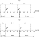
- FIG. 6 is a diagram for illustrating an example of a process in which a processor 130 according to another embodiment of the present disclosure diagnoses a battery.
- the size (Qeod) of the first sub-region, the size (Qp-p) of the second sub-region and the size (Qeoc) of the third sub-region are depicted at an upper side based on an axis (SOC) in FIG. 6
- the size of the SOC of the battery B in the BOL state is depicted in a lower side based on the axis (SOC).
- the processor 130 may calculate the size (Qeod) of the first sub-region, the size (Qp-p) of the second sub-region and the size (Qeoc) of the third sub-region as “14.5%”, “36.5%” and “39%", respectively.
- the processor 130 may calculate the first region change value, the second region change value and the third region change value as "18.69%", “-15.12%” and “5.82%", respectively.
- the processor 130 may calculate the second region change value as "-15.12%” by computing “(36.5%-43%) ⁇ 43% ⁇ 100” using Equation 2.
- the processor 130 may calculate the first region change value as "18.69%” by computing “ ⁇ (14.5%-14%) ⁇ 14% ⁇ 100 ⁇ -(-15.12%)” using Equation 3.
- the processor 130 may calculate the third region change value as "5.82%” by computing “ ⁇ (39%-43%) ⁇ 43% ⁇ 100 ⁇ -(-15.12%)” using Equation 4.
- the processor 130 may diagnose the change of the depth of discharge of the battery B depending on a region of the preset predetermined depth-of-discharge change range to which the first region change value "18.69%" belongs.
- the preset predetermined depth-of-discharge change range may include a first reference change rate range, a second reference change rate range and a third reference change rate range.
- the first reference change rate range may be a region of "less than -10%”
- the second reference change rate range may be a region of "-10% or above and 10% or below”
- the third reference change rate range may be a region "larger than 10%”.
- the processor 130 may determine that the first region change value "18.69%” falls within the third reference change rate range "larger than 10%” and diagnose that the depth of discharge of the battery B is increased.
- the processor 130 may diagnose the change of the active material area of the battery B depending on a region of the preset predetermined active material area change range to which the second region change value "-15.12%" belongs.
- the preset predetermined active material area change range may include a fourth reference change rate range, a fifth reference change rate range and a sixth reference change rate range.
- the fourth reference change rate range may be a range of "less than -10%”
- the fifth reference change rate range may be a range of "-10% or above and 10% or below”
- the sixth reference change rate range may be a range of "larger than 10%”.
- the processor 130 may determine that the second region change value "-15.12%” is included in the fourth reference change rate range "less than -10%", and diagnose that the active material area of the battery B is decreased.
- the processor 130 may diagnose the change of the depth of charge of the battery B depending on a region of the preset predetermined depth-of-charge change range to which the third region change value "5.82%" belongs.
- the preset predetermined depth-of-charge change range may include a seventh reference change rate range, an eighth reference change rate range and a ninth reference change rate range.
- the seventh reference change rate range may be a region of "less than -10%”
- the eighth reference change rate range may be a region of "-10% or above and 10% or below”
- the ninth reference change rate range may be a region of "larger than 10%”.
- the processor 130 may determine that the third region change value "5.82%” is included in the eighth reference change rate range "-10% or above and 10% or below", and diagnose that the depth of charge of the battery B is identical to that of the battery B in the BOL state. In other words, the processor 130 may diagnose that the depth of charge of the battery B is identical to the depth of charge of the battery B in the BOL state. Namely, the processor 130 may diagnose that the depth of charge of the battery B is not changed from the depth of charge of the battery B in the BOL state.
- the processor 130 may determine that the mode of the battery B is a failure mode. That is, since it is diagnosed that the depth of discharge and the active material area are changed, the processor 130 may determine the mode of the battery B as a failure mode.
- the battery diagnostic device may diagnose a change of the internal factors as the battery B degrades, and determine the battery state as a normal mode or a failure mode according to the diagnosis result.
- the battery B is operated according to the determined mode to prevent unexpected problems such as overcharge and overdischarge in advance.
- the processor 130 diagnoses the change of at least one of the active material area, the depth of discharge and the depth of charge of the battery B will be described.
- FIG. 7 is a diagram for illustrating another example of the process in which the processor 130 according to another embodiment of the present disclosure diagnoses a battery.
- the size (Qeod) of the first sub-region, the size (Qp-p) of the second sub-region and the size (Qeoc) of the third sub-region are depicted at an upper side based on an axis (SOC) in FIG. 7
- the size of the SOC of the battery B in the BOL state is depicted in a lower side based on the axis (SOC).
- the processor 130 may calculate the size (Qeod) of the first sub-region, the size (Qp-p) of the second sub-region and the size (Qeoc) of the third sub-region as “14%", “42%” and "34%", respectively.
- the processor 130 may calculate the first region change value, the second region change value and the third region change value as "2.33%”, “-2.33%” and "-18.60%", respectively.
- the processor 130 may calculate the second region change value as "-2.33%” by computing “(42%-43%) ⁇ 43% ⁇ 100” using Equation 2.
- the processor 130 may calculate the first region change value as "2.33%” by computing “ ⁇ (14%-14%) ⁇ 14% ⁇ 100 ⁇ -(-2.33%)” using Equation 3.
- the processor 130 may calculate the third region change value as "-18.60%” by computing “ ⁇ (34%-43%) ⁇ 43% ⁇ 100 ⁇ -(-2.33%)” using Equation 4.
- the processor 130 may diagnose the change of the depth of discharge of the battery B depending on a region of the preset predetermined depth-of-discharge change range to which the first region change value "2.33%” belongs.
- the processor 130 may determine that the first region change value "2.33%” falls within the second reference change rate range "-10% or above and 10% or below” and diagnose that the depth of discharge of the battery B is identical to the depth of discharge of the battery B in the BOL state.
- the processor 130 may diagnose the change of the active material area of the battery B depending on a region of the preset predetermined active material area change range to which the second region change value "-2.33%” belongs.
- the processor 130 may determine that the second region change value "-2.33%” is included in the fifth reference change rate range "-10% or above and 10% or below", and diagnose that the active material area of the battery B is identical to the active material area of the battery B in the BOL state.
- the processor 130 may diagnose the change of the depth of charge of the battery B depending on a region of the preset predetermined depth-of-charge change range to which the third region change value "-18.60%” belongs.
- the processor 130 may determine that the third region change value "-18.60%” is included in the seventh reference change rate range "less than -10%", and diagnose that the depth of charge of the battery B is decreased compared to the depth of charge of the battery B in the BOL state.
- the processor 130 may determine that the mode of the battery B is a failure mode.
- the configuration of the present disclosure it is possible to accurately diagnose the cause of the decrease in the maximum value of the SOC region of the battery B by the changes of the active material area, the depth of discharge and the depth of charge of the battery B.
- the processor 130 may transmit a message indicating the diagnosis result to the external device through a communication terminal (COM).
- COM communication terminal
- the processor 130 may selectively include an application-specific integrated circuit (ASIC), another chipset, a logic circuit, a register, a communication modem, and a data processing device. At least one of the various control logics executable by the processor 130 may be combined, and the combined control logic is written in a computer-readable code system and recorded on a computer-readable recording medium.
- the recording medium has no limitation as long as it can be accessed by the processor 130 included in a computer.
- the recording medium includes at least one selected from the group consisting of a ROM, a RAM, a register, a CD-ROM, a magnetic tape, a hard disk, a floppy disk and an optical data recording device.
- the code system may be modulated into a carrier signal and stored in a communication carrier at a specific time, and may be stored and executed in a distributed manner on computers connected through a network.
- functional programs, code and segments for implementing the combined control logics may be easily inferred by programmers in the technical field to which the present disclosure belongs.
- the notifying unit 140 may receive and output the diagnosis results obtained by the processor 130 to the outside. More specifically, the notifying unit 140 may include at least one of a display unit for displaying the diagnosis result by using at least one of symbols, numbers and codes, and a speaker unit for outputting the diagnosis result with a sound.
- a battery management system may include the battery diagnostic device 100 described above. By doing so, it is possible to diagnose the change of at least one of the active material area, the depth of discharge and the depth of charge of a battery managed by the battery management system.
- FIG. 8 is a flowchart for schematically illustrating a battery diagnostic method according to still another embodiment of the present disclosure.
- a battery diagnosis method according to an embodiment of the present disclosure is described with reference to FIG. 8 .
- the battery diagnostic method may include a SOC estimating step S100, a SOC selecting step S200, a sub-region dividing step S300, a region change value calculating step S400, a diagnosing step S500 and a determining step S600 as operations performed by the battery diagnostic device.
- the SOC estimating step S100 is a step of measuring a current and voltage of a battery B and estimating a SOC of the battery B based on the measured current. Based on the current of the battery B measured by the sensing unit 120, the processor 130 may estimate the SOC of the battery B.
- the sensing unit 120 may measure the voltage and current of the battery B and transmit the measured voltage value and the measured current value to the processor 130.
- the processor 130 may receive the voltage value and the current value from the sensing unit 120 and estimate the SOC of the battery B based on the received current value.
- the SOC selecting step S200 is a step of selecting a plurality of SOCs according to a predetermined condition from SOC-voltage data where the measured voltage and the estimated SOC are mapped with each other. That is, the selecting SOC step S200 is a step of selecting a plurality of SOCs satisfying a predetermined condition among the estimated SOC of the battery B and may be performed by the processor 130.
- the processor 130 may obtain the SOC-voltage data where the voltage value received from the sensing unit 120 and the estimated SOC are mapped with each other, and extract a plurality of inflection points from the obtained SOC-voltage data. After that, the processor 130 may select SOCs of the plurality of inflection points that satisfy the predetermined condition among the plurality of extracted inflection points.
- the processor 130 may select a first inflection point having the smallest SOC size and a second inflection point having the largest SOC size among the plurality of extracted inflection points.
- the processor 130 may select a first SOC of the first inflection point and a second SOC of the second inflection point.
- the sub-region dividing step S300 is a step of dividing a preset SOC region into a plurality of sub-regions based on the size of the plurality of selected SOCs. That is, the sub-region dividing step S300 is a step of dividing the preset SOC region into a plurality of sub-regions based on the selected first SOC and the selected second SOC and may be performed by the processor 130.
- the processor 130 may divide the preset SOC region into a first sub-region, a second sub-region and a third sub-region. For example, the processor 130 may divide the region from the minimum value of the preset SOC region to the first SOC as the first sub-region, divide the region from the first SOC to the second SOC into the second sub-region, and divide the region from the second sub-region to the maximum value of the preset SOC region into the third sub-region.
- the minimum value and the maximum value of the preset SOC region may vary depending on the degradation degree of the battery B.
- the region change value calculating step S400 is a step of calculating a region change value for each of the plurality of sub-regions based on the size of each of the plurality of sub-regions and the size of a preset reference region and may be performed by the processor 130.
- the processor 130 may calculate the size of each of the plurality of divided sub-regions. For example, it is assumed that the minimum value of the preset SOC region is "0%”, the maximum value is "90%", the first SOC is “14%”, and the second SOC is "56%”. The processor 130 may calculate the size of the first sub-region as "14%”, calculate the size of the second sub-region as "42%", and calculate the size of the third sub-region as "34%".
- the processor 130 may calculate the region change value of each sub-region based on the size of the preset reference region and the calculated size of each sub-region. At this time, the processor 130 may calculate the second region change value of the second sub-region by using the Equation 2, calculate the first region change value of the first sub-region by using the Equation 3, and calculate the third region change value of the third sub-region by using the Equation 4.
- the diagnosing step S500 is a step of diagnosing the change of at least one of the active material area, the depth of discharge and the depth of charge of the battery B according to the calculated size of each of the plurality of sub-regions.
- the diagnosing step S500 may be performed by the processor 130.
- the processor 130 may compare the calculated first region change value, the calculated second region change value and the calculated third region change value with the preset range, respectively, and diagnose the change of the depth of discharge, the active material area and the depth of charge of the battery B according to the comparison result.
- the processor 130 may diagnose the change of the depth of discharge of the battery B according to the region where the calculated first region change value belongs to the preset depth-of-discharge change range. In addition, the processor 130 may diagnose the change of the active material area of the battery B according to the region where the calculated second region change value belongs to the preset active material area change range. Also, the processor 130 may diagnose the change of the depth of charge of the battery B according to the region where the calculated third region change value belongs to the preset depth-of-charge change range.
- the determining step S600 is a step of determining the mode of the battery B as a normal mode or a failure mode based on the diagnosis result, and may be performed by the processor 130.
- the processor 130 may determine that the mode of the battery B is a failure mode. Specifically, the processor 130 may determine that the mode of the battery B is a failure mode if it is diagnosed that at least one of the depth of discharge, the active material area and the depth of charge of the battery B is increased or decreased compared to the BOL state.
- the processor 130 may determine that the mode of the battery B is a failure mode.
- the processor 130 determines that the mode of the battery B is a failure mode, thereby preventing unexpected problems that might occur at the battery B in advance.
Landscapes
- Engineering & Computer Science (AREA)
- Physics & Mathematics (AREA)
- General Physics & Mathematics (AREA)
- Manufacturing & Machinery (AREA)
- Chemical & Material Sciences (AREA)
- Chemical Kinetics & Catalysis (AREA)
- Electrochemistry (AREA)
- General Chemical & Material Sciences (AREA)
- Power Engineering (AREA)
- Life Sciences & Earth Sciences (AREA)
- Sustainable Energy (AREA)
- Sustainable Development (AREA)
- Transportation (AREA)
- Mechanical Engineering (AREA)
- Microelectronics & Electronic Packaging (AREA)
- Secondary Cells (AREA)
- Charge And Discharge Circuits For Batteries Or The Like (AREA)
- Tests Of Electric Status Of Batteries (AREA)
Abstract
Description
- The present application claims priority to Korean Patent Application No.
10-2018-0041690 filed on April 10, 2018 - The present disclosure relates to a battery diagnostic device and method, and more particularly, to a battery diagnostic device and method for diagnosing a change of at least one of an active material area, a depth of discharge and a depth of charge of a battery.
- A secondary battery generates electric energy through electrochemical oxidation and reduction reactions and is used in a wide variety of applications. For example, the use area of the secondary battery is gradually expanding to portable devices capable of being carried in a human hand, such as a cellular phone, a laptop computer, a digital camera, a video camera, a tablet computer, or a power tool; various electricity-driven devices such as an electric bicycle, an electric motorcycle, an electric vehicle, a hybrid electric vehicle, an electric boat, or an electric plane; power storage devices used for storing power generated by renewable energy or surplus generated power; power supply devices for stably supplying power to various information communication devices including a server computer and a base station for communication; and the like.
- The secondary battery includes three basic components, namely a negative electrode (anode) containing a substance that is oxidized while discharging electrons during discharge, a positive electrode (cathode) containing a substance that is reduced while accepting electrons during discharge, and an electrolyte that allows ion transfer between the negative electrode and the positive electrode. The battery may be classified as a primary battery that is not reusable after being discharged and a secondary battery that allows repeated charging and discharging since the electrochemical reaction is at least partly reversible.
- Examples of secondary batteries known in the art include lead-acid batteries, nickel-cadmium batteries, nickel-zinc batteries, nickel-iron batteries, silver oxide batteries, nickel metal hydride batteries, zinc-manganese oxide batteries, zinc-bromide batteries, metal-air batteries, lithium secondary batteries, and the like. Among them, the lithium secondary batteries have attracted the greatest commercial interest due to their high energy density, high battery voltage and long life, compared to other secondary batteries.
- Meanwhile, an electronic device employing the secondary battery generally has a function of informing a residual usage amount by using a SOC (State Of Charge) of the secondary battery. The SOC of the secondary battery is usually obtained according to SOC-voltage data on the change pattern of SOC, caused by the change of voltage of the secondary battery. Here, the voltage of the secondary battery may be an open circuit voltage of the secondary battery.
- The SOC-voltage data is not only dependent on the type and capacity of the applied secondary battery but also dependent on the degradation due to use even when the type or capacity of the secondary battery is specified.
- More specifically, the SOC-voltage data depends on the degradation, capacity design and type of active material of each of the positive electrode and the negative electrode of the secondary battery.
- In the conventional technique for diagnosing a secondary battery by using the SOC-voltage data, only the degradation of the secondary battery is diagnosed, and it is impossible to diagnose an active material area, a depth of discharge and a depth of charge of the secondary battery.
- The present disclosure is directed to providing a battery diagnostic device and method for diagnosing a change of at least one of an active material area, a depth of discharge and a depth of charge of a battery based on a change of regional size of a preset SOC region calculated according to the state of the battery.
- These and other objects and advantages of the present disclosure may be understood from the following detailed description and will become more fully apparent from the exemplary embodiments of the present disclosure. Also, it will be easily understood that the objects and advantages of the present disclosure may be realized by the means shown in the appended claims and combinations thereof.
- In one aspect of the present disclosure, there is provided a battery diagnostic device, comprising: a sensing unit configured to measure a current and voltage of a battery; and a processor configured to estimate a SOC (State Of Charge) of the battery based on the current measured by the sensing unit, select a plurality of SOCs according to a predetermined condition from SOC-voltage data where the voltage measured by the sensing unit and the estimated SOC are mapped with each other, divide a preset SOC region into a plurality of sub-regions based on a size of the plurality of selected SOCs, calculate a size of each of the plurality of sub-regions based on the size of each of the plurality of divided sub-regions and a size of a preset reference region, diagnose a change of at least one of an active material area, a depth of discharge and a depth of charge of the battery according to a change value of the calculated size of each of the plurality of sub-regions, and determine whether a mode of the battery is a normal mode or a failure mode based on the diagnosis result.
- The processor may be configured to obtain a SOC-voltage curve from the SOC-voltage data, extract a plurality of inflection points in the obtained SOC-voltage curve, and select SOCs at some inflection points selected according to the predetermined condition from the plurality of extracted inflection points.
- The processor may be configured to select a SOC having a smallest size among the plurality of selected SOCs as a first SOC, select a SOC having a largest size as a second SOC, and divide the preset SOC region into a first sub-region, a second sub-region and a third sub-region based on points corresponding to the first SOC and the second SOC in the preset SOC region.
- The processor may be configured to calculate a second region change value based on a difference between a size of the second sub-region and a size of a second reference region of the preset reference region, and diagnose the change of the active material area of the battery according to the calculated second region change value.
- The processor may be configured to diagnose the change of the active material area of the battery according to the second region change value calculated according to an equation below:

- The processor may be configured to diagnose the change of the active material area of the battery according to a region corresponding to the calculated second region change value in a preset predetermined active material area change range, and determine that the mode of the battery is a failure mode when it is diagnosed that the active material area is changed.
- The processor may be configured to calculate a first region change value based on a size of the first sub-region, a size of a first reference region of the preset reference region and the calculated second region change value, and diagnose the change of the depth of discharge of the battery according to the calculated first region change value.
- The processor may be configured to diagnose the change of the depth of discharge of the battery according to the first region change value calculated according to an equation below:

- The processor may be configured to diagnose the change of the depth of discharge of the battery according to a region corresponding to the calculated first region change value in a preset predetermined depth-of-discharge change range, and determine that the mode of the battery is a failure mode when it is diagnosed that the depth of discharge is changed.
- The processor may be configured to calculate a third region change value based on a size of the third sub-region, a size of a third reference region of the preset reference region and the calculated second region change value, and diagnose the change of the depth of charge of the battery according to the calculated third region change value.
- The processor may be configured to diagnose the change of the depth of charge of the battery according to the third region change value calculated according to an equation below:

- The processor may be configured to diagnose the change of the depth of charge of the battery according to a region corresponding to the calculated third region change value in a preset predetermined depth-of-charge change range, and determine that the mode of the battery is a failure mode when it is diagnosed that the depth of charge is changed.
- A battery management system according to another embodiment of the present disclosure may comprise the battery diagnostic device according to an embodiment of the present disclosure.
- A battery pack according to another embodiment of the present disclosure may comprise the battery diagnostic device according to an embodiment of the present disclosure.
- A battery diagnostic method according to another embodiment of the present disclosure may comprise: a SOC estimating step of measuring a current and voltage of a battery and estimating a SOC of the battery based on the measured current; a SOC selecting step of selecting a plurality of SOCs according to a predetermined condition from SOC-voltage data where the measured voltage and the estimated SOC are mapped with each other; a sub-region dividing step of dividing a preset SOC region into a plurality of sub-regions based on a size of the plurality of selected SOCs; a region change value calculating step of calculating a region change value of each of the plurality of sub-regions based on a size of each of the plurality of divided sub-regions and a size of a preset reference region; a diagnosing step of diagnosing a change of at least one of an active material area, a depth of discharge and a depth of charge of the battery according to the calculated size of each of the plurality of sub-regions; and a mode determining step of determining whether a mode of the battery is a failure mode based on the diagnosis result of the diagnosing step.
- According to the present disclosure, a change of a SOC region may be determined based on SOC and voltage of a battery, and a change of at least one of an active material area, a depth of discharge and a depth of charge of the battery may be diagnosed through the determined change of region.
- In addition, according to the present disclosure, since the change of at least one of the active material area, the depth of discharge and the depth of charge of the battery is diagnosed, it is possible to determine whether the mode of the battery is included in a normal mode or a failure mode.
- That is, according to the present disclosure, the cause of degeneration of each battery may be specifically diagnosed, and the mode of the battery may be classified into a normal mode or a failure mode.
- The accompanying drawings illustrate a preferred embodiment of the present disclosure and together with the foregoing disclosure, serve to provide further understanding of the technical features of the present disclosure, and thus, the present disclosure is not construed as being limited to the drawing.
-
FIG. 1 is a diagram showing a battery diagnostic device according to an embodiment of the present disclosure. -
FIG. 2 is a graph showing a voltage of a battery according to a SOC of the battery. -
FIGS. 3 and4 are voltage differential graphs of the battery according to the SOC of the battery before and after smoothing. -
FIG. 5 is a diagram for illustrating a process in which a processor according to the present disclosure selects a first SOC and a second SOC and calculates a size of a first sub-region, a size of a second sub-region and a size of a third sub-region. -
FIG. 6 is a diagram for illustrating an example of a process in which a processor according to another embodiment of the present disclosure diagnoses a battery. -
FIG. 7 is a diagram for illustrating another example of the process in which a processor according to another embodiment of the present disclosure diagnoses a battery. -
FIG. 8 is a flowchart for schematically illustrating a battery diagnostic method according to still another embodiment of the present disclosure. - Hereinafter, preferred embodiments of the present disclosure will be described in detail with reference to the accompanying drawings. Prior to the description, it should be understood that the terms used in the specification and the appended claims should not be construed as limited to general and dictionary meanings, but interpreted based on the meanings and concepts corresponding to technical aspects of the present disclosure on the basis of the principle that the inventor is allowed to define terms appropriately for the best explanation.
- Therefore, the description proposed herein is just a preferable example for the purpose of illustrations only, not intended to limit the scope of the disclosure, so it should be understood that other equivalents and modifications could be made thereto without departing from the scope of the disclosure.
- Additionally, in describing the present disclosure, when it is deemed that a detailed description of relevant known elements or functions renders the key subject matter of the present disclosure ambiguous, the detailed description is omitted herein.
- The terms including the ordinal number such as "first", "second" and the like, may be used to distinguish one element from another among various elements, but not intended to limit the elements by the terms.
- Throughout the specification, when a portion is referred to as "comprising" or "including" any element, it means that the portion may include other elements further, without excluding other elements, unless specifically stated otherwise. Furthermore, the term <processor> described in the specification refers to a unit that processes at least one function or operation, and may be implemented by hardware, software, or a combination of hardware and software.
- In addition, throughout the specification, when a portion is referred to as being "connected" to another portion, it is not limited to the case that they are "directly connected", but it also includes the case where they are "indirectly connected" with another element being interposed between them.
-
FIG. 1 is a diagram showing a battery diagnostic device according to an embodiment of the present disclosure,FIG. 2 is a graph showing a voltage of a battery according to a SOC of the battery,FIGS. 3 and4 are voltage differential graphs of the battery according to the SOC of the battery before and after smoothing, andFIG. 5 is a diagram for illustrating a process in which a processor according to the present disclosure selects a first SOC and a second SOC and calculates a size of a first sub-region, a size of a second sub-region and a size of a third sub-region. - First, referring to
FIG. 1 , a batterydiagnostic device 100 according to an embodiment of the present disclosure may be included in a battery pack 1 that has a battery B and may be connected to the battery B to diagnose a change of at least one of an active material area, a depth of discharge and a depth of charge of the battery B. For example, the active material area, the depth of discharge and the depth of charge of the battery B may be an active material area, a depth of discharge and a depth of charge of an electrode of the battery. - Meanwhile, the battery
diagnostic device 100 according to an embodiment of the present disclosure may be included in a battery management system (BMS) provided in the battery pack 1. - The battery
diagnostic device 100 may include asensing unit 110, amemory unit 120, aprocessor 130 and a notifyingunit 140. - The battery B is a minimum unit cell whose change of at least one of an active material area, a depth of discharge and a depth of charge is diagnosed, and includes a plurality of unit cells electrically connected in series and/or in parallel. Of course, the case where the battery pack B includes only one unit cell also falls into the scope of the present disclosure.
- The unit cell is not limited to a particular type and includes any cell type that can be recharged repeatedly. For example, the unit cell may be a pouch-type lithium polymer battery.
- The battery B may be electrically coupled to various types of external devices through an external terminal. The external device may be, for example, an electric vehicle, a hybrid electric vehicle, a flying object such as a drone, a large-capacity energy storage system (ESS) included in an electrical grid, or a mobile device. In this case, the battery B may include some or all unit cells included in a modularized battery pack mounted in the external device.
- The external terminal of the battery B may be selectively coupled to a charging device. The charging device may be selectively coupled to the battery B by the control of the external device to which the battery pack B is mounted.
- The
sensing unit 110 is operably coupled to theprocessor 130. That is, thesensing unit 110 may be connected to theprocessor 130 to transmit an electrical signal to theprocessor 130 or receive an electrical signal from theprocessor 130. - The
sensing unit 110 may repeatedly measure a voltage applied between a positive electrode and a negative electrode of the battery B and a current flowing into or out of the battery B at predetermined intervals, and provide a measurement signal indicating the measured voltage and current to theprocessor 130. - The
sensing unit 110 includes a current sensor configured to measure the current of the battery B. Also, thesensing unit 110 may further include a voltage sensor configured to measure the voltage of the battery B. Though not shown inFIG. 1 , the current sensor may be connected to both ends of a sense resistor connected to the battery B through a circuit. That is, the current sensor may measure a potential difference between both ends of the sense resistor and measure the current of the battery B based on the measured potential difference and the resistance value of the sense resistor. - When the
processor 130 receives the measurement signal from thesensing unit 110, theprocessor 130 may determine a digital value of each of voltage and current of the battery through signal processing, and store the digital value in thememory unit 120. - The
memory unit 120 is a semiconductor memory device that records, erases and updates data generated by theprocessor 130, and stores a plurality of program codes prepared for diagnosing a change of at least one of an active material area, a depth of discharge and a depth of charge of the battery B. In addition, thememory unit 120 may store preset values of various predetermined parameters used in implementing the present disclosure. - The
memory unit 120 may is not particularly limited as long as it is a semiconductor memory element known in the art as being capable of recording, erasing and updating data. For example, thememory unit 120 may be DRAM, SDRAM, a flash memory, ROM, EEPROM, a register, and the like. In addition, thememory unit 120 may further include a storage medium that stores program codes defining the control logics of theprocessor 130. The storage medium includes a non-volatile storage element such as a flash memory or a hard disk. Thememory unit 120 may be physically separate from theprocessor 130 or may be integrated with theprocessor 130. - The
processor 130 may control the current of the battery B so that the current of a preset charging current value is inputted to the battery B to charge the battery B, and estimate a SOC (State Of Charge) of the battery B based on the current input to the battery B. - At this time, the preset charging current value may be calculated using Equation 1 below.

- Here, Ic may be a preset charging current value, α may be a constant of 1 or less, and Cn may be a rated current of the battery.
- Accordingly, the
processor 130 may estimate the SOC of the battery B which is charged by receiving the current having a charging current value equal to or less than the rated current. - Here, the SOC of the battery B may be a ratio of a charged capacity to the total capacity of the battery B.
- The
processor 130 may estimate the SOC of the battery B by using a current integration method that integrates current values of the current input to the battery B. That is, theprocessor 130 may estimate the SOC of the battery based on the current measured by thesensing unit 110. - Even though it has been described that the
processor 130 estimates the SOC of the battery B by using the current integration method, the estimation method is not limited thereto as long as the SOC of the battery B to which the current of a preset charging current value is input can be estimated. - Meanwhile, the
processor 130 may generate SOC-voltage data of the battery B by mapping the voltage of the battery B with the estimated SOC of the battery B. That is, theprocessor 130 may generate the SOC-voltage data of the battery B by mapping the voltage measured by thesensing unit 120 and the estimated SOC of the battery B with each other. - Here, the voltage of the battery B may be an open circuit voltage of the battery B.
- The SOC-voltage data of the battery B may be expressed using a voltage curve of the battery B according to the SOC of the battery B, as shown in
FIG. 2 . - At this time, the
memory unit 120 may store the SOC-voltage data of the battery B in at least one form of an approximation function that approximates the SOC-voltage data of the battery B to the battery curve of the battery B according to the SOC of the battery B and a lookup table where the voltage of the battery B is mapped with each SOC of the battery B. - The
processor 130 may select a plurality of SOCs from the SOC-voltage data according to a predetermined condition. Specifically, theprocessor 130 may select a plurality of inflection points in the SOC-voltage data and select a SOC corresponding to each of the plurality of selected inflection points. - For example, in the embodiment of
FIG. 2 , theprocessor 130 may select a plurality of inflection points in the SOC-voltage curve that is expressed based on the SOC-voltage data of the battery B. Specifically, referring toFIG. 4 , theprocessor 130 may select points a1 to a7 as the inflection points. - For example, the
processor 130 may detect the SOC and the voltage of the battery B at a point where the change of the voltage of the battery B increases and then decreases according to a minute change of the SOC based on the SOC-voltage data as the inflection point. Also, theprocessor 130 may detect the SOC and the voltage of the battery B at a point where the change of the voltage of the battery B decreases and then increases according to the minute change of the SOC based on the SOC-voltage data as the inflection point. That is, theprocessor 130 may detect the SOC where a second-order derivative coefficient of an approximation function corresponding to the SOC-voltage data of the battery B is "0" and the voltage of the battery B corresponding to the SOC as the inflection point. - To this end, the
processor 130 may calculate a first-order derivative by differentiating the approximation function corresponding to the SOC-voltage data of the battery B, as shown inFIG. 3 . - After that, the
processor 130 may remove noise components by smoothing the first-order derivative of the approximation function corresponding to the SOC-voltage data of the battery B, as shown inFIG. 4 . - At this time, the
processor 130 may smooth the first-order derivative of the approximation function corresponding to the SOC-voltage data of the battery B by using a noise filter. - In this way, the
processor 130 may prevent false detection of the inflection point caused by noise components, thereby improving the accuracy of inflection point detection. - Subsequently, the
processor 130 may calculate a second-order derivative by differentiating the first-order derivative of the smoothed approximation function, and detect the SOC where a function value of the calculated second-order derivative is "0" and the voltage of the battery B corresponding to the SOC as the inflection point. - For example, as shown in
FIG. 4 , theprocessor 130 may detect seven inflection points a1 to a7. Here, the SOC (X-axis value) corresponding to the seven inflection points a1 to a7 may be "7.2%", "13.6%", "19.1%", "21.2%", "35.3%", "56.8%" and "60.0%", respectively. - The
processor 130 may divide the preset SOC region into a plurality of sub-regions based on the size of the plurality of selected SOCs. Specifically, theprocessor 130 may select a first SOC having the smallest size and a second SOC having the largest size among the plurality of selected SOCs. Theprocessor 130 may divide the preset SOC region into the plurality of sub-regions based on points corresponding to the first SOC and the second SOC selected in the preset SOC region. - For example, the
processor 130 may divide a region between the minimum value and the first SOC in the preset SOC region into a first sub-region, divide a region between the first SOC and the second SOC into a second sub-region, and divide a region between the second SOC and the maximum value into a third sub-region. - Here, the range of the preset SOC region may be limited a region from the minimum value to maximum value of the SOC estimated by the
processor 130. For example, as shown inFIG. 2 , the range of the preset SOC region may be limited to "0%" to "100%". Accordingly, the minimum value of the SOC region may be "0%", and the maximum value of the SOC region may be "100%". - For example, as shown in
FIG. 5 , theprocessor 130 may select the smallest SOC "7.2%" among the SOCs "7.2%", "13.6%", "19.1%", "21.2%", "35.3%", "56.8%" and "60.0%" corresponding to the detected seven inflection points a1 to a7 as the first SOC (Q1) and select the largest SOC "60.0%" as the second SOC (Q2). - After that, the
processor 130 may divide the region of "0%" to "7.2%" into the first sub-region, divide the region of "7.2%" to "60.0%" into the second sub-region, and divide the region of "60.0%" to "100%" into the third sub-region. In addition, theprocessor 130 may calculate a difference value "7.2%" between the minimum value "0%" of the SOC region and the first SOC (Q1) "7.2%" as the size (Qeod) of the first sub-region. Also, theprocessor 130 may calculate a difference value 52.8% between the first SOC (Q1) "7.2%" and the second SOC (Q2) "60.0%" as the size (Qp-p) of the second sub-region. In addition, theprocessor 130 may calculate a difference value 40.0% between the second SOC (Q2) "60.0%" and the maximum value "100%" of the SOC region as the size (Qeoc) of the third sub-region. - The
processor 130 may calculate a region change rate for each sub-region based on the sizes of the first to third sub-regions and the size of a preset reference region. - Specifically, the
processor 130 may calculate a second region change value by using the size of the second sub-region and the size of a second reference region. Also, theprocessor 130 may calculate a first region change value by using the size of the first sub-region, the size of a first reference region and the second region change value. In addition, theprocessor 130 may calculate a third region change value using the size of the third sub-region, the size of a third reference region and the second region change value. - The
processor 130 may calculate the second region change value using Equation 2 below.
- Here, Qvp-p is the second region change value, Qrp-p is the size of the second reference region, and Qp-p is the size of the second sub-region.
- For example, according to Equation 2, the
processor 130 may calculate "-15.12%" as the second region change value (Qvp-p). - In addition, the
processor 130 may calculate the first region change value by using the size of the first sub-region, the size of the first reference region, and the second region change value. Specifically, theprocessor 130 may calculate the first region change value using Equation 3 below.
- Here, Qveod is the first region change value, Qreod is the size of the first reference region, Qeod is the size of the first sub-region, and Qvp-p is the second region change value.
- For example, it is assumed that the size (Qreod) of the first reference region is "14%", the size (Qeod) of the first sub-region is "14.5%", and the second region change value (Qvp-p) is "-15.12%". First, the
processor 130 may calculate a ratio of the difference between the size of the first sub-region and the size of the first reference region to the size of the first reference region by using Equation 3. That is, theprocessor 130 may calculate "3.57%" from the result of calculation "(14.5%-14%)/14%×100". In addition, theprocessor 130 may calculate the first region change value based on the difference between the calculated result and the second region change value. Theprocessor 130 may calculate the first region change value (Qveod) "18.69%" from the result of calculation "3.57%-(-15.12%)". - In addition, the
processor 130 may calculate the third region change value by using the size of the third reference region, the size of the third sub-region, and the second region change value. Specifically, the processor 103 may calculate the third region changevalue using Equation 4 below.
- Here, Qveoc is the third region change value, Qreoc is the size of the third reference region, Qeoc is the size of the third sub-region, and Qvp-p is the second region change value.
- For example, it is assumed that the size (Qreoc) of the third reference region is "43%", the size (Qeoc) of the third sub-region is "39%", and the second region change value (Qvp-p) is "-15.12%". First, the
processor 130 may calculate a ratio of the difference between the size of the third sub-region and the size of the third reference region to the size of the third reference region by usingEquation 4. That is, theprocessor 130 may calculate "-9.3%" from the result of calculation "(39%-43%)/43%×100". In addition, theprocessor 130 may calculate the third region change value based on the difference between the calculated result and the second region change value. Theprocessor 130 may calculate the third region change value "5.82%" from the result of calculation "-9.3%-(-15.12%)". - After that, the
processor 130 may diagnose the change of at least of the active material area, the depth of discharge and the depth of charge of the battery B according to the calculated change value of each of the plurality of sub-regions. - The
processor 130 may diagnose the change of the depth of discharge of the battery B according to a region corresponding to the calculated first region change value in a preset predetermined depth-of-discharge change range. Also, theprocessor 130 may diagnose the change of the active material area of the battery B according to a region corresponding to the calculated second region change value in a preset predetermined active material area change range. In addition, theprocessor 130 may diagnose the change of the depth of charge of the battery B according to a region corresponding to the calculated third region change value in a preset predetermined depth-of-charge change range. - For example, all of the preset predetermined depth-of-discharge change range, the active material area change range and the depth-of-charge change range may be classified into ranges of "less than -10%", "-10% or above and 10% or below", "larger than 10%". In addition, in all of the preset predetermined depth-of-discharge change range, the active material area change range and the depth-of-charge change range, the region "less than - 10%" may be diagnosed as a region that decreased below a BOL (Beginning Of Life) state, the region "-10% or above and 10% or below" may be diagnosed as a region that is identical to the BOL state, and the region "larger 10%" may be diagnosed as a region that increases over the BOL state.
- For example, it is assumed as in the former embodiment that the first region change value is calculated as "18.69%", the second region change value is calculated as "-15.12%", and the third region change value is calculated as "5.82%". In this case, since the first region change value "18.69%" falls within the range "larger than 10%" in the preset predetermined depth-of-discharge change range, the
processor 130 may diagnose that the depth of discharge of the battery B increases. Also, since the second region change value "-15.12%" belongs to the range "less than -10%" in the preset predetermined active material area change range, theprocessor 130 may diagnose that the active material area of the battery B decreases. In addition, since the third region change value "5.82%" belongs to the range "-10% or above and 10% or below" in the preset predetermined depth-of-charge change range, theprocessor 130 may diagnose that the depth of charge of the battery B is identical to the depth of charge of a battery B in the BOL state. - The
processor 130 may be configured to diagnose the change of at least one of the active material area, the depth of discharge and the depth of charge of the battery B, and then determine whether the mode of the battery B is a normal mode or a failure mode based on the diagnosis result. - If it is determined that any one of the active material area, the depth of discharge and the depth of charge of the battery B is changed compared to the BOL state, the
processor 130 may determine that the mode of the battery is a failure mode. Specifically, theprocessor 130 may determine that the mode of the battery is a failure mode if any one of the active material area, the depth of discharge and the depth of charge of the battery B does not belong to the region "-10% or above and 10% or below". - For example, it is assumed as in the former embodiment that the first region change value is calculated as "18.69%", the second region change value is calculated as "-15.12%", and the third region change value is calculated as "5.82%". In this case, the
processor 130 may diagnose that the depth of discharge of the battery B is increased, the change of the active material area is decreased, and the depth of charge is identical to the BOL state. In addition, since the change of the active material area of the battery B is decreased and the depth of discharge is increased, theprocessor 130 may determine that the mode of the battery is a failure mode. Namely, theprocessor 130 may determine that the mode of the battery B is a failure mode if it is determined that any one of the change of the active material area, the change of the depth of discharge and the change of the depth of charge associated with degradation of the battery B is increased or decreased compared to the BOL state. - The
processor 130 may determine the mode of the battery B and then set the mode of the battery B as the determined mode. For example, if the mode of the battery B is determined as a failure mode, theprocessor 130 may set the mode of the battery B to the failure mode. Conversely, if the mode of the battery B is determined as a normal mode, theprocessor 130 may set the mode of the battery B to the normal mode. - Thus, the battery diagnostic device according to an embodiment of the present disclosure may correctly diagnose the cause of battery degeneration and determine the mode of the battery as any one of a normal mode and a failure mode depending on the cause of degeneration. In addition, if it is determined that any one of the change of the active material area, the change of the depth of discharge and the change of the depth of charge is increased or decreased compared to the BOL state, the battery diagnostic device may determine that the battery mode is a failure mode and prevent an unexpected problem that may be caused due to the degradation of the battery such as overdischarge and overcharge.
- Hereinafter, an example of a process that the
processor 130 diagnoses the change of at least one of the active material area, the depth of discharge and the depth of charge of the battery B will be described in more detail with reference toFIGS. 6 and 7 . -
FIG. 6 is a diagram for illustrating an example of a process in which aprocessor 130 according to another embodiment of the present disclosure diagnoses a battery. Here, it should be noted that the size (Qeod) of the first sub-region, the size (Qp-p) of the second sub-region and the size (Qeoc) of the third sub-region are depicted at an upper side based on an axis (SOC) inFIG. 6 , and the size of the SOC of the battery B in the BOL state is depicted in a lower side based on the axis (SOC). - As shown in
FIG. 6 , it is assumed that the minimum value of the SOC region is "0%" and the maximum value is decreased to "90%" according to the SOC-voltage data due to the degradation of the battery B. In addition, if it is assumed that the first SOC (Q1) and the second SOC (Q2) of the battery B are respectively "14.5%" and "51%", theprocessor 130 may calculate the size (Qeod) of the first sub-region, the size (Qp-p) of the second sub-region and the size (Qeoc) of the third sub-region as "14.5%", "36.5%" and "39%", respectively. At this time, if the size (Qeod) of the first sub-region, the size (Qp-p) of the second sub-region and the size (Qeoc) of the third sub-region are respectively "14%", "43%" and "43%", theprocessor 130 may calculate the first region change value, the second region change value and the third region change value as "18.69%", "-15.12%" and "5.82%", respectively. - For example, the
processor 130 may calculate the second region change value as "-15.12%" by computing "(36.5%-43%)÷43%×100" using Equation 2. In addition, theprocessor 130 may calculate the first region change value as "18.69%" by computing "{(14.5%-14%)÷14%×100}-(-15.12%)" using Equation 3. In addition, theprocessor 130 may calculate the third region change value as "5.82%" by computing "{(39%-43%)÷43%×100}-(-15.12%)" usingEquation 4. - The
processor 130 may diagnose the change of the depth of discharge of the battery B depending on a region of the preset predetermined depth-of-discharge change range to which the first region change value "18.69%" belongs. The preset predetermined depth-of-discharge change range may include a first reference change rate range, a second reference change rate range and a third reference change rate range. Here, the first reference change rate range may be a region of "less than -10%", the second reference change rate range may be a region of "-10% or above and 10% or below", and the third reference change rate range may be a region "larger than 10%". - The
processor 130 may determine that the first region change value "18.69%" falls within the third reference change rate range "larger than 10%" and diagnose that the depth of discharge of the battery B is increased. - The
processor 130 may diagnose the change of the active material area of the battery B depending on a region of the preset predetermined active material area change range to which the second region change value "-15.12%" belongs. The preset predetermined active material area change range may include a fourth reference change rate range, a fifth reference change rate range and a sixth reference change rate range. Here, the fourth reference change rate range may be a range of "less than -10%", the fifth reference change rate range may be a range of "-10% or above and 10% or below", and the sixth reference change rate range may be a range of "larger than 10%". - The
processor 130 may determine that the second region change value "-15.12%" is included in the fourth reference change rate range "less than -10%", and diagnose that the active material area of the battery B is decreased. - The
processor 130 may diagnose the change of the depth of charge of the battery B depending on a region of the preset predetermined depth-of-charge change range to which the third region change value "5.82%" belongs. The preset predetermined depth-of-charge change range may include a seventh reference change rate range, an eighth reference change rate range and a ninth reference change rate range. Here, the seventh reference change rate range may be a region of "less than -10%", the eighth reference change rate range may be a region of "-10% or above and 10% or below", and the ninth reference change rate range may be a region of "larger than 10%". - The
processor 130 may determine that the third region change value "5.82%" is included in the eighth reference change rate range "-10% or above and 10% or below", and diagnose that the depth of charge of the battery B is identical to that of the battery B in the BOL state. In other words, theprocessor 130 may diagnose that the depth of charge of the battery B is identical to the depth of charge of the battery B in the BOL state. Namely, theprocessor 130 may diagnose that the depth of charge of the battery B is not changed from the depth of charge of the battery B in the BOL state. - Even though the
processor 130 diagnoses that the depth of charge of the battery B is not changed from the depth of charge in the BOL state, since it is diagnosed that the depth of discharge is increased and the active material area is decreased, theprocessor 130 may determine that the mode of the battery B is a failure mode. That is, since it is diagnosed that the depth of discharge and the active material area are changed, theprocessor 130 may determine the mode of the battery B as a failure mode. - In other words, the battery diagnostic device according to an embodiment of the present disclosure may diagnose a change of the internal factors as the battery B degrades, and determine the battery state as a normal mode or a failure mode according to the diagnosis result. Thus, the battery B is operated according to the determined mode to prevent unexpected problems such as overcharge and overdischarge in advance.
- Hereinafter, another example of the process that the
processor 130 diagnoses the change of at least one of the active material area, the depth of discharge and the depth of charge of the battery B will be described. -
FIG. 7 is a diagram for illustrating another example of the process in which theprocessor 130 according to another embodiment of the present disclosure diagnoses a battery. Here, it should be noted that the size (Qeod) of the first sub-region, the size (Qp-p) of the second sub-region and the size (Qeoc) of the third sub-region are depicted at an upper side based on an axis (SOC) inFIG. 7 , and the size of the SOC of the battery B in the BOL state is depicted in a lower side based on the axis (SOC). - As shown in
FIG. 7 , it is assumed that the minimum value of the SOC region is "0%" and the maximum value is decreased to "90%" according to the measured SOC-voltage data of the battery B, and the first SOC (Q1) and the second SOC (Q2) of the battery B are respectively selected as "14%" and "56%". Theprocessor 130 may calculate the size (Qeod) of the first sub-region, the size (Qp-p) of the second sub-region and the size (Qeoc) of the third sub-region as "14%", "42%" and "34%", respectively. - If the size (Qeod) of the first sub-region, the size (Qp-p) of the second sub-region and the size (Qeoc) of the third sub-region are "14%", "42%" and "34%", respectively, the
processor 130 may calculate the first region change value, the second region change value and the third region change value as "2.33%", "-2.33%" and "-18.60%", respectively. - For example, the
processor 130 may calculate the second region change value as "-2.33%" by computing "(42%-43%)÷43%×100" using Equation 2. In addition, theprocessor 130 may calculate the first region change value as "2.33%" by computing "{(14%-14%)÷14%×100}-(-2.33%)" using Equation 3. In addition, theprocessor 130 may calculate the third region change value as "-18.60%" by computing "{(34%-43%)÷43%×100}-(-2.33%)" usingEquation 4. - The
processor 130 may diagnose the change of the depth of discharge of the battery B depending on a region of the preset predetermined depth-of-discharge change range to which the first region change value "2.33%" belongs. Theprocessor 130 may determine that the first region change value "2.33%" falls within the second reference change rate range "-10% or above and 10% or below" and diagnose that the depth of discharge of the battery B is identical to the depth of discharge of the battery B in the BOL state. - The
processor 130 may diagnose the change of the active material area of the battery B depending on a region of the preset predetermined active material area change range to which the second region change value "-2.33%" belongs. Theprocessor 130 may determine that the second region change value "-2.33%" is included in the fifth reference change rate range "-10% or above and 10% or below", and diagnose that the active material area of the battery B is identical to the active material area of the battery B in the BOL state. - The
processor 130 may diagnose the change of the depth of charge of the battery B depending on a region of the preset predetermined depth-of-charge change range to which the third region change value "-18.60%" belongs. Theprocessor 130 may determine that the third region change value "-18.60%" is included in the seventh reference change rate range "less than -10%", and diagnose that the depth of charge of the battery B is decreased compared to the depth of charge of the battery B in the BOL state. - Even though the
processor 130 diagnoses that the depth of discharge and the active material area of battery B are not changed, since it is diagnosed that the depth of charge is decreased, theprocessor 130 may determine that the mode of the battery B is a failure mode. - According to the configuration of the present disclosure, it is possible to accurately diagnose the cause of the decrease in the maximum value of the SOC region of the battery B by the changes of the active material area, the depth of discharge and the depth of charge of the battery B.
- The
processor 130 may transmit a message indicating the diagnosis result to the external device through a communication terminal (COM). - The
processor 130 may selectively include an application-specific integrated circuit (ASIC), another chipset, a logic circuit, a register, a communication modem, and a data processing device. At least one of the various control logics executable by theprocessor 130 may be combined, and the combined control logic is written in a computer-readable code system and recorded on a computer-readable recording medium. The recording medium has no limitation as long as it can be accessed by theprocessor 130 included in a computer. As one example, the recording medium includes at least one selected from the group consisting of a ROM, a RAM, a register, a CD-ROM, a magnetic tape, a hard disk, a floppy disk and an optical data recording device. In addition, the code system may be modulated into a carrier signal and stored in a communication carrier at a specific time, and may be stored and executed in a distributed manner on computers connected through a network. Moreover, functional programs, code and segments for implementing the combined control logics may be easily inferred by programmers in the technical field to which the present disclosure belongs. - The notifying
unit 140 may receive and output the diagnosis results obtained by theprocessor 130 to the outside. More specifically, the notifyingunit 140 may include at least one of a display unit for displaying the diagnosis result by using at least one of symbols, numbers and codes, and a speaker unit for outputting the diagnosis result with a sound. - Meanwhile, a battery management system according to the present disclosure may include the battery
diagnostic device 100 described above. By doing so, it is possible to diagnose the change of at least one of the active material area, the depth of discharge and the depth of charge of a battery managed by the battery management system. -
FIG. 8 is a flowchart for schematically illustrating a battery diagnostic method according to still another embodiment of the present disclosure. Hereinafter, a battery diagnosis method according to an embodiment of the present disclosure is described with reference toFIG. 8 . - The battery diagnostic method may include a SOC estimating step S100, a SOC selecting step S200, a sub-region dividing step S300, a region change value calculating step S400, a diagnosing step S500 and a determining step S600 as operations performed by the battery diagnostic device.
- The SOC estimating step S100 is a step of measuring a current and voltage of a battery B and estimating a SOC of the battery B based on the measured current. Based on the current of the battery B measured by the
sensing unit 120, theprocessor 130 may estimate the SOC of the battery B. - First, the
sensing unit 120 may measure the voltage and current of the battery B and transmit the measured voltage value and the measured current value to theprocessor 130. Theprocessor 130 may receive the voltage value and the current value from thesensing unit 120 and estimate the SOC of the battery B based on the received current value. - The SOC selecting step S200 is a step of selecting a plurality of SOCs according to a predetermined condition from SOC-voltage data where the measured voltage and the estimated SOC are mapped with each other. That is, the selecting SOC step S200 is a step of selecting a plurality of SOCs satisfying a predetermined condition among the estimated SOC of the battery B and may be performed by the
processor 130. - The
processor 130 may obtain the SOC-voltage data where the voltage value received from thesensing unit 120 and the estimated SOC are mapped with each other, and extract a plurality of inflection points from the obtained SOC-voltage data. After that, theprocessor 130 may select SOCs of the plurality of inflection points that satisfy the predetermined condition among the plurality of extracted inflection points. - For example, the
processor 130 may select a first inflection point having the smallest SOC size and a second inflection point having the largest SOC size among the plurality of extracted inflection points. In addition, theprocessor 130 may select a first SOC of the first inflection point and a second SOC of the second inflection point. - The sub-region dividing step S300 is a step of dividing a preset SOC region into a plurality of sub-regions based on the size of the plurality of selected SOCs. That is, the sub-region dividing step S300 is a step of dividing the preset SOC region into a plurality of sub-regions based on the selected first SOC and the selected second SOC and may be performed by the
processor 130. - The
processor 130 may divide the preset SOC region into a first sub-region, a second sub-region and a third sub-region. For example, theprocessor 130 may divide the region from the minimum value of the preset SOC region to the first SOC as the first sub-region, divide the region from the first SOC to the second SOC into the second sub-region, and divide the region from the second sub-region to the maximum value of the preset SOC region into the third sub-region. - At this time, the minimum value and the maximum value of the preset SOC region may vary depending on the degradation degree of the battery B.
- The region change value calculating step S400 is a step of calculating a region change value for each of the plurality of sub-regions based on the size of each of the plurality of sub-regions and the size of a preset reference region and may be performed by the
processor 130. - The
processor 130 may calculate the size of each of the plurality of divided sub-regions. For example, it is assumed that the minimum value of the preset SOC region is "0%", the maximum value is "90%", the first SOC is "14%", and the second SOC is "56%". Theprocessor 130 may calculate the size of the first sub-region as "14%", calculate the size of the second sub-region as "42%", and calculate the size of the third sub-region as "34%". - After that, the
processor 130 may calculate the region change value of each sub-region based on the size of the preset reference region and the calculated size of each sub-region. At this time, theprocessor 130 may calculate the second region change value of the second sub-region by using the Equation 2, calculate the first region change value of the first sub-region by using the Equation 3, and calculate the third region change value of the third sub-region by using theEquation 4. - The diagnosing step S500 is a step of diagnosing the change of at least one of the active material area, the depth of discharge and the depth of charge of the battery B according to the calculated size of each of the plurality of sub-regions. The diagnosing step S500 may be performed by the
processor 130. - The
processor 130 may compare the calculated first region change value, the calculated second region change value and the calculated third region change value with the preset range, respectively, and diagnose the change of the depth of discharge, the active material area and the depth of charge of the battery B according to the comparison result. - Specifically, the
processor 130 may diagnose the change of the depth of discharge of the battery B according to the region where the calculated first region change value belongs to the preset depth-of-discharge change range. In addition, theprocessor 130 may diagnose the change of the active material area of the battery B according to the region where the calculated second region change value belongs to the preset active material area change range. Also, theprocessor 130 may diagnose the change of the depth of charge of the battery B according to the region where the calculated third region change value belongs to the preset depth-of-charge change range. - The determining step S600 is a step of determining the mode of the battery B as a normal mode or a failure mode based on the diagnosis result, and may be performed by the
processor 130. - If it is diagnosed that at least one of the depth of discharge, the active material area and the depth of charge of the battery B is changed, the
processor 130 may determine that the mode of the battery B is a failure mode. Specifically, theprocessor 130 may determine that the mode of the battery B is a failure mode if it is diagnosed that at least one of the depth of discharge, the active material area and the depth of charge of the battery B is increased or decreased compared to the BOL state. That is, if the diagnosis result of the depth of discharge, the active material area and the depth of charge of the battery B corresponds to at least one of a case where the depth of discharge of the battery B is increased or decreased compared to the depth of discharge of the battery B in the BOL state, a case where the active material area of the battery B is increased or decreased compared to the active material area of the battery B in the BOL state and a case where the depth of charge of the battery B is increased or decreased compared to the depth of charge of the battery B in the BOL state, theprocessor 130 may determine that the mode of the battery B is a failure mode. - For example, as battery B degrades, various problems such as lithium plating and swelling phenomenon as well as overdischarge and overcharge may occur. Thus, if it is diagnosed that any one of the depth of discharge, the active material area change and the depth of charge of the battery B is increased or decreased compared with that of the battery B in the BOL state, the
processor 130 determines that the mode of the battery B is a failure mode, thereby preventing unexpected problems that might occur at the battery B in advance. - The embodiments of the present disclosure described above are not necessarily implemented by apparatuses and methods but may also be implemented through a program for realizing functions corresponding to the configuration of the present disclosure or a recording medium on which the program is recorded. Such implementation may be easily performed by those skilled in the art from the above description of the embodiments.
- The present disclosure has been described in detail. However, it should be understood that the detailed description and specific examples, while indicating preferred embodiments of the disclosure, are given by way of illustration only, since various changes and modifications within the scope of the disclosure will become apparent to those skilled in the art from this detailed description.
- Additionally, many substitutions, modifications and changes may be made to the present disclosure described hereinabove by those skilled in the art without departing from the technical aspects of the present disclosure, and the present disclosure is not limited to the above-described embodiments and the accompanying drawings, and each embodiment may be selectively combined in part or in whole to allow various modifications.
-
- 1: battery pack
- B: battery
- 100: battery diagnostic device
- 110: sensing unit
- 120: memory unit
- 130: processor
- 140: notifying unit
Claims (15)
- A battery diagnostic device, comprising:a sensing unit configured to measure a current and voltage of a battery; anda processor configured to estimate a SOC (State Of Charge) of the battery based on the current measured by the sensing unit, select a plurality of SOCs according to a predetermined condition from SOC-voltage data where the voltage measured by the sensing unit and the estimated SOC are mapped with each other, divide a preset SOC region into a plurality of sub-regions based on a size of the plurality of selected SOCs, calculate a size of each of the plurality of sub-regions based on the size of each of the plurality of divided sub-regions and a size of a preset reference region, diagnose a change of at least one of an active material area, a depth of discharge and a depth of charge of the battery according to a change value of the calculated size of each of the plurality of sub-regions, and determine whether a mode of the battery is a normal mode or a failure mode based on the diagnosis result.
- The battery diagnostic device according to claim 1,
wherein the processor is configured to obtain a SOC-voltage curve from the SOC-voltage data, extract a plurality of inflection points in the obtained SOC-voltage curve, and select SOCs at some inflection points selected according to the predetermined condition from the plurality of extracted inflection points. - The battery diagnostic device according to claim 1,
wherein the processor is configured to select a SOC having a smallest size among the plurality of selected SOCs as a first SOC, select a SOC having a largest size as a second SOC, and divide the preset SOC region into a first sub-region, a second sub-region and a third sub-region based on points corresponding to the first SOC and the second SOC in the preset SOC region. - The battery diagnostic device according to claim 3,
wherein the processor is configured to calculate a second region change value based on a difference between a size of the second sub-region and a size of a second reference region of the preset reference region, and diagnose the change of the active material area of the battery according to the calculated second region change value. - The battery diagnostic device according to claim 4,
wherein the processor is configured to diagnose the change of the active material area of the battery according to the second region change value calculated according to an equation below:
- The battery diagnostic device according to claim 4,
wherein the processor is configured to diagnose the change of the active material area of the battery according to a region corresponding to the calculated second region change value in a preset predetermined active material area change range, and determine that the mode of the battery is a failure mode when it is diagnosed that the active material area is changed. - The battery diagnostic device according to claim 4,
wherein the processor is configured to calculate a first region change value based on a size of the first sub-region, a size of a first reference region of the preset reference region and the calculated second region change value, and diagnose the change of the depth of discharge of the battery according to the calculated first region change value. - The battery diagnostic device according to claim 7,
wherein the processor is configured to diagnose the change of the depth of discharge of the battery according to the first region change value calculated according to an equation below:
- The battery diagnostic device according to claim 7,
wherein the processor is configured to diagnose the change of the depth of discharge of the battery according to a region corresponding to the calculated first region change value in a preset predetermined depth-of-discharge change range, and determine that the mode of the battery is a failure mode when it is diagnosed that the depth of discharge is changed. - The battery diagnostic device according to claim 4,
wherein the processor is configured to calculate a third region change value based on a size of the third sub-region, a size of a third reference region of the preset reference region and the calculated second region change value, and diagnose the change of the depth of charge of the battery according to the calculated third region change value. - The battery diagnostic device according to claim 10,
wherein the processor is configured to diagnose the change of the depth of charge of the battery according to the third region change value calculated according to an equation below:
- The battery diagnostic device according to claim 10,
wherein the processor is configured to diagnose the change of the depth of charge of the battery according to a region corresponding to the calculated third region change value in a preset predetermined depth-of-charge change range, and determine that the mode of the battery is a failure mode when it is diagnosed that the depth of charge is changed. - A battery management system, comprising the battery diagnostic device according to any one of claims 1 to 12.
- A battery pack, comprising the battery diagnostic device according to any one of claims 1 to 12.
- A battery diagnostic method, comprising:a SOC estimating step of measuring a current and voltage of a battery and estimating a SOC of the battery based on the measured current;a SOC selecting step of selecting a plurality of SOCs according to a predetermined condition from SOC-voltage data where the measured voltage and the estimated SOC are mapped with each other;a sub-region dividing step of dividing a preset SOC region into a plurality of sub-regions based on a size of the plurality of selected SOCs;a region change value calculating step of calculating a region change value of each of the plurality of sub-regions based on a size of each of the plurality of divided sub-regions and a size of a preset reference region;a diagnosing step of diagnosing a change of at least one of an active material area, a depth of discharge and a depth of charge of the battery according to the calculated size of each of the plurality of sub-regions; anda mode determining step of determining whether a mode of the battery is a failure mode based on the diagnosis result of the diagnosing step.
Priority Applications (1)
| Application Number | Priority Date | Filing Date | Title |
|---|---|---|---|
| PL19785913T PL3674730T3 (en) | 2018-04-10 | 2019-04-10 | Battery diagnostic device and method |
Applications Claiming Priority (2)
| Application Number | Priority Date | Filing Date | Title |
|---|---|---|---|
| KR20180041690 | 2018-04-10 | ||
| PCT/KR2019/004287 WO2019199057A1 (en) | 2018-04-10 | 2019-04-10 | Battery diagnostic device and method |
Publications (3)
| Publication Number | Publication Date |
|---|---|
| EP3674730A1 true EP3674730A1 (en) | 2020-07-01 |
| EP3674730A4 EP3674730A4 (en) | 2020-09-16 |
| EP3674730B1 EP3674730B1 (en) | 2021-04-07 |
Family
ID=68163666
Family Applications (1)
| Application Number | Title | Priority Date | Filing Date |
|---|---|---|---|
| EP19785913.5A Active EP3674730B1 (en) | 2018-04-10 | 2019-04-10 | Battery diagnostic device and method |
Country Status (7)
| Country | Link |
|---|---|
| US (1) | US11391780B2 (en) |
| EP (1) | EP3674730B1 (en) |
| JP (1) | JP6922144B2 (en) |
| KR (1) | KR102420091B1 (en) |
| CN (1) | CN111263894B (en) |
| PL (1) | PL3674730T3 (en) |
| WO (1) | WO2019199057A1 (en) |
Families Citing this family (8)
| Publication number | Priority date | Publication date | Assignee | Title |
|---|---|---|---|---|
| KR20210016795A (en) * | 2019-08-05 | 2021-02-17 | 주식회사 엘지화학 | Energy hub apparatus and energy managemnet method |
| TWI744721B (en) * | 2019-11-19 | 2021-11-01 | 廣達電腦股份有限公司 | Battery device and control metheod thereof |
| CN111856178B (en) * | 2020-03-31 | 2021-10-08 | 同济大学 | SOC partition estimation method based on electrochemical characteristics of lithium ion capacitor |
| KR20220045451A (en) * | 2020-10-05 | 2022-04-12 | 주식회사 엘지에너지솔루션 | Apparatus and method for diagnosing state of battery |
| CN112158103B (en) * | 2020-10-06 | 2021-08-06 | 航天探索太空(北京)技术产业有限公司 | Early warning device for automatic driving electric automobile |
| KR20220093843A (en) * | 2020-12-28 | 2022-07-05 | 주식회사 엘지에너지솔루션 | Apparatus and method for diagnosing battery |
| JP2022139620A (en) | 2021-03-12 | 2022-09-26 | 株式会社東芝 | Battery diagnostic method, battery diagnostic device, battery diagnostic system, battery-equipped device, and battery diagnostic program |
| KR20240062037A (en) * | 2022-11-01 | 2024-05-08 | 주식회사 엘지에너지솔루션 | Apparatus and method for diagnosing battery |
Family Cites Families (34)
| Publication number | Priority date | Publication date | Assignee | Title |
|---|---|---|---|---|
| CN1437031A (en) | 2002-02-08 | 2003-08-20 | 上海华谊(集团)公司 | Battery capacity measuring method |
| JP2004301779A (en) | 2003-03-31 | 2004-10-28 | Yazaki Corp | Battery state monitoring device and its method |
| JP5064177B2 (en) * | 2007-11-06 | 2012-10-31 | 株式会社オートネットワーク技術研究所 | Battery state determination device and battery state determination method |
| JP4561859B2 (en) * | 2008-04-01 | 2010-10-13 | トヨタ自動車株式会社 | Secondary battery system |
| JP2010019664A (en) * | 2008-07-10 | 2010-01-28 | Nippon Soken Inc | Battery deterioration detection device and method |
| WO2010109977A1 (en) * | 2009-03-25 | 2010-09-30 | 日本碍子株式会社 | Method for calculating residual capacity of sodium-sulfur battery |
| JP5656415B2 (en) | 2009-03-26 | 2015-01-21 | プライムアースEvエナジー株式会社 | Secondary battery state determination device and control device |
| EP2413420B1 (en) * | 2009-03-27 | 2018-11-21 | Hitachi, Ltd. | Electric storage device |
| KR101399388B1 (en) | 2010-01-18 | 2014-05-27 | 에스케이이노베이션 주식회사 | Apparatus and Method for estimating the life span of battery |
| US9263773B2 (en) | 2010-01-19 | 2016-02-16 | Gs Yuasa International Ltd. | Secondary battery state of charge determination apparatus, and method of determining state of charge of secondary battery |
| US20120328728A1 (en) | 2010-01-29 | 2012-12-27 | Hoya Corporation | Mold for imprinting and production method thereof |
| JP5940145B2 (en) * | 2012-04-20 | 2016-06-29 | 日立オートモティブシステムズ株式会社 | Secondary battery system, secondary battery deterioration state judgment method |
| WO2013165089A1 (en) | 2012-04-30 | 2013-11-07 | 주식회사 엘지화학 | Method and apparatus for estimating parameters of a secondary battery |
| JP2013247003A (en) * | 2012-05-28 | 2013-12-09 | Sony Corp | Charge control device for secondary battery, charge control method for secondary battery, charged state estimation device for secondary battery, charged state estimation method for secondary battery, deterioration degree estimation device for secondary battery, deterioration degree estimation method for secondary battery, and secondary battery device |
| PL3339870T3 (en) * | 2012-06-13 | 2021-12-13 | Lg Chem, Ltd. | Apparatus and method for estimating soc of secondary battery including blended cathode material |
| CN104662432B (en) * | 2012-12-03 | 2017-11-14 | 株式会社Lg化学 | Apparatus and method for estimating parameter of secondary battery |
| CN104541175B (en) * | 2012-12-04 | 2018-06-22 | 株式会社Lg化学 | For estimating the device and method of the parameter of secondary cell |
| EP2770336A2 (en) | 2013-02-21 | 2014-08-27 | Samsung SDI Co., Ltd. | Apparatus for detecting faults in battery system |
| US9461490B2 (en) | 2013-03-13 | 2016-10-04 | GM Global Technology Operations LLC | Method and apparatus for evaluating a rechargeable battery |
| JP2015121520A (en) * | 2013-12-25 | 2015-07-02 | 株式会社東芝 | Storage battery state monitoring device and storage battery device |
| CN104931882B (en) | 2014-03-21 | 2018-04-20 | 比亚迪股份有限公司 | The method and apparatus of power battery cubage correction |
| JP6123844B2 (en) * | 2014-09-01 | 2017-05-10 | 横河電機株式会社 | Secondary battery capacity measuring system and secondary battery capacity measuring method |
| CN104237800A (en) | 2014-09-11 | 2014-12-24 | 上海海事大学 | Detection method of lithium ion battery for hybrid power ship |
| US20160103185A1 (en) | 2014-10-14 | 2016-04-14 | Ford Global Technologies, Llc | Electrified vehicle battery state-of-charge monitoring with aging compensation |
| JP6485041B2 (en) * | 2014-12-26 | 2019-03-20 | 株式会社リコー | Electric storage device deterioration estimation device, electric storage device deterioration estimation method, mobile object |
| US10675983B2 (en) | 2015-01-13 | 2020-06-09 | Volvo Car Corporation | Method and arrangement for determining a value of the state of energy of a battery in a vehicle |
| CN106716708B (en) * | 2015-03-13 | 2020-06-26 | 松下知识产权经营株式会社 | Battery management device and power supply device |
| KR101684092B1 (en) * | 2015-04-08 | 2016-12-07 | 현대자동차주식회사 | Apparatus and Method for caculating degradation degree |
| CN107835947B (en) * | 2015-07-13 | 2020-01-17 | 三菱电机株式会社 | Method and device for estimating state of charge of lithium ion battery |
| BR112018002251A2 (en) | 2015-08-13 | 2018-09-18 | Miba Gleitlager Austria Gmbh | multilayer sliding bearing element and its method for manufacturing |
| KR101897859B1 (en) | 2015-08-24 | 2018-09-12 | 주식회사 엘지화학 | Detection method of Li plating, method and apparatus for charging secondary battery and secondary battery system using the same |
| KR101780777B1 (en) | 2015-12-18 | 2017-09-21 | 울산과학기술원 | Method for charging and discharging lithium secondary battery |
| JP6824614B2 (en) * | 2016-03-17 | 2021-02-03 | ニシム電子工業株式会社 | Deterioration judgment device and deterioration judgment method |
| CN107861070B (en) * | 2017-10-25 | 2019-10-18 | 北京交通大学 | A kind of health state of lithium ion battery inline diagnosis method |
-
2019
- 2019-04-10 JP JP2020511747A patent/JP6922144B2/en active Active
- 2019-04-10 EP EP19785913.5A patent/EP3674730B1/en active Active
- 2019-04-10 US US16/643,941 patent/US11391780B2/en active Active
- 2019-04-10 CN CN201980005216.8A patent/CN111263894B/en active Active
- 2019-04-10 WO PCT/KR2019/004287 patent/WO2019199057A1/en unknown
- 2019-04-10 PL PL19785913T patent/PL3674730T3/en unknown
- 2019-04-10 KR KR1020190042148A patent/KR102420091B1/en active IP Right Grant
Also Published As
| Publication number | Publication date |
|---|---|
| EP3674730A4 (en) | 2020-09-16 |
| EP3674730B1 (en) | 2021-04-07 |
| CN111263894B (en) | 2022-05-13 |
| PL3674730T3 (en) | 2021-08-16 |
| JP2020532267A (en) | 2020-11-05 |
| JP6922144B2 (en) | 2021-08-18 |
| US20200408846A1 (en) | 2020-12-31 |
| WO2019199057A1 (en) | 2019-10-17 |
| US11391780B2 (en) | 2022-07-19 |
| KR20190118534A (en) | 2019-10-18 |
| KR102420091B1 (en) | 2022-07-12 |
| CN111263894A (en) | 2020-06-09 |
Similar Documents
| Publication | Publication Date | Title |
|---|---|---|
| EP3674730B1 (en) | Battery diagnostic device and method | |
| US11150307B2 (en) | Apparatus and method for diagnosing battery | |
| CN111201445B (en) | Battery diagnosis apparatus and method | |
| EP3611525B1 (en) | Apparatus for estimating a battery free capacity | |
| EP3690462B1 (en) | Battery management apparatus and method | |
| KR20200009920A (en) | Apparatus for diagnosing battery | |
| KR20200078227A (en) | Apparatus and method for diagnosing battery | |
| KR20220134391A (en) | Apparatus and method for diagnosing battery |
Legal Events
| Date | Code | Title | Description |
|---|---|---|---|
| STAA | Information on the status of an ep patent application or granted ep patent |
Free format text: STATUS: THE INTERNATIONAL PUBLICATION HAS BEEN MADE |
|
| PUAI | Public reference made under article 153(3) epc to a published international application that has entered the european phase |
Free format text: ORIGINAL CODE: 0009012 |
|
| STAA | Information on the status of an ep patent application or granted ep patent |
Free format text: STATUS: REQUEST FOR EXAMINATION WAS MADE |
|
| 17P | Request for examination filed |
Effective date: 20200324 |
|
| AK | Designated contracting states |
Kind code of ref document: A1 Designated state(s): AL AT BE BG CH CY CZ DE DK EE ES FI FR GB GR HR HU IE IS IT LI LT LU LV MC MK MT NL NO PL PT RO RS SE SI SK SM TR |
|
| AX | Request for extension of the european patent |
Extension state: BA ME |
|
| A4 | Supplementary search report drawn up and despatched |
Effective date: 20200817 |
|
| RIC1 | Information provided on ipc code assigned before grant |
Ipc: G01R 31/389 20190101AFI20200811BHEP Ipc: G01R 31/382 20190101ALI20200811BHEP Ipc: H01M 10/42 20060101ALI20200811BHEP Ipc: G01R 31/36 20200101ALI20200811BHEP Ipc: H01M 10/48 20060101ALI20200811BHEP Ipc: G01R 31/392 20190101ALI20200811BHEP |
|
| GRAP | Despatch of communication of intention to grant a patent |
Free format text: ORIGINAL CODE: EPIDOSNIGR1 |
|
| STAA | Information on the status of an ep patent application or granted ep patent |
Free format text: STATUS: GRANT OF PATENT IS INTENDED |
|
| DAV | Request for validation of the european patent (deleted) | ||
| DAX | Request for extension of the european patent (deleted) | ||
| INTG | Intention to grant announced |
Effective date: 20201117 |
|
| GRAS | Grant fee paid |
Free format text: ORIGINAL CODE: EPIDOSNIGR3 |
|
| GRAA | (expected) grant |
Free format text: ORIGINAL CODE: 0009210 |
|
| STAA | Information on the status of an ep patent application or granted ep patent |
Free format text: STATUS: THE PATENT HAS BEEN GRANTED |
|
| AK | Designated contracting states |
Kind code of ref document: B1 Designated state(s): AL AT BE BG CH CY CZ DE DK EE ES FI FR GB GR HR HU IE IS IT LI LT LU LV MC MK MT NL NO PL PT RO RS SE SI SK SM TR |
|
| REG | Reference to a national code |
Ref country code: GB Ref legal event code: FG4D |
|
| REG | Reference to a national code |
Ref country code: AT Ref legal event code: REF Ref document number: 1380370 Country of ref document: AT Kind code of ref document: T Effective date: 20210415 Ref country code: CH Ref legal event code: EP |
|
| REG | Reference to a national code |
Ref country code: DE Ref legal event code: R096 Ref document number: 602019003792 Country of ref document: DE |
|
| REG | Reference to a national code |
Ref country code: IE Ref legal event code: FG4D |
|
| REG | Reference to a national code |
Ref country code: SE Ref legal event code: TRGR |
|
| REG | Reference to a national code |
Ref country code: LT Ref legal event code: MG9D |
|
| REG | Reference to a national code |
Ref country code: NL Ref legal event code: MP Effective date: 20210407 Ref country code: AT Ref legal event code: MK05 Ref document number: 1380370 Country of ref document: AT Kind code of ref document: T Effective date: 20210407 |
|
| PG25 | Lapsed in a contracting state [announced via postgrant information from national office to epo] |
Ref country code: NL Free format text: LAPSE BECAUSE OF FAILURE TO SUBMIT A TRANSLATION OF THE DESCRIPTION OR TO PAY THE FEE WITHIN THE PRESCRIBED TIME-LIMIT Effective date: 20210407 Ref country code: BG Free format text: LAPSE BECAUSE OF FAILURE TO SUBMIT A TRANSLATION OF THE DESCRIPTION OR TO PAY THE FEE WITHIN THE PRESCRIBED TIME-LIMIT Effective date: 20210707 Ref country code: AT Free format text: LAPSE BECAUSE OF FAILURE TO SUBMIT A TRANSLATION OF THE DESCRIPTION OR TO PAY THE FEE WITHIN THE PRESCRIBED TIME-LIMIT Effective date: 20210407 Ref country code: LT Free format text: LAPSE BECAUSE OF FAILURE TO SUBMIT A TRANSLATION OF THE DESCRIPTION OR TO PAY THE FEE WITHIN THE PRESCRIBED TIME-LIMIT Effective date: 20210407 Ref country code: HR Free format text: LAPSE BECAUSE OF FAILURE TO SUBMIT A TRANSLATION OF THE DESCRIPTION OR TO PAY THE FEE WITHIN THE PRESCRIBED TIME-LIMIT Effective date: 20210407 Ref country code: FI Free format text: LAPSE BECAUSE OF FAILURE TO SUBMIT A TRANSLATION OF THE DESCRIPTION OR TO PAY THE FEE WITHIN THE PRESCRIBED TIME-LIMIT Effective date: 20210407 |
|
| PG25 | Lapsed in a contracting state [announced via postgrant information from national office to epo] |
Ref country code: GR Free format text: LAPSE BECAUSE OF FAILURE TO SUBMIT A TRANSLATION OF THE DESCRIPTION OR TO PAY THE FEE WITHIN THE PRESCRIBED TIME-LIMIT Effective date: 20210708 Ref country code: IS Free format text: LAPSE BECAUSE OF FAILURE TO SUBMIT A TRANSLATION OF THE DESCRIPTION OR TO PAY THE FEE WITHIN THE PRESCRIBED TIME-LIMIT Effective date: 20210807 Ref country code: PT Free format text: LAPSE BECAUSE OF FAILURE TO SUBMIT A TRANSLATION OF THE DESCRIPTION OR TO PAY THE FEE WITHIN THE PRESCRIBED TIME-LIMIT Effective date: 20210809 Ref country code: RS Free format text: LAPSE BECAUSE OF FAILURE TO SUBMIT A TRANSLATION OF THE DESCRIPTION OR TO PAY THE FEE WITHIN THE PRESCRIBED TIME-LIMIT Effective date: 20210407 Ref country code: NO Free format text: LAPSE BECAUSE OF FAILURE TO SUBMIT A TRANSLATION OF THE DESCRIPTION OR TO PAY THE FEE WITHIN THE PRESCRIBED TIME-LIMIT Effective date: 20210707 Ref country code: LV Free format text: LAPSE BECAUSE OF FAILURE TO SUBMIT A TRANSLATION OF THE DESCRIPTION OR TO PAY THE FEE WITHIN THE PRESCRIBED TIME-LIMIT Effective date: 20210407 |
|
| PG25 | Lapsed in a contracting state [announced via postgrant information from national office to epo] |
Ref country code: LU Free format text: LAPSE BECAUSE OF NON-PAYMENT OF DUE FEES Effective date: 20210410 |
|
| REG | Reference to a national code |
Ref country code: DE Ref legal event code: R097 Ref document number: 602019003792 Country of ref document: DE |
|
| RAP2 | Party data changed (patent owner data changed or rights of a patent transferred) |
Owner name: LG ENERGY SOLUTION LTD. |
|
| REG | Reference to a national code |
Ref country code: BE Ref legal event code: MM Effective date: 20210430 |
|
| PG25 | Lapsed in a contracting state [announced via postgrant information from national office to epo] |
Ref country code: ES Free format text: LAPSE BECAUSE OF FAILURE TO SUBMIT A TRANSLATION OF THE DESCRIPTION OR TO PAY THE FEE WITHIN THE PRESCRIBED TIME-LIMIT Effective date: 20210407 Ref country code: EE Free format text: LAPSE BECAUSE OF FAILURE TO SUBMIT A TRANSLATION OF THE DESCRIPTION OR TO PAY THE FEE WITHIN THE PRESCRIBED TIME-LIMIT Effective date: 20210407 Ref country code: SK Free format text: LAPSE BECAUSE OF FAILURE TO SUBMIT A TRANSLATION OF THE DESCRIPTION OR TO PAY THE FEE WITHIN THE PRESCRIBED TIME-LIMIT Effective date: 20210407 Ref country code: SM Free format text: LAPSE BECAUSE OF FAILURE TO SUBMIT A TRANSLATION OF THE DESCRIPTION OR TO PAY THE FEE WITHIN THE PRESCRIBED TIME-LIMIT Effective date: 20210407 Ref country code: RO Free format text: LAPSE BECAUSE OF FAILURE TO SUBMIT A TRANSLATION OF THE DESCRIPTION OR TO PAY THE FEE WITHIN THE PRESCRIBED TIME-LIMIT Effective date: 20210407 Ref country code: MC Free format text: LAPSE BECAUSE OF FAILURE TO SUBMIT A TRANSLATION OF THE DESCRIPTION OR TO PAY THE FEE WITHIN THE PRESCRIBED TIME-LIMIT Effective date: 20210407 Ref country code: DK Free format text: LAPSE BECAUSE OF FAILURE TO SUBMIT A TRANSLATION OF THE DESCRIPTION OR TO PAY THE FEE WITHIN THE PRESCRIBED TIME-LIMIT Effective date: 20210407 Ref country code: CZ Free format text: LAPSE BECAUSE OF FAILURE TO SUBMIT A TRANSLATION OF THE DESCRIPTION OR TO PAY THE FEE WITHIN THE PRESCRIBED TIME-LIMIT Effective date: 20210407 |
|
| PLBE | No opposition filed within time limit |
Free format text: ORIGINAL CODE: 0009261 |
|
| STAA | Information on the status of an ep patent application or granted ep patent |
Free format text: STATUS: NO OPPOSITION FILED WITHIN TIME LIMIT |
|
| 26N | No opposition filed |
Effective date: 20220110 |
|
| PG25 | Lapsed in a contracting state [announced via postgrant information from national office to epo] |
Ref country code: IE Free format text: LAPSE BECAUSE OF NON-PAYMENT OF DUE FEES Effective date: 20210410 |
|
| PG25 | Lapsed in a contracting state [announced via postgrant information from national office to epo] |
Ref country code: IS Free format text: LAPSE BECAUSE OF FAILURE TO SUBMIT A TRANSLATION OF THE DESCRIPTION OR TO PAY THE FEE WITHIN THE PRESCRIBED TIME-LIMIT Effective date: 20210807 Ref country code: AL Free format text: LAPSE BECAUSE OF FAILURE TO SUBMIT A TRANSLATION OF THE DESCRIPTION OR TO PAY THE FEE WITHIN THE PRESCRIBED TIME-LIMIT Effective date: 20210407 |
|
| PG25 | Lapsed in a contracting state [announced via postgrant information from national office to epo] |
Ref country code: IT Free format text: LAPSE BECAUSE OF FAILURE TO SUBMIT A TRANSLATION OF THE DESCRIPTION OR TO PAY THE FEE WITHIN THE PRESCRIBED TIME-LIMIT Effective date: 20210407 Ref country code: BE Free format text: LAPSE BECAUSE OF NON-PAYMENT OF DUE FEES Effective date: 20210430 |
|
| REG | Reference to a national code |
Ref country code: CH Ref legal event code: PL |
|
| PG25 | Lapsed in a contracting state [announced via postgrant information from national office to epo] |
Ref country code: LI Free format text: LAPSE BECAUSE OF NON-PAYMENT OF DUE FEES Effective date: 20220430 Ref country code: CH Free format text: LAPSE BECAUSE OF NON-PAYMENT OF DUE FEES Effective date: 20220430 |
|
| PGFP | Annual fee paid to national office [announced via postgrant information from national office to epo] |
Ref country code: FR Payment date: 20230321 Year of fee payment: 5 |
|
| REG | Reference to a national code |
Ref country code: DE Ref legal event code: R081 Ref document number: 602019003792 Country of ref document: DE Owner name: LG ENERGY SOLUTION, LTD., KR Free format text: FORMER OWNER: LG CHEM, LTD., SEOUL, KR |
|
| PGFP | Annual fee paid to national office [announced via postgrant information from national office to epo] |
Ref country code: SE Payment date: 20230314 Year of fee payment: 5 Ref country code: PL Payment date: 20230322 Year of fee payment: 5 |
|
| P01 | Opt-out of the competence of the unified patent court (upc) registered |
Effective date: 20230512 |
|
| PG25 | Lapsed in a contracting state [announced via postgrant information from national office to epo] |
Ref country code: CY Free format text: LAPSE BECAUSE OF FAILURE TO SUBMIT A TRANSLATION OF THE DESCRIPTION OR TO PAY THE FEE WITHIN THE PRESCRIBED TIME-LIMIT Effective date: 20210407 |
|
| PG25 | Lapsed in a contracting state [announced via postgrant information from national office to epo] |
Ref country code: HU Free format text: LAPSE BECAUSE OF FAILURE TO SUBMIT A TRANSLATION OF THE DESCRIPTION OR TO PAY THE FEE WITHIN THE PRESCRIBED TIME-LIMIT; INVALID AB INITIO Effective date: 20190410 |
|
| PGFP | Annual fee paid to national office [announced via postgrant information from national office to epo] |
Ref country code: DE Payment date: 20230320 Year of fee payment: 5 |
|
| REG | Reference to a national code |
Ref country code: GB Ref legal event code: 732E Free format text: REGISTERED BETWEEN 20230901 AND 20230906 |
|
| PG25 | Lapsed in a contracting state [announced via postgrant information from national office to epo] |
Ref country code: MK Free format text: LAPSE BECAUSE OF FAILURE TO SUBMIT A TRANSLATION OF THE DESCRIPTION OR TO PAY THE FEE WITHIN THE PRESCRIBED TIME-LIMIT Effective date: 20210407 |
|
| PGFP | Annual fee paid to national office [announced via postgrant information from national office to epo] |
Ref country code: GB Payment date: 20240320 Year of fee payment: 6 |