EP3674673A1 - Manipulationssichere wäge-fördervorrichtung - Google Patents
Manipulationssichere wäge-fördervorrichtung Download PDFInfo
- Publication number
- EP3674673A1 EP3674673A1 EP18248301.6A EP18248301A EP3674673A1 EP 3674673 A1 EP3674673 A1 EP 3674673A1 EP 18248301 A EP18248301 A EP 18248301A EP 3674673 A1 EP3674673 A1 EP 3674673A1
- Authority
- EP
- European Patent Office
- Prior art keywords
- weighing
- belt
- conveyor
- access
- weighing conveyor
- Prior art date
- Legal status (The legal status is an assumption and is not a legal conclusion. Google has not performed a legal analysis and makes no representation as to the accuracy of the status listed.)
- Granted
Links
Images



Classifications
-
- G—PHYSICS
- G01—MEASURING; TESTING
- G01G—WEIGHING
- G01G11/00—Apparatus for weighing a continuous stream of material during flow; Conveyor belt weighers
- G01G11/003—Details; specially adapted accessories
Definitions
- the present invention relates to a weighing conveyor device with a frame, a weighing belt and a feed belt for transporting piece goods to be weighed. After weighing in the direction of conveyance, further processing steps are carried out on the piece goods by a processing device.
- the US9354104B2 shows an excretion box of a checkweigher, into which underweight or metal contaminated articles are sorted out of an article stream.
- Both documents have in common that they determine a weight value of a piece goods in one direction in the conveying direction and further process the piece goods downwards in another direction on the basis of its weight value, for example, mark and label it with the weight value or with a price depending on the weight or because of the Sort out the weight values, for example because the minimum weight is undercut.
- a weight value is assigned to each piece good on the weighing belt, which decides on the further processing. This process can be manipulated by improper intervention by an operator who, for example, exchanges two items on the conveyor belt between the scale and the processing station.
- a weighing conveyor device with a frame carries at least one weighing belt and a feed belt for transporting piece goods to be weighed.
- the piece goods to be weighed are, for example, food packaging that is sold at a weight-dependent price or food packaging with a fixed weight.
- the general cargo can also be another item that is awarded a price depending on its weight.
- the weighing belt is coupled to a load cell arranged below the weighing belt, which determines the weight of the piece goods transported over the weighing belt.
- the weighing conveyor device comprises at least one further conveyor belt following the weighing belt in the conveying direction.
- the weighing conveyor device comprises at least one processing device for the piece goods.
- the access security device covers the conveyor belt following the weighing belt at least in the middle of the belt and at the end of the belt seen in the conveying direction.
- the conveyor belt that connects directly to the weighing belt is the discharge belt.
- the conveyor belt following the weighing belt is the conveyor belt to a metal detector or to a labeler.
- the first conveyor belt following the weighing belt is the first point on the conveyor path, which can be manipulated in such a way that the assignment to the weight data is lost.
- the conveyor belt is not covered in its initial area, but only from its center or a few centimeters after the start of the belt. When the piece goods are moved under the cover, an air cushion forms under the cover, which presses against the piece goods themselves.
- this air cushion can impair the weighing result. If the cover on the conveyor belt, which directly adjoins the weighing belt, is set back somewhat in the conveying direction, for example with a short belt to the middle of the belt, the air cushion is no longer relevant to the weighing result and the weighing accuracy is retained.
- the access protection device is designed as a tunnel. At least one covered conveyor belt section runs in the tunnel. The tunnel protects the conveyor section from manual access from above and from both sides.
- the tunnel is formed from a front side part and a rear side part and an upper part. In one embodiment, the tunnel is formed by a U-shaped elongated component.
- the tunnel is a mechanical cover and consists of plate material or perforated plate material.
- the perforated plates have the advantage that air can escape and overpressure in the tunnel is avoided by the fast movement of the piece goods on the conveyor belts.
- the holes in the perforated plates are dimensioned so small that an operator can not hold them in or take out piece goods through the holes.
- the covers and thus also the tunnel are formed from a grid, such as a wire grid or parallel bars.
- light barriers that detect the intervention form the access security device. If several light barriers are arranged side by side, a virtual tunnel is created. This does not have the above-described disadvantage of the creation of overpressure in the event that a general cargo enters the tunnel.
- a cover that covers a conveyor belt section is also understood as a cover that is in the area of a top labeler has an opening for labeling piece goods from above.
- the processing steps that are related to the weight value determined by the load cell have a legally relevant reference. This is particularly the case when it comes to metrological provisions, provisions according to the calibration law, a packaging ordinance or a food safety ordinance.
- the access security device of the weighing conveyor is attached to all conveyor belts that are attached between the weighing belt and the last conveyor belt on which a processing step is carried out which is related to the weight value determined by the load cell or a legal regulation.
- the access security device also at least partially covers this last conveyor belt in the conveying direction. Manipulation by an operator is to be excluded in this area.
- the access protection at least partially covers the weighing belt.
- the weighing conveyor is a price labeler, a checkweigher or a price labeler or checkweigher with a metal detector or optical inspection system.
- the access security device also covers conveyor belts that lead to the discharge device of the metal detector or the optical inspection system and / or the checkweigher.
- the access security device consists of several modules.
- the modules are built one behind the other in the conveying direction.
- the modules are attached to the frame or a cover.
- the weighing conveyor device has a device for attaching attachments along the conveyor line. This device carries the modules. It is irrelevant to the invention whether the access security device is constructed as a long part or in several modular sections, since both solutions can achieve the goal of not being able to intervene in the area between the weighing belt and the processing device along the conveyor line.
- the access security device in the area of a metal detector or an optical system is the housing of the metal detector or the optical system.
- the other modules of the access security device are attached to the housing of the metal detector or the optical system.
- the weighing conveyor comprises a controller and a detector.
- the detector detects an intervention in an area covered by the light barriers of the access security device. If intervention is made in this area, that is to say if the light barrier is interrupted, the detector outputs a detector signal.
- the controller controls the weighing conveyor in response to the detector signal in a particular manner upon receipt of a detector signal. In this way, the control system shuts down the weighing conveyor device, switches the labeling device to the uncalibrated marking state and / or prevents the application of an already printed label from the labeling device. All of these actions have in common that manipulation of the light barriers is suspected of attempting manipulation and preventing one from being caused by the Manipulation attempt incorrect processing of the piece goods takes place.
- an uncalibrated marking status is also achieved when a label is applied to the piece goods, but the label does not include any weight information and no weight-dependent price information.
- the label is printed and applied regularly in this case, but the weight information and the weight-dependent price information are not printed on the label.
- the weighing belt 17 is coupled to a weighing cell, not shown, which is arranged below the weighing belt 17 and which is designed to determine the weight of a piece good moving over the weighing belt 17.
- Weighing belt 17 and load cell form a weighing platform which can be designed as a checkweigher or checkweigher or as a price labeler.
- Dirt deflection plates 21 are provided on both sides of the three conveyor belts 15, 17, 19.
- packs to be weighed are transferred from the feed belt 15 to the weighing belt 17, weighed there and transported further via the discharge belt 19 to a conveyor belt of the metal detector 23.
- the packs are then taken over by the printing and labeling device 13 and provided with a label which was previously printed with the weight determined by the load cell for the respective pack, an associated price, an expiry date, product information or advertising.
- the metal detector 23 can also be omitted, or instead of the metal detector 23 or in addition to this, for example, a sorting device can also be provided.
- the weighing conveyor device 11 comprises a frame 25 on which the feed belt 15, the weighing belt 17 with the load cell, the discharge belt 19 and the metal detector 23 are located support with the associated conveyor belt and the two conveyor belts 27, 29 of the printing and labeling device 13.
- the frame 25 comprises a plurality of side cheeks 33 which are fixedly connected to one another in the area of the feed belt 15, the weighing belt 17, the discharge belt 19 and the metal detector 23, ie in the area of a weighing module and a metal detector module of the frame, via a plurality of longitudinal beams 37 each formed as round tubes .
- the side cheeks 33 of the weighing module are each formed in two parts, the two respective side cheek parts being connected to one another via cross members 39 designed as square tubes, which are provided on the inside of the side cheek parts 33.
- Two feet 35 are screwed onto the side cheeks 33 and are height-adjustable independently of one another.
- a control cabinet 31 for controlling the weighing conveyor 11 is provided on the rear of the frame 25.
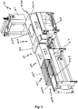
- FIG. 2 shows a weighing conveyor device according to the invention according to a first embodiment.
- the weighing conveyor comprises a first module of an access protection device 119, which consists of front and rear side plates 1193, 1195 and an upper plate 1191.
- the plates form an elongated tunnel, which covers the discharge belt 19 in its second half.
- the discharge belt 19 is the conveyor belt adjoining the weighing belt 17 in the conveying direction. Bulk goods that are transported from the weighing belt 17 to the removal belt 19 enter the entrance opening 1199 of the access security device and are then protected against unauthorized access by an operator.
- the access security device is attached to the housing 123 of the metal detector 23.
- the housing 123 of the Metal detector 23 itself forms the access protection device in the area of metal detector 23.
- a second module of the access protection device 127 Downward in the conveying direction after the metal detector 23 is a second module of the access protection device 127, which likewise consists of a front and a rear side plate 1273 and an upper plate 1271.
- the upper plate 1171 has an opening 1277 in the area of the top labeler 41, at the point at which the stamp of the top labeler 41 applies the label to the piece goods.
- the opening 1277 only includes the geometry necessary for the purpose of labeling. In the drawing, however, it is shown relatively large for reasons of better visibility.
- FIG. 3 shows a weighing conveyor device according to the invention in a second embodiment.
- the weighing belt 17 and the rear part of the feed belt 15 in the conveying direction are covered with an access protection device 115.
- the access protection device 115 comprises a carrier 1153, the cross section of which corresponds to that of the following access protection device 119 and is attached to fastening points 1155 on the dirt-repellent plates 21 or on the frame.
- the frame carries a plurality of rods 1151 which run parallel to the conveying direction and which are supported on the subsequent access protection device 119. Of course, the rods 1151 can also be supported on a second separate carrier in this area.
- the entrance opening 1159 of the access protection device 115 is thus located in front of the weighing belt 17.
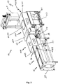
- Figure 4 shows a weighing conveyor device according to the invention in a third embodiment.
- the access protection device 115 of the weighing belt 17 and of the rear part of the feed belt in the conveying direction is realized with the aid of light barriers 1157.
- the light barriers 1157 consist of a pair of transmitters and receivers. The transmitter sends out a light signal and the receiver checks its presence. If there is no light signal at the receiver, an interference in the path between the transmitter and receiver is detected by a detector, which detector signal is forwarded to the control of the weighing conveyor.
- the access protection device 115 which is based on light barriers 1157, does not prevent manual access to a conveyor belt. However, it can detect manual access to a conveyor belt and report it to a controller.
- a corresponding action is implemented by the control as a result of the signal from the light barriers 1157, for example the weighing conveyor device is stopped, the labeling device is set to an uncalibrated marking state and / or the application of an already printed label of the labeling device is prevented.
- the light barriers 1157 are mounted on a carrier 1153 in the front area.
- the carrier 1153 is in turn attached to the dirt-repellent plates 21 or to the frame at fastening points 1155.
- the light barriers are mounted on the following access protection device 119.
- the light barriers 1157 are arranged in such a way that a light grid is formed which cannot be gripped without triggering at least one of the light barriers 1157.
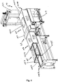
- Figure 5 shows a weighing conveyor device according to the invention in a fourth embodiment.
- the access protection device 115 of the weighing belt 17 and of the rear part of the feed belt in the conveying direction and that of the weighing belt up to the housing 123 of the Metal detector 23 following conveyor belts realized using light barriers 1157.
- the light barriers 1157 form a light grid from the carrier 1153, which is attached at the level of the feed belt 15 at fastening points 1155 on the dirt-repellent plates 21 or on the frame, to the housing 123 of the metal detector 23.
- the light barriers 1157 are accordingly on the carrier 1153 and on the housing 123 of the metal detector 23 attached.
- Figure 6 shows a weighing conveyor device according to the invention in a fifth embodiment in side view.
- the weighing conveyor comprises three printing and labeling devices 131, 133, 135.
- the printing and labeling devices 131, 133, 135 each comprise a top labeler 411, 413, 415, the packs from above with one printed label.
- the printing and labeling devices 131, 133, 135 each further comprise a bottom labeler 431, 433, 435, which each dispense a label into the distance between two conveyor belts and thus provide the packs with a printed label on the underside.
- the access security device has a modular structure.
- the first module of the access security device 115 in the area of the weighing belt is constructed from bars running parallel to the conveying direction.
- the second module of the access security device 127 covers the conveyor belts following the weighing belt up to the second printing and labeling device 133. This area is protected from manual access. For example, legally relevant data, such as a weight-dependent price label, are printed in the first printing and labeling device 135, and other legally relevant data, such as a label with the expiration date, are printed in the second printing and labeling device 133.
- legally relevant data such as a weight-dependent price label
- other legally relevant data such as a label with the expiration date
- the third printing and labeling device 131 for example, advertising labels are printed and applied to the piece goods, which have no legal relevance and are not subject to control. For this reason, the funding area is from second printing and labeling device 133 to the third printing and labeling device 131 are no longer equipped with an access security device.
- Figure 7 shows a weighing conveyor device according to the invention in a sixth embodiment.
- the access security device comprises four modules.
- the first module of the access security device 115 covers the area of the weighing belt.
- the second module of the access security device covers the area following the weighing belt up to the metal detector.
- the execution corresponds to the description with reference to the second embodiment.
- the weighing conveyor comprises three printing and labeling devices 131, 133, 135.
- the printing and labeling devices 131, 133, 135 each comprise a top labeler 411, 413, 415, which provide the packages with a printed label from above .
- the printing and labeling devices 131, 133, 135 each further comprise a bottom labeler 431, 433, 435, which each dispense a label into the distance between two conveyor belts and thus provide the packs with a printed label on the underside.
- the weighing conveyor device comprises two discharge devices 30, in which, for example, underweight packs or packs contaminated with metal are discharged.
- the third module of the access security device 127 covers the area of the conveyor path between the metal detector and including the third printing and labeling device 131.
- the fourth module of the access security device 131 covers the area of the ejection devices 30. Manual access to the conveyor belts from the weighing belt to the discharge devices 30 is not possible.
- Figure 7 shows the controller 7 also present in the other embodiments.
- DSP digital signal processor
- ASIC application specific integrated circuit
- FPGA field programmable gate array
- ROM read only memory
- RAM random access memory
Landscapes
- Physics & Mathematics (AREA)
- General Physics & Mathematics (AREA)
- Labeling Devices (AREA)
- Control Of Conveyors (AREA)
Abstract
Description
- Die vorliegende Erfindung betrifft eine Wäge-Fördervorrichtung mit einem Gestell, einem Wägeband und einem Zuführband zum Transport von zu wiegendem Stückgut. An dem Stückgut werden nach dem Wiegen in Förderrichtung abwärts von einer Bearbeitungsvorrichtung weitere Bearbeitungsschritte ausführt.
- Die
WO2014/131568A1 zeigt eine Wäge-Fördervorrichtung mit einem Wägeband und weiteren Förderbändern sowie mit einer Etikettiervorrichtung. - Die
US9354104B2 - Beiden Schriften gemein ist, dass sie in Förderrichtung an einer Stelle einen Gewichtswert eines Stückguts bestimmen und aufgrund seines Gewichtswertes das Stückgut in Förderrichtung abwärts an einer anderen Stelle weiterbearbeiten, zum Beispiel mit dem Gewichtswert oder mit einem vom Gewicht abhängigen Preis auszeichnen und etikettieren oder aufgrund des Gewichtswertes aussortieren, da zum Beispiel das minimale Gewicht unterschritten ist. Jedem Stückgut wird am Wägeband ein Gewichtswert zugeordnet, der über die weitere Bearbeitung entscheidet. Durch einen unsachgemäßen Eingriff eines Bedieners, der zum Beispiel auf dem Förderband zwischen Waage und Bearbeitungsstation zwei Stückgüter vertauscht, kann dieser Vorgang manipuliert werden.
- Aufgabe der Erfindung ist es ein gattungsgemäßes System zu entwickeln, das manipulationssicherer ist.
- Diese Aufgabe wird durch eine Wäge-Fördervorrichtung nach Anspruch 1 gelöst.
- Erfindungsgemäß wird eine Wäge-Fördervorrichtung mit einem Gestell vorgeschlagen. Die Wäge-Fördervorrichtung trägt zumindest ein Wägeband und ein Zuführband zum Transport von zu wiegendem Stückgut. Das zu wiegende Stückgut ist zum Beispiel eine Lebensmittelverpackung, die mit einem gewichtsabhängigen Preis verkauft wird oder eine Lebensmittelverpackung mit Festgewicht. Das Stückgut kann auch ein anderer Artikel sein, der gewichtsabhängig mit einem Preis ausgezeichnet wird. Das Wägeband ist mit einer unterhalb des Wägebandes angeordneten Wägezelle gekoppelt, die das Gewicht des über das Wägeband transportierten Stückgutes bestimmt. Die Wäge-Fördervorrichtung umfasst in Förderrichtung dem Wägeband folgend mindestens ein weiteres Förderband. Außerdem umfasst die Wäge-Fördervorrichtung mindestens eine Bearbeitungsvorrichtung für das Stückgut. Zumindest eine der mindestens einen Bearbeitungsvorrichtung führt Bearbeitungsschritte aus, die in Verbindung mit dem durch die Wägezelle bestimmten Gewichtswert für das Stückgut stehen. Ein solcher Bearbeitungsschritt ist zum Beispiel das Etikettieren mit einem Etikett das den Gewichtswert oder einen vom Gewichtswert abhängigen Preis zeigt oder das Aussortieren eines untergewichtigen Stückguts, das heißt zum Beispiel einer Packung, die ein gewisses Minimalgewicht nicht aufweist. Die Wäge-Fördervorrichtung umfasst eine Zugriffssicherungsvorrichtung, die das dem Wägeband folgende Förderband in Förderrichtung zumindest teilweise abdeckt. Die Zugriffssicherungsvorrichtung ist derart ausgestaltet, dass ein Bediener zumindest nicht mit vernünftigem Aufwand das Stückgut auf den Förderbändern entnehmen oder verschieben oder dessen Reihenfolge ändern kann. Das hat den Vorteil, dass das Stückgut vor dem Zugriff des Bedieners oder der händischen Entnahme einzelner Stückgüter durch den Bediener geschützt ist. Da zwischen Gewichtsbestimmung auf dem Wägeband und der gewichtsabhängigen Bearbeitung des Stückgutes an einer Bearbeitungsvorrichtung ein gewisser Abstand ist, erhöht es die Manipulationssicherheit, wenn dieser Abstand vor unberechtigtem und unerwünschtem Zugriff geschützt ist. Natürlich ist die Zugriffssicherung im Wartungsfall zu entnehmen bzw. zu öffnen, jedoch ist dabei eine Manipulation des Ablaufes nicht möglich.
- In einer Ausführungsform deckt die Zugriffssicherungsvorrichtung das dem Wägeband folgende Förderband mindestens in seiner Bandmitte und an seinem in Förderrichtung gesehenen Bandende ab. Das sich direkt ans Wägeband anschließende Förderband ist das Abführband. In anderen Ausführungsformen ist das dem Wägeband folgende Förderband das Förderband zu einem Metalldetektor oder zu einem Etikettierer. Das erste dem Wägeband folgende Förderband ist die erste Stelle der Förderstrecke, die derart manipuliert werden kann, das die Zuordnung zu den Gewichtsdaten verloren geht. In einer Ausführungsform ist das Förderband nicht in seinem Anfangsbereich abgedeckt, sondern erst ab seiner Bandmitte oder einige Zentimeter nach Bandbeginn. Beim Einfahren des Stückgutes unter die Abdeckung bildet sich ein Luftpolster unter der Abdeckung, das gegen das Stückgut selbst drückt. Ist die Abdeckung zu nahe am Wägeband, so kann dieses Luftpolster das Wiegeergebnis verschlechtern. Ist die Abdeckung auf dem Förderband, das sich an das Wägeband direkt anschließt, in Förderrichtung etwas zurückgesetzt, zum Beispiel bei einem kurzen Band bis in die Bandmitte, so ist das entstehende Luftpolster für das Wiegeergebnis nicht mehr relevant und die Wiegegenauigkeit bleibt erhalten.
- In einer Ausführungsform ist die Zugriffssicherungsvorrichtung als ein Tunnel ausgebildet. In dem Tunnel läuft mindestens ein abgedeckter Förderbandabschnitt. Der Tunnel schützt den Förderbandabschnitt vor manuellem Zugriff von oben und von den beiden Seiten. In einer Ausführungsform ist der Tunnel aus einem vorderen Seitenteil und einem hinteren Seitenteil sowie einem oberen Teil ausgebildet. In einer Ausführungsform ist der Tunnel durch ein U-förmig geformtes längliches Bauteil ausgebildet.
- In einer Ausführungsform ist der Tunnel eine mechanische Abdeckung und besteht aus Plattenmaterial oder Lochplattenmaterial. Die Lochplatten haben den Vorteil, dass Luft entweichen kann und so ein Überdruck im Tunnel durch eine schnelle Bewegung des Stückgutes auf den Förderbändern vermieden wird. Die Löcher der Lochplatten sind so klein dimensioniert, dass ein reinfassen durch einen Bediener oder eine Entnahme von Stückgütern durch die Löcher vermieden wird. In einer Ausführungsform sind die Abdeckungen und somit auch der Tunnel geformt aus einem Gitter, wie zum Beispiel einem Drahtgitter oder parallel verlaufenden Stäben. In einer Ausführungsform bilden Lichtschranken, die das Eingreifen detektieren, die Zugriffssicherungsvorrichtung. Sind mehrere Lichtschranken nebeneinander angeordnet, so entsteht ein virtueller Tunnel. Dieser hat den oben beschriebenen Nachteil der Entstehung eines Überdrucks, für den Fall, dass ein Stückgut in den Tunnel einfährt, nicht.
- In einer Ausführungsform umfasst die Wäge-Fördervorrichtung mindestens eine Etikettiervorrichtung. Die Etikettiervorrichtung umfasst einen Top-Etikettierer und/oder einen Bottom-Etikettierer. Ein Top-Etikettierer versieht das Stückgut auf dessen Oberseite mit einem Etikett, indem das Etikett von oben auf das Stückgut aufgedrückt wird. Ein Bottom-Etikettierer versieht das Stückgut auf dessen Unterseite mit einem Etikett, indem das Etikett in einen Zwischenraum zwischen zwei Förderbändern gespendet wird und auf dem Stückgut festklebt, wenn das Stückgut über das Etikett fährt. Im Falle eines Top-Etikettierers umfasst die Zugriffssicherungsvorrichtung eine Öffnung in der oberen Abdeckung, die groß genug ist, dass der Top-Etikettierer auf das Stückgut zugreifen kann um ein Etikett auf das Stückgut aufzubringen. Trotz dieser Öffnung wird der grundsätzliche Erfindungsgedanke, dass die Förderstrecke vor zugriffen geschützt ist, realisiert. Es ist für einen Bediener unmöglich, in diese Öffnung zu fassen, da sie im Vergleich zur Förderstrecke klein ist und im Bereich der Öffnung in regelmäßigen Abständen der Stempel des Etikettierers in die Abdeckung eingreift. Insofern bleibt der erfindungsgemäße Manipulationsschutz erhalten. Im Rahmen der Erfindung versteht sich eine Abdeckung, die einen Förderbandabschnitt abdeckt, auch als eine Abdeckung, die im Bereich eines Top-Etikettierers eine Öffnung zum Etikettieren von Stückgut von oben aufweist.
- In einer Ausführungsform haben die Bearbeitungsschritte, die in Verbindung mit dem durch die Wägezelle bestimmten Gewichtswert stehen, einen gesetzlich relevanten Bezug. Das ist insbesondere der Fall, wenn es sich um metrologische Bestimmungen, Bestimmungen nach dem Eichgesetz, einer Verpackungsverordnung oder einer Lebensmittelsicherheitsverordnung handelt.
- In einer Ausführungsform ist die Zugriffssicherungsvorrichtung der Wäge-Fördervorrichtung an allen Förderbändern abgebracht, die zwischen dem Wägeband und dem letzten Förderband, auf dem ein Bearbeitungsschritt ausgeführt wird, der mit dem von der Wägezelle bestimmten Gewichtswert oder einer gesetzlichen Vorschrift in Bezug steht, angebracht. Die Zugriffssicherungsvorrichtung deckt auch dieses letzte Förderband in Förderrichtung zumindest teilweise ab. In diesem Bereich soll eine Manipulation durch einen Bediener ausgeschlossen werden.
- In einer Ausführungsform deckt die Zugriffssicherung das Wägeband zumindest teilweise ab.
- In einer Ausführungsform ist die Wäge-Fördervorrichtung ein Preisauszeichner, ein Checkweigher oder ein Preisauszeichner oder Checkweigher mit Metalldetektor oder optischem Inspektionssystem. Die Zugriffssicherungsvorrichtung deckt auch Förderbänder ab, die zur Ausschleusvorrichtung des Metalldetektors oder des optischen Inspektionssystem und/oder des Checkweighers führen.
- In einer Ausführungsform besteht die Zugriffssicherungsvorrichtung des Wägebandes aus einem Lichtgitter, einem Gitter oder Stäben. Das hat den Vorteil, dass das oben genannte Problem des Überdruckes wenn ein Stückgut auf einem Förderband in einen mechanisch geschlossenen Tunnel fährt, vermieden wird. Die Luft, die das Stückgut bei seiner Bewegung vor sich herschiebt, kann so auch im Bereich der Zugriffsicherungsvorrichtung im Bereich des Wägebandes entweichen. So müssen wegen der Zugriffssicherungsvorrichtung keine wiegetechnischen Nachteile in Kauf genommen werden.
- In einer Ausführungsform besteht die Zugriffssicherungsvorrichtung aus mehreren Modulen. Die Module sind in Förderrichtung hintereinander aufgebaut. Die Module sind am Gestell oder an einer Abdeckung angebracht. In einer Ausführungsform hat die Wäge-Fördervorrichtung eine Vorrichtung um Anbauteile entlang der Förderstrecke anzubringen. Diese Vorrichtung trägt die Module. Es ist für die Erfindung unerheblich, ob die Zugriffssicherungsvorrichtung als ein langes Teil oder in mehreren modularen Abschnitten aufgebaut ist, da beide Lösungen das Ziel, nicht in dem Bereich zwischen Wägeband und Bearbeitungsvorrichtung entlang der Förderstrecke eingreifen zu können, verwirklichen können.
- In einer Ausführungsform ist die Zugriffssicherungsvorrichtung im Bereich eines Metalldetektors oder eines optischen Systems das Gehäuse des Metalldetektors oder des optischen Systems. Die weiteren Module der Zugriffssicherungsvorrichtung sind am Gehäuse des Metalldetektors oder des optischen Systems angeschlagen.
- In einer Ausführungsform umfasst die Wäge-Fördervorrichtung eine Steuerung und einen Detektor. Der Detektor detektiert einen Eingriff in einen durch die Lichtschranken der Zugriffssicherungsvorrichtung abgedeckten Bereich. Wird in diesen Bereich eingegriffen, das heißt, wird die Lichtschranke unterbrochen, so gibt der Detektor ein Detektorsignal aus. Die Steuerung steuert nach Empfang eines Detektorsignals die Wäge-Fördervorrichtung als Reaktion auf das Detektorsignal in einer bestimmten Weise. So setzt die Steuerung die Wäge-Fördervorrichtung still, stellt die Etikettiervorrichtung auf ungeeichten Auszeichnungszustand um und/oder verhindert das Applizieren eines bereits gedruckten Etiketts der Etikettiervorrichtung. All diesen Aktionen ist gemein, dass beim Eingriff in die Lichtschranken ein Manipulationsversuch vermutet wird und verhindert wird, dass eine aufgrund des Manipulationsversuches fehlerhafte Bearbeitung des Stückgutes stattfindet. Zum Beispiel ist ein ungeeichter Auszeichnungszustand auch dann erreicht, wenn ein Etikett auf dem Stückgut appliziert wird, das Etikett jedoch keine Gewichtsinformation und keine gewichtsabhängige Preisinformation umfasst. In einer Ausführungsform wird das Etikett in diesem Fall regulär gedruckt und appliziert, jedoch werden die Gewichtsinformation und die gewichtsabhängige Preisinformation nicht auf das Etikett aufgedruckt.
- Einige Ausführungsformen der Erfindung sind in den Zeichnungen beispielhaft gezeigt und nachfolgend beschrieben. Es zeigen, jeweils in schematischer Darstellung:
- Fig. 1
- eine Wäge-Fördervorrichtung nach dem Stand der Technik,
- Fig. 2
- eine erfindungsgemäße Wäge-Fördervorrichtung in einer ersten Ausführungsform,
- Fig. 3
- eine erfindungsgemäße Wäge-Fördervorrichtung in einer zweiten Ausführungsform,
- Fig. 4
- eine erfindungsgemäße Wäge-Fördervorrichtung in einer dritten Ausführungsform,
- Fig. 5
- eine erfindungsgemäße Wäge-Fördervorrichtung in einer vierten Ausführungsform,
- Fig. 6
- eine erfindungsgemäße Wäge-Fördervorrichtung in einer fünften Ausführungsform, und
- Fig. 7
- eine erfindungsgemäße Wäge-Fördervorrichtung in einer sechsten Ausführungsform.
- Die in
Figur 1 dargestellte Vorrichtung zeigt eine Wäge-Fördervorrichtung 11 wie sie aus dem Stand der Technik bekannt ist. Die Wäge-Fördervorrichtung 11 hat ein Zuführband 15, ein Wägeband 17, ein Abführband 19, einen Metalldetektor 23 und eine Druck- und Etikettiervorrichtung 13 mit einem ersten Förderband 27 und einem zweiten Förderband 29. Die Druck- und Etikettiervorrichtung 13 umfasst einen Top-Etikettierer 41, der Packungen auf dem ersten Förderband 27 von oben mit einem bedruckten Etikett versieht. Die Druck- und Etikettiervorrichtung 13 umfasst ferner einen Bottom-Etikettierer 43, der ein Etikett in den Abstand zwischen dem ersten Förderband 27 und dem zweiten Förderband 29 spendet und so die Packung mit einem bedruckten Etikett auf der Unterseite versieht, wenn sie über den Spalt zwischen dem ersten Förderband 27 und dem zweiten Förderband 29 der Druck- und Etikettiervorrichtung 13 befördert wird. Das Wägeband 17 ist mit einer unterhalb des Wägebandes 17 angeordneten, nicht dargestellten Wägezelle gekoppelt, die dazu ausgelegt ist, das Gewicht eines sich über das Wägeband 17 bewegenden Stückguts zu bestimmen. Wägeband 17 und Wägezelle bilden eine Wägeplattform, die als Kontrollwaage bzw. Checkweigher oder als Preisauszeichner ausgebildet sein kann. Zu beiden Seiten der drei Transportbänder 15, 17, 19 sind Schmutzabweisbleche 21 vorgesehen. - Im Betrieb der Wäge-Fördervorrichtung 11 werden zu verwiegende Packungen von dem Zuführband 15 an das Wägeband 17 übergeben, dort gewogen und über das Abführband 19 an ein Transportband des Metalldetektors 23 weitertransportiert. Anschließend werden die Packungen von der Druck- und Etikettiervorrichtung 13 übernommen und mit einem Etikett versehen, das zuvor mit dem von der Wägezelle für die jeweilige Packung ermittelten Gewicht, einem dazugehörigen Preis, einem Haltbarkeitsdatum, Produktinformationen oder Werbung bedruckt wurde. Der Metalldetektor 23 kann auch weggelassen werden, oder anstelle des Metalldetektors 23 oder zusätzlich hierzu kann auch beispielsweise eine Sortiereinrichtung vorgesehen sein.
- Darüber hinaus umfasst die Wäge-Fördervorrichtung 11 ein Gestell 25, auf dem sich das Zuführband 15, das Wägeband 17 mit der Wägezelle, das Abführband 19, der Metalldetektor 23 mit zugehörigem Transportband und die beiden Förderbänder 27, 29 der Druck- und Etikettiervorrichtung 13 abstützen. Das Gestell 25 umfasst mehrere Seitenwangen 33, die im Bereich des Zuführbands 15, des Wägebandes 17, des Abführbandes 19 und des Metalldetektors 23, d.h. im Bereich eines Wägemoduls und eines Metalldetektormoduls des Gestells, über jeweils mehrere als Rundrohre ausgebildete Längsträger 37 fest miteinander verbunden sind. Die Seitenwangen 33 des Wägemoduls sind jeweils zweiteilig ausgebildet, wobei die beiden jeweiligen Seitenwangenteile über als Vierkantrohre ausgebildete Querträger 39, die an den Innenseiten der Seitenwangenteile 33 vorgesehen sind, miteinander verbunden sind. An die Seitenwangen 33 sind jeweils zwei Standfüße 35 angeschraubt, die unabhängig voneinander höhenverstellbar sind.
- Im Bereich der Druck- und Etikettiervorrichtung 13 ist in der Ansicht gemäß
Figur 1 an der Rückseite des Gestells 25 ein Schaltschrank 31 für die Steuerung der Wäge-Fördervorrichtung 11 vorgesehen. - In den weiteren Zeichnungen sind gleiche Bauteile mit gleichen Bezugszeichen bezeichnet und werden nachfolgend nicht noch einmal separat beschrieben. Auf die jeweils vorangegangene Beschreibung der Bauteile wird verwiesen.
-
Figur 2 zeigt eine erfindungsgemäße Wäge-Fördervorrichtung nach einer ersten Ausführungsform. Die Wäge-Fördervorrichtung umfasst ein erstes Modul einer Zugriffssicherungsvorrichtung 119, welche aus einer vorderen und einer hinteren Seitenplatte 1193, 1195 und einer oberen Platte 1191 besteht. Die Platten bilden einen länglichen Tunnel, der das Abführband 19 in seiner zweiten Hälfte abdeckt. Das Abführband 19 ist das sich an das Wägeband 17 anschließende Förderband in Förderrichtung. Stückgüter die vom Wägeband 17 auf das Abführband 19 transportiert werden, fahren in die Eingangsöffnung 1199 der Zugriffssicherungsvorrichtung ein und sind dann vor dem unerlaubten Zugriff eines Bedieners geschützt. Ausgangsseitig ist die Zugriffssicherungsvorrichtung an dem Gehäuse 123 des Metalldetektors 23 angeschlagen. Das Gehäuse 123 des Metalldetektors 23 bildet im Bereich des Metalldetektors 23 selbst die Zugriffsschutzvorrichtung. In Förderrichtung abwärts nach dem Metalldetektor 23 befindet sich ein zweites Modul der Zugriffsschutzvorrichtung 127, das ebenfalls aus einer vorderen und einer hinteren Seitenplatte 1273 und einer oberen Platte 1271 besteht. Die obere Platte 1171 weist im Bereich des Top-Etikettierers 41, an der Stelle, an der der Stempel des Top-Etikettierers 41 das Etikett auf das Stückgut appliziert, eine Öffnung 1277 auf. Die Öffnung 1277 umfasst nur die für den Zweck der Etikettierung notwendige Geometrie. In der Zeichnung ist sie jedoch aus Gründen der besseren Sichtbarkeit relativ groß dargestellt. Nach dem Etikettiervorgang verlässt das Stückgut über das letzte Förderband 29 der der Druck- und Etikettiervorrichtung 13 die Zugriffsschutzvorrichtung 127 durch die Ausgangsöffnung 1279. In der Praxis schließen sich dann weitere Förderbänder zur Logistik des Stückguts an. -
Figur 3 zeigt eine erfindungsgemäße Wäge-Fördervorrichtung in einer zweiten Ausführungsform. Zusätzlich zur ersten Ausführungsform sind hier das Wägeband 17 und der in Förderrichtung hintere Teil des Zuführband 15 mit einer Zugriffsschutzvorrichtung 115 abgedeckt. Die Zugriffsschutzvorrichtung 115 umfasst einen Träger 1153, der in seinem Querschnitt dem der nachfolgenden Zugriffsschutzvorrichtung 119 entspricht und an Befestigungspunkten 1155 an den Schmutzabweisblechen 21 oder am Gestell angebracht ist. Der Rahmen trägt mehrere parallel entlang der Förderrichtung verlaufende Stäbe 1151, die auf der nachfolgenden Zugriffsschutzvorrichtung 119 abgestützt sind. Natürlich können die Stäbe 1151 auch auf einem zweiten separaten Träger in diesem Bereich abgestützt sein. Die Eingangsöffnung 1159 der Zugriffsschutzvorrichtung 115 befindet sich somit vor dem Wägeband 17. Durch die Ausführung der Zugriffsschutzvorrichtung 115 im Bereich des Wägebandes 17 mit Stäben entsteht kein Problem von einem durch Überdruck verfälschten Wiegeergebnis. Gleiches ist richtig, wenn für die Zugriffsschutzvorrichtung anstatt Stäben 1151 ein Gitter verwendet wird. -
Figur 4 zeigt eine erfindungsgemäße Wäge-Fördervorrichtung in einer dritten Ausführungsform. Im Vergleich zur zweiten Ausführungsform ist die Zugriffsschutzvorrichtung 115 des Wägebandes 17 und des in Förderrichtung hinteren Teils des Zuführbandes mithilfe von Lichtschranken 1157 realisiert. Die Lichtschranken 1157 bestehen aus einem Sender-Empfängerpaar. Der Sender sendet ein Lichtsignal aus und der Empfänger prüft dessen Vorhandensein. Ist beim Empfänger kein Lichtsignal vorhanden, so wird ein Eingriff in den Pfad zwischen Sender und Empfänger von einem Detektor detektiert, der ein Detektorsignal an die Steuerung der Wäge-Fördervorrichtung weitergeleitet wird. Insofern verhindert die Zugriffsschutzvorrichtung 115, die auf Lichtschranken 1157 basiert, nicht den manuellen Zugriff auf ein Förderband. Sie kann jedoch den manuellen Zugriff auf ein Förderband detektieren und an eine Steuerung melden. Von der Steuerung wird infolge des Signals der Lichtschranken 1157 eine entsprechende Aktion umgesetzt, zum Beispiel wird die Wäge-Fördervorrichtung stillgesetzt, die Etikettiervorrichtung wird in einen ungeeichten Auszeichnungszustand versetzt und/oder das Applizieren eines bereits gedruckten Etiketts der Etikettiervorrichtung wird verhindert. Die Lichtschranken 1157 sind im vorderen Bereich auf einem Träger 1153 angebracht. Der Träger 1153 ist seinerseits an Befestigungspunkten 1155 an den Schmutzabweisblechen 21 oder am Gestell angebracht. Im hinteren Bereich sind die Lichtschranken auf der folgenden Zugriffsschutzvorrichtung 119 angebracht. Die Lichtschranken 1157 sind so angeordnet, dass ein Lichtgitter entsteht, in das nicht gefasst werden kann, ohne wenigstens eine der Lichtschranken 1157 auszulösen. -
Figur 5 zeigt eine erfindungsgemäße Wäge-Fördervorrichtung in einer vierten Ausführungsform. Im Vergleich zur dritten Ausführungsform ist die Zugriffsschutzvorrichtung 115 des Wägebandes 17 und des in Förderrichtung hinteren Teils des Zuführbandes sowie der dem Wägeband bis zum Gehäuse 123 des Metalldetektors 23 folgenden Förderbänder mithilfe von Lichtschranken 1157 realisiert. Die Lichtschranken 1157 bilden ein Lichtgitter vom Träger 1153, der auf Höhe des Zuführbandes 15 an Befestigungspunkten 1155 an den Schmutzabweisblechen 21 oder am Gestell angebracht ist, bis hin zum Gehäuse 123 des Metalldetektors 23. Die Lichtschranken 1157 sind entsprechend auf dem Träger 1153 und am Gehäuse 123 des Metalldetektors 23 angebracht. -
Figur 6 zeigt eine erfindungsgemäße Wäge-Fördervorrichtung in einer fünften Ausführungsform in der Seitenansicht. Im Vergleich zu den vorangegangenen Ausführungsformen umfasst die Wäge-Fördervorrichtung drei Druck- und Etikettiervorrichtungen 131, 133, 135. Die Druck- und Etikettiervorrichtungen 131, 133, 135 umfassen jeweils einen Top-Etikettierer 411, 413, 415, die Packungen von oben mit einem bedruckten Etikett versehen. Die Druck- und Etikettiervorrichtungen 131, 133, 135 umfassen ferner jeweils einen Bottom-Etikettierer 431, 433, 435, die ein Etikett jeweils in den Abstand zwischen zwei Förderbändern spenden und so die Packungen mit einem bedruckten Etikett auf der Unterseite versehen. Die Zugriffssicherungsvorrichtung ist modular aufgebaut. Das erste Modul der Zugriffssicherungsvorrichtung 115 im Bereich des Wägebandes ist aus zur Förderrichtung parallel verlaufenden Stäben aufgebaut. Das zweite Modul der Zugriffssicherungsvorrichtung 127 deckt die Förderbänder dem Wägeband folgend bis hin zur zweiten Druck- und Etikettiervorrichtung 133 ab. Dieser Bereich ist vor manuellem Zugriff geschützt. So werden zum Beispiel bei der ersten Druck- und Etikettiervorrichtung 135 gesetzlich relevanten Daten, wie zum Beispiel ein gewichtsabhängiges Preisetikett, und in der zweiten Druck- und Etikettiervorrichtung 133 weitere gesetzliche relevante Daten, wie zum Beispiel ein Etikett mit dem Haltbarkeitsdatum, gedruckt. An der dritten Druck- und Etikettiervorrichtung 131 werden zum Beispiel Werbeetiketten gedruckt und auf das Stückgut appliziert, die keine gesetzliche Relevanz haben und keiner Kontrolle unterliegen. Aus diesem Grund ist der Förderbereich von der zweiten Druck- und Etikettiervorrichtung 133 hin zur dritten Druck- und Etikettiervorrichtung 131 nicht mehr mit einer Zugriffssicherungsvorrichtung ausgestattet. -
Figur 7 zeigt eine erfindungsgemäße Wäge-Fördervorrichtung in einer sechsten Ausführungsform. Im Vergleich zur fünften Ausführungsform umfasst die Zugriffssicherungsvorrichtung vier Module. Das erste Modul der Zugriffssicherungsvorrichtung 115 deckt den Bereich des Wägebandes ab. Das zweite Modul der Zugriffssicherungsvorrichtung deckt den Bereich dem Wägeband folgend bis hin zum Metalldetektor ab. Die Ausführung entspricht insoweit der Beschreibung mit Bezug zur zweiten Ausführungsform. Dem Metalldetektor folgend umfasst die Wäge-Fördervorrichtung drei Druck- und Etikettiervorrichtungen 131, 133, 135. Die Druck- und Etikettiervorrichtungen 131, 133, 135 umfassen jeweils einen Top-Etikettierer 411, 413, 415, die Packungen von oben mit einem bedruckten Etikett versehen. Die Druck- und Etikettiervorrichtungen 131, 133, 135 umfassen ferner jeweils einen Bottom-Etikettierer 431, 433, 435, die ein Etikett jeweils in den Abstand zwischen zwei Förderbändern spenden und so die Packungen mit einem bedruckten Etikett auf der Unterseite versehen. Den drei Druck- und Etikettiervorrichtungen 131, 133, 135 folgend umfasst die Wäge-Fördervorrichtung zwei Ausschleusevorrichtungen 30, in denen zum Beispiel untergewichtige Packungen oder mit Metall verunreinigte Packungen ausgeschleust werden. Das dritte Modul der Zugriffssicherungsvorrichtung 127 deckt den Bereich der Förderstrecke zwischen Metalldetektor und inklusive der dritten Druck- und Etikettiervorrichtung 131 ab. Das vierte Modul der Zugriffssicherungsvorrichtung 131 deckt den Bereich der Ausschleusevorrichtungen 30 ab. Ein manueller Zugriff auf die Förderbänder ist vom Wägeband an bis hin zu den Ausschleusevorrichtungen 30 nicht möglich.Figur 7 zeigt die ebenfalls in den anderen Ausführungsformen vorhandene Steuerung 7. - Die Funktionen verschiedener in den Zeichnungen gezeigter Elemente, inklusive der Funktionsblöcke, können durch dezidierte Hardware oder durch generische Hardware, die in der Lage ist Software auszuführen, im Zusammenhang mit der entsprechenden Software, realisiert werden. Falls die Funktionen mittels eines Prozessors zur Verfügung gestellt werden, können sie durch einen einzigen dezidierten Prozessor, einen einzigen geteilten Prozessor oder mehrere generische Prozessoren, die wiederum geteilt sein können, zur Verfügung gestellt werden. Die Funktionen können, ohne Einschränkung, durch einen digital signal processor (DSP), Netzwerk Prozessor, application specific integrated circuit (ASIC), field programmable gate array (FPGA), read only memory (ROM) mit gespeicherter Software, random access memory (RAM), und nichtflüchtige Speicher zur Verfügung gestellt werden.
Claims (13)
- Wäge-Fördervorrichtung (11) mit einem Gestell (33, 37, 39), welches zumindest ein Wägeband (17) und ein Zuführband (15) zum Transport von zu wiegendem Stückgut trägt, wobei das Wägeband (17) mit einer unterhalb des Wägebandes angeordneten Wägezelle (9) gekoppelt ist, wobei die Wäge-Fördervorrichtung (11) in Förderrichtung dem Wägeband (17) folgend mindestens ein weiteres Förderband (19, 27, 29) und mindestens eine Bearbeitungsvorrichtung (13, 23, 41, 43) für das Stückgut umfasst, wobei zumindest eine der mindestens einen Bearbeitungsvorrichtung (13, 23, 41, 43) Bearbeitungsschritte ausführt, die in Verbindung mit dem durch die Wägezelle bestimmten Gewichtswert für das Stückgut stehen, dadurch gekennzeichnet, dass die Wäge-Fördervorrichtung (11) eine Zugriffssicherungsvorrichtung (115, 119, 127, 131, 1151, 1153, 1155, 1157, 1191, 1193, 1271, 1273) umfasst, die das dem Wägeband (17) folgende Förderband (19) in Förderrichtung zumindest teilweise abdeckt.
- Wäge-Fördervorrichtung nach Anspruch 1, dadurch gekennzeichnet, dass die Zugriffssicherungsvorrichtung (115, 119, 127, 131, 1151, 1153, 1155, 1157, 1191, 1193, 1271, 1273) das dem Wägeband (17) folgende Förderband (19) mindestens in seiner Bandmitte und an seinem in Förderrichtung gesehenen Bandende abdeckt.
- Wäge-Fördervorrichtung nach Anspruch 1 oder 2, dadurch gekennzeichnet, dass die Zugriffssicherungsvorrichtung (115, 119, 127, 131, 1151, 1153, 1155, 1157, 1191, 1193, 1271, 1273) als ein Tunnel ausgebildet ist, in dem mindestens ein abgedeckter Förderbandabschnitt läuft und der den Förderbandabschnitt vor manuellem Zugriff von oben und von den beiden Seiten schützt.
- Wäge-Fördervorrichtung nach einem der Ansprüche 1 bis 3, dadurch gekennzeichnet, dass die Wäge-Fördervorrichtung (11) mindestens eine Etikettiervorrichtung (13) umfasst, wobei die Etikettiervorrichtung (13) einen Top-Etikettierer (41) und/oder einen Bottom-Etikettierer (43) umfasst, und wobei die Zugriffssicherungsvorrichtung (115, 119, 127, 131, 1151, 1153, 1155, 1157, 1191, 1193, 1271, 1273)) im Falle, dass die Etikettiervorrichtung (13) einen Top-Etikettierer (41) umfasst, eine Öffnung (1277) in einer Abdeckung (1271) von oben in dem Bereich hat, in dem der Top-Etikettierer (41) auf das Stückgut zugreift um ein Etikett auf das Stückgut aufzubringen.
- Wäge-Fördervorrichtung nach einem der Ansprüche 1 bis 4, dadurch gekennzeichnet, dass die in Verbindung mit dem durch die Wägezelle (9) bestimmten Gewichtswert stehenden Bearbeitungsschritte einen gesetzlich, insbesondere nach metrologischen Bestimmungen, dem Eichgesetz, einer Verpackungsverordnung oder einer Lebensmittelsicherheitsverordnung, relevanten Bezug haben.
- Wäge-Fördervorrichtung nach einem der Ansprüche 1 bis 5, dadurch gekennzeichnet, dass die Zugriffssicherungsvorrichtung (115, 119, 127, 131, 1151, 1153, 1155, 1157, 1191, 1193, 1271, 1273) der Wäge-Fördervorrichtung (11) an allen Förderbändern (19, 27) abgebracht ist, die zwischen dem Wägeband (17) und dem letzten Förderband (29), auf dem ein Bearbeitungsschritt ausgeführt wird, der mit dem von der Wägezelle (9) bestimmten Gewichtswert oder einer gesetzlichen Vorschrift in Bezug steht, angebracht ist und die Zugriffssicherungsvorrichtung (115, 119, 127, 131, 1151, 1153, 1155, 1157, 1191, 1193, 1271, 1273) auch dieses letzte Förderband (29) in Förderrichtung zumindest teilweise abdeckt.
- Wäge-Fördervorrichtung nach einem der Ansprüche 1 bis 6, dadurch gekennzeichnet, dass die Zugriffssicherung (115, 119, 127, 131, 1151, 1153, 1155, 1157, 1191, 1193, 1271, 1273) das Wägeband (17) zumindest teilweise abdeckt.
- Wäge-Fördervorrichtung nach einem der Ansprüche 1 bis 7, dadurch gekennzeichnet, dass die Zugriffssicherungsvorrichtung (115, 119, 127, 131, 1151, 1153, 1155, 1157, 1191, 1193, 1271, 1273) aus einer oder mehreren Lichtschranken oder aus einer mechanischen Abdeckung, insbesondere aus Platten, Lochplatten, einem Gitter oder Stäben besteht.
- Wäge-Fördervorrichtung nach einem der Ansprüche 1 bis 8, dadurch gekennzeichnet, dass die Wäge-Fördervorrichtung (11) ein Preisauszeichner, ein Checkweigher oder ein Preisauszeichner oder Checkweigher mit Metalldetektor (23) oder optischem Inspektionssystem ist und dass die Zugriffssicherungsvorrichtung auch Förderbänder abgedeckt, die zur Ausschleusevorrichtung (30) des Metalldetektors (23) oder optischen Inspektionssystem und/oder des Checkweighers führen.
- Wäge-Fördervorrichtung nach einem der Ansprüche 1 bis 9, dadurch gekennzeichnet, dass die Zugriffssicherungsvorrichtung des Wägebandes (17) aus einem Lichtgitter, einem Gitter oder Stäben besteht.
- Wäge-Fördervorrichtung nach einem der Ansprüche 1 bis 10, dadurch gekennzeichnet, dass die Zugriffssicherungsvorrichtung (115, 119, 127, 131, 1151, 1153, 1155, 1157, 1191, 1193, 1271, 1273) aus mehreren Modulen besteht (115, 119, 127, 131), die hintereinander in Förderrichtung auf der Wäge-Fördervorrichtung (11) aufgebaut sind.
- Wäge-Fördervorrichtung nach einem der Ansprüche 1 bis 11, dadurch gekennzeichnet, dass die Zugriffssicherungsvorrichtung (115, 119, 127, 131, 1151, 1153, 1155, 1157, 1191, 1193, 1271, 1273) im Bereich eines Metalldetektors (23) oder eines optischen Systems das Gehäuse des Metalldetektors (123) oder des optischen Systems und eine daran angeschlagene Zugriffssicherungsvorrichtung (115, 119, 127, 131, 1151, 1153, 1155, 1157, 1191, 1193, 1271, 1273) ist.
- Wäge-Fördervorrichtung nach einem der Ansprüche 1 bis 11, dadurch gekennzeichnet, dass die Wäge-Fördervorrichtung (11) eine Steuerung (7) und einen Detektor umfasst, wobei der Detektor einen Eingriff in einen durch die Lichtschranken (1157) der Zugriffssicherungsvorrichtung (115) abgedeckten Bereich detektiert und ein Detektorsignal ausgibt, und wobei die Steuerung (7) nach Empfang eines Detektorsignals die Wäge-Fördervorrichtung stillsetzt, die Etikettiervorrichtung in einen ungeeichten Auszeichnungszustand versetzt und/oder das Applizieren eines bereits gedruckten Etiketts der Etikettiervorrichtung verhindert.
Priority Applications (1)
| Application Number | Priority Date | Filing Date | Title |
|---|---|---|---|
| EP18248301.6A EP3674673B1 (de) | 2018-12-28 | 2018-12-28 | Manipulationssichere wäge-fördervorrichtung |
Applications Claiming Priority (1)
| Application Number | Priority Date | Filing Date | Title |
|---|---|---|---|
| EP18248301.6A EP3674673B1 (de) | 2018-12-28 | 2018-12-28 | Manipulationssichere wäge-fördervorrichtung |
Publications (2)
| Publication Number | Publication Date |
|---|---|
| EP3674673A1 true EP3674673A1 (de) | 2020-07-01 |
| EP3674673B1 EP3674673B1 (de) | 2022-03-30 |
Family
ID=65010500
Family Applications (1)
| Application Number | Title | Priority Date | Filing Date |
|---|---|---|---|
| EP18248301.6A Active EP3674673B1 (de) | 2018-12-28 | 2018-12-28 | Manipulationssichere wäge-fördervorrichtung |
Country Status (1)
| Country | Link |
|---|---|
| EP (1) | EP3674673B1 (de) |
Cited By (1)
| Publication number | Priority date | Publication date | Assignee | Title |
|---|---|---|---|---|
| DE102022108509A1 (de) | 2022-04-08 | 2023-10-12 | Hermann Schwelling | Vorrichtung zum Wiegen und Etikettieren von Ballen sowie Verfahren für deren Betrieb |
Citations (6)
| Publication number | Priority date | Publication date | Assignee | Title |
|---|---|---|---|---|
| DE102007021393A1 (de) * | 2007-05-04 | 2008-11-13 | Wipotec Wiege- Und Positioniersysteme Gmbh | Transportwaage, insbesondere Wägeförderer mit einem Transportband |
| JP2008285182A (ja) * | 2007-05-16 | 2008-11-27 | Teraoka Seiko Co Ltd | 下貼りラベル貼付装置 |
| DE102013203456A1 (de) * | 2013-02-28 | 2014-08-28 | Bizerba Gmbh & Co Kg | Etikettiervorrichtung |
| WO2014131568A1 (de) | 2013-02-28 | 2014-09-04 | Bizerba Gmbh & Co. Kg | Gestell einer wäge-fördervorrichtung |
| EP2796045A1 (de) * | 2013-04-26 | 2014-10-29 | Andreas Kisch | Vorrichtung zur Bereitstellung von Back- und Backzusatzstoffen |
| US9354104B2 (en) | 2013-03-01 | 2016-05-31 | Mettler-Toledo, LLC | Reject bin interlock system and method of securing objects rejected by an inspection device |
-
2018
- 2018-12-28 EP EP18248301.6A patent/EP3674673B1/de active Active
Patent Citations (6)
| Publication number | Priority date | Publication date | Assignee | Title |
|---|---|---|---|---|
| DE102007021393A1 (de) * | 2007-05-04 | 2008-11-13 | Wipotec Wiege- Und Positioniersysteme Gmbh | Transportwaage, insbesondere Wägeförderer mit einem Transportband |
| JP2008285182A (ja) * | 2007-05-16 | 2008-11-27 | Teraoka Seiko Co Ltd | 下貼りラベル貼付装置 |
| DE102013203456A1 (de) * | 2013-02-28 | 2014-08-28 | Bizerba Gmbh & Co Kg | Etikettiervorrichtung |
| WO2014131568A1 (de) | 2013-02-28 | 2014-09-04 | Bizerba Gmbh & Co. Kg | Gestell einer wäge-fördervorrichtung |
| US9354104B2 (en) | 2013-03-01 | 2016-05-31 | Mettler-Toledo, LLC | Reject bin interlock system and method of securing objects rejected by an inspection device |
| EP2796045A1 (de) * | 2013-04-26 | 2014-10-29 | Andreas Kisch | Vorrichtung zur Bereitstellung von Back- und Backzusatzstoffen |
Cited By (1)
| Publication number | Priority date | Publication date | Assignee | Title |
|---|---|---|---|---|
| DE102022108509A1 (de) | 2022-04-08 | 2023-10-12 | Hermann Schwelling | Vorrichtung zum Wiegen und Etikettieren von Ballen sowie Verfahren für deren Betrieb |
Also Published As
| Publication number | Publication date |
|---|---|
| EP3674673B1 (de) | 2022-03-30 |
Similar Documents
| Publication | Publication Date | Title |
|---|---|---|
| DE3303184C2 (de) | ||
| DE69706856T2 (de) | Verfahren und vorrichtung zur detektion von flüssigkeitsbehältern | |
| DE60026535T2 (de) | Sortierer mit kippschale | |
| DE69107635T2 (de) | Selbstbedienungskasse. | |
| EP2417586B1 (de) | Vorrichtung zur rücknahme von leergut, insbesondere kunststoffflaschen und metalldosen | |
| EP1952103B1 (de) | Verfahren zum wiegen mit mehreren wägezellen | |
| EP3437745B2 (de) | Matrixsorter | |
| DE102011083580A1 (de) | Sortieranlage und Sortierverfahren zum gemeinsamen Sortieren von verschiedenartigen Gegenständen | |
| DE2844210A1 (de) | Abgabevorrichtung | |
| DE2752193C2 (de) | Transportvorrichtung für Serienerzeugnisse innerhalb einer Wägevorrichtung | |
| EP3395701A1 (de) | Gewichtsauszeichnungskontrolle für verpackungen | |
| EP1858786B1 (de) | Fördereinrichtung | |
| EP3578932A1 (de) | Wäge-fördervorrichtung | |
| EP2865614B1 (de) | Gestell für eine Förderbandanlage | |
| DE2831843C2 (de) | ||
| EP3674673B1 (de) | Manipulationssichere wäge-fördervorrichtung | |
| WO2021140031A1 (de) | System zum sortieren von sortierstücken in mit ihrer zieldestination logisch verknüpfte zielstellen in matrixanordnung | |
| DE69820190T2 (de) | Sortieranlage für lange Produkte | |
| DE19716672C1 (de) | Verfahren und Vorrichtung zum quantitativen Erfassen von verpackten Altbackwaren-Retouren | |
| EP1872099B1 (de) | Wiegevorrichtung und -verfahren | |
| EP0665421A1 (de) | Stückgutförderer (Sorter) zum Sortieren von Stückgutteilen | |
| EP3169589A1 (de) | Vorrichtung, schalter und verfahren zur aufgabe von gepäckstücken | |
| EP3208003B1 (de) | Sortiervorrichtung mit einstellbaren endstellen sowie verfahren unter verwendung einer solchen sortiervorrichtung | |
| DE202017004165U1 (de) | Vorrichtung zum Wiegen eines Produkts in einer Fertigungslinie | |
| EP2282185A1 (de) | Verfahren und Vorrichtung zum näherungsweisen Wiegen eines Gegenstands |
Legal Events
| Date | Code | Title | Description |
|---|---|---|---|
| PUAI | Public reference made under article 153(3) epc to a published international application that has entered the european phase |
Free format text: ORIGINAL CODE: 0009012 |
|
| STAA | Information on the status of an ep patent application or granted ep patent |
Free format text: STATUS: THE APPLICATION HAS BEEN PUBLISHED |
|
| AK | Designated contracting states |
Kind code of ref document: A1 Designated state(s): AL AT BE BG CH CY CZ DE DK EE ES FI FR GB GR HR HU IE IS IT LI LT LU LV MC MK MT NL NO PL PT RO RS SE SI SK SM TR |
|
| AX | Request for extension of the european patent |
Extension state: BA ME |
|
| STAA | Information on the status of an ep patent application or granted ep patent |
Free format text: STATUS: REQUEST FOR EXAMINATION WAS MADE |
|
| 17P | Request for examination filed |
Effective date: 20201126 |
|
| RBV | Designated contracting states (corrected) |
Designated state(s): AL AT BE BG CH CY CZ DE DK EE ES FI FR GB GR HR HU IE IS IT LI LT LU LV MC MK MT NL NO PL PT RO RS SE SI SK SM TR |
|
| TPAC | Observations filed by third parties |
Free format text: ORIGINAL CODE: EPIDOSNTIPA |
|
| STAA | Information on the status of an ep patent application or granted ep patent |
Free format text: STATUS: EXAMINATION IS IN PROGRESS |
|
| TPAC | Observations filed by third parties |
Free format text: ORIGINAL CODE: EPIDOSNTIPA |
|
| 17Q | First examination report despatched |
Effective date: 20210608 |
|
| GRAP | Despatch of communication of intention to grant a patent |
Free format text: ORIGINAL CODE: EPIDOSNIGR1 |
|
| STAA | Information on the status of an ep patent application or granted ep patent |
Free format text: STATUS: GRANT OF PATENT IS INTENDED |
|
| INTG | Intention to grant announced |
Effective date: 20220112 |
|
| GRAS | Grant fee paid |
Free format text: ORIGINAL CODE: EPIDOSNIGR3 |
|
| GRAA | (expected) grant |
Free format text: ORIGINAL CODE: 0009210 |
|
| STAA | Information on the status of an ep patent application or granted ep patent |
Free format text: STATUS: THE PATENT HAS BEEN GRANTED |
|
| AK | Designated contracting states |
Kind code of ref document: B1 Designated state(s): AL AT BE BG CH CY CZ DE DK EE ES FI FR GB GR HR HU IE IS IT LI LT LU LV MC MK MT NL NO PL PT RO RS SE SI SK SM TR |
|
| REG | Reference to a national code |
Ref country code: GB Ref legal event code: FG4D Free format text: NOT ENGLISH |
|
| REG | Reference to a national code |
Ref country code: CH Ref legal event code: EP |
|
| REG | Reference to a national code |
Ref country code: DE Ref legal event code: R096 Ref document number: 502018009237 Country of ref document: DE |
|
| REG | Reference to a national code |
Ref country code: AT Ref legal event code: REF Ref document number: 1479613 Country of ref document: AT Kind code of ref document: T Effective date: 20220415 |
|
| REG | Reference to a national code |
Ref country code: IE Ref legal event code: FG4D Free format text: LANGUAGE OF EP DOCUMENT: GERMAN |
|
| REG | Reference to a national code |
Ref country code: LT Ref legal event code: MG9D |
|
| PG25 | Lapsed in a contracting state [announced via postgrant information from national office to epo] |
Ref country code: SE Free format text: LAPSE BECAUSE OF FAILURE TO SUBMIT A TRANSLATION OF THE DESCRIPTION OR TO PAY THE FEE WITHIN THE PRESCRIBED TIME-LIMIT Effective date: 20220330 Ref country code: RS Free format text: LAPSE BECAUSE OF FAILURE TO SUBMIT A TRANSLATION OF THE DESCRIPTION OR TO PAY THE FEE WITHIN THE PRESCRIBED TIME-LIMIT Effective date: 20220330 Ref country code: NO Free format text: LAPSE BECAUSE OF FAILURE TO SUBMIT A TRANSLATION OF THE DESCRIPTION OR TO PAY THE FEE WITHIN THE PRESCRIBED TIME-LIMIT Effective date: 20220630 Ref country code: LT Free format text: LAPSE BECAUSE OF FAILURE TO SUBMIT A TRANSLATION OF THE DESCRIPTION OR TO PAY THE FEE WITHIN THE PRESCRIBED TIME-LIMIT Effective date: 20220330 Ref country code: HR Free format text: LAPSE BECAUSE OF FAILURE TO SUBMIT A TRANSLATION OF THE DESCRIPTION OR TO PAY THE FEE WITHIN THE PRESCRIBED TIME-LIMIT Effective date: 20220330 Ref country code: BG Free format text: LAPSE BECAUSE OF FAILURE TO SUBMIT A TRANSLATION OF THE DESCRIPTION OR TO PAY THE FEE WITHIN THE PRESCRIBED TIME-LIMIT Effective date: 20220630 |
|
| REG | Reference to a national code |
Ref country code: NL Ref legal event code: MP Effective date: 20220330 |
|
| PG25 | Lapsed in a contracting state [announced via postgrant information from national office to epo] |
Ref country code: LV Free format text: LAPSE BECAUSE OF FAILURE TO SUBMIT A TRANSLATION OF THE DESCRIPTION OR TO PAY THE FEE WITHIN THE PRESCRIBED TIME-LIMIT Effective date: 20220330 Ref country code: GR Free format text: LAPSE BECAUSE OF FAILURE TO SUBMIT A TRANSLATION OF THE DESCRIPTION OR TO PAY THE FEE WITHIN THE PRESCRIBED TIME-LIMIT Effective date: 20220701 Ref country code: FI Free format text: LAPSE BECAUSE OF FAILURE TO SUBMIT A TRANSLATION OF THE DESCRIPTION OR TO PAY THE FEE WITHIN THE PRESCRIBED TIME-LIMIT Effective date: 20220330 |
|
| PG25 | Lapsed in a contracting state [announced via postgrant information from national office to epo] |
Ref country code: NL Free format text: LAPSE BECAUSE OF FAILURE TO SUBMIT A TRANSLATION OF THE DESCRIPTION OR TO PAY THE FEE WITHIN THE PRESCRIBED TIME-LIMIT Effective date: 20220330 |
|
| PG25 | Lapsed in a contracting state [announced via postgrant information from national office to epo] |
Ref country code: SM Free format text: LAPSE BECAUSE OF FAILURE TO SUBMIT A TRANSLATION OF THE DESCRIPTION OR TO PAY THE FEE WITHIN THE PRESCRIBED TIME-LIMIT Effective date: 20220330 Ref country code: SK Free format text: LAPSE BECAUSE OF FAILURE TO SUBMIT A TRANSLATION OF THE DESCRIPTION OR TO PAY THE FEE WITHIN THE PRESCRIBED TIME-LIMIT Effective date: 20220330 Ref country code: RO Free format text: LAPSE BECAUSE OF FAILURE TO SUBMIT A TRANSLATION OF THE DESCRIPTION OR TO PAY THE FEE WITHIN THE PRESCRIBED TIME-LIMIT Effective date: 20220330 Ref country code: PT Free format text: LAPSE BECAUSE OF FAILURE TO SUBMIT A TRANSLATION OF THE DESCRIPTION OR TO PAY THE FEE WITHIN THE PRESCRIBED TIME-LIMIT Effective date: 20220801 Ref country code: ES Free format text: LAPSE BECAUSE OF FAILURE TO SUBMIT A TRANSLATION OF THE DESCRIPTION OR TO PAY THE FEE WITHIN THE PRESCRIBED TIME-LIMIT Effective date: 20220330 Ref country code: EE Free format text: LAPSE BECAUSE OF FAILURE TO SUBMIT A TRANSLATION OF THE DESCRIPTION OR TO PAY THE FEE WITHIN THE PRESCRIBED TIME-LIMIT Effective date: 20220330 Ref country code: CZ Free format text: LAPSE BECAUSE OF FAILURE TO SUBMIT A TRANSLATION OF THE DESCRIPTION OR TO PAY THE FEE WITHIN THE PRESCRIBED TIME-LIMIT Effective date: 20220330 |
|
| PG25 | Lapsed in a contracting state [announced via postgrant information from national office to epo] |
Ref country code: PL Free format text: LAPSE BECAUSE OF FAILURE TO SUBMIT A TRANSLATION OF THE DESCRIPTION OR TO PAY THE FEE WITHIN THE PRESCRIBED TIME-LIMIT Effective date: 20220330 Ref country code: IS Free format text: LAPSE BECAUSE OF FAILURE TO SUBMIT A TRANSLATION OF THE DESCRIPTION OR TO PAY THE FEE WITHIN THE PRESCRIBED TIME-LIMIT Effective date: 20220730 Ref country code: AL Free format text: LAPSE BECAUSE OF FAILURE TO SUBMIT A TRANSLATION OF THE DESCRIPTION OR TO PAY THE FEE WITHIN THE PRESCRIBED TIME-LIMIT Effective date: 20220330 |
|
| REG | Reference to a national code |
Ref country code: DE Ref legal event code: R097 Ref document number: 502018009237 Country of ref document: DE |
|
| PG25 | Lapsed in a contracting state [announced via postgrant information from national office to epo] |
Ref country code: DK Free format text: LAPSE BECAUSE OF FAILURE TO SUBMIT A TRANSLATION OF THE DESCRIPTION OR TO PAY THE FEE WITHIN THE PRESCRIBED TIME-LIMIT Effective date: 20220330 |
|
| PLBE | No opposition filed within time limit |
Free format text: ORIGINAL CODE: 0009261 |
|
| STAA | Information on the status of an ep patent application or granted ep patent |
Free format text: STATUS: NO OPPOSITION FILED WITHIN TIME LIMIT |
|
| 26N | No opposition filed |
Effective date: 20230103 |
|
| PG25 | Lapsed in a contracting state [announced via postgrant information from national office to epo] |
Ref country code: SI Free format text: LAPSE BECAUSE OF FAILURE TO SUBMIT A TRANSLATION OF THE DESCRIPTION OR TO PAY THE FEE WITHIN THE PRESCRIBED TIME-LIMIT Effective date: 20220330 |
|
| PG25 | Lapsed in a contracting state [announced via postgrant information from national office to epo] |
Ref country code: IT Free format text: LAPSE BECAUSE OF FAILURE TO SUBMIT A TRANSLATION OF THE DESCRIPTION OR TO PAY THE FEE WITHIN THE PRESCRIBED TIME-LIMIT Effective date: 20220330 |
|
| REG | Reference to a national code |
Ref country code: CH Ref legal event code: PL |
|
| GBPC | Gb: european patent ceased through non-payment of renewal fee |
Effective date: 20221228 |
|
| REG | Reference to a national code |
Ref country code: BE Ref legal event code: MM Effective date: 20221231 |
|
| PG25 | Lapsed in a contracting state [announced via postgrant information from national office to epo] |
Ref country code: LU Free format text: LAPSE BECAUSE OF NON-PAYMENT OF DUE FEES Effective date: 20221228 |
|
| PG25 | Lapsed in a contracting state [announced via postgrant information from national office to epo] |
Ref country code: LI Free format text: LAPSE BECAUSE OF NON-PAYMENT OF DUE FEES Effective date: 20221231 Ref country code: IE Free format text: LAPSE BECAUSE OF NON-PAYMENT OF DUE FEES Effective date: 20221228 Ref country code: GB Free format text: LAPSE BECAUSE OF NON-PAYMENT OF DUE FEES Effective date: 20221228 Ref country code: CH Free format text: LAPSE BECAUSE OF NON-PAYMENT OF DUE FEES Effective date: 20221231 |
|
| PG25 | Lapsed in a contracting state [announced via postgrant information from national office to epo] |
Ref country code: FR Free format text: LAPSE BECAUSE OF NON-PAYMENT OF DUE FEES Effective date: 20221231 Ref country code: BE Free format text: LAPSE BECAUSE OF NON-PAYMENT OF DUE FEES Effective date: 20221231 |
|
| PG25 | Lapsed in a contracting state [announced via postgrant information from national office to epo] |
Ref country code: HU Free format text: LAPSE BECAUSE OF FAILURE TO SUBMIT A TRANSLATION OF THE DESCRIPTION OR TO PAY THE FEE WITHIN THE PRESCRIBED TIME-LIMIT; INVALID AB INITIO Effective date: 20181228 |
|
| PG25 | Lapsed in a contracting state [announced via postgrant information from national office to epo] |
Ref country code: CY Free format text: LAPSE BECAUSE OF FAILURE TO SUBMIT A TRANSLATION OF THE DESCRIPTION OR TO PAY THE FEE WITHIN THE PRESCRIBED TIME-LIMIT Effective date: 20220330 |
|
| PG25 | Lapsed in a contracting state [announced via postgrant information from national office to epo] |
Ref country code: MK Free format text: LAPSE BECAUSE OF FAILURE TO SUBMIT A TRANSLATION OF THE DESCRIPTION OR TO PAY THE FEE WITHIN THE PRESCRIBED TIME-LIMIT Effective date: 20220330 |
|
| PG25 | Lapsed in a contracting state [announced via postgrant information from national office to epo] |
Ref country code: MC Free format text: LAPSE BECAUSE OF FAILURE TO SUBMIT A TRANSLATION OF THE DESCRIPTION OR TO PAY THE FEE WITHIN THE PRESCRIBED TIME-LIMIT Effective date: 20220330 |
|
| PG25 | Lapsed in a contracting state [announced via postgrant information from national office to epo] |
Ref country code: MC Free format text: LAPSE BECAUSE OF FAILURE TO SUBMIT A TRANSLATION OF THE DESCRIPTION OR TO PAY THE FEE WITHIN THE PRESCRIBED TIME-LIMIT Effective date: 20220330 |
|
| PG25 | Lapsed in a contracting state [announced via postgrant information from national office to epo] |
Ref country code: MT Free format text: LAPSE BECAUSE OF FAILURE TO SUBMIT A TRANSLATION OF THE DESCRIPTION OR TO PAY THE FEE WITHIN THE PRESCRIBED TIME-LIMIT Effective date: 20220330 |
|
| REG | Reference to a national code |
Ref country code: AT Ref legal event code: MM01 Ref document number: 1479613 Country of ref document: AT Kind code of ref document: T Effective date: 20231228 |
|
| PG25 | Lapsed in a contracting state [announced via postgrant information from national office to epo] |
Ref country code: AT Free format text: LAPSE BECAUSE OF NON-PAYMENT OF DUE FEES Effective date: 20231228 |
|
| PG25 | Lapsed in a contracting state [announced via postgrant information from national office to epo] |
Ref country code: TR Free format text: LAPSE BECAUSE OF FAILURE TO SUBMIT A TRANSLATION OF THE DESCRIPTION OR TO PAY THE FEE WITHIN THE PRESCRIBED TIME-LIMIT Effective date: 20220330 |
|
| PGFP | Annual fee paid to national office [announced via postgrant information from national office to epo] |
Ref country code: DE Payment date: 20251222 Year of fee payment: 8 |
|
| PGFP | Annual fee paid to national office [announced via postgrant information from national office to epo] |
Ref country code: AT Payment date: 20260410 Year of fee payment: 5 |