EP3208003B1 - Sortiervorrichtung mit einstellbaren endstellen sowie verfahren unter verwendung einer solchen sortiervorrichtung - Google Patents
Sortiervorrichtung mit einstellbaren endstellen sowie verfahren unter verwendung einer solchen sortiervorrichtung Download PDFInfo
- Publication number
- EP3208003B1 EP3208003B1 EP16000404.0A EP16000404A EP3208003B1 EP 3208003 B1 EP3208003 B1 EP 3208003B1 EP 16000404 A EP16000404 A EP 16000404A EP 3208003 B1 EP3208003 B1 EP 3208003B1
- Authority
- EP
- European Patent Office
- Prior art keywords
- sorting
- sorting device
- width
- individually packaged
- discharge
- Prior art date
- Legal status (The legal status is an assumption and is not a legal conclusion. Google has not performed a legal analysis and makes no representation as to the accuracy of the status listed.)
- Active
Links
Images

Classifications
-
- B—PERFORMING OPERATIONS; TRANSPORTING
- B07—SEPARATING SOLIDS FROM SOLIDS; SORTING
- B07C—POSTAL SORTING; SORTING INDIVIDUAL ARTICLES, OR BULK MATERIAL FIT TO BE SORTED PIECE-MEAL, e.g. BY PICKING
- B07C5/00—Sorting according to a characteristic or feature of the articles or material being sorted, e.g. by control effected by devices which detect or measure such characteristic or feature; Sorting by manually actuated devices, e.g. switches
- B07C5/36—Sorting apparatus characterised by the means used for distribution
- B07C5/361—Processing or control devices therefor, e.g. escort memory
- B07C5/362—Separating or distributor mechanisms
-
- B—PERFORMING OPERATIONS; TRANSPORTING
- B07—SEPARATING SOLIDS FROM SOLIDS; SORTING
- B07C—POSTAL SORTING; SORTING INDIVIDUAL ARTICLES, OR BULK MATERIAL FIT TO BE SORTED PIECE-MEAL, e.g. BY PICKING
- B07C3/00—Sorting according to destination
- B07C3/02—Apparatus characterised by the means used for distribution
- B07C3/08—Apparatus characterised by the means used for distribution using arrangements of conveyors
- B07C3/082—In which the objects are carried by transport holders and the transport holders form part of the conveyor belts
Definitions
- the invention relates to a sorting device with sorting trolleys, which are movable along a sorting path in a transport direction and are each provided with a load receiving device for controlled picking and dispensing of parcels, with a number of terminals, each terminal seen in the transport direction has a certain width and at each terminal item goods in accordance with a respective sorting targeted by the sorting trolley are deliverable, such as from US-A-5,990,437 and a sorting method using such a sorting apparatus.
- the sorting trolleys have a tilting tray or a transverse belt conveyor as the load receiving device, so that a picked parcel part can be dispensed transversely to the transport direction at a terminal point.
- each terminal With a number of sorting destinations a corresponding number of terminals is necessary, each terminal must have a sufficient width, so that a larger piece goods can be taken over easily.
- the resulting from a larger number of terminals with a certain width overall width of a discharge area is often problematic because not always enough space is available. It is therefore desirable to keep the width of the discharge area as low as possible, for which it is expedient to keep the width of the terminals as small as possible. This causes a need-based number of terminals over time and thus an increased throughput.
- the width of at least one end point can be adjusted during operation of the sorting device and, in particular, can be adapted to a length of a piece-goods item to be delivered. It has in fact been recognized that by adapting the width of the terminals to the piece goods to be transferred at these terminals results in that the discharge area is not too large overall, or that can accommodate the required number of terminals within a smaller overall width than before ,
- the width of at least one terminal is infinitely or in predetermined levels adjustable.
- At least one terminal may have a container of adjustable width.
- at least one terminal has a chute with an adjustable width.
- the chute may narrow or widen in a dispensing direction pointing away from the sorting path.
- the number of terminals in the operation of the sorting device is adjustable, wherein additional terminals can be set up or existing terminals can be removed as required by sorting destinations.
- the width of a terminal is at least as large as a length, as seen in the transport direction, set to be delivered piece goods.
- End stations with different widths, adapted to expected lengths of piece goods to be delivered, can be set up.
- Two adjacent terminals may be separated by a movable partition and each having a further lateral boundary, wherein the partition between the lateral boundaries is movable to change the widths of the terminals or to remove one of the two terminals.
- Terminals are understood to be all devices in which general cargo can be picked up, which are discharged from a sorting device.
- a terminal as a chute, container, roller conveyor or active conveyor be designed as belt conveyor.
- a bag is to be understood as a special form of a container.
- a sorting device may be assigned a single type of terminal, or several different terminals.
- this can be formed by a flexible bag, which is held on slidable in the transport direction straps for width adjustment.
- the terminals are arranged within the Ausschleus Maschinens in each adjustment position without gaps, or that the terminals are arranged in a plurality of groups consisting of adjacent terminals, wherein there are gaps between the groups in which no terminals are arranged. Alternatively it could be provided between each two adjacent terminals a certain distance.
- a centralized or decentralized control which receives position information of the sorting trolley and with which a load-receiving device of a selected sorting trolley for delivering a piece goods item located thereon can be activated at a selected terminal location.
- the dispensing process can be triggered based on position information of the sorting trolley by detecting the position of a selected sorting trolley at the location of the selected terminal.
- a sensor may be stationarily arranged in the area of the terminal so that a sorting trolley passing by can be detected and the dispensing process can be triggered.
- the position of at least one sorting trolley can be detected, or the sorting trolleys independently communicate their position. The positions of the remaining sorting cars are calculated accordingly.
- the controller obtains dimension information, in particular length information of the piece goods, for example via an input, a length detection or from a database, and by the controller on the basis of the length information a specific terminal can be selected for delivery or a selected terminal can be adapted in its width to the length of a specific parcel.
- a particularly long, two or more load-receiving devices occupying piece goods at a selected terminal with sufficient width can be issued, or a selected terminal is adaptable to the acceptance of such cargo in its width.
- the width of the terminal is not only dependent on the length of the items to be delivered piece goods, but may also depend on the planned number and / or the base area or the volume of the general cargo.
- a length of at least one terminal in the operation of the sorting device is adjustable, wherein the length is preferably set by the central controller. With a change in length, the distance between a terminal and the sorting path is reduced or increased.
- the invention further relates to a method for sorting piece goods, using a sorting device according to the invention, wherein each piece goods a sorting destination is assigned in the form of a specific terminal and the width of at least one terminal is changed during operation. It can be provided that a length of a specific parcel item is detected, manually or automatically entered or taken from a database and that a width of a specific terminal is adapted to the length.
- terminals can be set during operation. Depending on the need for sorting destinations, additional terminals can be set up or existing terminals can be removed for this purpose.
- the invention preferably provides that a delivery time of a specific parcel item at a specific terminal is determined from position information of the parcel item transporting the parcel.
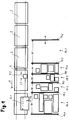
- Fig. 1 shows a schematic plan view of a sorting device with a series of mutually coupled sorting 2, which are movable along a sorting path 4 in a transport direction 6.
- Each sorting trolley is provided with a load receiving device for the controlled picking up and delivery of parcel parts, wherein the in Fig. 1 seen in the transport direction 6 foremost sorting 2.1, 2.2 with different sized parcel parts 8.1, 8.2 are occupied.
- An essential dimension of each piece goods here is its length, as seen in the transport direction 6, in Fig. 1 is denoted by L1 for the parcel item 8.1 and L2 for the parcel item 8.2.
- the load receiving devices of the sorting 2 can be designed as tiltable transversely to the transport direction 6 tilting trays or transversely to the transport direction driven cross belt conveyor, so that a selected piece goods on a selected sorting 2 with appropriate control of the load receiving device, a movement component can be issued transversely to the transport direction 6, whereupon General cargo in the direction of the arrows 10 to a selected terminal 12.1, 12.2, 12.3, 12.4, 12.5 can be passed.
- Fig. 1 a situation is shown in which the parcel item 8.1 is delivered to the terminal 12.1 and the parcel item 8.2 to the terminal 12.3.
- Each terminal 12.1 ... 12.5 represents a sorting destination for piece goods to be sorted, and can be configured differently.
- a terminal can z.
- a terminal may be formed only by a container which serves to receive piece goods.
- Each terminal 12.1 ... 12.5 has a width B1 ... B5, ie seen a dimension in the transport direction 6, wherein at least one terminal in terms of their width during operation of the sorting device is adjustable.
- Fig. 1 explains this on the basis of partitions 14.1, 14.2, ... 14.6, wherein in each case a terminal between two immediately adjacent partitions 14.1, 14.2; 14.2, 14.3, etc. arranged or formed by these. Based on the partition 14.6, the adjustability of the width of the terminal 12.5 is explained, wherein the partition wall 14.6, which is arranged perpendicular to the transport direction 6, in the direction of the transport direction 6 controlled displaced, so that a certain width B5 of the terminal 12.5 is adjustable.
- an inclined inclined surface may be located below the adjustable dividing walls 14.1... 14.6 above which the dividing walls are displaceable so that different widthwise end points in the form of chutes result between adjacent dividing walls.
- each individual partition wall 14.1... 14.6 can be displaceable in the transport direction 6, so that each end point can be adjusted in its width.
- the adjustment of the width to the terminals is carried out by a central controller, which also receives position information of the sorting trolley and with the load receiving device of a selected sorting trolley 2 for delivery a piece of goods on it can be controlled at a selected terminal.
- a central controller which also receives position information of the sorting trolley and with the load receiving device of a selected sorting trolley 2 for delivery a piece of goods on it can be controlled at a selected terminal.
- a particular advantage is that the width of the terminal at which a particular parcel is to be delivered to the length L1, L2 of the relevant parcel item 8.1, 8.2 can be adjusted immediately before delivery.
- the width of the terminal can be adapted to the number, the volume or a base area of the piece goods to be delivered at this terminal.
- one or more additional partitions from an idle position in which the respective partition are arranged away from the sorting path, are brought into an operating position in which they together or in combination with existing end-forming partitions one or more form additional terminals.
- a movement from the rest position into the operating position can either take place in a straight line transversely to the transport direction 6, or in the form of a pivoting movement about a horizontal axis, the partition being arranged in the rest position parallel or oblique to the transport direction 6 and in the operating position transversely to the transport direction 6 can.
- the partitions need not necessarily be arranged transversely to the transport direction 6.
- a longitudinal direction of the end points, which runs parallel to the partitions may be arranged transversely or at an obtuse angle to the transport direction 6, for example between 120 ° and 60 °. If a terminal is formed between two partitions that are not parallel to each other, converging or diverging from the sorting path 4, a longitudinal direction of the end points would be an angle bisector of these bounding partitions.
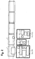
- Fig. 2 shows an embodiment in which terminals of different widths are formed by receptacles 16.1, 16.2, 16.3 different widths B1, B2, B3, wherein the containers are adjustable in width or changeable, as needed during operation of the sorting device.
- the receptacles 16.1... 16.3 can be formed, for example, by flexible boxes whose width can be changed.
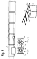
- Fig. 3 shows by way of example three different Widths of the receptacle, wherein a size ratio between the largest and smallest width is about 3.
- the width can usefully be reduced and enlarged so far that it corresponds to the smallest and largest length of piece goods to be sorted, or according to the volume or the base area of the piece goods.
- full or no longer needed containers can be removed. They can either be exchanged or their place remains free.
- Fig. 3 shows a variant of the embodiment according to Fig. 2 wherein flexible receptacles 20 are formed by flexible bags, bags or similar containers with flexible sidewalls.
- Each receptacle or bag 20 is held on a carrier pair 20a, 20b displaceable in the transport direction 6, so that an enlargement or reduction of the width of the receptacle or bag 20 can be achieved by displacement of one or both of the carriers 20a, 20b.
- the carriers 20a, 20b of each receptacle 20 are displaceably guided on a guide rail 22 running parallel to the transport direction 6 and provided with a suitable actuating device for displacement in the transport direction 6.
- a controller not shown, which receives position information of the sorting trolley and with which a load-receiving device of a selected sorting trolley for delivering a piece goods item located thereon can be activated at a selected terminal.
- the width of a respective terminal is the central or decentralized control known and / or adjustable by this, for example, the displacement of the partitions 14.1 ... 14.6, the width adjustment of the receptacle 16.1 ... 16.3 or the movement of the carrier 20a, 20b for width adjustment of a bag 20 by the central control coordinated with the movement of the sorting trolleys and the delivery of parcel parts is executed.
- the width of a terminal is changed manually by an operator.
- Fig. 4a, 4b and 4c show three schematic plan views of each one terminal arrangement of a sorting device, the individual views show a possible temporal evolution of positions and widths of the terminals at three successive times t1 to t3, ie Fig. 4a shows the terminal arrangement of the sorting device to a Time t1, Fig. 4b a possible terminal arrangement at a later time t2 and Fig. 4c a possible terminal arrangement for a later time t3.
- hatched end stations denote terminals which are filled with their receptacles and which are either replaced by a certain number of empty terminals or receptacles of a certain width or remain empty, d. H. an initially existing terminal is removed.
- Fig. 4a to Fig. 4c show that individual terminals remain with unchanged width over a certain time, while other terminals are filled at shorter intervals and then replaced or removed by a terminal with a different width. This provides a higher number of terminals on the same area over time than in the prior art.
Description
- Die Erfindung betrifft eine Sortiervorrichtung mit Sortierwagen, die entlang eines Sortierweges in einer Transportrichtung verfahrbar sind und jeweils mit einer Lastaufnahmeeinrichtung zum gesteuerten Aufnehmen und Abgeben von Stückgutteilen versehen sind, mit einer Anzahl von Endstellen, wobei jede Endstelle in Transportrichtung gesehen eine bestimmte Breite aufweist und an jeder Endstelle Stückgutteile entsprechend eines jeweiligen Sortierziels gezielt von den Sortierwagen abgebbar sind, wie beispielsweise aus
US-A-5,990,437 bekannt, sowie ein Sortierverfahren unter Verwendung einer solchen Sortiervorrichtung. Die Sortierwagen weisen als Lastaufnahmeeinrichtung in der Regel eine Kippschale oder einen Quergurtförderer auf, so dass ein aufgenommenes Stückgutteil quer zur Transportrichtung an einer Endstelle abgegeben werden kann. Bei einer Anzahl von Sortierzielen ist eine entsprechende Anzahl von Endstellen notwendig, wobei jede Endstelle eine ausreichende Breite aufweisen muss, damit auch ein größeres Stückgutteil problemlos übernommen werden kann. Die aus einer größeren Anzahl von Endstellen mit einer gewissen Breite resultierende Gesamtbreite eines Ausschleusbereichs ist häufig problematisch, da nicht immer ausreichend Platz zur Verfügung steht. Man ist daher bestrebt, die Breite des Ausschleusbereichs möglichst gering zu halten, wofür es zweckmäßig ist, die Breite der Endstellen möglichst gering zu halten. Dies bewirkt eine bedarfsgerechte Anzahl an Endstellen über die Zeit und damit einen erhöhten Durchsatz. - Erfindungsgemäß ist vorgesehen, dass die Breite mindestens einer Endstelle im Betrieb der Sortiervorrichtung einstellbar ist und insbesondere an eine Länge eines abzugebenden Stückgutteils anpassbar ist. Man hat nämlich erkannt, dass durch die Anpassung der Breite der Endstellen an die an diesen Endstellen zu übergebenden Stückgutteile dazu führt, dass der Ausschleusbereich insgesamt nicht zu groß wird, bzw. dass sich die benötigte Anzahl von Endstellen innerhalb einer geringeren Gesamtbreite als bisher unterbringen lässt.
- Bevorzugt ist vorgesehen, dass die Breite mindestens einer Endstelle stufenlos oder in vorgegebenen Stufen einstellbar ist.
- Mindestens eine Endstelle kann einen Behälter mit einstellbarer Breite aufweisen. Alternativ oder zusätzlich kann vorgesehen sein, dass mindestens eine Endstelle eine Rutsche mit einstellbarer Breite aufweist. Die Rutsche kann sich je nach Breiteneinstellung in einer von dem Sortierweg wegweisenden Abgaberichtung verengen oder erweitern.
- In einer bevorzugten Weiterbildung der Erfindung ist vorgesehen, dass die Anzahl von Endstellen im Betrieb der Sortiervorrichtung einstellbar ist, wobei je nach Bedarf an Sortierzielen zusätzliche Endstellen einrichtbar oder vorhandene Endstellen entfernbar sind.
- Zweckmäßigerweise ist die Breite einer Endstelle mindestens so groß wie eine Länge, in Transportrichtung gesehen, eines abzugebenden Stückgutteils eingestellt.
- Es können Endstellen mit unterschiedlichen Breiten, angepasst an zu erwartende Längen von abzugebenden Stückgutteilen, einrichtbar sein.
- Zwei benachbarte Endstellen können durch eine bewegbare Trennwand voneinander getrennt sein und jeweils eine weitere seitliche Abgrenzung aufweisen, wobei die Trennwand zwischen den seitlichen Abgrenzungen bewegbar ist, um die Breiten der Endstellen zu verändern oder um eine der beiden Endstellen zu entfernen.
- Unter Endstellen sind sämtliche Vorrichtungen zu verstehen, in denen Stückgutteile aufgenommen werden können, die von einer Sortiervorrichtung ausgeschleust werden. Beispielsweise kann eine Endstelle als Rutsche, Behälter, Rollenbahn oder aktive Fördereinrichtung wie Gurtförderer ausgebildet sein. Ein Sack ist als Sonderform eines Behälters zu verstehen. Einer Sortiervorrichtung können eine einzige Art von Endstellen zugeordnet sein, oder aber mehrere unterschiedliche Endstellenformen.
- Soweit eine Endstelle einen Behälter aufweist, kann dieser durch einen flexiblen Sack gebildet sein, der an in Transportrichtung verschiebbaren Trägern zur Breitenverstellung gehalten ist.
- Es kann vorgesehen sein, dass die Endstellen innerhalb des Ausschleusbereichs in jeder Verstellposition lückenlos benachbart angeordnet sind, oder aber dass die Endstellen in mehreren aus benachbarten Endstellen bestehenden Gruppen angeordnet sind, wobei zwischen den Gruppen Abstände bestehen, in denen keine Endstellen angeordnet sind. Alternativ könnte zwischen je zwei benachbarten Endstellen ein bestimmter Abstand vorgesehen sein.
- Zweckmäßigerweise ist eine zentrale oder dezentrale Steuerung vorgesehen, die Positionsinformationen der Sortierwagen erhält und mit der eine Lastaufnahmeeinrichtung eines ausgewählten Sortierwagens zur Abgabe eines darauf befindlichen Stückgutteils an einer ausgewählten Endstelle ansteuerbar ist. Der Abgabevorgang kann anhand einer Positionsinformation des Sortierwagens ausgelöst werden, indem die Position eines ausgewählten Sortierwagens am Ort der ausgewählten Endstelle erfasst wird. Beispielsweise kann ein Sensor im Bereich der Endstelle ortsfest angeordnet sein, so dass ein vorbeilaufender Sortierwagen erfasst und der Abgabevorgang ausgelöst werden kann. Alternativ kann die Position mindestens eines Sortierwagens erfasst werden, oder die Sortierwagen teilen ihre Position selbstständig mit. Die Positionen der übrigen Sortierwagen werden dementsprechend berechnet. Wird die Position aller Sortierwagen erfasst, erfolgt keine Berechnung. Der Abgabevorgang wird auf der Grundlage dieser vorausgegangenen Positionsbestimmung durchgeführt. In diesem Fall braucht das Eintreffen des Sortierwagens an der Endstelle nicht sensortechnisch erfasst zu werden, was gerade bei variablen Endstellen einen großen Vorteil darstellt.
- Bevorzugt ist vorgesehen, dass die Steuerung Abmessungsinformationen, insbesondere Längeninformationen der Stückgutteile erhält, bspw. über eine Eingabe, eine Längenerfassung oder aus einer Datenbank, und durch die Steuerung aufgrund der Längeninformationen gezielt eine bestimmte Endstelle zur Abgabe auswählbar oder eine ausgewählte Endstelle in ihrer Breite an die Länge eines bestimmten Stückgutteils anpassbar ist. Insbesondere ist ein besonders langes, zwei oder mehr Lastaufnahmeeinrichtungen belegendes Stückgutteil an einer ausgewählten Endstelle mit ausreichender Breite abgebbar, oder eine ausgewählte Endstelle ist für die Annahme eines solchen Stückgutteils in ihrer Breite anpassbar.
- Die Breite der Endstelle ist nicht nur von der Länge der abzugebenden Stückgutteile abhängig, sondern kann auch von der geplanten Anzahl und/oder der Grundfläche oder dem Volumen der Stückgutteile abhängen.
- Es kann weiterhin vorgesehen sein, dass eine Länge mindestens einer Endstelle im Betrieb der Sortiervorrichtung einstellbar ist, wobei die Länge bevorzugt von der zentralen Steuerung eingestellt wird. Bei einer Längenveränderung wird der Abstand zwischen einer Endstelle und dem Sortierweg verkleinert oder vergrößert.
- Die Erfindung bezieht sich weiterhin auf ein Verfahren zum Sortieren von Stückgutteilen, unter Verwendung einer erfindungsgemäßen Sortiervorrichtung, wobei jedem Stückgutteil ein Sortierziel in Form einer bestimmten Endstelle zugeordnet wird und die Breite mindestens einer Endstelle während des Betriebs verändert wird. Es kann vorgesehen sein, dass eine Länge eines bestimmten Stückgutteils erfasst, manuell oder automatisch eingegeben oder einer Datenbank entnommen wird und dass eine Breite einer bestimmten Endstelle an die Länge angepasst wird.
- Ferner kann vorgesehen sein, dass eine bestimmte Anzahl von Endstellen während des Betriebs eingestellt wird. Hierfür können je nach Bedarf an Sortierzielen zusätzliche Endstellen eingerichtet oder vorhandene Endstellen entfernt werden.
- Die Erfindung sieht bevorzugt vor, dass ein Abgabezeitpunkt eines bestimmten Stückgutteils an einer bestimmten Endstelle aus Positionsinformationen des das Stückgutteil transportierenden Sortierwagens bestimmt wird.
- Die Erfindung wird nachfolgend anhand von Ausführungsbeispielen beschrieben, wobei auf eine Zeichnung Bezug genommen wird, in der
-
Fig. 1 eine erste Ausführungsform einer erfindungsgemäßen Sortiervorrichtung zeigt, bei der eine Reihe von Endstellen durch verschiebbare Trennwände gebildet sind, -
Fig. 2 eine zweite Ausführungsform zeigt, bei der Endstellen unterschiedlicher Breite durch Aufnahmebehälter veränderbarer Breite gebildet sind, -
Fig. 3 eine Variante der zweiten Ausführungsform zeigt, bei der die Behälter durch flexible Säcke gebildet sind, und -
Fig. 4a bis c jeweils in einer schematischen Draufsicht auf eine Endstellenanordnung einer Sortiervorrichtung eine mögliche zeitliche Entwicklung von Positionen und Breiten von Endstellen zu drei aufeinanderfolgenden Zeitpunkten t1 bis t3 zeigen. -
Fig. 1 zeigt eine schematische Draufsicht auf eine Sortiervorrichtung mit einer Reihe von untereinander gekoppelten Sortierwagen 2, die entlang eines Sortierwegs 4 in einer Transportrichtung 6 verfahrbar sind. Jeder Sortierwagen ist mit einer Lastaufnahmeeinrichtung zum gesteuerten Aufnehmen und Abgeben von Stückgutteilen versehen, wobei die inFig. 1 in Transportrichtung 6 gesehen vordersten Sortierwagen 2.1, 2.2 mit unterschiedlich großen Stückgutteilen 8.1, 8.2 belegt sind. Eine wesentliche Abmessung jedes Stückgutteils ist hierbei seine Länge, in Transportrichtung 6 gesehen, die inFig. 1 mit L1 für das Stückgutteil 8.1 und L2 für das Stückgutteil 8.2 bezeichnet ist. - Die Lastaufnahmeeinrichtungen der Sortierwagen 2 können als quer zur Transportrichtung 6 kippbare Kippschalen oder als quer zur Transportrichtung antreibbare Quergurtförderer ausgebildet sein, so dass einem ausgewählten Stückgutteil auf einem ausgewählten Sortierwagen 2 bei entsprechender Ansteuerung der Lastaufnahmeeinrichtung eine Bewegungskomponente quer zur Transportrichtung 6 erteilt werden kann, woraufhin das Stückgutteil in Richtung der Pfeile 10 an eine ausgewählte Endstelle 12.1, 12.2, 12.3, 12.4, 12.5 übergeben werden kann.
- In
Fig. 1 ist eine Situation dargestellt, in der das Stückgutteil 8.1 an die Endstelle 12.1 und das Stückgutteil 8.2 an die Endstelle 12.3 abgegeben wird. - Jede Endstelle 12.1 ... 12.5 stellt ein Sortierziel für zu sortierende Stückgutteile dar, und kann unterschiedlich ausgestaltet sein. Eine Endstelle kann z. B.eine Rutsche, Rollenbahn oder aktive Fördereinrichtung wie Gurtförderer aufweisen, wobei am anderen Ende der Rutsche oder Fördereinrichtung eine nachgeschaltete Sortiertechnik oder lediglich ein Aufnahmebehälter angeordnet sein kann.
- Alternativ kann eine Endstelle lediglich durch einen Behälter gebildet sein, der der Aufnahme von Stückgutteilen dient.
- Jede Endstelle 12.1 ... 12.5 weist eine Breite B1 ... B5 auf, d. h. eine Abmessung in Transportrichtung 6 gesehen, wobei zumindest eine Endstelle hinsichtlich ihrer Breite im laufenden Betrieb der Sortiervorrichtung verstellbar ist.
Fig. 1 erläutert dies anhand von Trennwänden 14.1, 14.2, ... 14.6, wobei jeweils eine Endstelle zwischen zwei unmittelbar benachbarten Trennwänden 14.1, 14.2; 14.2, 14.3 usw. angeordnet oder von diesen gebildet ist. Anhand der Trennwand 14.6 ist die Verstellbarkeit der Breite der Endstelle 12.5 erläutert, wobei die Trennwand 14.6, die senkrecht zur Transportrichtung 6 angeordnet ist, in Richtung der Transportrichtung 6 gesteuert verlagerbar ist, so dass eine bestimmte Breite B5 der Endstelle 12.5 einstellbar ist. - Unter den verstellbaren Trennwänden 14.1 ... 14.6 kann sich bspw. eine schräg geneigte Rutschenfläche befinden, oberhalb der die Trennwände verschiebbar sind, so dass sich zwischen benachbarten Trennwänden unterschiedlich breite Endstellen in Form von Rutschen ergeben.
- Insbesondere kann jede einzelne Trennwand 14.1 ... 14.6 in Transportrichtung 6 verschiebbar sein, so dass jede Endstelle in ihrer Breite einstellbar ist.
- Die Einstellung der Breite zu den Endstellen, hier die Verschiebung der einzelnen Trennwände, erfolgt durch eine zentrale Steuerung, die auch Positionsinformationen der Sortierwagen erhält und mit der eine Lastaufnahmeeinrichtung eines ausgewählten Sortierwagens 2 zur Abgabe eines darauf befindlichen Stückgutteils an einer ausgewählten Endstelle ansteuerbar ist. Ein besonderer Vorteil besteht darin, dass die Breite der Endstelle, an der ein bestimmtes Stückgutteil abgegeben werden soll, an die Länge L1, L2 des betreffenden Stückgutteils 8.1, 8.2 unmittelbar vor Abgabe angepasst werden kann. Weithin kann die Breite der Endstelle an die Anzahl, das Volumen oder eine Grundfläche der an dieser Endstelle abzugebenden Stückgutteile angepasst werden.
- Es kann nicht nur die Breite der einzelnen Endstellen verändert werden, sondern es kann auch deren Anzahl während des Betriebs der Sortiervorrichtung vergrößert oder verkleinert werden, wobei entweder Endstellen entfernt oder hinzugefügt werden. Eine beispielhafte Lösung hierfür besteht darin, dass eine oder mehrere zusätzliche Trennwände aus einer Ruhestellung, in der die jeweilige Trennwand entfernt von dem Sortierweg angeordnet sind, in eine Betriebsstellung gebracht werden, in der sie gemeinsam oder im Verbund mit vorhandene Endstellen bildenden Trennwänden eine oder mehrere zusätzliche Endstellen bilden. Eine Bewegung von der Ruhestellung in die Betriebsstellung kann entweder geradlinig quer zur Transportrichtung 6 erfolgen, oder aber in Form einer Schwenkbewegung um eine horizontale Achse, wobei die Trennwand in der Ruhestellung parallel oder schräg zur Transportrichtung 6 und in der Betriebsstellung quer zur Transportrichtung 6 angeordnet sein kann.
- Unabhängig von einer konkreten Ausführungsform müssen die Trennwände nicht zwangsläufig quer zur Transportrichtung 6 angeordnet sein. Mit anderen Worten kann eine Längsrichtung der Endstellen, die parallel zu den Trennwänden verläuft, quer oder unter einem stumpfen Winkel zur Transportrichtung 6 angeordnet sein, bspw. zwischen 120° und 60°. Wenn eine Endstelle zwischen zwei Trennwänden gebildet ist, die nicht parallel zueinander verlaufen, von dem Sortierweg 4 aus gesehen konvergierend oder divergierend, wäre eine Längsrichtung der Endstellen eine Winkelhalbierende der diese begrenzenden Trennwände.
-
Fig. 2 zeigt eine Ausführungsform, bei der Endstellen unterschiedlicher Breite durch Aufnahmebehälter 16.1, 16.2, 16.3 unterschiedlicher Breite B1, B2, B3 gebildet sind, wobei die Behälter in ihrer Breite einstellbar bzw. veränderbar sind, je nach Bedarf im laufenden Betrieb der Sortiervorrichtung. Die Aufnahmebehälter 16.1 ... 16.3 können bspw. durch flexible Kartons gebildet sein, deren Breite sich verändern lässt.Fig. 3 zeigt beispielhaft drei unterschiedliehe Breiten der Aufnahmebehälter, wobei ein Größenverhältnis zwischen größter und kleinster Breite ca. 3 beträgt. In der Praxis kann die Breite sinnvollerweise soweit verkleinert und vergrößert werden, dass sie der kleinsten und größten Länge von zu sortierenden Stückgutteilen entspricht, oder gemäß dem Volumen oder der Grundfläche der Stückgutteile. Weiterhin können volle oder nicht mehr benötigte Behälter abtransportiert werden. Sie können entweder ausgetauscht werden oder ihr Platz bleibt frei. -
Fig. 3 zeigt eine Variante der Ausführungsform gemäßFig. 2 , wobei flexible Aufnahmebehälter 20 durch flexible Säcke, Taschen oder ähnliche Behälter mit flexiblen Seitenwänden gebildet sind. Jeder Aufnahmebehälter bzw. Sack 20 ist an einem in Transportrichtung 6 verschiebbaren Trägerpaar 20a, 20b gehalten, so dass durch eine Verschiebung eines oder beider Träger 20a, 20b eine Vergrößerung oder Verkleinerung der Breite des Aufnahmebehälters bzw. Sacks 20 erreicht werden kann. GemäßFig. 3 sind die Träger 20a, 20b eines jeden Aufnahmebehälters 20 an einer parallel zur Transportrichtung 6 verlaufenden Führungsschiene 22 verlagerbar geführt und mit einer geeigneten Betätigungseinrichtung zur Verschiebung in Transportrichtung 6 versehen. - Bei den beschriebenen Ausführungsformen ist eine nicht dargestellte Steuerung vorgesehen, die Positionsinformationen der Sortierwagen erhält und mit der eine Lastaufnahmeeinrichtung eines ausgewählten Sortierwagens zur Abgabe eines darauf befindlichen Stückgutteils an einer ausgewählten Endstelle ansteuerbar ist. Die Breite einer jeweiligen Endstelle ist der zentralen oder dezentralen Steuerung bekannt und/oder auch von dieser einstellbar, wobei bspw. die Verschiebung der Trennwände 14.1 ... 14.6, die Breitenverstellung der Aufnahmebehälter 16.1 ... 16.3 oder die Bewegung der Träger 20a, 20b zur Breitenverstellung eines Sacks 20 durch die zentrale Steuerung koordiniert mit der Bewegung der Sortierwagen und der Abgabe von Stückgutteilen ausgeführt wird. Weiterhin wäre denkbar, dass die Breite einer Endstelle von einem Bediener manuell verändert wird.
-
Fig. 4a, 4b und 4c zeigen drei schematische Draufsichten auf jeweils eine Endstellenanordnung einer Sortiervorrichtung, wobei die einzelnen Ansichten eine mögliche zeitliche Entwicklung von Positionen und Breiten der Endstellen zu drei aufeinanderfolgenden Zeitpunkten t1 bis t3 zeigen, d. h.Fig. 4a zeigt die Endstellenanordnung der Sortiervorrichtung zu einem Zeitpunkt t1,Fig. 4b eine mögliche Endstellenanordnung zu einem späteren Zeitpunkt t2 undFig. 4c eine mögliche Endstellenanordnung zur einem wiederum späteren Zeitpunkt t3. - In den einzelnen Darstellungen bezeichnen schraffiert dargestellte Endstellen solche Endstellen, die oder deren Aufnahmebehälter mit aufgenommenen Stückgutteilen gefüllt sind und entweder durch eine bestimmte Anzahl leerer Endstellen bzw. Aufnahmebehälter mit einer bestimmten Breite ersetzt werden oder leer bleiben, d. h. eine zunächst bestehende Endstelle wird entfernt.
- Der zeitliche Verlauf von
Fig. 4a zuFig. 4c zeigt, dass einzelne Endstellen über eine gewisse Zeit hin mit unveränderter Breite bestehen bleiben, während andere Endstellen in kürzeren Zeitabständen gefüllt und anschließend durch eine Endstelle mit anderer Breite ersetzt oder entfernt werden. Dadurch wird auf der gleichen Fläche über die Zeit eine höhere Anzahl an Endstellen bereitgestellt als im Stand der Technik. -
- 2
- Sortierwagen
- 4
- Sortierweg
- 6
- Transportrichtung
- 8.1, 8.2
- Stückgutteil
- 12.1 ... 12.5
- Endstelle
- 14.1 ... 14.6
- Trennwand
- 16.1 ... 16.3
- Aufnahmebehälter
- 20
- flexibler Aufnahmebehälter (Sack)
- 20a, 20b
- Träger
- 22
- Führungsschiene
- B1 ... B5
- Breite
- L1, L2
- Länge
- t1, t2, t3
- Zeitpunkt
Claims (17)
- Sortiervorrichtung mit mehreren Sortierwagen (2), die entlang eines Sortierwegs (4) in einer Transportrichtung (6) verfahrbar sind und jeweils mit einer Lastaufnahmeeinrichtung zum gesteuerten Aufnehmen und Abgeben von Stückgutteilen (8.1, 8.2) versehen sind, mit einer Anzahl an Endstellen (12.1 ...12.5), an denen Stückgutteile (8.1, 8.2) entsprechend einem jeweiligen Sortierziel gezielt von den Sortierwagen (2) abgebbar sind, wobei jede Endstelle (12.1 ... 12.5) eine Breite (B1 ... B5) aufweist, dadurch gekennzeichnet, dass die Breite (B1 ... B5) mindestens einiger Endstellen (12.1 ... 12.5) im Betrieb der Sortiervorrichtung einstellbar ist.
- Sortiervorrichtung nach Anspruch 1, dadurch gekennzeichnet, dass Stückgutteile (8.1, 8.2) von einer zentralen oder dezentralen Steuerung entsprechend einem jeweiligen Sortierziel abgebbar sind.
- Sortiervorrichtung nach Anspruch 1 oder 2, dadurch gekennzeichnet, dass die Breite mindestens einer Endstelle (12.1 ... 12.5) stufenlos einstellbar ist.
- Sortiervorrichtung nach einem der Ansprüche 1 bis 3, dadurch gekennzeichnet, dass mindestens eine Endstelle (12.1 ... 12.5) einen Behälter (16.1, 16.2, 16.3) mit einstellbarer Breite aufweist.
- Sortiervorrichtung nach einem der vorangehenden Ansprüche, dadurch gekennzeichnet, dass mindestens eine Endstelle (12.1 ... 12.5) eine Rutsche mit einstellbarer Breite aufweist.
- Sortiervorrichtung nach Anspruch 5, dadurch gekennzeichnet, dass die Rutsche sich je nach Breiteneinstellung in einer von der Sortiervorrichtung wegweisenden Abgaberichtung verengt oder erweitert.
- Sortiervorrichtung nach einem der vorangehenden Ansprüche, dadurch gekennzeichnet, dass die Anzahl von Endstellen (12.1 ... 12.5) im Betrieb der Sortiervorrichtung einstellbar ist, wobei je nach Bedarf an Sortierzielen zusätzliche Endstellen einrichtbar oder vorhandene Endstellen entfernbar sind.
- Sortiervorrichtung nach einem der vorangehenden Ansprüche, dadurch gekennzeichnet, dass die Breite (B1 ... B5) einer Endstelle (12.1 ... 12.5) mindestens so groß wie eine Länge (L1, L2), in Transportrichtung (6) gesehen, eines abzugebenden Stückgutteils (8.1, 8.2) eingestellt ist.
- Sortiervorrichtung nach einem der vorangehenden Ansprüche, dadurch gekennzeichnet, dass mehrere Endstellen (12.1 ... 12.5) mit unterschiedlichen Breiten (B1 ... B5), angepasst an zu erwartende Längen von abzugebenden Stückgutteilen, einrichtbar sind.
- Sortiervorrichtung nach einem der vorangehenden Ansprüche, dadurch gekennzeichnet, dass mehrere Endstellen mit unterschiedlicher Breite, angepasst an zu erwartende Anzahl, Grundfläche und/oder Volumen von abzugebenden Stückgutteilen, einrichtbar sind.
- Sortiervorrichtung nach einem der vorangehenden Ansprüche, dadurch gekennzeichnet, dass zwei benachbarte Endstellen durch eine bewegbare Trennwand (14.1 ... 14.6) voneinander getrennt sind und jeweils eine weitere seitliche Abgrenzung aufweisen, wobei die Trennwand (14.1 ... 14.6) zwischen den seitlichen Abgrenzungen bewegbar ist, um die Breiten der Endstellen zu verändern oder eine der beiden Endstellen zu entfernen.
- Sortiervorrichtung nach einem der Ansprüche 4 bis 11, dadurch gekennzeichnet, dass die Behälter durch flexible Säcke (20) gebildet sind, die an in Transportrichtung (6) verschiebbaren Trägern (20a, 20b) gehalten sind.
- Sortiervorrichtung nach einem der vorangehenden Ansprüche, dadurch gekennzeichnet, dass eine Länge mindestens einer Endstelle im Betrieb der Sortiervorrichtung gesteuert einstellbar ist.
- Verfahren zum Sortieren von Stückgutteilen, unter Verwendung einer Sortiervorrichtung nach einem der Ansprüche 1 bis 13, dadurch gekennzeichnet, dass jedem Stückgutteil (8.1, 8.2) ein Sortierziel in Form einer bestimmten Endstelle (12.1 ... 12.5) zugeordnet wird und die Breite (B1 ... B5) mindestens einer Endstelle (12.1 ... 12.5) während des Betriebs der Sortiervorrichtung verändert wird.
- Verfahren nach Anspruch 14, dadurch gekennzeichnet, dass eine Länge (L1, L2) eines bestimmten Stückgutteils (8.1, 8.2) erfasst, eingegeben oder einer Datenbank entnommen wird und dass eine Breite (B1 ... B5) einer bestimmten Endstelle (12.1 ... 12.5) an die Länge (L1, L2) angepasst wird.
- Verfahren nach Anspruch 14 oder 15, dadurch gekennzeichnet, dass eine vorgebbare Anzahl von Endstellen (12.1 ... 12.5) während des Betriebs der Sortiervorrichtung eingestellt wird.
- Verfahren nach einem der Ansprüche 14 bis 16, dadurch gekennzeichnet, dass ein Abgabezeitpunkt eines bestimmten Stückgutteils (8.1, 8.2) an einer bestimmten Endstelle (12.1 ... 12.5) aus Positionsinformationen des das Stückgutteil (8.1, 8.2) transportierenden Sortierwagens (2) bestimmt wird.
Priority Applications (2)
| Application Number | Priority Date | Filing Date | Title |
|---|---|---|---|
| EP16000404.0A EP3208003B1 (de) | 2016-02-18 | 2016-02-18 | Sortiervorrichtung mit einstellbaren endstellen sowie verfahren unter verwendung einer solchen sortiervorrichtung |
| US15/385,065 US10052662B2 (en) | 2016-02-18 | 2016-12-20 | Sorting device with adjacent terminals |
Applications Claiming Priority (1)
| Application Number | Priority Date | Filing Date | Title |
|---|---|---|---|
| EP16000404.0A EP3208003B1 (de) | 2016-02-18 | 2016-02-18 | Sortiervorrichtung mit einstellbaren endstellen sowie verfahren unter verwendung einer solchen sortiervorrichtung |
Publications (2)
| Publication Number | Publication Date |
|---|---|
| EP3208003A1 EP3208003A1 (de) | 2017-08-23 |
| EP3208003B1 true EP3208003B1 (de) | 2018-04-18 |
Family
ID=55411147
Family Applications (1)
| Application Number | Title | Priority Date | Filing Date |
|---|---|---|---|
| EP16000404.0A Active EP3208003B1 (de) | 2016-02-18 | 2016-02-18 | Sortiervorrichtung mit einstellbaren endstellen sowie verfahren unter verwendung einer solchen sortiervorrichtung |
Country Status (2)
| Country | Link |
|---|---|
| US (1) | US10052662B2 (de) |
| EP (1) | EP3208003B1 (de) |
Families Citing this family (2)
| Publication number | Priority date | Publication date | Assignee | Title |
|---|---|---|---|---|
| US11318499B2 (en) * | 2019-12-19 | 2022-05-03 | Nimble Robotics, Inc. | Robotic system having shuttle |
| CN112918128B (zh) * | 2021-02-03 | 2021-12-17 | 温州职业技术学院 | 一种能自动分拣发票并自动盖章装置 |
Family Cites Families (6)
| Publication number | Priority date | Publication date | Assignee | Title |
|---|---|---|---|---|
| US5990437A (en) * | 1997-02-05 | 1999-11-23 | W & H Systems, Inc. | System for sorting articles |
| DE10145295A1 (de) * | 2001-09-14 | 2003-04-24 | Siemens Dematic Ag | Verfahren zur Verteilreihenfolgesortierung |
| US6736254B1 (en) * | 2002-05-14 | 2004-05-18 | Mantissa Corporation | Off-set block tilt tray sorter with gap detector |
| AU2004237918B2 (en) * | 2004-12-15 | 2007-04-05 | Withcott Group Pty Ltd | Harvesting method and apparatus for leafy vegetables or legumes |
| US20080000817A1 (en) * | 2006-06-30 | 2008-01-03 | Bowe Bell + Howell Company | Sort scheme generation based on bin capacity |
| US10748278B2 (en) * | 2012-06-18 | 2020-08-18 | Sobru Solutions, Inc. | Organism evaluation system and method of use |
-
2016
- 2016-02-18 EP EP16000404.0A patent/EP3208003B1/de active Active
- 2016-12-20 US US15/385,065 patent/US10052662B2/en active Active
Non-Patent Citations (1)
| Title |
|---|
| None * |
Also Published As
| Publication number | Publication date |
|---|---|
| US20170239688A1 (en) | 2017-08-24 |
| EP3208003A1 (de) | 2017-08-23 |
| US10052662B2 (en) | 2018-08-21 |
Similar Documents
| Publication | Publication Date | Title |
|---|---|---|
| EP3254893B1 (de) | Zustellfahrzeug und verfahren zur zustellung von sendungen an unterschiedlichen orten einer zustellroute | |
| EP2315714B1 (de) | Vorrichtung zum vollautomatisierten kommissionieren von artikeln in auftragsladehilfsmittel | |
| AT512338B1 (de) | Kommissionierstation und verfahren zum kommissionieren von artikeln | |
| EP2766285B2 (de) | System und verfahren zum manuellen batch-picken unter anwendung des ware-zum-mann-prinzips | |
| EP0860382B1 (de) | Kommossionierverfahren sowie Kommissionieranlage zur Durchführung des Verfahrens | |
| EP2958838B1 (de) | Vorrichtung und verfahren zum transportieren von gegenständen | |
| EP3228496A2 (de) | Zustellfahrzeug und verfahren zum abliefern von sendungen an unterschiedlichen orten entlang einer zustellroute | |
| AT520281B1 (de) | Hängefördersystem zum Sortieren von Produkten | |
| EP3584197B1 (de) | Lagersystem | |
| EP2102063B1 (de) | Be- und entladen von fluggepäckstücken | |
| DE102008036564A1 (de) | Skalierbarer Versandpuffer mit integrierter Sortierfunktion und Verfahren dazu | |
| EP1686080A2 (de) | Kommissionerplatz und Verfahren zum Kommissionieren | |
| DE4336885A1 (de) | Kommissionierungsanlage für Apothekenprodukte | |
| DE102015111098A1 (de) | Verfahren und Vorrichtung zum Depalettieren von Reifen | |
| AT405640B (de) | Kommissionieranlage | |
| EP0183074B1 (de) | Rechnergesteuerte Kommissionieranlage | |
| WO2014009138A1 (de) | Verfahren und vorrichtung zum transport von gegenständen aus abgebenden stationen in aufnehmende stationen | |
| EP3303153B1 (de) | Verfahren und vorrichtung zum zuführen von produkten in behälter | |
| EP3025971B1 (de) | Füll- und wechselvorrichtung zum befüllen von behältern mit schüttgut | |
| EP3613681A1 (de) | Flächensorter über mindestens zwei ebenen | |
| EP3208003B1 (de) | Sortiervorrichtung mit einstellbaren endstellen sowie verfahren unter verwendung einer solchen sortiervorrichtung | |
| WO2019007544A1 (de) | Banknotenbehälter-bereitstellungssystem | |
| EP2557056A2 (de) | Lagersystem mit Hubbalkengerät | |
| EP0856479A1 (de) | Behälter-Sortierpuffer für eine Kommissionieranlage | |
| DE202016103890U1 (de) | Kommissioniersystem |
Legal Events
| Date | Code | Title | Description |
|---|---|---|---|
| PUAI | Public reference made under article 153(3) epc to a published international application that has entered the european phase |
Free format text: ORIGINAL CODE: 0009012 |
|
| STAA | Information on the status of an ep patent application or granted ep patent |
Free format text: STATUS: THE APPLICATION HAS BEEN PUBLISHED |
|
| STAA | Information on the status of an ep patent application or granted ep patent |
Free format text: STATUS: REQUEST FOR EXAMINATION WAS MADE |
|
| AK | Designated contracting states |
Kind code of ref document: A1 Designated state(s): AL AT BE BG CH CY CZ DE DK EE ES FI FR GB GR HR HU IE IS IT LI LT LU LV MC MK MT NL NO PL PT RO RS SE SI SK SM TR |
|
| AX | Request for extension of the european patent |
Extension state: BA ME |
|
| 17P | Request for examination filed |
Effective date: 20170802 |
|
| RBV | Designated contracting states (corrected) |
Designated state(s): AL AT BE BG CH CY CZ DE DK EE ES FI FR GB GR HR HU IE IS IT LI LT LU LV MC MK MT NL NO PL PT RO RS SE SI SK SM TR |
|
| GRAP | Despatch of communication of intention to grant a patent |
Free format text: ORIGINAL CODE: EPIDOSNIGR1 |
|
| STAA | Information on the status of an ep patent application or granted ep patent |
Free format text: STATUS: GRANT OF PATENT IS INTENDED |
|
| INTG | Intention to grant announced |
Effective date: 20180103 |
|
| GRAS | Grant fee paid |
Free format text: ORIGINAL CODE: EPIDOSNIGR3 |
|
| GRAA | (expected) grant |
Free format text: ORIGINAL CODE: 0009210 |
|
| STAA | Information on the status of an ep patent application or granted ep patent |
Free format text: STATUS: THE PATENT HAS BEEN GRANTED |
|
| AK | Designated contracting states |
Kind code of ref document: B1 Designated state(s): AL AT BE BG CH CY CZ DE DK EE ES FI FR GB GR HR HU IE IS IT LI LT LU LV MC MK MT NL NO PL PT RO RS SE SI SK SM TR |
|
| REG | Reference to a national code |
Ref country code: GB Ref legal event code: FG4D Free format text: NOT ENGLISH |
|
| REG | Reference to a national code |
Ref country code: CH Ref legal event code: EP |
|
| REG | Reference to a national code |
Ref country code: AT Ref legal event code: REF Ref document number: 989877 Country of ref document: AT Kind code of ref document: T Effective date: 20180515 |
|
| REG | Reference to a national code |
Ref country code: IE Ref legal event code: FG4D Free format text: LANGUAGE OF EP DOCUMENT: GERMAN |
|
| REG | Reference to a national code |
Ref country code: DE Ref legal event code: R096 Ref document number: 502016000845 Country of ref document: DE |
|
| REG | Reference to a national code |
Ref country code: DE Ref legal event code: R081 Ref document number: 502016000845 Country of ref document: DE Owner name: BEUMER GROUP GMBH & CO. KG, DE Free format text: FORMER OWNER: BEUMER GMBH & CO. KG, 59269 BECKUM, DE |
|
| RAP2 | Party data changed (patent owner data changed or rights of a patent transferred) |
Owner name: BEUMER GROUP GMBH & CO. KG |
|
| REG | Reference to a national code |
Ref country code: NL Ref legal event code: FP |
|
| REG | Reference to a national code |
Ref country code: LT Ref legal event code: MG4D |
|
| REG | Reference to a national code |
Ref country code: NL Ref legal event code: HC Owner name: BEUMER GROUP GMBH & CO. KG; DE Free format text: DETAILS ASSIGNMENT: CHANGE OF OWNER(S), CHANGE OF OWNER(S) NAME; FORMER OWNER NAME: BEUMER GMBH & CO. KG Effective date: 20180718 |
|
| PG25 | Lapsed in a contracting state [announced via postgrant information from national office to epo] |
Ref country code: FI Free format text: LAPSE BECAUSE OF FAILURE TO SUBMIT A TRANSLATION OF THE DESCRIPTION OR TO PAY THE FEE WITHIN THE PRESCRIBED TIME-LIMIT Effective date: 20180418 Ref country code: BG Free format text: LAPSE BECAUSE OF FAILURE TO SUBMIT A TRANSLATION OF THE DESCRIPTION OR TO PAY THE FEE WITHIN THE PRESCRIBED TIME-LIMIT Effective date: 20180718 Ref country code: NO Free format text: LAPSE BECAUSE OF FAILURE TO SUBMIT A TRANSLATION OF THE DESCRIPTION OR TO PAY THE FEE WITHIN THE PRESCRIBED TIME-LIMIT Effective date: 20180718 Ref country code: PL Free format text: LAPSE BECAUSE OF FAILURE TO SUBMIT A TRANSLATION OF THE DESCRIPTION OR TO PAY THE FEE WITHIN THE PRESCRIBED TIME-LIMIT Effective date: 20180418 Ref country code: SE Free format text: LAPSE BECAUSE OF FAILURE TO SUBMIT A TRANSLATION OF THE DESCRIPTION OR TO PAY THE FEE WITHIN THE PRESCRIBED TIME-LIMIT Effective date: 20180418 Ref country code: AL Free format text: LAPSE BECAUSE OF FAILURE TO SUBMIT A TRANSLATION OF THE DESCRIPTION OR TO PAY THE FEE WITHIN THE PRESCRIBED TIME-LIMIT Effective date: 20180418 Ref country code: LT Free format text: LAPSE BECAUSE OF FAILURE TO SUBMIT A TRANSLATION OF THE DESCRIPTION OR TO PAY THE FEE WITHIN THE PRESCRIBED TIME-LIMIT Effective date: 20180418 |
|
| PG25 | Lapsed in a contracting state [announced via postgrant information from national office to epo] |
Ref country code: LV Free format text: LAPSE BECAUSE OF FAILURE TO SUBMIT A TRANSLATION OF THE DESCRIPTION OR TO PAY THE FEE WITHIN THE PRESCRIBED TIME-LIMIT Effective date: 20180418 Ref country code: HR Free format text: LAPSE BECAUSE OF FAILURE TO SUBMIT A TRANSLATION OF THE DESCRIPTION OR TO PAY THE FEE WITHIN THE PRESCRIBED TIME-LIMIT Effective date: 20180418 Ref country code: GR Free format text: LAPSE BECAUSE OF FAILURE TO SUBMIT A TRANSLATION OF THE DESCRIPTION OR TO PAY THE FEE WITHIN THE PRESCRIBED TIME-LIMIT Effective date: 20180719 Ref country code: RS Free format text: LAPSE BECAUSE OF FAILURE TO SUBMIT A TRANSLATION OF THE DESCRIPTION OR TO PAY THE FEE WITHIN THE PRESCRIBED TIME-LIMIT Effective date: 20180418 |
|
| PG25 | Lapsed in a contracting state [announced via postgrant information from national office to epo] |
Ref country code: PT Free format text: LAPSE BECAUSE OF FAILURE TO SUBMIT A TRANSLATION OF THE DESCRIPTION OR TO PAY THE FEE WITHIN THE PRESCRIBED TIME-LIMIT Effective date: 20180820 |
|
| REG | Reference to a national code |
Ref country code: DE Ref legal event code: R097 Ref document number: 502016000845 Country of ref document: DE |
|
| PG25 | Lapsed in a contracting state [announced via postgrant information from national office to epo] |
Ref country code: DK Free format text: LAPSE BECAUSE OF FAILURE TO SUBMIT A TRANSLATION OF THE DESCRIPTION OR TO PAY THE FEE WITHIN THE PRESCRIBED TIME-LIMIT Effective date: 20180418 Ref country code: RO Free format text: LAPSE BECAUSE OF FAILURE TO SUBMIT A TRANSLATION OF THE DESCRIPTION OR TO PAY THE FEE WITHIN THE PRESCRIBED TIME-LIMIT Effective date: 20180418 Ref country code: EE Free format text: LAPSE BECAUSE OF FAILURE TO SUBMIT A TRANSLATION OF THE DESCRIPTION OR TO PAY THE FEE WITHIN THE PRESCRIBED TIME-LIMIT Effective date: 20180418 Ref country code: CZ Free format text: LAPSE BECAUSE OF FAILURE TO SUBMIT A TRANSLATION OF THE DESCRIPTION OR TO PAY THE FEE WITHIN THE PRESCRIBED TIME-LIMIT Effective date: 20180418 Ref country code: SK Free format text: LAPSE BECAUSE OF FAILURE TO SUBMIT A TRANSLATION OF THE DESCRIPTION OR TO PAY THE FEE WITHIN THE PRESCRIBED TIME-LIMIT Effective date: 20180418 |
|
| PLBE | No opposition filed within time limit |
Free format text: ORIGINAL CODE: 0009261 |
|
| STAA | Information on the status of an ep patent application or granted ep patent |
Free format text: STATUS: NO OPPOSITION FILED WITHIN TIME LIMIT |
|
| PG25 | Lapsed in a contracting state [announced via postgrant information from national office to epo] |
Ref country code: SM Free format text: LAPSE BECAUSE OF FAILURE TO SUBMIT A TRANSLATION OF THE DESCRIPTION OR TO PAY THE FEE WITHIN THE PRESCRIBED TIME-LIMIT Effective date: 20180418 |
|
| 26N | No opposition filed |
Effective date: 20190121 |
|
| PG25 | Lapsed in a contracting state [announced via postgrant information from national office to epo] |
Ref country code: ES Free format text: LAPSE BECAUSE OF FAILURE TO SUBMIT A TRANSLATION OF THE DESCRIPTION OR TO PAY THE FEE WITHIN THE PRESCRIBED TIME-LIMIT Effective date: 20180418 |
|
| REG | Reference to a national code |
Ref country code: CH Ref legal event code: PL |
|
| PG25 | Lapsed in a contracting state [announced via postgrant information from national office to epo] |
Ref country code: LU Free format text: LAPSE BECAUSE OF NON-PAYMENT OF DUE FEES Effective date: 20190218 Ref country code: MC Free format text: LAPSE BECAUSE OF FAILURE TO SUBMIT A TRANSLATION OF THE DESCRIPTION OR TO PAY THE FEE WITHIN THE PRESCRIBED TIME-LIMIT Effective date: 20180418 |
|
| REG | Reference to a national code |
Ref country code: BE Ref legal event code: MM Effective date: 20190228 |
|
| REG | Reference to a national code |
Ref country code: IE Ref legal event code: MM4A |
|
| PG25 | Lapsed in a contracting state [announced via postgrant information from national office to epo] |
Ref country code: CH Free format text: LAPSE BECAUSE OF NON-PAYMENT OF DUE FEES Effective date: 20190228 Ref country code: LI Free format text: LAPSE BECAUSE OF NON-PAYMENT OF DUE FEES Effective date: 20190228 |
|
| PG25 | Lapsed in a contracting state [announced via postgrant information from national office to epo] |
Ref country code: IE Free format text: LAPSE BECAUSE OF NON-PAYMENT OF DUE FEES Effective date: 20190218 |
|
| PG25 | Lapsed in a contracting state [announced via postgrant information from national office to epo] |
Ref country code: BE Free format text: LAPSE BECAUSE OF NON-PAYMENT OF DUE FEES Effective date: 20190228 |
|
| PG25 | Lapsed in a contracting state [announced via postgrant information from national office to epo] |
Ref country code: TR Free format text: LAPSE BECAUSE OF FAILURE TO SUBMIT A TRANSLATION OF THE DESCRIPTION OR TO PAY THE FEE WITHIN THE PRESCRIBED TIME-LIMIT Effective date: 20180418 |
|
| PG25 | Lapsed in a contracting state [announced via postgrant information from national office to epo] |
Ref country code: MT Free format text: LAPSE BECAUSE OF FAILURE TO SUBMIT A TRANSLATION OF THE DESCRIPTION OR TO PAY THE FEE WITHIN THE PRESCRIBED TIME-LIMIT Effective date: 20180418 |
|
| PG25 | Lapsed in a contracting state [announced via postgrant information from national office to epo] |
Ref country code: CY Free format text: LAPSE BECAUSE OF FAILURE TO SUBMIT A TRANSLATION OF THE DESCRIPTION OR TO PAY THE FEE WITHIN THE PRESCRIBED TIME-LIMIT Effective date: 20180418 |
|
| PG25 | Lapsed in a contracting state [announced via postgrant information from national office to epo] |
Ref country code: IS Free format text: LAPSE BECAUSE OF FAILURE TO SUBMIT A TRANSLATION OF THE DESCRIPTION OR TO PAY THE FEE WITHIN THE PRESCRIBED TIME-LIMIT Effective date: 20180818 |
|
| PG25 | Lapsed in a contracting state [announced via postgrant information from national office to epo] |
Ref country code: HU Free format text: LAPSE BECAUSE OF FAILURE TO SUBMIT A TRANSLATION OF THE DESCRIPTION OR TO PAY THE FEE WITHIN THE PRESCRIBED TIME-LIMIT; INVALID AB INITIO Effective date: 20160218 |
|
| PG25 | Lapsed in a contracting state [announced via postgrant information from national office to epo] |
Ref country code: SI Free format text: LAPSE BECAUSE OF FAILURE TO SUBMIT A TRANSLATION OF THE DESCRIPTION OR TO PAY THE FEE WITHIN THE PRESCRIBED TIME-LIMIT Effective date: 20180418 |
|
| REG | Reference to a national code |
Ref country code: AT Ref legal event code: MM01 Ref document number: 989877 Country of ref document: AT Kind code of ref document: T Effective date: 20210218 |
|
| PG25 | Lapsed in a contracting state [announced via postgrant information from national office to epo] |
Ref country code: AT Free format text: LAPSE BECAUSE OF NON-PAYMENT OF DUE FEES Effective date: 20210218 |
|
| PG25 | Lapsed in a contracting state [announced via postgrant information from national office to epo] |
Ref country code: MK Free format text: LAPSE BECAUSE OF FAILURE TO SUBMIT A TRANSLATION OF THE DESCRIPTION OR TO PAY THE FEE WITHIN THE PRESCRIBED TIME-LIMIT Effective date: 20180418 |
|
| PGFP | Annual fee paid to national office [announced via postgrant information from national office to epo] |
Ref country code: NL Payment date: 20230220 Year of fee payment: 8 |
|
| PGFP | Annual fee paid to national office [announced via postgrant information from national office to epo] |
Ref country code: FR Payment date: 20230217 Year of fee payment: 8 |
|
| PGFP | Annual fee paid to national office [announced via postgrant information from national office to epo] |
Ref country code: IT Payment date: 20230228 Year of fee payment: 8 Ref country code: GB Payment date: 20230221 Year of fee payment: 8 Ref country code: DE Payment date: 20230216 Year of fee payment: 8 |
|
| P01 | Opt-out of the competence of the unified patent court (upc) registered |
Effective date: 20230411 |