EP3674591A1 - Water pipe splitting saddle - Google Patents
Water pipe splitting saddle Download PDFInfo
- Publication number
- EP3674591A1 EP3674591A1 EP19192846.4A EP19192846A EP3674591A1 EP 3674591 A1 EP3674591 A1 EP 3674591A1 EP 19192846 A EP19192846 A EP 19192846A EP 3674591 A1 EP3674591 A1 EP 3674591A1
- Authority
- EP
- European Patent Office
- Prior art keywords
- top portion
- clamping device
- water pipe
- saddle clamping
- saddle
- Prior art date
- Legal status (The legal status is an assumption and is not a legal conclusion. Google has not performed a legal analysis and makes no representation as to the accuracy of the status listed.)
- Withdrawn
Links
- XLYOFNOQVPJJNP-UHFFFAOYSA-N water Substances O XLYOFNOQVPJJNP-UHFFFAOYSA-N 0.000 title claims abstract description 66
- 238000007789 sealing Methods 0.000 claims description 26
- 238000005553 drilling Methods 0.000 claims description 13
- 230000007704 transition Effects 0.000 claims description 2
- 238000009434 installation Methods 0.000 description 4
- 230000002262 irrigation Effects 0.000 description 3
- 238000003973 irrigation Methods 0.000 description 3
- 239000000463 material Substances 0.000 description 3
- 238000010586 diagram Methods 0.000 description 2
- 238000006073 displacement reaction Methods 0.000 description 1
- 239000003651 drinking water Substances 0.000 description 1
- 235000020188 drinking water Nutrition 0.000 description 1
- 239000013013 elastic material Substances 0.000 description 1
- 238000011900 installation process Methods 0.000 description 1
- 239000002184 metal Substances 0.000 description 1
- 238000012986 modification Methods 0.000 description 1
- 230000004048 modification Effects 0.000 description 1
- 238000003825 pressing Methods 0.000 description 1
- 229920002994 synthetic fiber Polymers 0.000 description 1
Images


Classifications
-
- F—MECHANICAL ENGINEERING; LIGHTING; HEATING; WEAPONS; BLASTING
- F16—ENGINEERING ELEMENTS AND UNITS; GENERAL MEASURES FOR PRODUCING AND MAINTAINING EFFECTIVE FUNCTIONING OF MACHINES OR INSTALLATIONS; THERMAL INSULATION IN GENERAL
- F16L—PIPES; JOINTS OR FITTINGS FOR PIPES; SUPPORTS FOR PIPES, CABLES OR PROTECTIVE TUBING; MEANS FOR THERMAL INSULATION IN GENERAL
- F16L41/00—Branching pipes; Joining pipes to walls
- F16L41/08—Joining pipes to walls or pipes, the joined pipe axis being perpendicular to the plane of a wall or to the axis of another pipe
- F16L41/12—Joining pipes to walls or pipes, the joined pipe axis being perpendicular to the plane of a wall or to the axis of another pipe using attaching means embracing the pipe
-
- F—MECHANICAL ENGINEERING; LIGHTING; HEATING; WEAPONS; BLASTING
- F16—ENGINEERING ELEMENTS AND UNITS; GENERAL MEASURES FOR PRODUCING AND MAINTAINING EFFECTIVE FUNCTIONING OF MACHINES OR INSTALLATIONS; THERMAL INSULATION IN GENERAL
- F16L—PIPES; JOINTS OR FITTINGS FOR PIPES; SUPPORTS FOR PIPES, CABLES OR PROTECTIVE TUBING; MEANS FOR THERMAL INSULATION IN GENERAL
- F16L47/00—Connecting arrangements or other fittings specially adapted to be made of plastics or to be used with pipes made of plastics
- F16L47/26—Connecting arrangements or other fittings specially adapted to be made of plastics or to be used with pipes made of plastics for branching pipes; for joining pipes to walls; Adaptors therefor
- F16L47/28—Joining pipes to walls or to other pipes, the axis of the joined pipe being perpendicular to the wall or to the axis of the other pipe
- F16L47/30—Joining pipes to walls or to other pipes, the axis of the joined pipe being perpendicular to the wall or to the axis of the other pipe using attaching means embracing the pipe
Definitions
- the present invention relates to a flow dividing device for water pipe shunting in an irrigation system or drinking water system or in fire extinguishing systems, and in particular to a saddle clamping device for water pipe shunting, the clamping device being installed around a water pipe for water from a main water pipe leaded out.
- the present invention provides a saddle clamping device for water pipe shunting, which connects between the main water pipe and the diverting pipe to facilitate the splitting of water from the main water pipe.
- the saddle clamping device for water pipe shunting comprises:
- the connecting device includes a shaft and a through hole.
- the through hole is formed on both top and bottom portions in such way that a continuous hole is formed when assembling them together.
- the shaft being disposed at a pre-joining end of a top portion/bottom portion of the saddle clamping device, passes the through hole being provided at a pre-joining end of the bottom portion/top portion.
- the bottom portion and the top portion are coupled together by a shaft passing through the hole to enable the saddle clamping device to affect a transition between an open state and a closed state.
- the bottom portion, the top portion, and the connecting device are integrally formed as monolithic part.
- the material formed between the top and bottom portions acts as a hinge, allowing relative movement between the parts, and allows rotating them to form a closed cylindrical space around the pipe.
- the bottom portion or the top portion has an inwardly projecting hook, and the opposite portion is provided with a hole matching the hook at a corresponding position, when the saddle portions is rotated and the hooks are positioned within the aperture when the top portion is closed around the conduit.
- the locking device comprises a bolt and a nut, and the bolt is located in the positioning hole and the semi-opening groove/fixing hole that cooperates with the nut.
- the bolt, the nut, the positioning hole and the semi-opening groove/fixing hole are arranged to tighten the top portion and the bottom portion together, the bolt is freely movable within an angular range between the vertical position and the inclined position.
- the bolt and the nut are inclined between two or more predetermined positions.
- the present invention also provides a locking device comprising pre-installed bolts and nuts that are freely movable within an angular range between a vertical position and a tilted position in a saddle clamping device.
- the pre-installed bolts and nuts are angled between two or more predetermined positions.
- the saddle clamping device for water pipe shunting further comprises a sealing member and a fixing member.
- the fixing member is provided with buckles/snaps that protrude upwards at the outskirts area of the inner surface of the top portion and match grooves at the inner surface.
- the inner surface of the top portion comprises a recess for introducing the sealing member, where the grooves for the buckles/snaps surround the recess of the sealing member in close proximity.
- the present invention also provides fixing means for fixing a drilling device, wherein the fixing means is located at a top portion of the saddle clamping device for aligning and mechanically securing a drilling device to the top surface of the top portion.
- the fixing means allows a drilling device to be securely connected above the female threaded extension, for drilling the main water pipe.
- the drilling device securing means is a plurality of pins, extending out of the top portion and located around the female thread on the top portion.
- the present invention provides a saddle clamping device, wherein a top portion of the saddle clamping device is provided with a female thread, and a lower end of the female thread is provided with a tapered inclined surface for improving the introduction into the threaded hole, and the sealing of the male thread equipment.
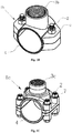
- Figs. 1A-1C show a schematic, structural view of a preferred embodiment of a conventional saddle clamping device 1a-1c in a fully closed position (a conduit is not shown).
- the top and bottom portions of the saddle clamping device are mechanically coupled by bolts 2 and nuts 7 to form a cylindrical space 4 for clamping around the water tube.
- the top portion of the saddle clamping device 1a-1c is designed with a hollow cylindrical hole 3a-3c having a female thread.
- the hollow cylindrical hole 3a-3c having a female thread is positioned during assembly over a hole in the primary water main pipe and then a stage splitter pipe is connected to the hole.
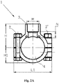
- Figs. 2A to 2B show a front view and a side view of a conventional saddle clamping device 1 in its fully closed position.
- the schematic shows the geometrical diameters of the top and bottom sides of the saddle clamping device along the vertical and parallel directions of the main water pipe, the saddle clamping device comprising a female threaded portion 3 at the top.
- the schematic corresponds to a conventional saddle clamping device, which is made of two separate parts and secured by two bolts 2 , 2' on each side of the saddle.
- Fig. 3 is a schematic exploded view of a conventional saddle clamping device including a saddle top portion 1b' and a bottom portion 1a' clamped around the pipe to be shunt for sealing the holes in the main water pipe member.
- O-ring 8' is used for sealing the area around the drilled hole in the main water pipe, for preventing leakage of water.
- Bolt 2 and nut 7 are used to close and secure the saddle clamping device around the water pipe to be diverted.
- Fig. 4 shows all the components of the saddle clamping device 1 installed around the primary water main pipe 12 and the secondary two-way water pipe 13 to be branched.
- the secondary water distribution pipe is connected to the corresponding female screw portion 3 through the corresponding adapter 14 .
- Fig. 5A shows a typical installation procedure of conventional saddle clamping device, during which the bolts 2 should be screwed one after the other in order to secure the saddle clamping device parts 1 around the water pipe 12 .
- Fig. 5B show a state diagram of an assembly of a water pipe 12 having a conventional saddle clamping device 1 during drilling, with a manual electric drill device at the top side of the primary water pipe 12 to be split. The inside of the hollow cylindrical hole 3a (shown in Fig. 5A ) having a female thread is bored.
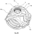
- Fig. 6A to Fig. 6C are schematic views showing the inner and outer structures of one of the preferred designs of the saddle clamping device in the fully open state and the fully closed state of the present invention.
- the top and bottom portions are joined at the pre-joined end 16 by a hinge, this side being labelled as a pre-joined side.
- the free end, the bottom portion and the top portion comprise various mechanical locking means.
- a locating hole is formed at the free end of the bottom portion.
- the bolt 2 is embedded in the locating hole and a nut 7 is matched with the thread.
- the top portion includes matching semi-opening slot/fixing hole 15 .
- the figure shows the bolt tilting structure, including the bolt 2 in an inclined position in the open state of the saddle clamping device.
- the bolt 2 is switched from the tilt to the vertical position inside the half opening slot/fixing hole 15.
- the top and bottom portions can be brought to a fully closed state around the water tube (not shown) along the axis provided by the hinge.
- Fig. 6D shows another configuration, in which the locking device comprises two bolts 2' and 2" and corresponding nuts 7' and 7" are positioned in two adjacent locating holes at the free end of the bottom portion of the saddle clamping device.
- Corresponding locating/fixing semi-open slots 15' and 15" are located parallel to the bolts 2' and 2" at the free end of the top portion of the saddle clamping device. Such configuration further tightens the hold of saddle to the pipe and improves securing it in place.
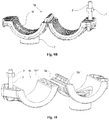
- Fig. 7A and Fig. 7B are schematic views showing the structure of the two alternative designs 1d-1e of the saddle clamping device in an open state.
- the top and bottom of the saddle clamping device are connected by a shaft 5d which passes thru a both top and bottom portions holding them together as shown in Fig. 7A or by an integrally injected joint/axis 5e as shown in Fig. 7B .
- the saddle clamping device can be fabricated from a sturdy synthetic material similar to the design shown in Fig. 7B .
- the saddle clamping device can also be constructed from two separate pieces that are held together by a metal hinge or plastic hinge going through a shaft hole as shown in Fig. 7A .
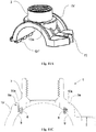
- Fig. 8A to Fig. 8C show the installation process of the saddle clamping device 1e around the primary water main pipe (not shown).
- the configuration includes at least one bolt 2 structure that tilts the fixing bolts and at least one fixing nut 7 to mount the clamping device around the main water pipe.
- Fig. 8A shows the saddle clamping device 1e in a partially closed state during installation, with the bolt 2 in an unlocked, tilted position and pushed away from the top portion of the saddle so that the top portion can be closed over the water pipe.
- Fig. 8B shows the saddle clamping device in a fully closed state during installation, while the bolt 2 is still in its tilted, unlocked position.
- FIG. 8B shows that the top portion of the saddle clamping device further includes additional four pin members 6a-6d positioned along the periphery of the female threaded portion 3 at the top portion 1b . These four pins are used to align and mechanically mount the drilling device within the female threaded portion 3 to form a hole in the top of the main water pipe for connecting the split water pipe.
- Fig. 8C shows the saddle clamping device in a fully closed state with the bolt locked in a vertical position with the corresponding nut.
- Figs. 9A through 9B show two configurations of a saddle clamping device having a bolt in a pre-installed state.
- the bolts 2 and nuts 7 are in an inclined position ( Fig. 9A ) and a vertical position ( Fig. 9B ), respectively.
- These two configurations illustrate a mechanical device for securing the various portions of the saddle clamping device together.
- the figures show the advantages offered by the tilt bolts in terms of freedom and locking.
- the two extreme positions of the nut and bolt shown in Fig. 9A and Fig. 9B can be either discrete and pre-determined or such that the bolt is free to move in a plurality of angles within a defined range.
- Fig. 10 shows a particular embodiment of a saddle clamping device 1h secured by two mechanical means on either side of the saddle, having a bolt 2 and a hook and hole system 5h' and 5h" correspondingly.
- the top and bottom of the saddle clamping device are connected by a flexible intermediate shaft 5e .
- the hook 5h' at the connecting end of the top portion of the saddle 1h protrudes outwardly and locks inside the corresponding hole 5h" at the connecting end of the bottom portion of the saddle. This way of locking the hook in the hole is assembled an additional mechanical holding forces can then be generated.
- Figs. 11A-11B illustrate a top portion of a saddle clamping device having a seal 8 and a seal securing and fixing member 9 .
- the seal fixing member 9 holds the seal 8 in place so as not to affect the tightness of the seal area.
- the seal 8 is placed in a recess at the inner surface of the top portion, where the recess encircles the circumference of the entry of the female thread into the top portion 1b' .
- the fixing member 9 is placed on top of it and locked to the inner surface of the top portion with buckles 9a for preventing the seal from coming off of the body of the saddle during handling or when assembled on the pipe.
- the buckles are introduced into and locked in corresponding, matching grooves that surround the recess that houses the seal 8 .
- the outer walls of these grooves are illustrated as 10a in Fig. 11B .
- Fig. 11C illustrates cross-section of top portion 1b' and shows the relative locations of the seal 8 in its recess, the fixing member 9 on top of it and the buckles 9a that extend from the fixing member and locked in their corresponding grooves 10a at the outer surface of the top portion.
- the fixing member 9 with buckles 9a locks the seal between the fixing member 9 and the inner surface of the top portion. This ensures the seal 8 will properly seal an opening, which is drilled into a pipe on which the saddle clamping device is mounted, through the entry of the female thread.
- the seal 8 is preferably made of elastic material with sufficient thickness to form proper seal for the water that flows out of the main pipe through the female thread.
- the fixing member 9 and its buckles 9a are preferably made of a rigid material to tighten the seal 8 inside the recess and cause a firm grip of buckles 9a in their grooves.
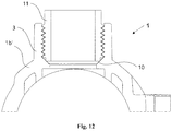
- Fig. 12 shows the saddle clamping device 1 having a bore and a female threaded portion 3 with a tapered bevel 10 on the underside (end) of the female threaded portion 3 .
- the tapered bevel 10 creates a tight seal between the body of the saddle clamping device 1 and a male threaded member 11 screwed into the female threaded portion 3 so that the material can be wrapped or sealed with little or no additional seal to improve the impervious seal.
- This product is to allow water to be separated from the primary water main pipe to the secondary side piping, when designing irrigation structures for fields.
Landscapes
- Engineering & Computer Science (AREA)
- General Engineering & Computer Science (AREA)
- Mechanical Engineering (AREA)
- Branch Pipes, Bends, And The Like (AREA)
- Perforating, Stamping-Out Or Severing By Means Other Than Cutting (AREA)
Applications Claiming Priority (1)
| Application Number | Priority Date | Filing Date | Title |
|---|---|---|---|
| US201862723545P | 2018-08-28 | 2018-08-28 |
Publications (1)
| Publication Number | Publication Date |
|---|---|
| EP3674591A1 true EP3674591A1 (en) | 2020-07-01 |
Family
ID=67704484
Family Applications (1)
| Application Number | Title | Priority Date | Filing Date |
|---|---|---|---|
| EP19192846.4A Withdrawn EP3674591A1 (en) | 2018-08-28 | 2019-08-21 | Water pipe splitting saddle |
Country Status (3)
| Country | Link |
|---|---|
| EP (1) | EP3674591A1 (he) |
| CN (1) | CN209781987U (he) |
| IL (1) | IL268845B2 (he) |
Families Citing this family (1)
| Publication number | Priority date | Publication date | Assignee | Title |
|---|---|---|---|---|
| CN113028182A (zh) * | 2021-03-04 | 2021-06-25 | 吉林建筑大学 | 一种流域污染治理用管道连接结构及其连接方法 |
Citations (6)
| Publication number | Priority date | Publication date | Assignee | Title |
|---|---|---|---|---|
| US2933126A (en) * | 1955-10-05 | 1960-04-19 | Mueller Co | Plastic pipe clamp |
| US3471176A (en) * | 1968-06-10 | 1969-10-07 | Vega Manuf | Tapping saddle |
| US3987276A (en) * | 1974-05-10 | 1976-10-19 | Georg Fischer Aktiengesellschaft | Welded plastic attachment subassembly |
| US3999785A (en) * | 1974-11-18 | 1976-12-28 | Victaulic Company Of Canada, Ltd. | Mechanical pipe outlet |
| US4258941A (en) * | 1979-07-19 | 1981-03-31 | Mueller Co. | Service clamp for plastic pipe or the like |
| DE102011085649A1 (de) * | 2010-11-18 | 2012-05-24 | Schaeffler Technologies Gmbh & Co. Kg | Hydraulisches System |
-
2018
- 2018-12-30 CN CN201822262417.1U patent/CN209781987U/zh active Active
-
2019
- 2019-08-21 EP EP19192846.4A patent/EP3674591A1/en not_active Withdrawn
- 2019-08-22 IL IL268845A patent/IL268845B2/he unknown
Patent Citations (6)
| Publication number | Priority date | Publication date | Assignee | Title |
|---|---|---|---|---|
| US2933126A (en) * | 1955-10-05 | 1960-04-19 | Mueller Co | Plastic pipe clamp |
| US3471176A (en) * | 1968-06-10 | 1969-10-07 | Vega Manuf | Tapping saddle |
| US3987276A (en) * | 1974-05-10 | 1976-10-19 | Georg Fischer Aktiengesellschaft | Welded plastic attachment subassembly |
| US3999785A (en) * | 1974-11-18 | 1976-12-28 | Victaulic Company Of Canada, Ltd. | Mechanical pipe outlet |
| US4258941A (en) * | 1979-07-19 | 1981-03-31 | Mueller Co. | Service clamp for plastic pipe or the like |
| DE102011085649A1 (de) * | 2010-11-18 | 2012-05-24 | Schaeffler Technologies Gmbh & Co. Kg | Hydraulisches System |
Also Published As
| Publication number | Publication date |
|---|---|
| IL268845B2 (he) | 2023-05-01 |
| IL268845A (he) | 2019-10-31 |
| IL268845B1 (he) | 2023-01-01 |
| CN209781987U (zh) | 2019-12-13 |
Similar Documents
| Publication | Publication Date | Title |
|---|---|---|
| US9700909B2 (en) | Shower arm attachment assembly | |
| US8616588B2 (en) | Pipe coupling for connecting two pipe ends | |
| KR102396725B1 (ko) | 파이프 피스를 결합하는 방법 및 결합 공정을 위한 센터링 장치 | |
| EP3674591A1 (en) | Water pipe splitting saddle | |
| US4497511A (en) | Connectors for vessels or pipes | |
| US20110089688A1 (en) | Thread-lockable pipe coupling assembly | |
| KR101519382B1 (ko) | 배관 피팅용 풀림 방지구 | |
| KR200245809Y1 (ko) | 배관라인의 파이프연결용 지그 | |
| CA1324629C (en) | Clamp connector | |
| JP7162463B2 (ja) | 分岐金具 | |
| EP1834123B1 (en) | Flange | |
| KR940011859B1 (ko) | 분기 파이프 이음새 | |
| CA2272452C (en) | Device for holding a pipe on a branch connector | |
| JP3304075B2 (ja) | 混合水栓用の継手 | |
| JPH0529297Y2 (he) | ||
| JP6754660B2 (ja) | 分岐継手 | |
| JP6533154B2 (ja) | 蛇口接続継手 | |
| US11435012B2 (en) | Elbow screw joint system | |
| JP7553053B2 (ja) | アンカー工又はロックボルト工における定着材注入ホースの接続治具 | |
| US20240254784A1 (en) | Clamp assembly for scaffolding | |
| KR102188307B1 (ko) | 시공용이한 오배수용 플라스틱 사출이음관의 원터치 결합구조 | |
| JPH1136392A (ja) | 湯水混合水栓の接続構造 | |
| EP0266296A1 (en) | Arrangement for fastening feed pipes to sanitary fittings | |
| KR200274883Y1 (ko) | 이음관 | |
| JPH1060963A (ja) | 水栓取付用アダプタの固定構造 |
Legal Events
| Date | Code | Title | Description |
|---|---|---|---|
| PUAI | Public reference made under article 153(3) epc to a published international application that has entered the european phase |
Free format text: ORIGINAL CODE: 0009012 |
|
| STAA | Information on the status of an ep patent application or granted ep patent |
Free format text: STATUS: THE APPLICATION HAS BEEN PUBLISHED |
|
| AK | Designated contracting states |
Kind code of ref document: A1 Designated state(s): AL AT BE BG CH CY CZ DE DK EE ES FI FR GB GR HR HU IE IS IT LI LT LU LV MC MK MT NL NO PL PT RO RS SE SI SK SM TR |
|
| AX | Request for extension of the european patent |
Extension state: BA ME |
|
| STAA | Information on the status of an ep patent application or granted ep patent |
Free format text: STATUS: REQUEST FOR EXAMINATION WAS MADE |
|
| 17P | Request for examination filed |
Effective date: 20201207 |
|
| RBV | Designated contracting states (corrected) |
Designated state(s): AL AT BE BG CH CY CZ DE DK EE ES FI FR GB GR HR HU IE IS IT LI LT LU LV MC MK MT NL NO PL PT RO RS SE SI SK SM TR |
|
| STAA | Information on the status of an ep patent application or granted ep patent |
Free format text: STATUS: EXAMINATION IS IN PROGRESS |
|
| 17Q | First examination report despatched |
Effective date: 20220214 |
|
| GRAP | Despatch of communication of intention to grant a patent |
Free format text: ORIGINAL CODE: EPIDOSNIGR1 |
|
| STAA | Information on the status of an ep patent application or granted ep patent |
Free format text: STATUS: GRANT OF PATENT IS INTENDED |
|
| INTG | Intention to grant announced |
Effective date: 20230926 |
|
| STAA | Information on the status of an ep patent application or granted ep patent |
Free format text: STATUS: THE APPLICATION IS DEEMED TO BE WITHDRAWN |
|
| 18D | Application deemed to be withdrawn |
Effective date: 20240207 |