EP3674584B1 - Flüssigkeitssammelrinne für einen getriebeturbinenmotor - Google Patents
Flüssigkeitssammelrinne für einen getriebeturbinenmotor Download PDFInfo
- Publication number
- EP3674584B1 EP3674584B1 EP20154569.6A EP20154569A EP3674584B1 EP 3674584 B1 EP3674584 B1 EP 3674584B1 EP 20154569 A EP20154569 A EP 20154569A EP 3674584 B1 EP3674584 B1 EP 3674584B1
- Authority
- EP
- European Patent Office
- Prior art keywords
- channel
- geometry
- gutter
- gear train
- rotor
- Prior art date
- Legal status (The legal status is an assumption and is not a legal conclusion. Google has not performed a legal analysis and makes no representation as to the accuracy of the status listed.)
- Active
Links
Images


Classifications
-
- F—MECHANICAL ENGINEERING; LIGHTING; HEATING; WEAPONS; BLASTING
- F01—MACHINES OR ENGINES IN GENERAL; ENGINE PLANTS IN GENERAL; STEAM ENGINES
- F01D—NON-POSITIVE DISPLACEMENT MACHINES OR ENGINES, e.g. STEAM TURBINES
- F01D25/00—Component parts, details, or accessories, not provided for in, or of interest apart from, other groups
- F01D25/18—Lubricating arrangements
-
- F—MECHANICAL ENGINEERING; LIGHTING; HEATING; WEAPONS; BLASTING
- F02—COMBUSTION ENGINES; HOT-GAS OR COMBUSTION-PRODUCT ENGINE PLANTS
- F02C—GAS-TURBINE PLANTS; AIR INTAKES FOR JET-PROPULSION PLANTS; CONTROLLING FUEL SUPPLY IN AIR-BREATHING JET-PROPULSION PLANTS
- F02C3/00—Gas-turbine plants characterised by the use of combustion products as the working fluid
- F02C3/04—Gas-turbine plants characterised by the use of combustion products as the working fluid having a turbine driving a compressor
- F02C3/107—Gas-turbine plants characterised by the use of combustion products as the working fluid having a turbine driving a compressor with two or more rotors connected by power transmission
-
- F—MECHANICAL ENGINEERING; LIGHTING; HEATING; WEAPONS; BLASTING
- F02—COMBUSTION ENGINES; HOT-GAS OR COMBUSTION-PRODUCT ENGINE PLANTS
- F02C—GAS-TURBINE PLANTS; AIR INTAKES FOR JET-PROPULSION PLANTS; CONTROLLING FUEL SUPPLY IN AIR-BREATHING JET-PROPULSION PLANTS
- F02C7/00—Features, components parts, details or accessories, not provided for in, or of interest apart form groups F02C1/00 - F02C6/00; Air intakes for jet-propulsion plants
- F02C7/06—Arrangements of bearings; Lubricating
-
- F—MECHANICAL ENGINEERING; LIGHTING; HEATING; WEAPONS; BLASTING
- F05—INDEXING SCHEMES RELATING TO ENGINES OR PUMPS IN VARIOUS SUBCLASSES OF CLASSES F01-F04
- F05D—INDEXING SCHEME FOR ASPECTS RELATING TO NON-POSITIVE-DISPLACEMENT MACHINES OR ENGINES, GAS-TURBINES OR JET-PROPULSION PLANTS
- F05D2250/00—Geometry
- F05D2250/10—Two-dimensional
- F05D2250/11—Two-dimensional triangular
-
- F—MECHANICAL ENGINEERING; LIGHTING; HEATING; WEAPONS; BLASTING
- F05—INDEXING SCHEMES RELATING TO ENGINES OR PUMPS IN VARIOUS SUBCLASSES OF CLASSES F01-F04
- F05D—INDEXING SCHEME FOR ASPECTS RELATING TO NON-POSITIVE-DISPLACEMENT MACHINES OR ENGINES, GAS-TURBINES OR JET-PROPULSION PLANTS
- F05D2250/00—Geometry
- F05D2250/10—Two-dimensional
- F05D2250/12—Two-dimensional rectangular
-
- F—MECHANICAL ENGINEERING; LIGHTING; HEATING; WEAPONS; BLASTING
- F05—INDEXING SCHEMES RELATING TO ENGINES OR PUMPS IN VARIOUS SUBCLASSES OF CLASSES F01-F04
- F05D—INDEXING SCHEME FOR ASPECTS RELATING TO NON-POSITIVE-DISPLACEMENT MACHINES OR ENGINES, GAS-TURBINES OR JET-PROPULSION PLANTS
- F05D2250/00—Geometry
- F05D2250/20—Three-dimensional
- F05D2250/25—Three-dimensional helical
-
- F—MECHANICAL ENGINEERING; LIGHTING; HEATING; WEAPONS; BLASTING
- F05—INDEXING SCHEMES RELATING TO ENGINES OR PUMPS IN VARIOUS SUBCLASSES OF CLASSES F01-F04
- F05D—INDEXING SCHEME FOR ASPECTS RELATING TO NON-POSITIVE-DISPLACEMENT MACHINES OR ENGINES, GAS-TURBINES OR JET-PROPULSION PLANTS
- F05D2260/00—Function
- F05D2260/40—Transmission of power
- F05D2260/403—Transmission of power through the shape of the drive components
- F05D2260/4031—Transmission of power through the shape of the drive components as in toothed gearing
- F05D2260/40311—Transmission of power through the shape of the drive components as in toothed gearing of the epicyclical, planetary or differential type
-
- F—MECHANICAL ENGINEERING; LIGHTING; HEATING; WEAPONS; BLASTING
- F05—INDEXING SCHEMES RELATING TO ENGINES OR PUMPS IN VARIOUS SUBCLASSES OF CLASSES F01-F04
- F05D—INDEXING SCHEME FOR ASPECTS RELATING TO NON-POSITIVE-DISPLACEMENT MACHINES OR ENGINES, GAS-TURBINES OR JET-PROPULSION PLANTS
- F05D2260/00—Function
- F05D2260/60—Fluid transfer
- F05D2260/609—Deoiling or demisting
-
- F—MECHANICAL ENGINEERING; LIGHTING; HEATING; WEAPONS; BLASTING
- F16—ENGINEERING ELEMENTS AND UNITS; GENERAL MEASURES FOR PRODUCING AND MAINTAINING EFFECTIVE FUNCTIONING OF MACHINES OR INSTALLATIONS; THERMAL INSULATION IN GENERAL
- F16H—GEARING
- F16H57/00—General details of gearing
- F16H57/04—Features relating to lubrication or cooling or heating
- F16H57/042—Guidance of lubricant
- F16H57/0421—Guidance of lubricant on or within the casing, e.g. shields or baffles for collecting lubricant, tubes, pipes, grooves, channels or the like
- F16H57/0423—Lubricant guiding means mounted or supported on the casing, e.g. shields or baffles for collecting lubricant, tubes or pipes
-
- F—MECHANICAL ENGINEERING; LIGHTING; HEATING; WEAPONS; BLASTING
- F16—ENGINEERING ELEMENTS AND UNITS; GENERAL MEASURES FOR PRODUCING AND MAINTAINING EFFECTIVE FUNCTIONING OF MACHINES OR INSTALLATIONS; THERMAL INSULATION IN GENERAL
- F16H—GEARING
- F16H57/00—General details of gearing
- F16H57/04—Features relating to lubrication or cooling or heating
- F16H57/048—Type of gearings to be lubricated, cooled or heated
- F16H57/0482—Gearings with gears having orbital motion
- F16H57/0486—Gearings with gears having orbital motion with fixed gear ratio
-
- Y—GENERAL TAGGING OF NEW TECHNOLOGICAL DEVELOPMENTS; GENERAL TAGGING OF CROSS-SECTIONAL TECHNOLOGIES SPANNING OVER SEVERAL SECTIONS OF THE IPC; TECHNICAL SUBJECTS COVERED BY FORMER USPC CROSS-REFERENCE ART COLLECTIONS [XRACs] AND DIGESTS
- Y02—TECHNOLOGIES OR APPLICATIONS FOR MITIGATION OR ADAPTATION AGAINST CLIMATE CHANGE
- Y02T—CLIMATE CHANGE MITIGATION TECHNOLOGIES RELATED TO TRANSPORTATION
- Y02T50/00—Aeronautics or air transport
- Y02T50/60—Efficient propulsion technologies, e.g. for aircraft
Definitions
- This disclosure relates generally to a turbine engine and, more particularly, to a fluid collection gutter for a turbine engine gear train.
- a typical geared turbofan engine includes a fan section, a compressor section, a combustor section and a turbine section.
- a rotor of the fan section is connected to and driven by a rotor of the turbine section through a shaft and a gear train.
- lubrication oil is provided to the gear train to lubricate and cool components of the gear train.
- the gear train may subsequently direct this lubrication oil to a gutter that circumscribes the gear train.
- Various gutter configurations are known in the art, some of which may have relatively low oil capture efficiencies. Such a gutter therefore may collect a relatively small amount of the lubrication oil that is initially directed to the gutter by the gear train.
- the uncollected lubrication oil may churn in a space defined radially between the gutter and the gear train.
- the churning lubrication oil may re-contact the gear train, which may reduce power transfer efficiency of the gear train between the turbine rotor and the fan rotor.
- a low oil capture efficiency may also reduce the amount of lubrication oil available to an auxiliary lubrication system, which provides the lubrication oil to the gear train during negative g maneuvers.
- US2011/297485 and US2010/058279 disclose systems of the prior art.
- a turbine engine system is provided according to claim 1.
- At least a portion of the channel located adjacent and upstream of the channel outlet has the channel geometry.
- the channel geometry may be formed by a plurality of channel regions. Each of the channel regions may have a geometry and an axially extending width.
- the channel regions may include an inner region and an outer region located radially outboard of the inner region.
- the geometry of the inner region may be different than the geometry of the outer region.
- the width of the inner region may be different than the width of the outer region.
- the geometries of the inner region and the outer region may be substantially rectangular.
- the width of the inner region may be greater than the width of the outer region.
- the geometry of the inner region may be substantially rectangular.
- the geometry of the outer region may be substantially triangular.
- the channel regions may include an intermediate region located radially between the inner region and the outer region.
- the geometry of the inner region may be substantially rectangular.
- the geometry of the intermediate region may be substantially trapezoidal.
- the geometry of the outer region may be substantially rectangular.
- the channel geometry may be a first channel geometry.
- the first channel geometry may transition to a second (e.g., different) channel geometry as the channel extends circumferentially within the gutter.
- the gutter may include a conduit that extends through the gutter and/or spirals at least partially around the centerline between the channel outlet and a conduit outlet.
- the gear train may include one or more fluid passages arranged circumferentially around the centerline and aligned axially with the channel.
- the one or more fluid passages may be fluidly coupled to the channel outlet through the channel.
- the gear train may be configured as a planetary gear train or a star gear train, or any other type of epicyclic gear train.
- the system may include a plurality of turbine engine rotors arranged along the axial centerline and including a first rotor and a second rotor.
- Each of the engine rotors may include a plurality of rotor blades arranged around and connected to a rotor disk.
- the first rotor may be connected to and driven by the second rotor through the gear train.
- the first rotor may be configured as a fan rotor.
- the second rotor may be configured as a turbine rotor.
- the first and/or the second rotors may alternatively be configured as any other type of turbine engine rotor.
- the geometry of the first region may be substantially rectangular.
- the geometry of the second region may be substantially triangular.
- the geometry of the second region may be substantially trapezoidal.
- the geometry of the first region may be substantially rectangular.
- the channel regions may include a third region located radially outboard of the second region.
- the geometry of the third region may be substantially rectangular.
- FIG. 1 illustrates a turbine engine system 20 that includes a gear train 22 (e.g., an epicyclic gear train), a rotational input element 24 and a rotational output element 26.
- the gear train 22 has an axial centerline 28, and is connected to and transmits mechanical power between the input element 24 and the output element 26.
- the input element 24 is a turbine engine shaft
- the output element 26 is a turbine engine rotor (e.g., a fan rotor).
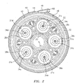
- the gear train 22 includes a plurality of gears 30, 31a-e and 32 arranged in a star gear train configuration.
- the gears may be arranged in a planetary gear train configuration, or any other type of gear train configuration.
- FIG. 3 is a schematic illustration of another gear train 22' that includes a plurality of gears 30', 31a-b' and 32' arranged in a planetary gear train configuration.
- the gears include a sun gear 30, one or more star gears 31a-e, and a ring gear 32.
- the sun gear 30 is rotatable about the centerline 28, and is connected to the input shaft 24 through a joint such as a spline joint.
- the star gears 31a-e are arranged circumferentially around the centerline 28.
- the star gears 31a-e are radially meshed between the sun gear 30 and the ring gear 32.
- Each of the star gears 31a-e is rotatable about a respective axis 34a-e.
- Each of the star gears 31a-e is rotatably connected to a stationary gear carrier 36 through a respective bearing 38a-e.
- Each bearing 38a-e may be a journal bearing as illustrated in FIGS. 1 and 2 , or alternatively any other type of bearing such as a roller element bearing, etc.
- the gear carrier 36 is connected to a turbine engine case through a support strut and/or a flexible support.
- the ring gear 32 is rotatable about the centerline 28, and is connected to the output element 26 through a joint such as a bolted flange joint.
- the ring gear may be connected to the input element and the sun gear may be connected to the output element.
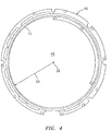
- the turbine engine system 20 also includes a fluid collection gutter 40 that at least partially circumscribes the gear train 22.
- the gutter 40 of FIG. 2 is configured as an annular body that extends circumferentially around the centerline 28.
- the gutter 40 includes a gutter inner surface 42, a fluid collection channel 44 and a fluid return conduit 46.
- the inner surface 42 at least partially defines a bore 48 (e.g., an axial gutter bore) in which the gear train 22 is arranged.
- the bore 48 has an inner surface 42 that is defined by a substantially circular cross-sectional geometry.
- the inner surface 42 has a bore area defined by a surface radius 50.
- the bore 48 may have various other non-circular (e.g., arcuate or polygonal) cross-sectional geometries that define the bore area.
- the channel 44 is defined by one or more surfaces of the gutter 40, which may include a channel end surface 52 and opposing channel side surfaces 54 and 56. That is, geometrically, the channel 44 extends radially outward into the gutter 40 from the inner surface 42 to the end surface 52. Axially, the channel 44 extends within the gutter 40 between the side surfaces 54 and 56. Circumferentially, the channel 44 extends through the gutter 40 to a channel outlet 58, which is also an inlet (e.g., scoop) for the conduit 46.
- a channel outlet 58 which is also an inlet (e.g., scoop) for the conduit 46.
- the channel 44 has a substantially rectangular cross-sectional geometry with a cross-sectional channel area. Various other cross-sectional geometries may define the channel, as described below.
- At least a portion of the area of the channel 44, located proximate (e.g., adjacent) and upstream of the channel outlet 58, is substantially equal to or less than between about two percent of the bore area.
- the channel height 60 in the engine radial direction, extends from the gutter inner surface 42 to the gutter end surface 52, and is substantially equal to or less than between about eight percent of the surface radius 50.
- the channel width 62 in the engine axial direction, extends between the gutter side surfaces 54 and 56, and is substantially equal to or less than between about five and about fifteen percent of the surface radius 50.
- the channel outlet 58 has a substantially rectangular cross-sectional geometry.
- the channel outlet may have various other cross-sectional geometries that define the outlet area as described below.
- the rectangular cross-sectional geometry defines a cross-sectional outlet area that is substantially equal to between about fifty-five and about seventy-five percent of the channel area. This dimensional relationship may further increase the fluid capture efficiency of the gutter 40 as described below.
- the conduit 46 is defined by one or more interior surfaces of the gutter 40, which may include opposing conduit end surfaces 64a-b and opposing conduit side surfaces 66a-b. In the engine radial direction, the conduit 46 extends within the gutter 40 between the end surfaces 64a-b. In the engine axial direction, the conduit 46 extends within the gutter 40 between the side surfaces 66a-b. The conduit 46 extends through the gutter 40 and may at least partially spiral around the centerline 28 from the channel outlet 58 to a conduit outlet 68 (see FIG. 2 ).
- the gutter 40 is connected to a stationary support 70 such as a support strut that connects a bearing 72 to the turbine engine case.
- the gear train 22 is arranged and mated with the gutter 40.
- the channel 44 is aligned in the engine axial direction with one or more fluid passages 74 included in the gear train 22. These fluid passages 74 are arranged circumferentially around the centerline 28, and extend in the engine radial direction through the ring gear 32.
- the channel 44 is arranged in the engine axial direction between a pair of annular seals 76 (e.g., knife edge seals), which engage (e.g., contact) the gutter inner surface 42 in the engine radial direction. In this manner, the fluid passages 74 are fluidly coupled to the channel 44 and thus to the conduit 46 through the channel 44.
- annular seals 76 e.g., knife edge seals
- an inlet manifold 78 provides lubrication and/or heat exchange fluid (e.g., lubrication oil) to the gear train 22.
- the fluid may lubricate meshing surfaces of the sun, star and ring gears 30, 31a-e and 32 and/or engaging surfaces of the star gears 31a-e and the bearings 38a-e.
- the fluid may also or alternatively remove heat energy from the sun, star and ring gears 30-32 and/or the bearings 38a-e.
- the fluid is collected from the gear train 22 with the gutter 40. Centrifugal force induced by rotation of the ring gear 32, for example, may cause at least a portion of the fluid within the gear train 22 to flow through the fluid passages 74 and radially into the channel 44.
- the channel outlet 58 directs (e.g., scoops) the fluid from the channel 44 into the conduit 46.
- the conduit 46 directs the fluid to the conduit outlet 68, which may be fluidly coupled to a fluid reservoir (e.g., an auxiliary oil reservoir for the gear train 22) or to any other lubrication system component.
- the fluid may subsequently be cooled and/or filtered, and re-circulated through the gear train 22 for further gear train component lubrication and/or cooling.
- gas within a plenum 80 surrounding the gear train 22 may flow with the fluid through the fluid passages 74 into the channel 44.
- the gas may also or alternatively leak into the channel 44 from between the gutter 40 and one or more of the seals 76.
- the ratio of gas to fluid within the channel 44 may affect the capture efficiency of the gutter 40.
- capture efficiency may describe the ratio of an amount of fluid output by the channel outlet 58 to an amount of fluid that initially flows into the channel 44 from the gear train 22.
- the gas may reduce the velocity of the fluid in the engine circumferential direction. Such a reduction in circumferential velocity may cause the fluid to swirl within the channel increasing leakage at the end surface and thus the channel outlet; e.g., churn within the channel. The churning fluid may subsequently re-contact the ring gear, which may reduce power transfer efficiency of the gear train between the inlet and the outlet elements.
- the disclosed gutter 40 may reduce the ratio of gas to fluid within the channel 44 and thus increase the capture efficiency of the gutter 40 where the channel area is sized substantially equal to or less than about two percent of the bore area as set forth above. Such a configuration, for example, balances the channel area to fluid velocity relationship. Where the channel is relatively large, for example, the fluid velocity slows and may be unable to pressurize the auxiliary tanks. Where the channel is relatively small, the side leakage increases causing low capture efficiency.
- the ratio of the outlet area to the channel area may also affect the capture efficiency of the gutter 40.
- a relatively large channel outlet may receive (e.g., scoop) a relatively large amount of the gas from the channel along with the fluid. This received gas may choke or otherwise obstruct the flow of the fluid through the conduit, which may reduce the amount of the fluid the gutter collects and thus the capture efficiency of the gutter.
- a relatively small size of the channel outlet may restrict the amount of fluid that is received from the channel and thus reduce the capture efficiency of the gutter.
- the disclosed gutter 40 may reduce air choking within the conduit 46 without restricting the amount of gas received from the channel 44 where the outlet area is substantially equal to between about fifty-five and about seventy-five percent of the channel area as set forth above.
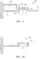
- FIG. 7 illustrates the gutter 40 with an alternative exemplary non-claimed embodiment channel 82.
- the channel 82 has a cross-sectional tapered channel geometry (e.g., a multi-region channel geometry) that defines the channel area.
- a cross-sectional tapered channel geometry e.g., a multi-region channel geometry
- the tapered channel geometry transitions into a different (e.g., substantially rectangular) cross-sectional channel geometry.
- the entire channel 82 may have the tapered channel geometry.
- the tapered channel geometry axially tapers as the channel 82 extends radially into the gutter 40 towards a channel end 84.
- the tapered channel geometry is formed by an inner region 86 and an outer region 88, each having a unique (e.g., different) geometry.
- the inner region 86 extends radially into the gutter 40 from the inner surface 42, and has a substantially rectangular geometry.
- the outer region 88 is located radially outboard of the inner region 86.
- the outer region 88 extends radially into the gutter 40 from the inner region 86 to the channel end 84, and has a substantially triangular geometry.
- the channel outlet 58' has a corresponding substantially triangular cross-sectional geometry that defines the outlet area.
- the tapered channel geometry may increase the capture efficiency of the gutter 40 by directing the received fluid radially outward towards the channel end 84.
- Canted surfaces 90 that define the outer region 88 may funnel the fluid towards the channel end 84, and reduce swirl within the channel.
- the fluid may therefore collect into a mass at (e.g., proximate, adjacent or on) the channel end 84 as the fluid flows through the channel 82 towards the channel outlet 58'.
- Such a fluid mass may also be less affected by swirling gas within the channel 82 than dispersed fluid droplets.
- swirling gas within a channel 92 with a rectangular cross-sectional geometry may cause some of the fluid to swirl out of the channel 92 and thus away from the channel outlet.
- the rectangular cross-sectional geometry therefore may decrease the capture efficiency of the gutter 94.
- the gutter 40 may have various configurations other than those described above and illustrated in the drawings.
- the gutter 40 may have a tapered cross-sectional geometry where the channel area is greater than about two percent of the bore area.
- the gutter 40 may have a channel height that is greater than about eight percent of the surface radius, and/or a channel width that is greater than about fifteen percent of the surface radius.
- the gutter 40 may have an outlet area that is less than about fifty-five percent of the channel area, or that is greater than about seventy-five percent of the channel area.
- the tapered cross-sectional geometry may have a single channel region with a substantially triangular or trapezoidal geometry, or any other type of axially tapered geometry.
- the gutter 40 may include a fluid baffle 118 (e.g., an apertured oil baffle) as illustrated in FIG. 1 , or may be configured without a baffle as illustrated in FIG. 10 .
- the gutter 40 may be configured as a stator as described above, or alternatively configured to rotate about the centerline 28; e.g., with the ring gear 32.
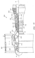
- FIG. 11 is a side cutaway illustration of a geared turbine engine 220 which may include the turbine engine system 20 of FIG. 1 .
- the turbine engine 220 is a two-spool turbofan that generally incorporates a fan section 222, a compressor section 224, a combustor section 226 and a turbine section 228.
- Alternative engines might include an augmentor section (not shown) among other systems or features.
- the fan section 222 drives air along a bypass flowpath while the compressor section 224 drives air along a core flowpath for compression and communication into the combustor section 226 then expansion through the turbine section 228.
- turbofan gas turbine engine in the disclosed non-limiting embodiment, it should be understood that the concepts described herein are not limited to use with turbofans as the teachings may be applied to other types of turbine engines such as a three-spool (plus fan) engine wherein an intermediate spool includes an intermediate pressure compressor (IPC) between the LPC and HPC and an intermediate pressure turbine (IPT) between the HPT and LPT.
- IPC intermediate pressure compressor
- IPT intermediate pressure turbine
- the engine 220 generally includes a low spool 230 and a high spool 232 mounted for rotation about an engine central longitudinal axis A relative to an engine static structure 236 via several bearing structures 238.
- the low spool 230 generally includes an inner shaft 24 that interconnects a fan 242, a low pressure compressor 244 ("LPC") and a low pressure turbine 246 ("LPT").
- the inner shaft 24 drives a fan rotor 26 of the fan 242 directly or through a geared architecture 248 to drive the fan 242 at a lower speed than the low spool 230.
- An exemplary reduction transmission is an epicyclic transmission, namely a planetary or star gear system.
- the high spool 232 includes an outer shaft 250 that interconnects a high pressure compressor 252 ("HPC”) and high pressure turbine 254 ("HPT").
- a combustor 256 is arranged between the high pressure compressor 252 and the high pressure turbine 254.
- the inner shaft 24 and the outer shaft 250 are concentric and rotate about the engine central longitudinal axis A (e.g., the centerline 28) which is collinear with their longitudinal axes.
- Core airflow is compressed by the low pressure compressor 244 then the high pressure compressor 252, mixed with the fuel and burned in the combustor 256, then expanded over the high pressure turbine 254 and low pressure turbine 246.
- the turbines 254, 246 rotationally drive the respective low spool 230 and high spool 232 in response to the expansion.
- the main engine shafts 24, 250 are supported at a plurality of points by bearing structures 238 within the static structure 236. It should be understood that various bearing structures 238 at various locations may alternatively or additionally be provided.
- the gas turbine engine 220 is a high-bypass geared aircraft engine. In a further example, the gas turbine engine 220 bypass ratio is greater than about six (6:1).
- the geared architecture 248 can include an epicyclic gear train (e.g., the gear train 22), such as a planetary gear system or other gear system.
- An example epicyclic gear train has a gear reduction ratio of greater than about 2.3:1, and in another example is greater than about 2.5:1.
- the geared turbofan enables operation of the low spool 230 at higher speeds which can increase the operational efficiency of the low pressure compressor 244 and low pressure turbine 246 and render increased pressure in a fewer number of stages.
- a pressure ratio associated with the low pressure turbine 246 is pressure measured prior to the inlet of the low pressure turbine 246 as related to the pressure at the outlet of the low pressure turbine 246 prior to an exhaust nozzle of the gas turbine engine 220.
- the bypass ratio of the gas turbine engine 220 is greater than about ten (10:1)
- the fan diameter is significantly larger than that of the low pressure compressor 244
- the low pressure turbine 246 has a pressure ratio that is greater than about 5 (5:1). It should be understood, however, that the above parameters are only exemplary of one embodiment of a geared architecture engine and that the present disclosure is applicable to other gas turbine engines including direct drive turbofans.
- a significant amount of thrust is provided by the bypass flow path B due to the high bypass ratio.
- the fan section 222 of the gas turbine engine 220 is designed for a particular flight condition - typically cruise at about 0.8 Mach and about 35,000 feet (10668 m). This flight condition, with the gas turbine engine 220 at its best fuel consumption, is also known as bucket cruise Thrust Specific Fuel Consumption (TSFC).
- TSFC Thrust Specific Fuel Consumption
- Fan Pressure Ratio is the pressure ratio across a blade of the fan section 222 without the use of a Fan Exit Guide Vane system.
- the low Fan Pressure Ratio according to one non-limiting embodiment of the example gas turbine engine 220 is less than 1.45.
- Low Corrected Fan Tip Speed is the actual fan tip speed divided by an industry standard temperature correction of "T" / 518.7 0.5 in which "T" represents the ambient temperature in degrees Rankine.
- the Low Corrected Fan Tip Speed according to one non-limiting embodiment of the example gas turbine engine 220 is less than about 1150 fps (351 m/s).
- turbine engine system 20 of FIG. 1 may be included in various turbine engines other than the one described above.
- the turbine engine system 20, for example, may be included in a geared turbine engine where a gear train connects one or more shafts to one or more rotors in a fan section and/or a compressor section.
- the turbine engine system 20 may be included in a turbine engine configured without a gear train.
- upstream is used to orient the components of the turbine engine system 20 described above relative to the turbine engine and its axis.
- upstream is used to orient the components of the turbine engine system 20 described above relative to the turbine engine and its axis.
- downstream is used to orient the components of the turbine engine system 20 described above relative to the turbine engine and its axis.
- inner is used to orient the components of the turbine engine system 20 described above relative to the turbine engine and its axis.
- outer is used to orient the components of the turbine engine system 20 described above relative to the turbine engine and its axis.
Landscapes
- Engineering & Computer Science (AREA)
- Mechanical Engineering (AREA)
- General Engineering & Computer Science (AREA)
- Chemical & Material Sciences (AREA)
- Combustion & Propulsion (AREA)
- Retarders (AREA)
- General Details Of Gearings (AREA)
Claims (10)
- System für einen Gasturbinenmotor, umfassend:einen Getriebezug (22) mit einer axialen Mittellinie (28); undeine Rinne (40), die radial außerhalb der axialen Mittellinie (28) angeordnet ist, wobei die Rinne (40) zumindest teilweise den Getriebezug (22) umgrenzt und Folgendes beinhaltet:eine Innenfläche (42); undeinen Kanal (44), der dazu konfiguriert ist, Fluid, das aus dem Getriebezug (22) gerichtet ist, aufzunehmen, wobei sich der Kanal (44) radial in die Rinne (40) von der Innenfläche (42) zu einem Kanalende (84) und in Umfangsrichtung zu einem Kanalauslass (58, 58') erstreckt; dadurch gekennzeichnet, dass mindestens ein Abschnitt des Kanals (44) eine Kanalquerschnittsgeometrie aufweist, die sich axial verjüngt, wenn sich der Kanal (44) radial in Richtung des Kanalendes (84) erstreckt; und dadurch, dass der Kanalauslass (58, 58') eine dreieckige Querschnittsgeometrie aufweist.
- System nach Anspruch 1, wobei mindestens ein Abschnitt des Kanals (44), der sich benachbart zu und stromaufwärts von dem Kanalauslass (58, 58') befindet, die Kanalgeometrie aufweist.
- System nach Anspruch 1 oder 2, wobei
die Kanalgeometrie durch eine Vielzahl von Kanalregionen (86, 88) gebildet ist und jede der Kanalregionen (86, 88) eine Geometrie und eine sich axial erstreckende Breite aufweist;
die Kanalregionen (86, 88) eine innere Region (86) und eine äußere Region (88), die sich radial außerhalb der inneren Region (86) befindet, beinhalten; und
mindestens eines von Folgenden gilt:der Geometrie des inneren Bereichs (86) ist anders als die Geometrie des äußeren Bereichs (88); unddie Breite des inneren Bereichs (86) ist anders als die Breite des äußeren Bereichs (88). - System nach Anspruch 1, 2 oder 3, wobei
die Geometrie des inneren Bereichs (86) im Wesentlichen rechteckig ist; und
die Geometrie des äußeren Bereichs (88) im Wesentlichen dreieckig ist. - System nach einem der vorangehenden Ansprüche, wobei
die Kanalgeometrie eine erste Kanalgeometrie umfasst; und
die erste Kanalgeometrie in eine zweite Kanalgeometrie übergeht, wenn sich der Kanal in Umfangsrichtung innerhalb der Rinne erstreckt. - System nach einem der vorangehenden Ansprüche, wobei die Rinne (40) ferner eine Leitung (46) beinhaltet, die sich durch die Rinne (40) erstreckt und zumindest teilweise spiralartig um die Mittellinie (28) zwischen dem Kanalauslass (58, 58') und dem Leitungsauslass (68) verläuft.
- System nach einem der vorangehenden Ansprüche, wobei
der Getriebezug (22) einen oder mehrere Fluiddurchgänge (74) beinhaltet, die in Umfangsrichtung um die Mittellinie (28) angeordnet und axial mit dem Kanal (44) ausgerichtet sind; und
der eine oder die mehreren Fluiddurchgänge (74) durch den Kanal (44) fluidisch an den Kanalauslass (58, 58') gekoppelt sind. - System nach einem der vorangehenden Ansprüche, wobei der Getriebezug (22) als Planetengetriebezug oder Sterngetriebezug konfiguriert ist.
- System nach einem der vorangehenden Ansprüche, ferner umfassend:eine Vielzahl von Turbinenmotorrotoren (26), die entlang der axialen Mittellinie (28) angeordnet sind und einen ersten Rotor und einen zweiten Rotor beinhalten, wobei jeder der Motorrotoren (26) eine Vielzahl von Rotorblättern beinhaltet, die um eine Rotorscheibe angeordnet und mit dieser verbunden sind;wobei der erste Rotor durch den Getriebezug (22) mit dem zweiten Rotor verbunden ist und durch diesen angetrieben wird.
- System nach Anspruch 9, wobei der erste Rotor als Lüfterrotor konfiguriert ist und der zweite Rotor als Turbinenrotor konfiguriert ist.
Priority Applications (2)
| Application Number | Priority Date | Filing Date | Title |
|---|---|---|---|
| EP20154569.6A EP3674584B1 (de) | 2013-01-15 | 2013-01-15 | Flüssigkeitssammelrinne für einen getriebeturbinenmotor |
| EP21203811.1A EP3961068B1 (de) | 2013-01-15 | 2013-01-15 | Flüssigkeitssammelrinne für einen getriebeturbinenmotor |
Applications Claiming Priority (3)
| Application Number | Priority Date | Filing Date | Title |
|---|---|---|---|
| EP13872239.2A EP2946131B1 (de) | 2013-01-15 | 2013-01-15 | Getriebeturbinenmotor |
| EP20154569.6A EP3674584B1 (de) | 2013-01-15 | 2013-01-15 | Flüssigkeitssammelrinne für einen getriebeturbinenmotor |
| PCT/US2013/021577 WO2014112978A1 (en) | 2013-01-15 | 2013-01-15 | Fluid collection gutter for a geared turbine engine |
Related Parent Applications (2)
| Application Number | Title | Priority Date | Filing Date |
|---|---|---|---|
| EP13872239.2A Division-Into EP2946131B1 (de) | 2013-01-15 | 2013-01-15 | Getriebeturbinenmotor |
| EP13872239.2A Division EP2946131B1 (de) | 2013-01-15 | 2013-01-15 | Getriebeturbinenmotor |
Related Child Applications (1)
| Application Number | Title | Priority Date | Filing Date |
|---|---|---|---|
| EP21203811.1A Division EP3961068B1 (de) | 2013-01-15 | 2013-01-15 | Flüssigkeitssammelrinne für einen getriebeturbinenmotor |
Publications (2)
| Publication Number | Publication Date |
|---|---|
| EP3674584A1 EP3674584A1 (de) | 2020-07-01 |
| EP3674584B1 true EP3674584B1 (de) | 2021-11-03 |
Family
ID=51209938
Family Applications (3)
| Application Number | Title | Priority Date | Filing Date |
|---|---|---|---|
| EP20154569.6A Active EP3674584B1 (de) | 2013-01-15 | 2013-01-15 | Flüssigkeitssammelrinne für einen getriebeturbinenmotor |
| EP13872239.2A Active EP2946131B1 (de) | 2013-01-15 | 2013-01-15 | Getriebeturbinenmotor |
| EP21203811.1A Active EP3961068B1 (de) | 2013-01-15 | 2013-01-15 | Flüssigkeitssammelrinne für einen getriebeturbinenmotor |
Family Applications After (2)
| Application Number | Title | Priority Date | Filing Date |
|---|---|---|---|
| EP13872239.2A Active EP2946131B1 (de) | 2013-01-15 | 2013-01-15 | Getriebeturbinenmotor |
| EP21203811.1A Active EP3961068B1 (de) | 2013-01-15 | 2013-01-15 | Flüssigkeitssammelrinne für einen getriebeturbinenmotor |
Country Status (3)
| Country | Link |
|---|---|
| US (2) | US10287915B2 (de) |
| EP (3) | EP3674584B1 (de) |
| WO (1) | WO2014112978A1 (de) |
Cited By (1)
| Publication number | Priority date | Publication date | Assignee | Title |
|---|---|---|---|---|
| US11879541B2 (en) | 2022-04-01 | 2024-01-23 | General Electric Company | Oil scavenge system for a gearbox |
Families Citing this family (17)
| Publication number | Priority date | Publication date | Assignee | Title |
|---|---|---|---|---|
| US9657586B2 (en) * | 2014-04-24 | 2017-05-23 | Hamilton Sundstrand Corporation | Turbomachine starter oil filtration system |
| US10208849B2 (en) * | 2014-08-01 | 2019-02-19 | Ge Avio S.R.L. | Mechanical gear transmission |
| DE102018208038A1 (de) * | 2018-05-23 | 2019-11-28 | MTU Aero Engines AG | Lagerkammergehäuse für eine strömungsmaschine |
| FR3084407B1 (fr) | 2018-07-26 | 2021-04-30 | Safran Aircraft Engines | Gouttiere de canalisation d'huile de lubrification d'une turbomachine d'aeronef |
| US11506079B2 (en) | 2019-09-09 | 2022-11-22 | Raytheon Technologies Corporation | Fluid diffusion device for sealed bearing compartment drainback system |
| US11162421B2 (en) | 2019-10-22 | 2021-11-02 | Pratt & Whitney Canada Corp. | Bearing cavity and method of evacuating oil therefrom |
| US11719127B2 (en) | 2019-10-23 | 2023-08-08 | Raytheon Technologies Corporation | Oil drainback assembly for a bearing compartment of a gas turbine engine |
| US11970972B2 (en) | 2019-10-23 | 2024-04-30 | Rtx Corporation | Windage blocker for oil routing |
| US11448309B2 (en) | 2020-01-17 | 2022-09-20 | Raytheon Technologies Corporation | Geared architecture gas turbine engine with planetary gear oil scavenge |
| FR3110194B1 (fr) | 2020-05-13 | 2022-11-18 | Safran Aircraft Engines | Turbomachine d’aeronef comprenant un dispositif de lubrification d’un palier |
| US11859546B2 (en) | 2022-04-01 | 2024-01-02 | General Electric Company | Eccentric gutter for an epicyclical gear train |
| US12345201B2 (en) | 2022-06-22 | 2025-07-01 | General Electric Company | Gearbox assembly with lubricant extraction volume ratio |
| US12326115B2 (en) * | 2022-06-22 | 2025-06-10 | General Electric Company | Gearbox assembly with lubricant extraction volume ratio |
| US12523176B2 (en) | 2022-06-22 | 2026-01-13 | General Electric Company | Gearbox assembly with lubricant extraction volume ratio |
| US12421898B2 (en) | 2022-06-22 | 2025-09-23 | General Electric Company | Gearbox assembly with lubricant extraction volume ratio |
| US12320418B2 (en) * | 2022-06-22 | 2025-06-03 | General Electric Company | Gearbox assembly with lubricant extraction volume ratio |
| FR3143081B1 (fr) * | 2022-12-09 | 2025-11-14 | Safran Trans Systems | Gouttière de récupération d’huile de lubrification pour réducteur mécanique comprenant un déflecteur amélioré |
Family Cites Families (36)
| Publication number | Priority date | Publication date | Assignee | Title |
|---|---|---|---|---|
| DE3137947C2 (de) * | 1980-09-26 | 1983-10-27 | Rolls-Royce Ltd., London | Für beliebige Flugmanöver taugliches Schmierölsystem für Gasturbinentriebwerke |
| JPS58168804A (ja) * | 1982-03-26 | 1983-10-05 | Iseki & Co Ltd | 燃焼装置における燃料の供給装置 |
| US4630711A (en) * | 1984-06-27 | 1986-12-23 | Societe Anonyme D.B.A. | Device for lubricating a geartrain |
| US5472383A (en) * | 1993-12-27 | 1995-12-05 | United Technologies Corporation | Lubrication system for a planetary gear train |
| US5433674A (en) * | 1994-04-12 | 1995-07-18 | United Technologies Corporation | Coupling system for a planetary gear train |
| US6223616B1 (en) * | 1999-12-22 | 2001-05-01 | United Technologies Corporation | Star gear system with lubrication circuit and lubrication method therefor |
| US6996968B2 (en) * | 2003-12-17 | 2006-02-14 | United Technologies Corporation | Bifurcated oil scavenge system for a gas turbine engine |
| US7591754B2 (en) | 2006-03-22 | 2009-09-22 | United Technologies Corporation | Epicyclic gear train integral sun gear coupling design |
| US7704178B2 (en) | 2006-07-05 | 2010-04-27 | United Technologies Corporation | Oil baffle for gas turbine fan drive gear system |
| US7926260B2 (en) | 2006-07-05 | 2011-04-19 | United Technologies Corporation | Flexible shaft for gas turbine engine |
| US8753243B2 (en) | 2006-08-15 | 2014-06-17 | United Technologies Corporation | Ring gear mounting arrangement with oil scavenge scheme |
| US7699530B2 (en) * | 2006-09-28 | 2010-04-20 | Pratt & Whitney Canada Corp. | Oil scavenge system for gas turbine engine bearing cavity |
| US7878303B2 (en) * | 2006-11-14 | 2011-02-01 | Rolls-Royce Corporation | Lubrication scavenge system |
| US8215454B2 (en) | 2006-11-22 | 2012-07-10 | United Technologies Corporation | Lubrication system with tolerance for reduced gravity |
| US8020665B2 (en) * | 2006-11-22 | 2011-09-20 | United Technologies Corporation | Lubrication system with extended emergency operability |
| US8210316B2 (en) * | 2006-12-12 | 2012-07-03 | United Technologies Corporation | Oil scavenge system for a gas turbine engine |
| US8205432B2 (en) * | 2007-10-03 | 2012-06-26 | United Technologies Corporation | Epicyclic gear train for turbo fan engine |
| GB0816562D0 (en) * | 2008-09-11 | 2008-10-15 | Rolls Royce Plc | Lubricant scavenge arrangement |
| US8366578B2 (en) | 2008-10-30 | 2013-02-05 | Caterpillar Inc. | Apparatus and method for lubricating a gear |
| US8230974B2 (en) | 2009-05-22 | 2012-07-31 | United Technologies Corporation | Windmill and zero gravity lubrication system for a gas turbine engine |
| US8246503B2 (en) | 2009-06-10 | 2012-08-21 | United Technologies Corporation | Epicyclic gear system with improved lubrication system |
| US8172716B2 (en) * | 2009-06-25 | 2012-05-08 | United Technologies Corporation | Epicyclic gear system with superfinished journal bearing |
| US8333678B2 (en) | 2009-06-26 | 2012-12-18 | United Technologies Corporation | Epicyclic gear system with load share reduction |
| US8381878B2 (en) | 2009-11-12 | 2013-02-26 | United Technologies Corporation | Oil capture and bypass system |
| WO2011096065A1 (ja) * | 2010-02-04 | 2011-08-11 | トヨタ自動車株式会社 | 潤滑油供給装置 |
| JP4785976B1 (ja) | 2010-04-13 | 2011-10-05 | 川崎重工業株式会社 | 遊星歯車装置 |
| JP4948620B2 (ja) * | 2010-04-13 | 2012-06-06 | 川崎重工業株式会社 | 歯車装置 |
| US8814746B2 (en) | 2010-04-15 | 2014-08-26 | The Timken Company | Two-array planetary gear system with flexpins and helical gearing |
| JP5933552B2 (ja) * | 2010-08-24 | 2016-06-15 | ボーグワーナー インコーポレーテッド | 排気ターボ過給機 |
| US9995174B2 (en) * | 2010-10-12 | 2018-06-12 | United Technologies Corporation | Planetary gear system arrangement with auxiliary oil system |
| US8813469B2 (en) | 2010-10-12 | 2014-08-26 | United Technologies Corporation | Planetary gear system arrangement with auxiliary oil system |
| WO2012105482A1 (ja) * | 2011-02-04 | 2012-08-09 | アイシン・エィ・ダブリュ株式会社 | 車両用駆動装置 |
| WO2012144035A1 (ja) * | 2011-04-20 | 2012-10-26 | トヨタ自動車株式会社 | 動力伝達装置の潤滑油供給装置 |
| US8893469B2 (en) * | 2011-06-22 | 2014-11-25 | United Technologies Corporation | Oil bypass channel deaerator for a geared turbofan engine |
| WO2014033940A1 (ja) * | 2012-08-27 | 2014-03-06 | 愛知機械工業株式会社 | オイルガータおよびこれを備える変速機 |
| CN104755707B (zh) * | 2012-11-12 | 2017-06-16 | 博格华纳公司 | 引发漩涡的轴承壳体分隔件和内芯 |
-
2013
- 2013-01-15 EP EP20154569.6A patent/EP3674584B1/de active Active
- 2013-01-15 WO PCT/US2013/021577 patent/WO2014112978A1/en not_active Ceased
- 2013-01-15 US US14/761,241 patent/US10287915B2/en active Active
- 2013-01-15 EP EP13872239.2A patent/EP2946131B1/de active Active
- 2013-01-15 EP EP21203811.1A patent/EP3961068B1/de active Active
-
2019
- 2019-05-10 US US16/409,167 patent/US11060417B2/en active Active
Cited By (1)
| Publication number | Priority date | Publication date | Assignee | Title |
|---|---|---|---|---|
| US11879541B2 (en) | 2022-04-01 | 2024-01-23 | General Electric Company | Oil scavenge system for a gearbox |
Also Published As
| Publication number | Publication date |
|---|---|
| US20150361829A1 (en) | 2015-12-17 |
| WO2014112978A1 (en) | 2014-07-24 |
| EP2946131A1 (de) | 2015-11-25 |
| US11060417B2 (en) | 2021-07-13 |
| EP2946131B1 (de) | 2020-03-04 |
| US20190271236A1 (en) | 2019-09-05 |
| EP3674584A1 (de) | 2020-07-01 |
| EP3961068B1 (de) | 2025-08-13 |
| EP3961068A1 (de) | 2022-03-02 |
| EP2946131A4 (de) | 2016-01-20 |
| US10287915B2 (en) | 2019-05-14 |
Similar Documents
| Publication | Publication Date | Title |
|---|---|---|
| US11060417B2 (en) | Fluid collection gutter for a geared turbine engine | |
| US11066945B2 (en) | Fluid collection gutter for a geared turbine engine | |
| EP3859191B1 (de) | Flüssigkeitssammelrinne für einen getriebeturbinenmotor | |
| US10890247B2 (en) | Lubrication fluid collection in a gearbox of a gas turbine engine | |
| EP3851653B1 (de) | Gasturbinenmotor mit getriebearchitektur mit planetengetriebe-ölspülung | |
| EP2971662B1 (de) | Schmiermittelzirkulierung durch eine turbinenmotorkomponente mit parallelen pumpen | |
| EP2834500B1 (de) | Thermisches konditionierungssystem und -verfahren einer turbomaschine | |
| EP1655475B1 (de) | Gegenläufiges Turbinentriebwerk | |
| US10196926B2 (en) | Lubricating a rotating component during forward and/or reverse rotation | |
| EP3199837B1 (de) | Getriebeablenkplatte, die mit schmiermitteldurchgangsauslass konfiguriert ist | |
| EP2834497B1 (de) | Wärmeverwaltung einer turbomaschine | |
| EP3088685B1 (de) | Wärmeverwaltungssystem und verfahren zur zirkulation von luft in einem gasturbinenmotor | |
| US12421898B2 (en) | Gearbox assembly with lubricant extraction volume ratio | |
| US20250137529A1 (en) | Gearbox assembly with lubricant extraction volume ratio | |
| CN112443652B (zh) | 具有收集器的用于航空发动机的齿轮组件 | |
| CN113833827B (zh) | 用于具有润滑剂储存兜部的航空发动机的齿轮组件 | |
| CN108331903B (zh) | 用于具有多个排泄口的齿轮箱的设备 | |
| EP4621192A2 (de) | Lagerölverteilungsschema |
Legal Events
| Date | Code | Title | Description |
|---|---|---|---|
| PUAI | Public reference made under article 153(3) epc to a published international application that has entered the european phase |
Free format text: ORIGINAL CODE: 0009012 |
|
| STAA | Information on the status of an ep patent application or granted ep patent |
Free format text: STATUS: THE APPLICATION HAS BEEN PUBLISHED |
|
| AC | Divisional application: reference to earlier application |
Ref document number: 2946131 Country of ref document: EP Kind code of ref document: P |
|
| AK | Designated contracting states |
Kind code of ref document: A1 Designated state(s): AL AT BE BG CH CY CZ DE DK EE ES FI FR GB GR HR HU IE IS IT LI LT LU LV MC MK MT NL NO PL PT RO RS SE SI SK SM TR |
|
| STAA | Information on the status of an ep patent application or granted ep patent |
Free format text: STATUS: REQUEST FOR EXAMINATION WAS MADE |
|
| 17P | Request for examination filed |
Effective date: 20210105 |
|
| RBV | Designated contracting states (corrected) |
Designated state(s): AL AT BE BG CH CY CZ DE DK EE ES FI FR GB GR HR HU IE IS IT LI LT LU LV MC MK MT NL NO PL PT RO RS SE SI SK SM TR |
|
| RAP1 | Party data changed (applicant data changed or rights of an application transferred) |
Owner name: RAYTHEON TECHNOLOGIES CORPORATION |
|
| GRAP | Despatch of communication of intention to grant a patent |
Free format text: ORIGINAL CODE: EPIDOSNIGR1 |
|
| STAA | Information on the status of an ep patent application or granted ep patent |
Free format text: STATUS: GRANT OF PATENT IS INTENDED |
|
| RIC1 | Information provided on ipc code assigned before grant |
Ipc: F02C 7/06 20060101ALI20210428BHEP Ipc: F02C 7/32 20060101ALI20210428BHEP Ipc: F02C 7/36 20060101ALI20210428BHEP Ipc: F02C 3/107 20060101ALI20210428BHEP Ipc: F01D 25/18 20060101ALI20210428BHEP Ipc: F16H 57/04 20100101AFI20210428BHEP |
|
| INTG | Intention to grant announced |
Effective date: 20210519 |
|
| GRAS | Grant fee paid |
Free format text: ORIGINAL CODE: EPIDOSNIGR3 |
|
| GRAA | (expected) grant |
Free format text: ORIGINAL CODE: 0009210 |
|
| STAA | Information on the status of an ep patent application or granted ep patent |
Free format text: STATUS: THE PATENT HAS BEEN GRANTED |
|
| AC | Divisional application: reference to earlier application |
Ref document number: 2946131 Country of ref document: EP Kind code of ref document: P |
|
| AK | Designated contracting states |
Kind code of ref document: B1 Designated state(s): AL AT BE BG CH CY CZ DE DK EE ES FI FR GB GR HR HU IE IS IT LI LT LU LV MC MK MT NL NO PL PT RO RS SE SI SK SM TR |
|
| REG | Reference to a national code |
Ref country code: GB Ref legal event code: FG4D |
|
| REG | Reference to a national code |
Ref country code: AT Ref legal event code: REF Ref document number: 1444229 Country of ref document: AT Kind code of ref document: T Effective date: 20211115 Ref country code: CH Ref legal event code: EP |
|
| REG | Reference to a national code |
Ref country code: DE Ref legal event code: R096 Ref document number: 602013079953 Country of ref document: DE |
|
| REG | Reference to a national code |
Ref country code: IE Ref legal event code: FG4D |
|
| REG | Reference to a national code |
Ref country code: LT Ref legal event code: MG9D |
|
| REG | Reference to a national code |
Ref country code: NL Ref legal event code: MP Effective date: 20211103 |
|
| REG | Reference to a national code |
Ref country code: AT Ref legal event code: MK05 Ref document number: 1444229 Country of ref document: AT Kind code of ref document: T Effective date: 20211103 |
|
| PG25 | Lapsed in a contracting state [announced via postgrant information from national office to epo] |
Ref country code: RS Free format text: LAPSE BECAUSE OF FAILURE TO SUBMIT A TRANSLATION OF THE DESCRIPTION OR TO PAY THE FEE WITHIN THE PRESCRIBED TIME-LIMIT Effective date: 20211103 Ref country code: LT Free format text: LAPSE BECAUSE OF FAILURE TO SUBMIT A TRANSLATION OF THE DESCRIPTION OR TO PAY THE FEE WITHIN THE PRESCRIBED TIME-LIMIT Effective date: 20211103 Ref country code: FI Free format text: LAPSE BECAUSE OF FAILURE TO SUBMIT A TRANSLATION OF THE DESCRIPTION OR TO PAY THE FEE WITHIN THE PRESCRIBED TIME-LIMIT Effective date: 20211103 Ref country code: BG Free format text: LAPSE BECAUSE OF FAILURE TO SUBMIT A TRANSLATION OF THE DESCRIPTION OR TO PAY THE FEE WITHIN THE PRESCRIBED TIME-LIMIT Effective date: 20220203 Ref country code: AT Free format text: LAPSE BECAUSE OF FAILURE TO SUBMIT A TRANSLATION OF THE DESCRIPTION OR TO PAY THE FEE WITHIN THE PRESCRIBED TIME-LIMIT Effective date: 20211103 |
|
| PG25 | Lapsed in a contracting state [announced via postgrant information from national office to epo] |
Ref country code: IS Free format text: LAPSE BECAUSE OF FAILURE TO SUBMIT A TRANSLATION OF THE DESCRIPTION OR TO PAY THE FEE WITHIN THE PRESCRIBED TIME-LIMIT Effective date: 20220303 Ref country code: SE Free format text: LAPSE BECAUSE OF FAILURE TO SUBMIT A TRANSLATION OF THE DESCRIPTION OR TO PAY THE FEE WITHIN THE PRESCRIBED TIME-LIMIT Effective date: 20211103 Ref country code: PT Free format text: LAPSE BECAUSE OF FAILURE TO SUBMIT A TRANSLATION OF THE DESCRIPTION OR TO PAY THE FEE WITHIN THE PRESCRIBED TIME-LIMIT Effective date: 20220303 Ref country code: PL Free format text: LAPSE BECAUSE OF FAILURE TO SUBMIT A TRANSLATION OF THE DESCRIPTION OR TO PAY THE FEE WITHIN THE PRESCRIBED TIME-LIMIT Effective date: 20211103 Ref country code: NO Free format text: LAPSE BECAUSE OF FAILURE TO SUBMIT A TRANSLATION OF THE DESCRIPTION OR TO PAY THE FEE WITHIN THE PRESCRIBED TIME-LIMIT Effective date: 20220203 Ref country code: NL Free format text: LAPSE BECAUSE OF FAILURE TO SUBMIT A TRANSLATION OF THE DESCRIPTION OR TO PAY THE FEE WITHIN THE PRESCRIBED TIME-LIMIT Effective date: 20211103 Ref country code: LV Free format text: LAPSE BECAUSE OF FAILURE TO SUBMIT A TRANSLATION OF THE DESCRIPTION OR TO PAY THE FEE WITHIN THE PRESCRIBED TIME-LIMIT Effective date: 20211103 Ref country code: HR Free format text: LAPSE BECAUSE OF FAILURE TO SUBMIT A TRANSLATION OF THE DESCRIPTION OR TO PAY THE FEE WITHIN THE PRESCRIBED TIME-LIMIT Effective date: 20211103 Ref country code: GR Free format text: LAPSE BECAUSE OF FAILURE TO SUBMIT A TRANSLATION OF THE DESCRIPTION OR TO PAY THE FEE WITHIN THE PRESCRIBED TIME-LIMIT Effective date: 20220204 Ref country code: ES Free format text: LAPSE BECAUSE OF FAILURE TO SUBMIT A TRANSLATION OF THE DESCRIPTION OR TO PAY THE FEE WITHIN THE PRESCRIBED TIME-LIMIT Effective date: 20211103 |
|
| PG25 | Lapsed in a contracting state [announced via postgrant information from national office to epo] |
Ref country code: SM Free format text: LAPSE BECAUSE OF FAILURE TO SUBMIT A TRANSLATION OF THE DESCRIPTION OR TO PAY THE FEE WITHIN THE PRESCRIBED TIME-LIMIT Effective date: 20211103 Ref country code: SK Free format text: LAPSE BECAUSE OF FAILURE TO SUBMIT A TRANSLATION OF THE DESCRIPTION OR TO PAY THE FEE WITHIN THE PRESCRIBED TIME-LIMIT Effective date: 20211103 Ref country code: RO Free format text: LAPSE BECAUSE OF FAILURE TO SUBMIT A TRANSLATION OF THE DESCRIPTION OR TO PAY THE FEE WITHIN THE PRESCRIBED TIME-LIMIT Effective date: 20211103 Ref country code: EE Free format text: LAPSE BECAUSE OF FAILURE TO SUBMIT A TRANSLATION OF THE DESCRIPTION OR TO PAY THE FEE WITHIN THE PRESCRIBED TIME-LIMIT Effective date: 20211103 Ref country code: DK Free format text: LAPSE BECAUSE OF FAILURE TO SUBMIT A TRANSLATION OF THE DESCRIPTION OR TO PAY THE FEE WITHIN THE PRESCRIBED TIME-LIMIT Effective date: 20211103 Ref country code: CZ Free format text: LAPSE BECAUSE OF FAILURE TO SUBMIT A TRANSLATION OF THE DESCRIPTION OR TO PAY THE FEE WITHIN THE PRESCRIBED TIME-LIMIT Effective date: 20211103 |
|
| REG | Reference to a national code |
Ref country code: DE Ref legal event code: R097 Ref document number: 602013079953 Country of ref document: DE |
|
| PG25 | Lapsed in a contracting state [announced via postgrant information from national office to epo] |
Ref country code: MC Free format text: LAPSE BECAUSE OF FAILURE TO SUBMIT A TRANSLATION OF THE DESCRIPTION OR TO PAY THE FEE WITHIN THE PRESCRIBED TIME-LIMIT Effective date: 20211103 |
|
| REG | Reference to a national code |
Ref country code: CH Ref legal event code: PL |
|
| PLBE | No opposition filed within time limit |
Free format text: ORIGINAL CODE: 0009261 |
|
| STAA | Information on the status of an ep patent application or granted ep patent |
Free format text: STATUS: NO OPPOSITION FILED WITHIN TIME LIMIT |
|
| REG | Reference to a national code |
Ref country code: BE Ref legal event code: MM Effective date: 20220131 |
|
| 26N | No opposition filed |
Effective date: 20220804 |
|
| PG25 | Lapsed in a contracting state [announced via postgrant information from national office to epo] |
Ref country code: LU Free format text: LAPSE BECAUSE OF NON-PAYMENT OF DUE FEES Effective date: 20220115 Ref country code: AL Free format text: LAPSE BECAUSE OF FAILURE TO SUBMIT A TRANSLATION OF THE DESCRIPTION OR TO PAY THE FEE WITHIN THE PRESCRIBED TIME-LIMIT Effective date: 20211103 |
|
| PG25 | Lapsed in a contracting state [announced via postgrant information from national office to epo] |
Ref country code: SI Free format text: LAPSE BECAUSE OF FAILURE TO SUBMIT A TRANSLATION OF THE DESCRIPTION OR TO PAY THE FEE WITHIN THE PRESCRIBED TIME-LIMIT Effective date: 20211103 Ref country code: BE Free format text: LAPSE BECAUSE OF NON-PAYMENT OF DUE FEES Effective date: 20220131 |
|
| PG25 | Lapsed in a contracting state [announced via postgrant information from national office to epo] |
Ref country code: LI Free format text: LAPSE BECAUSE OF NON-PAYMENT OF DUE FEES Effective date: 20220131 Ref country code: CH Free format text: LAPSE BECAUSE OF NON-PAYMENT OF DUE FEES Effective date: 20220131 |
|
| PG25 | Lapsed in a contracting state [announced via postgrant information from national office to epo] |
Ref country code: IE Free format text: LAPSE BECAUSE OF NON-PAYMENT OF DUE FEES Effective date: 20220115 |
|
| P01 | Opt-out of the competence of the unified patent court (upc) registered |
Effective date: 20230521 |
|
| PG25 | Lapsed in a contracting state [announced via postgrant information from national office to epo] |
Ref country code: MK Free format text: LAPSE BECAUSE OF FAILURE TO SUBMIT A TRANSLATION OF THE DESCRIPTION OR TO PAY THE FEE WITHIN THE PRESCRIBED TIME-LIMIT Effective date: 20211103 Ref country code: CY Free format text: LAPSE BECAUSE OF FAILURE TO SUBMIT A TRANSLATION OF THE DESCRIPTION OR TO PAY THE FEE WITHIN THE PRESCRIBED TIME-LIMIT Effective date: 20211103 |
|
| PG25 | Lapsed in a contracting state [announced via postgrant information from national office to epo] |
Ref country code: HU Free format text: LAPSE BECAUSE OF FAILURE TO SUBMIT A TRANSLATION OF THE DESCRIPTION OR TO PAY THE FEE WITHIN THE PRESCRIBED TIME-LIMIT; INVALID AB INITIO Effective date: 20130115 |
|
| PG25 | Lapsed in a contracting state [announced via postgrant information from national office to epo] |
Ref country code: MT Free format text: LAPSE BECAUSE OF FAILURE TO SUBMIT A TRANSLATION OF THE DESCRIPTION OR TO PAY THE FEE WITHIN THE PRESCRIBED TIME-LIMIT Effective date: 20211103 |
|
| PGFP | Annual fee paid to national office [announced via postgrant information from national office to epo] |
Ref country code: DE Payment date: 20241218 Year of fee payment: 13 |
|
| PGFP | Annual fee paid to national office [announced via postgrant information from national office to epo] |
Ref country code: IT Payment date: 20250107 Year of fee payment: 13 |
|
| REG | Reference to a national code |
Ref country code: DE Ref legal event code: R081 Ref document number: 602013079953 Country of ref document: DE Owner name: RTX CORPORATION (N.D.GES.D. STAATES DELAWARE),, US Free format text: FORMER OWNER: RAYTHEON TECHNOLOGIES CORPORATION, FARMINGTON, CT, US |
|
| PG25 | Lapsed in a contracting state [announced via postgrant information from national office to epo] |
Ref country code: TR Free format text: LAPSE BECAUSE OF FAILURE TO SUBMIT A TRANSLATION OF THE DESCRIPTION OR TO PAY THE FEE WITHIN THE PRESCRIBED TIME-LIMIT Effective date: 20211103 |
|
| PGFP | Annual fee paid to national office [announced via postgrant information from national office to epo] |
Ref country code: GB Payment date: 20251217 Year of fee payment: 14 |
|
| PGFP | Annual fee paid to national office [announced via postgrant information from national office to epo] |
Ref country code: FR Payment date: 20251217 Year of fee payment: 14 |