EP3674069A1 - Harzimprägnierungsmessvorrichtung - Google Patents
Harzimprägnierungsmessvorrichtung Download PDFInfo
- Publication number
- EP3674069A1 EP3674069A1 EP19209434.0A EP19209434A EP3674069A1 EP 3674069 A1 EP3674069 A1 EP 3674069A1 EP 19209434 A EP19209434 A EP 19209434A EP 3674069 A1 EP3674069 A1 EP 3674069A1
- Authority
- EP
- European Patent Office
- Prior art keywords
- resin
- base material
- fiber base
- stringer
- skin
- Prior art date
- Legal status (The legal status is an assumption and is not a legal conclusion. Google has not performed a legal analysis and makes no representation as to the accuracy of the status listed.)
- Granted
Links
Images

Classifications
-
- B—PERFORMING OPERATIONS; TRANSPORTING
- B29—WORKING OF PLASTICS; WORKING OF SUBSTANCES IN A PLASTIC STATE IN GENERAL
- B29C—SHAPING OR JOINING OF PLASTICS; SHAPING OF MATERIAL IN A PLASTIC STATE, NOT OTHERWISE PROVIDED FOR; AFTER-TREATMENT OF THE SHAPED PRODUCTS, e.g. REPAIRING
- B29C43/00—Compression moulding, i.e. applying external pressure to flow the moulding material; Apparatus therefor
- B29C43/32—Component parts, details or accessories; Auxiliary operations
- B29C43/58—Measuring, controlling or regulating
-
- B—PERFORMING OPERATIONS; TRANSPORTING
- B29—WORKING OF PLASTICS; WORKING OF SUBSTANCES IN A PLASTIC STATE IN GENERAL
- B29C—SHAPING OR JOINING OF PLASTICS; SHAPING OF MATERIAL IN A PLASTIC STATE, NOT OTHERWISE PROVIDED FOR; AFTER-TREATMENT OF THE SHAPED PRODUCTS, e.g. REPAIRING
- B29C70/00—Shaping composites, i.e. plastics material comprising reinforcements, fillers or preformed parts, e.g. inserts
- B29C70/04—Shaping composites, i.e. plastics material comprising reinforcements, fillers or preformed parts, e.g. inserts comprising reinforcements only, e.g. self-reinforcing plastics
- B29C70/28—Shaping operations therefor
- B29C70/54—Component parts, details or accessories; Auxiliary operations, e.g. feeding or storage of prepregs or SMC after impregnation or during ageing
- B29C70/546—Measures for feeding or distributing the matrix material in the reinforcing structure
-
- B—PERFORMING OPERATIONS; TRANSPORTING
- B29—WORKING OF PLASTICS; WORKING OF SUBSTANCES IN A PLASTIC STATE IN GENERAL
- B29C—SHAPING OR JOINING OF PLASTICS; SHAPING OF MATERIAL IN A PLASTIC STATE, NOT OTHERWISE PROVIDED FOR; AFTER-TREATMENT OF THE SHAPED PRODUCTS, e.g. REPAIRING
- B29C43/00—Compression moulding, i.e. applying external pressure to flow the moulding material; Apparatus therefor
- B29C43/32—Component parts, details or accessories; Auxiliary operations
- B29C43/36—Moulds for making articles of definite length, i.e. discrete articles
- B29C43/3642—Bags, bleeder sheets or cauls for isostatic pressing
-
- B—PERFORMING OPERATIONS; TRANSPORTING
- B29—WORKING OF PLASTICS; WORKING OF SUBSTANCES IN A PLASTIC STATE IN GENERAL
- B29C—SHAPING OR JOINING OF PLASTICS; SHAPING OF MATERIAL IN A PLASTIC STATE, NOT OTHERWISE PROVIDED FOR; AFTER-TREATMENT OF THE SHAPED PRODUCTS, e.g. REPAIRING
- B29C70/00—Shaping composites, i.e. plastics material comprising reinforcements, fillers or preformed parts, e.g. inserts
- B29C70/04—Shaping composites, i.e. plastics material comprising reinforcements, fillers or preformed parts, e.g. inserts comprising reinforcements only, e.g. self-reinforcing plastics
- B29C70/28—Shaping operations therefor
- B29C70/40—Shaping or impregnating by compression not applied
- B29C70/42—Shaping or impregnating by compression not applied for producing articles of definite length, i.e. discrete articles
- B29C70/44—Shaping or impregnating by compression not applied for producing articles of definite length, i.e. discrete articles using isostatic pressure, e.g. pressure difference-moulding, vacuum bag-moulding, autoclave-moulding or expanding rubber-moulding
- B29C70/443—Shaping or impregnating by compression not applied for producing articles of definite length, i.e. discrete articles using isostatic pressure, e.g. pressure difference-moulding, vacuum bag-moulding, autoclave-moulding or expanding rubber-moulding and impregnating by vacuum or injection
-
- B—PERFORMING OPERATIONS; TRANSPORTING
- B29—WORKING OF PLASTICS; WORKING OF SUBSTANCES IN A PLASTIC STATE IN GENERAL
- B29C—SHAPING OR JOINING OF PLASTICS; SHAPING OF MATERIAL IN A PLASTIC STATE, NOT OTHERWISE PROVIDED FOR; AFTER-TREATMENT OF THE SHAPED PRODUCTS, e.g. REPAIRING
- B29C70/00—Shaping composites, i.e. plastics material comprising reinforcements, fillers or preformed parts, e.g. inserts
- B29C70/04—Shaping composites, i.e. plastics material comprising reinforcements, fillers or preformed parts, e.g. inserts comprising reinforcements only, e.g. self-reinforcing plastics
- B29C70/28—Shaping operations therefor
- B29C70/40—Shaping or impregnating by compression not applied
- B29C70/42—Shaping or impregnating by compression not applied for producing articles of definite length, i.e. discrete articles
- B29C70/46—Shaping or impregnating by compression not applied for producing articles of definite length, i.e. discrete articles using matched moulds, e.g. for deforming sheet moulding compounds [SMC] or prepregs
- B29C70/48—Shaping or impregnating by compression not applied for producing articles of definite length, i.e. discrete articles using matched moulds, e.g. for deforming sheet moulding compounds [SMC] or prepregs and impregnating the reinforcements in the closed mould, e.g. resin transfer moulding [RTM], e.g. by vacuum
-
- B—PERFORMING OPERATIONS; TRANSPORTING
- B29—WORKING OF PLASTICS; WORKING OF SUBSTANCES IN A PLASTIC STATE IN GENERAL
- B29D—PRODUCING PARTICULAR ARTICLES FROM PLASTICS OR FROM SUBSTANCES IN A PLASTIC STATE
- B29D99/00—Subject matter not provided for in other groups of this subclass
- B29D99/001—Producing wall or panel-like structures, e.g. for hulls, fuselages, or buildings
- B29D99/0014—Producing wall or panel-like structures, e.g. for hulls, fuselages, or buildings provided with ridges or ribs, e.g. joined ribs
-
- G—PHYSICS
- G01—MEASURING; TESTING
- G01F—MEASURING VOLUME, VOLUME FLOW, MASS FLOW OR LIQUID LEVEL; METERING BY VOLUME
- G01F23/00—Indicating or measuring liquid level or level of fluent solid material, e.g. indicating in terms of volume or indicating by means of an alarm
- G01F23/22—Indicating or measuring liquid level or level of fluent solid material, e.g. indicating in terms of volume or indicating by means of an alarm by measuring physical variables, other than linear dimensions, pressure or weight, dependent on the level to be measured, e.g. by difference of heat transfer of steam or water
- G01F23/26—Indicating or measuring liquid level or level of fluent solid material, e.g. indicating in terms of volume or indicating by means of an alarm by measuring physical variables, other than linear dimensions, pressure or weight, dependent on the level to be measured, e.g. by difference of heat transfer of steam or water by measuring variations of capacity or inductance of capacitors or inductors arising from the presence of liquid or fluent solid material in the electric or electromagnetic fields
- G01F23/263—Indicating or measuring liquid level or level of fluent solid material, e.g. indicating in terms of volume or indicating by means of an alarm by measuring physical variables, other than linear dimensions, pressure or weight, dependent on the level to be measured, e.g. by difference of heat transfer of steam or water by measuring variations of capacity or inductance of capacitors or inductors arising from the presence of liquid or fluent solid material in the electric or electromagnetic fields by measuring variations in capacitance of capacitors
-
- G—PHYSICS
- G01—MEASURING; TESTING
- G01F—MEASURING VOLUME, VOLUME FLOW, MASS FLOW OR LIQUID LEVEL; METERING BY VOLUME
- G01F23/00—Indicating or measuring liquid level or level of fluent solid material, e.g. indicating in terms of volume or indicating by means of an alarm
- G01F23/22—Indicating or measuring liquid level or level of fluent solid material, e.g. indicating in terms of volume or indicating by means of an alarm by measuring physical variables, other than linear dimensions, pressure or weight, dependent on the level to be measured, e.g. by difference of heat transfer of steam or water
- G01F23/26—Indicating or measuring liquid level or level of fluent solid material, e.g. indicating in terms of volume or indicating by means of an alarm by measuring physical variables, other than linear dimensions, pressure or weight, dependent on the level to be measured, e.g. by difference of heat transfer of steam or water by measuring variations of capacity or inductance of capacitors or inductors arising from the presence of liquid or fluent solid material in the electric or electromagnetic fields
- G01F23/263—Indicating or measuring liquid level or level of fluent solid material, e.g. indicating in terms of volume or indicating by means of an alarm by measuring physical variables, other than linear dimensions, pressure or weight, dependent on the level to be measured, e.g. by difference of heat transfer of steam or water by measuring variations of capacity or inductance of capacitors or inductors arising from the presence of liquid or fluent solid material in the electric or electromagnetic fields by measuring variations in capacitance of capacitors
- G01F23/266—Indicating or measuring liquid level or level of fluent solid material, e.g. indicating in terms of volume or indicating by means of an alarm by measuring physical variables, other than linear dimensions, pressure or weight, dependent on the level to be measured, e.g. by difference of heat transfer of steam or water by measuring variations of capacity or inductance of capacitors or inductors arising from the presence of liquid or fluent solid material in the electric or electromagnetic fields by measuring variations in capacitance of capacitors measuring circuits therefor
-
- B—PERFORMING OPERATIONS; TRANSPORTING
- B29—WORKING OF PLASTICS; WORKING OF SUBSTANCES IN A PLASTIC STATE IN GENERAL
- B29C—SHAPING OR JOINING OF PLASTICS; SHAPING OF MATERIAL IN A PLASTIC STATE, NOT OTHERWISE PROVIDED FOR; AFTER-TREATMENT OF THE SHAPED PRODUCTS, e.g. REPAIRING
- B29C43/00—Compression moulding, i.e. applying external pressure to flow the moulding material; Apparatus therefor
- B29C43/32—Component parts, details or accessories; Auxiliary operations
- B29C43/36—Moulds for making articles of definite length, i.e. discrete articles
- B29C43/3642—Bags, bleeder sheets or cauls for isostatic pressing
- B29C2043/3652—Elastic moulds or mould parts, e.g. cores or inserts
-
- B—PERFORMING OPERATIONS; TRANSPORTING
- B29—WORKING OF PLASTICS; WORKING OF SUBSTANCES IN A PLASTIC STATE IN GENERAL
- B29C—SHAPING OR JOINING OF PLASTICS; SHAPING OF MATERIAL IN A PLASTIC STATE, NOT OTHERWISE PROVIDED FOR; AFTER-TREATMENT OF THE SHAPED PRODUCTS, e.g. REPAIRING
- B29C43/00—Compression moulding, i.e. applying external pressure to flow the moulding material; Apparatus therefor
- B29C43/32—Component parts, details or accessories; Auxiliary operations
- B29C43/58—Measuring, controlling or regulating
- B29C2043/5875—Measuring, controlling or regulating the material feed to the moulds or mould parts, e.g. controlling feed flow, velocity, weight, doses
- B29C2043/5883—Measuring, controlling or regulating the material feed to the moulds or mould parts, e.g. controlling feed flow, velocity, weight, doses ensuring cavity filling, e.g. providing overflow means
-
- B—PERFORMING OPERATIONS; TRANSPORTING
- B29—WORKING OF PLASTICS; WORKING OF SUBSTANCES IN A PLASTIC STATE IN GENERAL
- B29C—SHAPING OR JOINING OF PLASTICS; SHAPING OF MATERIAL IN A PLASTIC STATE, NOT OTHERWISE PROVIDED FOR; AFTER-TREATMENT OF THE SHAPED PRODUCTS, e.g. REPAIRING
- B29C43/00—Compression moulding, i.e. applying external pressure to flow the moulding material; Apparatus therefor
- B29C43/02—Compression moulding, i.e. applying external pressure to flow the moulding material; Apparatus therefor of articles of definite length, i.e. discrete articles
- B29C43/10—Isostatic pressing, i.e. using non-rigid pressure-exerting members against rigid parts or dies
- B29C43/12—Isostatic pressing, i.e. using non-rigid pressure-exerting members against rigid parts or dies using bags surrounding the moulding material or using membranes contacting the moulding material
-
- B—PERFORMING OPERATIONS; TRANSPORTING
- B29—WORKING OF PLASTICS; WORKING OF SUBSTANCES IN A PLASTIC STATE IN GENERAL
- B29K—INDEXING SCHEME ASSOCIATED WITH SUBCLASSES B29B, B29C OR B29D, RELATING TO MOULDING MATERIALS OR TO MATERIALS FOR MOULDS, REINFORCEMENTS, FILLERS OR PREFORMED PARTS, e.g. INSERTS
- B29K2105/00—Condition, form or state of moulded material or of the material to be shaped
- B29K2105/06—Condition, form or state of moulded material or of the material to be shaped containing reinforcements, fillers or inserts
- B29K2105/08—Condition, form or state of moulded material or of the material to be shaped containing reinforcements, fillers or inserts of continuous length, e.g. cords, rovings, mats, fabrics, strands or yarns
-
- B—PERFORMING OPERATIONS; TRANSPORTING
- B29—WORKING OF PLASTICS; WORKING OF SUBSTANCES IN A PLASTIC STATE IN GENERAL
- B29L—INDEXING SCHEME ASSOCIATED WITH SUBCLASS B29C, RELATING TO PARTICULAR ARTICLES
- B29L2031/00—Other particular articles
- B29L2031/30—Vehicles, e.g. ships or aircraft, or body parts thereof
- B29L2031/3076—Aircrafts
-
- B—PERFORMING OPERATIONS; TRANSPORTING
- B29—WORKING OF PLASTICS; WORKING OF SUBSTANCES IN A PLASTIC STATE IN GENERAL
- B29L—INDEXING SCHEME ASSOCIATED WITH SUBCLASS B29C, RELATING TO PARTICULAR ARTICLES
- B29L2031/00—Other particular articles
- B29L2031/30—Vehicles, e.g. ships or aircraft, or body parts thereof
- B29L2031/3076—Aircrafts
- B29L2031/3082—Fuselages
-
- B—PERFORMING OPERATIONS; TRANSPORTING
- B29—WORKING OF PLASTICS; WORKING OF SUBSTANCES IN A PLASTIC STATE IN GENERAL
- B29L—INDEXING SCHEME ASSOCIATED WITH SUBCLASS B29C, RELATING TO PARTICULAR ARTICLES
- B29L2031/00—Other particular articles
- B29L2031/30—Vehicles, e.g. ships or aircraft, or body parts thereof
- B29L2031/3076—Aircrafts
- B29L2031/3085—Wings
-
- Y—GENERAL TAGGING OF NEW TECHNOLOGICAL DEVELOPMENTS; GENERAL TAGGING OF CROSS-SECTIONAL TECHNOLOGIES SPANNING OVER SEVERAL SECTIONS OF THE IPC; TECHNICAL SUBJECTS COVERED BY FORMER USPC CROSS-REFERENCE ART COLLECTIONS [XRACs] AND DIGESTS
- Y02—TECHNOLOGIES OR APPLICATIONS FOR MITIGATION OR ADAPTATION AGAINST CLIMATE CHANGE
- Y02T—CLIMATE CHANGE MITIGATION TECHNOLOGIES RELATED TO TRANSPORTATION
- Y02T50/00—Aeronautics or air transport
- Y02T50/40—Weight reduction
Definitions
- the disclosure relates to a resin impregnation measurement device.
- Composite materials such as carbon fiber reinforced plastics (CFRP) are used in aircrafts.
- JP-A Japanese Unexamined Patent Application Publication
- JP-A No. 2013-75471 discloses manufacturing a composite material by a vacuum assisted resin transfer molding (VaRTM) technique.
- the VaRTM technique manufactures composite materials by impregnating fiber base materials with resin under a vacuum pressure and thermosetting the resin.
- An aspect of the disclosure provides a resin impregnation measurement device.
- the device includes a jig and a resin impregnation sensor.
- the jig formed into an inner surface shape of a protrusion of a stringer.
- the jig includes outer surfaces including a facing surface that is to face an inner surface of the protrusion.
- the resin impregnation sensor is disposed on the facing surface of the jig.
- a composite material molding device disclosed in JP-A No. 2013-75471 includes a resin impregnation sensor that measures whether the fiber base material is impregnated with resin.
- the resin impregnation sensor is provided outside the composite material molding device. Since resin distribution media are usually provided inside the composite material molding device, the resin impregnation sensor has poor measurement accuracy in measuring whether the fiber base material is impregnated with resin.
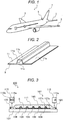
- FIG. 1 is a schematic perspective view of an aircraft 1.
- the aircraft 1 includes main wings 3, horizontal stabilizers 5, and a vertical stabilizer 7.
- the main wings 3, the horizontal stabilizers 5, and the vertical stabilizer 7 may be simply referred to as wings.
- FIG. 2 is a perspective view illustrating a cross section of a part of the wings of the aircraft 1.
- the wings of the aircraft 1 include a skin 9 and a stringer 11.
- the skin 9 is an outer shell of the wings of the aircraft 1.
- the skin 9 has, for example, a flat plate shape.
- the stringer 11 is used as a reinforced material that reinforces the skin 9, and is attached to the skin 9.
- the stringer 11 includes coupling portions 11a coupled to the skin 9 and a protrusion 11b that protrudes away from the skin 9.
- the coupling portions 11a are closer to the skin 9 than the protrusion 11b.
- the protrusion 11b is farther from the skin 9 than the coupling portions 11a.
- a hollow portion 11c is formed between the protrusion 11b and the skin 9.
- the stringer 11 include a hat stringer having a hat shape and a corrugated stringer having a corrugated shape.
- FIG. 2 illustrates an example in which the stringer 11 is the hat stringer.
- the stringer 11 is not limited thereto.
- the stringer 11 may be the corrugated stringer.
- the corrugated stringer is shaped such that hat stringers shown in FIG. 2 are continuously arranged in the left and right directions in FIG. 2 .
- the skin 9 and the stringer 11 are formed of a composite material such as glass fiber reinforced plastics (GFRP) or carbon fiber reinforced plastics (CFRP).
- the composite materials (for example, the skin 9 and the stringer 11) are molded by a composite material molding device 100 which will be described below.
- FIG. 3 is a view illustrating the composite material molding device 100 according to the embodiment.
- the composite material molding device 100 manufactures the composite materials by the VaRTM technique.
- the composite material molding device 100 includes a molding die 101, a film material 103, seal materials 105, a fiber base material 107, jigs (cores) 109, resin distribution media 111, a resin supply unit 113, and a resin discharge unit 115.
- a space S is formed between the molding die 101 and the film material 103.
- the space S is sealed by the seal materials 105 disposed between the molding die 101 and the film material 103.
- the fiber base material 107, the jigs 109, and the resin distribution media 111 are disposed in the space S.
- the fiber base material 107 is placed on the molding die 101.
- the fiber base material 107 is formed by stacking fiber materials such as glass fibers or carbon fibers.
- the fiber base material 107 includes a fiber base material 107a corresponding to the skin 9 (hereinafter referred to as a skin fiber base material) and a fiber base material 107b corresponding to the stringer 11 (hereinafter referred to as a stringer fiber base material).
- the skin fiber base material 107a has a shape approximate to the shape of the skin 9, and has, for example, a flat plate shape.
- the stringer fiber base material 107b has a shape approximate to the shape of the stringer 11, and has, for example, a corrugated shape.
- the skin fiber base material 107a is placed on the molding die 101, and the stringer fiber base material 107b is placed on the skin fiber base material 107a.
- the jigs 109 are disposed between the skin fiber base material 107a and the stringer fiber base material 107b.
- the jigs 109 have an outer shape approximate to the outer shape of the hollow portion 11c (see FIG. 2 ) formed between the skin 9 and the protrusion 11b of the stringer 11.
- the jigs 109 maintain the shape of the protrusion 11b (see FIG. 2 ) after the stringer 11 is molded. Therefore, the outer shape of each jig 109 is identical with an inner surface shape of the protrusion 11b of the stringer 11.
- the jigs 109 extend in a depth direction in FIG. 3 .
- the jigs 109 are placed on the skin fiber base material 107a, and the stringer fiber base material 107b is placed on the jigs 109. That is, the jigs 109 are disposed between the skin fiber base material 107a and the stringer fiber base material 107b.
- the resin distribution media 111 are placed on the fiber base material 107 (that is, the stringer fiber base material 107b).
- a polyethylene net is used as the resin distribution media 111. Supplied resin is uniformly distributed in the space S via the resin distribution media 111.
- the resin supply unit 113 and the resin discharge unit 115 are coupled to the space S sealed by the seal materials 105.
- the resin supply unit 113 includes a resin supply tank 113a that stores resin.
- the resin supply unit 113 supplies the resin stored in the resin supply tank 113a into the space S.
- the resin discharge unit 115 includes a vacuum pump 115a that suctions air and evacuates the space S, and a resin discharge tank 115b that stores the resin.
- the vacuum pump 115a suctions the air and resin in the space S.
- the resin (that is, surplus resin) suctioned from the space S is discharged to the resin discharge tank 115b.
- the resin is thermosetting resin.
- the resin may be thermoplastic resin.
- the plurality of jigs 109 are disposed along a flowing direction of the resin (hereinafter, referred to as a resin flowing direction).
- a longitudinal direction (that is, an extending direction) of the jigs 109 intersects the resin flowing direction.
- the longitudinal direction of the jigs 109 may be orthogonal to the resin flowing direction.
- the longitudinal direction of the jigs 109 may be parallel to the resin flowing direction.
- a user places the skin fiber base material 107a on the molding die 101, and places the jigs 109 on the skin fiber base material 107a. Further, the user places the stringer fiber base material 107b on the jigs 109, and places the resin distribution media 111 on the stringer fiber base material 107b.
- the user covers the resin distribution media 111 with the film material 103, and provides the sealing materials 105 between the film material 103 and the molding die 101 so as to enclose the resin distribution media 111 and the fiber base material 107. Accordingly, the sealed space S is formed between the film material 103 and the molding die 101, and the resin distribution media 111, the fiber base material 107, and the jigs 109 are accommodated in the space S.
- the user couples the resin supply unit 113 and the resin discharge unit 115 to the space S.
- the resin discharge unit 115 drives the vacuum pump 115a.
- the vacuum pump 115a suctions air in the space S to evacuate the space S.
- the resin stored in the resin supply tank 113a is supplied into the space S.
- the resin supplied into the space S is distributed via the resin distribution media 111 throughout the fiber base material 107.
- the resin distributed via the resin distribution media 111 is first introduced onto the stringer fiber base material 107b.
- the stringer fiber base material 107b is impregnated with the resin distributed via the resin distribution media 111.
- the resin is introduced onto the skin fiber base material 107a.
- the skin fiber base material 107a is impregnated with the resin that passes through the stringer fiber base material 107b.
- a surplus of the resin that impregnates the skin fiber base material 107a and the stringer fiber base material 107b is discharged into the resin discharge tank 115b of the resin discharge unit 115.
- the composite material molding device 100 is heated by a heating device (not illustrated).
- the resin is cured when heated by the heating device (not illustrated).
- the composite materials are integrally molded by curing the resin . That is, the molded composite materials (the skin 9 and the stringer 11) are permanently affixed to each other.
- the jigs 109 form the protrusion 11b of the stringer 11.
- the jigs 109 are pulled out from between the skin 9 and the stringer 11. Accordingly, as illustrated in FIG. 2 , the hollow portion 11c is formed between the skin 9 and the protrusion 11b of the stringer 11.
- the skin 9 and the stringer 11 are formed by impregnating the fiber base material 107 with the resin. If the fiber base material 107 is not sufficiently impregnated with the resin, a part of the molded composite materials may have low rigidity. Therefore, a resin impregnation sensor is provided in the composite material molding device 100. The resin impregnation sensor measures whether the fiber base material 107 is impregnated with the resin.
- a resin impregnation sensor is provided outside the composite material molding device 100.
- the stringer fiber base material 107b is impregnated with the resin from a resin distribution media 111 side towards the jigs 109. Therefore, it is difficult for the resin impregnation sensor of the related art to measure whether the fiber base material 107 is sufficiently impregnated up to the boundary between the stringer fiber base material 107b and the jigs 109 with the resin. That is, the resin impregnation sensor of the related art has poor measurement accuracy in measuring whether the fiber base material 107 is impregnated with the resin.
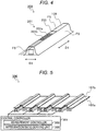
- FIG. 4 is a schematic perspective view of the resin impregnation measurement device 200.
- the resin impregnation measurement device 200 includes the jig 109, a resin impregnation sensor 201, and a mold release member 203.
- the mold release member 203 includes, for example, an insulator.
- the jig 109 includes outer surfaces including facing surfaces FS that are to face the stringer fiber base material 107b (see FIG. 3 ).
- the resin impregnation sensor 201 is disposed on any of the facing surface FS.
- the jig 109 includes outer surfaces including facing surfaces FS that are to face inner surfaces of the protrusion 11b (see FIG. 2 ) of the stringer 11.
- the resin impregnation sensor 201 is disposed on any of the facing surfaces FS.
- the resin impregnation sensor 201 includes a positive electrode 201a and a negative electrode 201b.
- a chain line indicates a power supply line that supplies power to the positive electrode 201a
- a broken line indicates a power supply line that supplies power to the negative electrode 201b.
- the positive electrode 201a and the negative electrode 201b are separated from each other and are disposed in parallel.
- the positive electrode 201a and the negative electrode 201b extend in a longitudinal direction D1 of the jig 109 (that is, a direction intersecting the resin flowing direction).
- the positive electrode 201a and the negative electrode 201b may extend in a short direction D2 of the jig 109 (that is, a direction parallel to the resin flowing direction).
- the positive electrode 201a is disposed on the right side in FIG. 4 and the negative electrode 201b is disposed on the left side in FIG. 4 .
- the disclosure is not limited to this example.
- the positive electrode 201a may be disposed on the left side in FIG. 4
- the negative electrode 201b may be disposed on the right side in FIG. 4 .
- the resin impregnation sensor 201 includes a facing surface that faces the jig 109.
- the facing surface of the resin impregnation sensor 201 is a contact surface of the resin impregnation sensor 201 that is in contact with the jig 109.
- the mold release member 203 is disposed on an opposite side to the facing surface of the resin impregnation sensor 201.
- the mold release member 203 covers the positive electrode 201a and the negative electrode 201b.
- the mold release member 203 prevents the resin from coming into contact with the positive electrode 201a and the negative electrode 201b. Therefore, the positive electrode 201a and the negative electrode 201b are less likely to be caught in the protrusion 11b of the stringer 11 after the composite material is molded.
- the resin impregnation measurement device 200 allows easily removing (pulling out) the positive electrode 201a and the negative electrode 201b from the molded composite materials, together with the jigs 109.
- FIG. 5 is a view illustrating a schematic configuration of a resin impregnation measurement system 300.
- the resin impregnation measurement system 300 includes a plurality of resin impregnation measurement devices 200 and a central controller 301.
- the central controller 301 is implemented by a semiconductor integrated circuit that includes a central processing unit (CPU), a ROM storing programs, a RAM serving as a working area.
- the central controller 301 manages and controls the entire resin impregnation measurement system 300.
- the central controller 301 also functions as a measurement controller 303 and an impregnation ratio deriving unit 305, in cooperation with the programs.
- the measurement controller 303 measures an electrostatic capacity between the positive electrode 201a and the negative electrode 201b (see FIG. 4 ) in each of the resin impregnation measurement devices 200.
- the measurement controller 303 applies a positive voltage to the positive electrode 201a and applies a negative voltage to the negative electrode 201b.
- a potential difference V between the voltage of the positive electrode 201a and the voltage of the negative electrode 201b is, for example, 5V.
- the measurement controller 303 obtains an electrostatic capacity value C 0 based on the dielectric constant ⁇ 0 of vacuum as a measurement result.
- the measurement controller 303 obtains an electrostatic capacity value C S based on the dielectric constant ⁇ S of the resin as a measurement result.
- the measurement controller 303 obtains a value between the value C 0 and the value C S according to the resin filling ratio (that is, an impregnation ratio).
- the electrostatic capacity has a relationship that the value C 0 ⁇ the value C S .
- the electrostatic capacity is measured by applying the positive voltage to the positive electrode 201a and applying the negative voltage to the negative electrode 201b.
- a method for measuring the electrostatic capacity is not limited thereto.
- the resin impregnation sensor 201 may include a pair of electrodes, and the electrostatic capacity may be measured by applying an AC voltage to the pair of electrodes.
- the impregnation ratio deriving unit 305 derives a resin impregnation ratio in the boundary between the fiber base material 107 (that is, the stringer fiber base material 107b) and the jigs 109 based on the electrostatic capacities measured by the measurement controller 303.
- the impregnation ratio deriving unit 305 can derive a resin impregnation ratio in the boundary between the fiber base material 107 and the jigs 109 (in a range of 0% to 100%) based on the electrostatic capacities measured by the measurement controller 303.
- the impregnation ratio deriving unit 305 can know that the filling in the boundary between the fiber base material 107 and the jigs 109 is finished (that is, the impregnation ratio is 100%).
- the resin impregnation measurement device 200 of the embodiment includes the resin impregnation sensors 201 on the jigs 109.
- the impregnation ratio deriving unit 305 can derive the impregnation ratio of the resin in the boundary between the stringer fiber base material 107b and the jigs 109. Therefore, the resin impregnation measurement device 200 of the embodiment can measure whether the fiber base material 107 is sufficiently impregnated up to the boundary between the stringer fiber base material 107b and the jigs 109 with the resin. That is, the resin impregnation measurement device 200 can improve measurement accuracy in measuring whether the fiber base material 107 is impregnated with the resin.
- the resin impregnation measurement device 200 of the embodiment includes the mold release members 203 that cover the resin impregnation sensors 201, on the jigs 109. This configuration allows keeping the resin impregnation sensors 201 separated from the resin. Therefore, the resin impregnation measurement device 200 of the embodiment allows easily removing the resin impregnation sensors 201 from the composite materials after the composite materials are molded.
- the resin impregnation sensors 201 are left in the composite materials (that is, the skin 9 and the stringer 11), there is room for improvement in that a crack might occur in the skin 9 and the stringer 11. That is, if the resin impregnation sensors 201 are left in the composite materials, there is room for improvement in quality of the composite materials.
- the resin impregnation sensors 201 can be easily removed from the composite materials together with the jigs 109. Therefore, the resin impregnation measurement device 200 of the embodiment can prevent cracks from occurring in the composite materials (that is, the skin 9 and the stringer 11) . As a result, a deterioration in quality of the composite materials can be prevented.
- a program that causes a computer to function as the central controller 301 of the resin impregnation measurement system 300, and a storage medium such as a computer readable flexible disk, a magneto-optical disk, a ROM, a CD, a DVD, or a BD that stores the program are provided.
- the program refers to a data processing method described in any language or description method.
- each resin impregnation sensor 201 includes electrodes (that is, the positive electrode 201a and the negative electrode 201b).
- the disclosure is not limited to this example.
- each resin impregnation sensor 201 may be implemented by, for example, an optical fiber sensor.
- an optical fiber is attached to each jig 109 in FIG. 4 .
- the measurement controller 303 causes light to enter from an incident end of each optical fiber, and measures Brillouin scattered light that returns to the incident end.
- the frequency of the Brillouin scattered light is shifted according to the filling ratio (that is, the impregnation ratio) of the resin.
- the impregnation ratio deriving unit 305 derives the impregnation ratio of the resin in the boundary between the stringer fiber base material 107b and the jigs 109 based on the frequency shift of the Brillouin scattered light.
- each resin impregnation sensor 201 is disposed on any of the facing surface FS of the corresponding jig 109 among the outer surfaces of the jig 109.
- the disclosure is not limited to this example.
- each resin impregnation sensor 201 may be disposed, for example, on a facing surface of the corresponding jig 109 that is to face the skin fiber base material 107a (that is, the skin 9) among the outer surfaces of the corresponding jig 109.
- FIG. 6 is a view illustrating a composite material molding device 100A according to a first modification.
- the composite material molding device 100A of the first modification is the same as the composite material molding device 100 of the above embodiment except that the skin fiber base material 107a is the skin 9.
- the skin 9, the jigs 109, the fiber base material 107 (that is, the stringer fiber base material 107b), and the resin distribution media 111 are accommodated in the space S.
- the skin 9 is placed on the molding die 101.
- the jigs 109 and the stringer fiber base material 107b are placed on the skin 9.
- the resin distribution media 111 is placed on the stringer fiber base material 107b. In this state, when the resin is filled and cured in the space S, a composite material (that is the stringer 11) is molded on the skin 9.
- FIG. 7 is a view illustrating a composite material molding device 100B according to a second modification.
- the composite material molding device 100B of the second modification is the same as the composite material molding device 100 of the above embodiment and the composite material molding device 100A of the first modification except that neither the skin fiber base material 107a nor the skin 9 is provided in the space S.
- the jigs 109, the fiber base material 107 that is, the stringer fiber base material 107b
- the resin distribution media 111 are accommodated in the space S.
- the jigs 109 and the stringer fiber base material 107b are placed on the molding die 101.
- the resin distribution media 111 is placed on the stringer fiber base material 107b. In this state, when the resin is filled and cured in the space S, a composite material (that is, the stringer 11) is molded on the molding die 101.
Landscapes
- Engineering & Computer Science (AREA)
- Mechanical Engineering (AREA)
- Physics & Mathematics (AREA)
- Power Engineering (AREA)
- Composite Materials (AREA)
- Chemical & Material Sciences (AREA)
- Thermal Sciences (AREA)
- Fluid Mechanics (AREA)
- General Physics & Mathematics (AREA)
- Electromagnetism (AREA)
- Architecture (AREA)
- Civil Engineering (AREA)
- Structural Engineering (AREA)
- Moulding By Coating Moulds (AREA)
- Reinforced Plastic Materials (AREA)
Applications Claiming Priority (1)
| Application Number | Priority Date | Filing Date | Title |
|---|---|---|---|
| JP2018246725A JP7161399B2 (ja) | 2018-12-28 | 2018-12-28 | 樹脂含浸測定装置 |
Publications (2)
| Publication Number | Publication Date |
|---|---|
| EP3674069A1 true EP3674069A1 (de) | 2020-07-01 |
| EP3674069B1 EP3674069B1 (de) | 2021-09-15 |
Family
ID=68583188
Family Applications (1)
| Application Number | Title | Priority Date | Filing Date |
|---|---|---|---|
| EP19209434.0A Active EP3674069B1 (de) | 2018-12-28 | 2019-11-15 | Harzimprägnierungsmessvorrichtung |
Country Status (4)
| Country | Link |
|---|---|
| US (1) | US11623374B2 (de) |
| EP (1) | EP3674069B1 (de) |
| JP (1) | JP7161399B2 (de) |
| CN (1) | CN111376501B (de) |
Families Citing this family (2)
| Publication number | Priority date | Publication date | Assignee | Title |
|---|---|---|---|---|
| ES2925907T3 (es) * | 2019-07-03 | 2022-10-20 | Airbus Operations Slu | Sistema para monitorización de flujo de resina |
| JP2025030426A (ja) | 2023-08-23 | 2025-03-07 | 三菱重工業株式会社 | 検査装置、及び検査システム |
Citations (4)
| Publication number | Priority date | Publication date | Assignee | Title |
|---|---|---|---|---|
| EP1415782A1 (de) * | 2001-08-07 | 2004-05-06 | Toray Industries, Inc. | Verfahren zur herstellung eines vergrösserten glieds aus faserverstärktem kunststoff |
| JP2013075471A (ja) | 2011-09-30 | 2013-04-25 | Toray Ind Inc | 繊維強化プラスチック構造体の成形方法および装置 |
| US20140290840A1 (en) * | 2011-07-27 | 2014-10-02 | Heinz Bardenhagen | Device for the manufacture of a bonded component from fibre-reinforced plastics and also a method |
| US20140300021A1 (en) * | 2011-07-27 | 2014-10-09 | Airbus Operations Gmbh | Device for the manufacture of a bonded component from fibre-reinforced plastics and also a method |
Family Cites Families (43)
| Publication number | Priority date | Publication date | Assignee | Title |
|---|---|---|---|---|
| US2435866A (en) * | 1943-07-30 | 1948-02-10 | Paul H Bilhuber | Fluid-operated apparatus for producing molded articles |
| US4044600A (en) * | 1972-01-31 | 1977-08-30 | The Firestone Tire & Rubber Company | Tire cure and heat transfer simulator |
| US4486996A (en) * | 1982-05-19 | 1984-12-11 | Luis Alejos | Construction-panel prefabrication method, panels thus made and equipment for implementing said method |
| US5453291A (en) * | 1993-05-25 | 1995-09-26 | Honda Giken Kogyo Kabushiki Kaisha | FRP member and method of detecting internal damage therein |
| US5770155A (en) * | 1995-11-21 | 1998-06-23 | United Technologies Corporation | Composite structure resin cure monitoring apparatus using an optical fiber grating sensor |
| US6532799B2 (en) * | 2000-01-18 | 2003-03-18 | Florida State University Research Foundation | System for in-situ and on-line monitoring of a perform layup process for liquid composite molding |
| JP4727960B2 (ja) * | 2004-09-06 | 2011-07-20 | 株式会社プライムポリマー | 繊維強化樹脂組成物の製造方法 |
| JP4676735B2 (ja) * | 2004-09-22 | 2011-04-27 | 東レ・ダウコーニング株式会社 | 光半導体装置の製造方法および光半導体装置 |
| EP2368700B1 (de) * | 2005-07-05 | 2013-06-19 | Quickstep Technologies Pty, Ltd. | Produktionssystem, umfassend Vibrationsmittel und Druckgaszuführung zur Herstellung eines Verbundbauteils |
| GB0622691D0 (en) * | 2006-11-14 | 2006-12-27 | Airbus Uk Ltd | Method and apparatus for controlling the geometry of a composite component |
| JP2008137179A (ja) * | 2006-11-30 | 2008-06-19 | Toray Ind Inc | 繊維強化プラスチックの製造方法 |
| DE102007015909A1 (de) * | 2007-04-02 | 2008-10-09 | Mt Aerospace Ag | Verfahren zur Herstellung faserverstärkter Hohlkörper |
| US7861969B2 (en) * | 2007-05-24 | 2011-01-04 | The Boeing Company | Shaped composite stringers and methods of making |
| JP5151269B2 (ja) | 2007-06-26 | 2013-02-27 | 横浜ゴム株式会社 | 繊維強化プラスチックパネルの製造方法および製造装置 |
| US7879276B2 (en) * | 2007-11-08 | 2011-02-01 | The Boeing Company | Foam stiffened hollow composite stringer |
| US8196452B2 (en) * | 2008-03-27 | 2012-06-12 | The Boeing Company | Collection of process data using in-situ sensors |
| US8617687B2 (en) * | 2009-08-03 | 2013-12-31 | The Boeing Company | Multi-functional aircraft structures |
| DE102009029575B4 (de) * | 2009-09-18 | 2011-06-22 | Airbus Operations GmbH, 21129 | Verfahren zur Versteifung eines Faserverbundbauteils und Anordnung zur Herstellung eines versteiften Faserverbundteils |
| US8703268B2 (en) * | 2009-11-13 | 2014-04-22 | The Boeing Company | Morphing panel structure |
| US8556618B2 (en) * | 2011-04-07 | 2013-10-15 | Spirit Aerosystems, Inc. | Method and bladder apparatus for forming composite parts |
| US9969131B2 (en) * | 2011-06-22 | 2018-05-15 | The Boeing Company | Automated ply layup system |
| JP2013022835A (ja) * | 2011-07-21 | 2013-02-04 | Mitsubishi Heavy Ind Ltd | 繊維強化樹脂を備える製品を少なくとも2つ製造する方法および装置 |
| US9056413B1 (en) * | 2012-06-07 | 2015-06-16 | The Boeing Company | Method and portable station for laying up and curing composite resin parts |
| EP2671708B1 (de) * | 2012-06-08 | 2017-02-01 | Airbus Operations GmbH | Verfahren und System zur Leckerkennung beim Vakuumverpacken |
| GB201215124D0 (en) * | 2012-08-24 | 2012-10-10 | Newton John R | A method of making a composite structure |
| JP5738816B2 (ja) * | 2012-09-13 | 2015-06-24 | 住友ゴム工業株式会社 | ゴムシート製造装置およびゴムシート取上げ装置 |
| US10239265B2 (en) * | 2013-03-15 | 2019-03-26 | Composites Intellectual Holdings, Inc. | Structural composite preform wet-out and curing system and method |
| CN108724550B (zh) * | 2013-11-07 | 2020-07-31 | Agc株式会社 | 脱模膜、以及半导体封装体的制造方法 |
| WO2016003339A1 (en) * | 2014-07-03 | 2016-01-07 | Saab Ab | A composite article having multifunctional properties and method for its manufacture |
| JP6598477B2 (ja) * | 2015-03-11 | 2019-10-30 | 株式会社Subaru | 複合材の成形装置及び複合材の成形方法 |
| US10300634B2 (en) * | 2015-11-16 | 2019-05-28 | The Boeing Company | Advanced multiple grid heat sources to achieve optimized cure structure and method of making the same |
| CA3007598A1 (en) * | 2015-12-17 | 2017-06-22 | Bombardier Inc. | Preform tool and method of shaping composite material |
| JP6346214B2 (ja) * | 2016-03-24 | 2018-06-20 | 株式会社Subaru | 複合材成形治具、複合材成形方法、超音波検査システム、超音波検査方法及び航空機構造体 |
| DE102016210086B4 (de) | 2016-06-08 | 2025-11-13 | Airbus Operations Gmbh | Verfahren zum Herstellen eines Strukturbauteils für ein Luft- oder Raumfahrzeug, sowie Anordnung |
| WO2018051445A1 (ja) * | 2016-09-14 | 2018-03-22 | 日産自動車株式会社 | 複合材料の成形方法および複合材料 |
| IT201600093472A1 (it) * | 2016-09-16 | 2018-03-16 | Afros Spa | Metodo ed apparato di infusione per la produzione di corpi in materiale composito rinforzato |
| FR3056141A1 (fr) * | 2016-09-20 | 2018-03-23 | Airbus Operations (S.A.S.) | Procede de fabrication d'une piece en materiau composite |
| CN109562578B (zh) | 2016-09-29 | 2020-12-08 | 株式会社斯巴鲁 | 复合材料结构体和复合材料结构体的制造方法 |
| KR20180071751A (ko) * | 2016-12-20 | 2018-06-28 | 주식회사 효성 | 수지 함침 속도 측정 장치 |
| EP3489001B1 (de) * | 2017-11-22 | 2025-08-06 | Afros S.P.A. | Vorrichtung zur fein- und gesteuerten einstellung eines spritzgiessverfahrens und zugehöriges industrieverfahren |
| DE102018206665A1 (de) * | 2018-04-30 | 2019-10-31 | Airbus Operations Gmbh | Strukturbauteil sowie System und Verfahren zur Detektion von Beschädigungen |
| JP7202258B2 (ja) | 2018-09-03 | 2023-01-11 | 株式会社Subaru | 樹脂含浸測定システム |
| CN110873737B (zh) * | 2018-09-03 | 2024-04-26 | 株式会社斯巴鲁 | 树脂含浸测定系统 |
-
2018
- 2018-12-28 JP JP2018246725A patent/JP7161399B2/ja active Active
-
2019
- 2019-11-13 CN CN201911107840.7A patent/CN111376501B/zh active Active
- 2019-11-15 EP EP19209434.0A patent/EP3674069B1/de active Active
- 2019-12-18 US US16/718,406 patent/US11623374B2/en active Active
Patent Citations (4)
| Publication number | Priority date | Publication date | Assignee | Title |
|---|---|---|---|---|
| EP1415782A1 (de) * | 2001-08-07 | 2004-05-06 | Toray Industries, Inc. | Verfahren zur herstellung eines vergrösserten glieds aus faserverstärktem kunststoff |
| US20140290840A1 (en) * | 2011-07-27 | 2014-10-02 | Heinz Bardenhagen | Device for the manufacture of a bonded component from fibre-reinforced plastics and also a method |
| US20140300021A1 (en) * | 2011-07-27 | 2014-10-09 | Airbus Operations Gmbh | Device for the manufacture of a bonded component from fibre-reinforced plastics and also a method |
| JP2013075471A (ja) | 2011-09-30 | 2013-04-25 | Toray Ind Inc | 繊維強化プラスチック構造体の成形方法および装置 |
Also Published As
| Publication number | Publication date |
|---|---|
| US11623374B2 (en) | 2023-04-11 |
| EP3674069B1 (de) | 2021-09-15 |
| JP7161399B2 (ja) | 2022-10-26 |
| CN111376501A (zh) | 2020-07-07 |
| US20200207037A1 (en) | 2020-07-02 |
| CN111376501B (zh) | 2023-10-27 |
| JP2020104443A (ja) | 2020-07-09 |
Similar Documents
| Publication | Publication Date | Title |
|---|---|---|
| EP3476578B1 (de) | Formvorrichtung für verbundmaterial und verbundformverfahren | |
| EP3674069B1 (de) | Harzimprägnierungsmessvorrichtung | |
| KR102266130B1 (ko) | 복합재 구조물을 위한 만곡부 필러, 만곡부 필러를 포함하는 복합재 구조물, 및 그를 형성하는 시스템 및 방법 | |
| JP7111483B2 (ja) | 複雑な表面への対象物の柔軟な真空固定 | |
| US9108376B2 (en) | Method for making a wind turbine rotor blade half shell or wind turbine rotor blade and production mold therefor | |
| EP2093043B2 (de) | Verfahren und Vorrichtung zur Entdeckung eines Lecks in einem VARTM-Prozess | |
| US8460502B2 (en) | Method and tooling for manufacture of co-cured composite structures | |
| US9623620B2 (en) | Three-dimensional reuseable curing caul for use in curing integrated composite components and methods of making the same | |
| US9067345B2 (en) | Mold for manufacture of fiber composite parts and method of manufacture of fiber composite parts with such a mold | |
| US10479032B2 (en) | Method of fabricating a vacuum barrier system | |
| WO2014070381A1 (en) | System and method for manufacturing monolithic structures using expanding internal tools | |
| CN104149228B (zh) | 一种玻璃钢天线罩的一体化成型模具及成型方法 | |
| EP2949458A1 (de) | Verfahren zur Herstellung von mit Omega-Stringern verstärkten Kohlefaserplatten | |
| US20110206875A1 (en) | Method and arrangement for production of an integral hollow-profiled component with fibre composite material | |
| US20170129195A1 (en) | Edge breathers for composite products | |
| US20190366653A1 (en) | 3d printed end cauls for composite part fabrication | |
| US20220152881A1 (en) | Multi-Segment Mandrel for Processing a Composite Part and Method for Fabricating a Composite Part | |
| US10882263B2 (en) | Method for impregnating a preform with resin utilizing a caul plate having a channel for distributing resin | |
| EP3616891B1 (de) | Harzimprägniermesssystem | |
| JP7202258B2 (ja) | 樹脂含浸測定システム | |
| US11828730B2 (en) | Vacuum bag having integral ultrasonic transducers | |
| US20200238633A1 (en) | Production method of composite material | |
| KR102075425B1 (ko) | 헬리콥터의 수평 꼬리날개 제조 장치 및 방법 | |
| CN114536814A (zh) | 用于飞行器制造的隔板系统 |
Legal Events
| Date | Code | Title | Description |
|---|---|---|---|
| PUAI | Public reference made under article 153(3) epc to a published international application that has entered the european phase |
Free format text: ORIGINAL CODE: 0009012 |
|
| STAA | Information on the status of an ep patent application or granted ep patent |
Free format text: STATUS: THE APPLICATION HAS BEEN PUBLISHED |
|
| AK | Designated contracting states |
Kind code of ref document: A1 Designated state(s): AL AT BE BG CH CY CZ DE DK EE ES FI FR GB GR HR HU IE IS IT LI LT LU LV MC MK MT NL NO PL PT RO RS SE SI SK SM TR |
|
| AX | Request for extension of the european patent |
Extension state: BA ME |
|
| STAA | Information on the status of an ep patent application or granted ep patent |
Free format text: STATUS: REQUEST FOR EXAMINATION WAS MADE |
|
| 17P | Request for examination filed |
Effective date: 20201223 |
|
| RBV | Designated contracting states (corrected) |
Designated state(s): AL AT BE BG CH CY CZ DE DK EE ES FI FR GB GR HR HU IE IS IT LI LT LU LV MC MK MT NL NO PL PT RO RS SE SI SK SM TR |
|
| GRAP | Despatch of communication of intention to grant a patent |
Free format text: ORIGINAL CODE: EPIDOSNIGR1 |
|
| STAA | Information on the status of an ep patent application or granted ep patent |
Free format text: STATUS: GRANT OF PATENT IS INTENDED |
|
| INTG | Intention to grant announced |
Effective date: 20210528 |
|
| GRAS | Grant fee paid |
Free format text: ORIGINAL CODE: EPIDOSNIGR3 |
|
| GRAA | (expected) grant |
Free format text: ORIGINAL CODE: 0009210 |
|
| STAA | Information on the status of an ep patent application or granted ep patent |
Free format text: STATUS: THE PATENT HAS BEEN GRANTED |
|
| AK | Designated contracting states |
Kind code of ref document: B1 Designated state(s): AL AT BE BG CH CY CZ DE DK EE ES FI FR GB GR HR HU IE IS IT LI LT LU LV MC MK MT NL NO PL PT RO RS SE SI SK SM TR |
|
| REG | Reference to a national code |
Ref country code: CH Ref legal event code: EP |
|
| REG | Reference to a national code |
Ref country code: DE Ref legal event code: R096 Ref document number: 602019007707 Country of ref document: DE |
|
| REG | Reference to a national code |
Ref country code: IE Ref legal event code: FG4D |
|
| REG | Reference to a national code |
Ref country code: AT Ref legal event code: REF Ref document number: 1430205 Country of ref document: AT Kind code of ref document: T Effective date: 20211015 |
|
| REG | Reference to a national code |
Ref country code: LT Ref legal event code: MG9D |
|
| REG | Reference to a national code |
Ref country code: NL Ref legal event code: MP Effective date: 20210915 |
|
| PG25 | Lapsed in a contracting state [announced via postgrant information from national office to epo] |
Ref country code: HR Free format text: LAPSE BECAUSE OF FAILURE TO SUBMIT A TRANSLATION OF THE DESCRIPTION OR TO PAY THE FEE WITHIN THE PRESCRIBED TIME-LIMIT Effective date: 20210915 Ref country code: FI Free format text: LAPSE BECAUSE OF FAILURE TO SUBMIT A TRANSLATION OF THE DESCRIPTION OR TO PAY THE FEE WITHIN THE PRESCRIBED TIME-LIMIT Effective date: 20210915 Ref country code: NO Free format text: LAPSE BECAUSE OF FAILURE TO SUBMIT A TRANSLATION OF THE DESCRIPTION OR TO PAY THE FEE WITHIN THE PRESCRIBED TIME-LIMIT Effective date: 20211215 Ref country code: LT Free format text: LAPSE BECAUSE OF FAILURE TO SUBMIT A TRANSLATION OF THE DESCRIPTION OR TO PAY THE FEE WITHIN THE PRESCRIBED TIME-LIMIT Effective date: 20210915 Ref country code: BG Free format text: LAPSE BECAUSE OF FAILURE TO SUBMIT A TRANSLATION OF THE DESCRIPTION OR TO PAY THE FEE WITHIN THE PRESCRIBED TIME-LIMIT Effective date: 20211215 Ref country code: SE Free format text: LAPSE BECAUSE OF FAILURE TO SUBMIT A TRANSLATION OF THE DESCRIPTION OR TO PAY THE FEE WITHIN THE PRESCRIBED TIME-LIMIT Effective date: 20210915 Ref country code: RS Free format text: LAPSE BECAUSE OF FAILURE TO SUBMIT A TRANSLATION OF THE DESCRIPTION OR TO PAY THE FEE WITHIN THE PRESCRIBED TIME-LIMIT Effective date: 20210915 |
|
| REG | Reference to a national code |
Ref country code: AT Ref legal event code: MK05 Ref document number: 1430205 Country of ref document: AT Kind code of ref document: T Effective date: 20210915 |
|
| PG25 | Lapsed in a contracting state [announced via postgrant information from national office to epo] |
Ref country code: LV Free format text: LAPSE BECAUSE OF FAILURE TO SUBMIT A TRANSLATION OF THE DESCRIPTION OR TO PAY THE FEE WITHIN THE PRESCRIBED TIME-LIMIT Effective date: 20210915 Ref country code: GR Free format text: LAPSE BECAUSE OF FAILURE TO SUBMIT A TRANSLATION OF THE DESCRIPTION OR TO PAY THE FEE WITHIN THE PRESCRIBED TIME-LIMIT Effective date: 20211216 |
|
| PG25 | Lapsed in a contracting state [announced via postgrant information from national office to epo] |
Ref country code: AT Free format text: LAPSE BECAUSE OF FAILURE TO SUBMIT A TRANSLATION OF THE DESCRIPTION OR TO PAY THE FEE WITHIN THE PRESCRIBED TIME-LIMIT Effective date: 20210915 |
|
| PG25 | Lapsed in a contracting state [announced via postgrant information from national office to epo] |
Ref country code: IS Free format text: LAPSE BECAUSE OF FAILURE TO SUBMIT A TRANSLATION OF THE DESCRIPTION OR TO PAY THE FEE WITHIN THE PRESCRIBED TIME-LIMIT Effective date: 20220115 Ref country code: SM Free format text: LAPSE BECAUSE OF FAILURE TO SUBMIT A TRANSLATION OF THE DESCRIPTION OR TO PAY THE FEE WITHIN THE PRESCRIBED TIME-LIMIT Effective date: 20210915 Ref country code: SK Free format text: LAPSE BECAUSE OF FAILURE TO SUBMIT A TRANSLATION OF THE DESCRIPTION OR TO PAY THE FEE WITHIN THE PRESCRIBED TIME-LIMIT Effective date: 20210915 Ref country code: RO Free format text: LAPSE BECAUSE OF FAILURE TO SUBMIT A TRANSLATION OF THE DESCRIPTION OR TO PAY THE FEE WITHIN THE PRESCRIBED TIME-LIMIT Effective date: 20210915 Ref country code: PT Free format text: LAPSE BECAUSE OF FAILURE TO SUBMIT A TRANSLATION OF THE DESCRIPTION OR TO PAY THE FEE WITHIN THE PRESCRIBED TIME-LIMIT Effective date: 20220117 Ref country code: PL Free format text: LAPSE BECAUSE OF FAILURE TO SUBMIT A TRANSLATION OF THE DESCRIPTION OR TO PAY THE FEE WITHIN THE PRESCRIBED TIME-LIMIT Effective date: 20210915 Ref country code: NL Free format text: LAPSE BECAUSE OF FAILURE TO SUBMIT A TRANSLATION OF THE DESCRIPTION OR TO PAY THE FEE WITHIN THE PRESCRIBED TIME-LIMIT Effective date: 20210915 Ref country code: ES Free format text: LAPSE BECAUSE OF FAILURE TO SUBMIT A TRANSLATION OF THE DESCRIPTION OR TO PAY THE FEE WITHIN THE PRESCRIBED TIME-LIMIT Effective date: 20210915 Ref country code: EE Free format text: LAPSE BECAUSE OF FAILURE TO SUBMIT A TRANSLATION OF THE DESCRIPTION OR TO PAY THE FEE WITHIN THE PRESCRIBED TIME-LIMIT Effective date: 20210915 Ref country code: CZ Free format text: LAPSE BECAUSE OF FAILURE TO SUBMIT A TRANSLATION OF THE DESCRIPTION OR TO PAY THE FEE WITHIN THE PRESCRIBED TIME-LIMIT Effective date: 20210915 Ref country code: AL Free format text: LAPSE BECAUSE OF FAILURE TO SUBMIT A TRANSLATION OF THE DESCRIPTION OR TO PAY THE FEE WITHIN THE PRESCRIBED TIME-LIMIT Effective date: 20210915 |
|
| REG | Reference to a national code |
Ref country code: DE Ref legal event code: R097 Ref document number: 602019007707 Country of ref document: DE |
|
| PG25 | Lapsed in a contracting state [announced via postgrant information from national office to epo] |
Ref country code: MC Free format text: LAPSE BECAUSE OF FAILURE TO SUBMIT A TRANSLATION OF THE DESCRIPTION OR TO PAY THE FEE WITHIN THE PRESCRIBED TIME-LIMIT Effective date: 20210915 |
|
| PLBE | No opposition filed within time limit |
Free format text: ORIGINAL CODE: 0009261 |
|
| STAA | Information on the status of an ep patent application or granted ep patent |
Free format text: STATUS: NO OPPOSITION FILED WITHIN TIME LIMIT |
|
| PG25 | Lapsed in a contracting state [announced via postgrant information from national office to epo] |
Ref country code: LU Free format text: LAPSE BECAUSE OF NON-PAYMENT OF DUE FEES Effective date: 20211115 Ref country code: DK Free format text: LAPSE BECAUSE OF FAILURE TO SUBMIT A TRANSLATION OF THE DESCRIPTION OR TO PAY THE FEE WITHIN THE PRESCRIBED TIME-LIMIT Effective date: 20210915 Ref country code: BE Free format text: LAPSE BECAUSE OF NON-PAYMENT OF DUE FEES Effective date: 20211130 |
|
| REG | Reference to a national code |
Ref country code: BE Ref legal event code: MM Effective date: 20211130 |
|
| 26N | No opposition filed |
Effective date: 20220616 |
|
| PG25 | Lapsed in a contracting state [announced via postgrant information from national office to epo] |
Ref country code: SI Free format text: LAPSE BECAUSE OF FAILURE TO SUBMIT A TRANSLATION OF THE DESCRIPTION OR TO PAY THE FEE WITHIN THE PRESCRIBED TIME-LIMIT Effective date: 20210915 |
|
| PG25 | Lapsed in a contracting state [announced via postgrant information from national office to epo] |
Ref country code: IE Free format text: LAPSE BECAUSE OF NON-PAYMENT OF DUE FEES Effective date: 20211115 |
|
| PG25 | Lapsed in a contracting state [announced via postgrant information from national office to epo] |
Ref country code: IT Free format text: LAPSE BECAUSE OF FAILURE TO SUBMIT A TRANSLATION OF THE DESCRIPTION OR TO PAY THE FEE WITHIN THE PRESCRIBED TIME-LIMIT Effective date: 20210915 |
|
| PG25 | Lapsed in a contracting state [announced via postgrant information from national office to epo] |
Ref country code: CY Free format text: LAPSE BECAUSE OF FAILURE TO SUBMIT A TRANSLATION OF THE DESCRIPTION OR TO PAY THE FEE WITHIN THE PRESCRIBED TIME-LIMIT Effective date: 20210915 |
|
| REG | Reference to a national code |
Ref country code: CH Ref legal event code: PL |
|
| PG25 | Lapsed in a contracting state [announced via postgrant information from national office to epo] |
Ref country code: LI Free format text: LAPSE BECAUSE OF NON-PAYMENT OF DUE FEES Effective date: 20221130 Ref country code: HU Free format text: LAPSE BECAUSE OF FAILURE TO SUBMIT A TRANSLATION OF THE DESCRIPTION OR TO PAY THE FEE WITHIN THE PRESCRIBED TIME-LIMIT; INVALID AB INITIO Effective date: 20191115 Ref country code: CH Free format text: LAPSE BECAUSE OF NON-PAYMENT OF DUE FEES Effective date: 20221130 |
|
| PG25 | Lapsed in a contracting state [announced via postgrant information from national office to epo] |
Ref country code: MK Free format text: LAPSE BECAUSE OF FAILURE TO SUBMIT A TRANSLATION OF THE DESCRIPTION OR TO PAY THE FEE WITHIN THE PRESCRIBED TIME-LIMIT Effective date: 20210915 |
|
| PG25 | Lapsed in a contracting state [announced via postgrant information from national office to epo] |
Ref country code: TR Free format text: LAPSE BECAUSE OF FAILURE TO SUBMIT A TRANSLATION OF THE DESCRIPTION OR TO PAY THE FEE WITHIN THE PRESCRIBED TIME-LIMIT Effective date: 20210915 |
|
| GBPC | Gb: european patent ceased through non-payment of renewal fee |
Effective date: 20231115 |
|
| PG25 | Lapsed in a contracting state [announced via postgrant information from national office to epo] |
Ref country code: MT Free format text: LAPSE BECAUSE OF FAILURE TO SUBMIT A TRANSLATION OF THE DESCRIPTION OR TO PAY THE FEE WITHIN THE PRESCRIBED TIME-LIMIT Effective date: 20210915 |
|
| PG25 | Lapsed in a contracting state [announced via postgrant information from national office to epo] |
Ref country code: GB Free format text: LAPSE BECAUSE OF NON-PAYMENT OF DUE FEES Effective date: 20231115 |
|
| PG25 | Lapsed in a contracting state [announced via postgrant information from national office to epo] |
Ref country code: GB Free format text: LAPSE BECAUSE OF NON-PAYMENT OF DUE FEES Effective date: 20231115 |
|
| PGFP | Annual fee paid to national office [announced via postgrant information from national office to epo] |
Ref country code: DE Payment date: 20251119 Year of fee payment: 7 |
|
| PGFP | Annual fee paid to national office [announced via postgrant information from national office to epo] |
Ref country code: FR Payment date: 20251126 Year of fee payment: 7 |