EP3674045A1 - System zur extrusion von baumaterialsträngen für roboter zur additiven fertigung von architektonischen strukturen, das eine verflüssigungsvorrichtung des extrudierten zementmaterials umfasst - Google Patents
System zur extrusion von baumaterialsträngen für roboter zur additiven fertigung von architektonischen strukturen, das eine verflüssigungsvorrichtung des extrudierten zementmaterials umfasst Download PDFInfo
- Publication number
- EP3674045A1 EP3674045A1 EP19207626.3A EP19207626A EP3674045A1 EP 3674045 A1 EP3674045 A1 EP 3674045A1 EP 19207626 A EP19207626 A EP 19207626A EP 3674045 A1 EP3674045 A1 EP 3674045A1
- Authority
- EP
- European Patent Office
- Prior art keywords
- extrusion
- cords
- extrusion head
- bead
- extruded
- Prior art date
- Legal status (The legal status is an assumption and is not a legal conclusion. Google has not performed a legal analysis and makes no representation as to the accuracy of the status listed.)
- Granted
Links
- 238000001125 extrusion Methods 0.000 title claims abstract description 151
- 239000011324 bead Substances 0.000 title claims abstract description 102
- 239000000654 additive Substances 0.000 title claims abstract description 29
- 238000004519 manufacturing process Methods 0.000 title claims abstract description 29
- 230000000996 additive effect Effects 0.000 title claims abstract description 25
- 239000000463 material Substances 0.000 title claims description 37
- 239000004035 construction material Substances 0.000 title claims description 32
- 239000004568 cement Substances 0.000 title description 3
- 239000004566 building material Substances 0.000 claims abstract description 34
- 238000005243 fluidization Methods 0.000 claims abstract description 17
- 238000003860 storage Methods 0.000 claims description 19
- 238000000034 method Methods 0.000 claims description 15
- 239000012530 fluid Substances 0.000 claims description 9
- 239000002671 adjuvant Substances 0.000 claims description 7
- 238000006073 displacement reaction Methods 0.000 claims description 5
- 230000007246 mechanism Effects 0.000 claims description 5
- 238000002604 ultrasonography Methods 0.000 claims description 3
- 238000010276 construction Methods 0.000 description 18
- 238000007639 printing Methods 0.000 description 7
- 239000003795 chemical substances by application Substances 0.000 description 6
- 238000011144 upstream manufacturing Methods 0.000 description 5
- 238000010146 3D printing Methods 0.000 description 4
- 235000021183 entrée Nutrition 0.000 description 3
- 230000008569 process Effects 0.000 description 3
- 230000000593 degrading effect Effects 0.000 description 2
- 230000000704 physical effect Effects 0.000 description 2
- 238000005086 pumping Methods 0.000 description 2
- 238000000518 rheometry Methods 0.000 description 2
- 238000013019 agitation Methods 0.000 description 1
- 230000008859 change Effects 0.000 description 1
- 230000008021 deposition Effects 0.000 description 1
- 238000005516 engineering process Methods 0.000 description 1
- 239000010419 fine particle Substances 0.000 description 1
- 238000003304 gavage Methods 0.000 description 1
- 239000008240 homogeneous mixture Substances 0.000 description 1
- 239000000203 mixture Substances 0.000 description 1
- 230000002572 peristaltic effect Effects 0.000 description 1
- 239000011505 plaster Substances 0.000 description 1
- 230000010349 pulsation Effects 0.000 description 1
- 230000009467 reduction Effects 0.000 description 1
- 230000002787 reinforcement Effects 0.000 description 1
- 238000010008 shearing Methods 0.000 description 1
- 239000004094 surface-active agent Substances 0.000 description 1
- 230000001360 synchronised effect Effects 0.000 description 1
Images


Classifications
-
- B—PERFORMING OPERATIONS; TRANSPORTING
- B28—WORKING CEMENT, CLAY, OR STONE
- B28B—SHAPING CLAY OR OTHER CERAMIC COMPOSITIONS; SHAPING SLAG; SHAPING MIXTURES CONTAINING CEMENTITIOUS MATERIAL, e.g. PLASTER
- B28B1/00—Producing shaped prefabricated articles from the material
- B28B1/001—Rapid manufacturing of 3D objects by additive depositing, agglomerating or laminating of material
-
- B—PERFORMING OPERATIONS; TRANSPORTING
- B28—WORKING CEMENT, CLAY, OR STONE
- B28B—SHAPING CLAY OR OTHER CERAMIC COMPOSITIONS; SHAPING SLAG; SHAPING MIXTURES CONTAINING CEMENTITIOUS MATERIAL, e.g. PLASTER
- B28B1/00—Producing shaped prefabricated articles from the material
- B28B1/08—Producing shaped prefabricated articles from the material by vibrating or jolting
- B28B1/093—Producing shaped prefabricated articles from the material by vibrating or jolting by means directly acting on the material, e.g. by cores wholly or partly immersed in the material or elements acting on the upper surface of the material
- B28B1/0935—Producing shaped prefabricated articles from the material by vibrating or jolting by means directly acting on the material, e.g. by cores wholly or partly immersed in the material or elements acting on the upper surface of the material using only elements wholly or partly immersed in the material, e.g. cores
-
- B—PERFORMING OPERATIONS; TRANSPORTING
- B28—WORKING CEMENT, CLAY, OR STONE
- B28B—SHAPING CLAY OR OTHER CERAMIC COMPOSITIONS; SHAPING SLAG; SHAPING MIXTURES CONTAINING CEMENTITIOUS MATERIAL, e.g. PLASTER
- B28B3/00—Producing shaped articles from the material by using presses; Presses specially adapted therefor
- B28B3/20—Producing shaped articles from the material by using presses; Presses specially adapted therefor wherein the material is extruded
-
- B—PERFORMING OPERATIONS; TRANSPORTING
- B33—ADDITIVE MANUFACTURING TECHNOLOGY
- B33Y—ADDITIVE MANUFACTURING, i.e. MANUFACTURING OF THREE-DIMENSIONAL [3-D] OBJECTS BY ADDITIVE DEPOSITION, ADDITIVE AGGLOMERATION OR ADDITIVE LAYERING, e.g. BY 3-D PRINTING, STEREOLITHOGRAPHY OR SELECTIVE LASER SINTERING
- B33Y10/00—Processes of additive manufacturing
-
- B—PERFORMING OPERATIONS; TRANSPORTING
- B33—ADDITIVE MANUFACTURING TECHNOLOGY
- B33Y—ADDITIVE MANUFACTURING, i.e. MANUFACTURING OF THREE-DIMENSIONAL [3-D] OBJECTS BY ADDITIVE DEPOSITION, ADDITIVE AGGLOMERATION OR ADDITIVE LAYERING, e.g. BY 3-D PRINTING, STEREOLITHOGRAPHY OR SELECTIVE LASER SINTERING
- B33Y30/00—Apparatus for additive manufacturing; Details thereof or accessories therefor
-
- E—FIXED CONSTRUCTIONS
- E04—BUILDING
- E04G—SCAFFOLDING; FORMS; SHUTTERING; BUILDING IMPLEMENTS OR AIDS, OR THEIR USE; HANDLING BUILDING MATERIALS ON THE SITE; REPAIRING, BREAKING-UP OR OTHER WORK ON EXISTING BUILDINGS
- E04G21/00—Preparing, conveying, or working-up building materials or building elements in situ; Other devices or measures for constructional work
- E04G21/02—Conveying or working-up concrete or similar masses able to be heaped or cast
- E04G21/04—Devices for both conveying and distributing
- E04G21/0418—Devices for both conveying and distributing with distribution hose
- E04G21/0427—Devices for both conveying and distributing with distribution hose on a static support, e.g. crane
-
- E—FIXED CONSTRUCTIONS
- E04—BUILDING
- E04G—SCAFFOLDING; FORMS; SHUTTERING; BUILDING IMPLEMENTS OR AIDS, OR THEIR USE; HANDLING BUILDING MATERIALS ON THE SITE; REPAIRING, BREAKING-UP OR OTHER WORK ON EXISTING BUILDINGS
- E04G21/00—Preparing, conveying, or working-up building materials or building elements in situ; Other devices or measures for constructional work
- E04G21/02—Conveying or working-up concrete or similar masses able to be heaped or cast
- E04G21/04—Devices for both conveying and distributing
- E04G21/0418—Devices for both conveying and distributing with distribution hose
- E04G21/0445—Devices for both conveying and distributing with distribution hose with booms
- E04G21/0463—Devices for both conveying and distributing with distribution hose with booms with boom control mechanisms, e.g. to automate concrete distribution
Definitions
- the invention relates to additive manufacturing of building materials.
- the invention relates more particularly to a system for extruding cords of building material for an additive manufacturing robot for architectural structures by stacking successive layers of extruded cords comprising a device for fluidizing the extruded cords.
- the invention also relates to a robot for additive manufacturing of architectural structures comprising such an extrusion system.
- the invention also relates to a method of extruding beads of construction material.
- building materials designate all types of materials that can be used to produce architectural structures by stacking layers of beads extruded from these materials. These are, for example, cementitious materials, plaster-based materials, and generally all viscous paste materials compatible with the additive manufacturing of architectural structures.
- architectural structures designate both individual building elements (bridge, pillar, wall, street furniture, etc.), complete structures (building, house, building, etc.) and parts. various architectural works (artistic works, sculptures, etc.).
- Additive manufacturing of architectural structures by stacking layers of extruded cords, from which 3D printing of construction materials, in particular cement materials, is derived is a new technology very promising in the field of architecture and construction.
- 3D printing of building material brings many advantages compared to traditional techniques among which in particular the possibility of being able to realize complex shapes by adding successive layers of building material, the speed of construction operations, the reduction costs and labor, improved safety on construction sites, etc.
- the mastery of 3D printing of construction material calls on skills in the field of fluid mechanics, mechanics, electronics and civil engineering.
- the extrusion of construction material intended for the manufacture of an architectural structure implements an extrusion head (also sometimes referred to by the terms of print head) comprising a construction material inlet mouth, a nozzle of construction material outlet and a metering pump configured to be able to convey the construction material from the inlet mouth to the outlet nozzle.
- the extrusion of building material also implements a circuit for supplying the extrusion head with building material comprising a building material storage tank, a pipe connecting the storage tank and the inlet of the head. extrusion and a pump for feeding the building material supply pipe from the storage tank.
- the extrusion head is intended to be moved by a positioning system, such as an articulated arm of a robot, along a predetermined path, so as to be able to form an architectural piece by stacking successive layers of cords extruded.
- a positioning system such as an articulated arm of a robot
- cementitious material must be supplied in a rheological state compatible with pumping of this material, that is to say sufficiently fluid to be able to be pumped from the reservoir of storage and conveyed to the outlet nozzle, when its state must be viscous enough (that is to say less fluid) downstream of the outlet nozzle to be able to form a self-supporting layer capable of supporting the next layer.
- Such a system therefore makes it possible to convey the cementitious material to the print head in a state compatible with optimized pumping and to not modify its physical properties (for example its rheology, its surfactant force, its plasticity, its stability, its thixotropy, etc.) only before deposition of the layer by the outlet nozzle.
- its physical properties for example its rheology, its surfactant force, its plasticity, its stability, its thixotropy, etc.
- This solution produces good results but does not yet make it possible to completely resolve the problem of the heterogeneity of the architectural structure imprinted by such a system.
- This heterogeneity of the printed structure results in particular from the difficulty of fusing the cords with each other because the freshly extruded bead (also designated throughout the text by the terms "upper bead”) does not have the same rheological state. than the previously extruded bead (also designated throughout the text by the terms "lower bead”), in particular when accelerating agents are used to accelerate the setting of the cords.
- This lack of heterogeneity can generate areas of weakness at each interface between the cords, in particular when the cords extend over long straight portions or when the print head of the additive manufacturing robot moves at low speed, such that the time between the extrusion of the upper layer and the lower layer is long enough for the properties of the material to change from one layer to another.
- the inventors therefore sought to improve their printing system to overcome these problems.
- the invention therefore aims to provide a system for extruding construction material, in particular cementitious material, which makes it possible to solve at least some of the drawbacks of the previous solutions.
- the invention aims in particular to provide, in at least one embodiment, a system for extruding construction material, in particular cementitious material, which makes it possible to fabricate architectural structures without the need to interrupt printing in order to wait taking the cords.
- the invention also aims to provide, in at least one embodiment, a system for extruding construction material, in particular cementitious material, compatible with the use of accelerating agents.
- the invention also aims to provide, in at least one embodiment of the invention, an extrusion system which makes it possible to fabricate architectural structures whose geometry is not imposed by height constraints.
- the invention also aims to provide, in at least one embodiment of the invention, an extrusion system which allows the fabrication of architectural structures in a precise, stable, repeatable manner and at low cost.
- the invention also aims to provide, in at least one embodiment of the invention, an extrusion system which makes it possible to strengthen the cohesion of two layers of superposed beads.
- the invention also aims to provide a robot equipped with a system for extruding cords of construction material according to the invention.
- the invention finally aims to provide a method of extruding strands of construction material.
- a system according to the invention is characterized in that it further comprises a device for fluidizing the extruded cords adapted to be able, for at least one bead, to a layer of cords being extruded by said extrusion head on said predetermined trajectory, said upper bead, to fluidize at least one bead of the layer of cords previously extruded, said lower bead, before extrusion of the upper bead on this lower bead, so as to maximize the adhesion between said upper bead being extrusion and said lower bead fluidized by said fluidization device.
- a system according to the invention therefore makes it possible to overcome the problems of the previous systems by thinning the beads of the lower layer before pouring the upper layer.
- the inventors had the idea, which goes against the various teachings of the technical field, to re-fluidize the cords after extrusion so that they find a state close to that of the cords during extrusion.
- This idea could appear surprising at first sight insofar as an extrusion system generally implements an accelerating agent intended precisely to accelerate the setting at the extrusion head outlet so that the layer thus extruded can support the following cords.
- an extruded bead can regain a fluid state if it is agitated quickly after its extrusion and that this makes it possible to improve the cohesion between the layers.
- the idea is therefore to locally thin the lower bead to maximize the adhesion between the layers, without however calling into question the use of accelerating agents which make it possible to accelerate the setting.
- This refluidification of the beads of the lower layer reduces the porosity of the beads and therefore generates an interface between the beads of better quality.
- this refluidification of the bead of the lower layer takes place just before the removal of the bead of the upper layer (insofar as the device is configured to thin the lower bead downstream of the extrusion head along the trajectory of displacement of the extrusion head), which allows the bead of the lower layer to regain its fluid state without degrading the material, just before receiving the upper bead.
- downstream of the extrusion head designate the space to which the extrusion head is directed when it follows the predetermined path.
- a portion of lower cord downstream of the print head is a portion of a cord of the layer lower than that being extruded which is arranged in front of the extrusion head and which is about to be covered by the bead during extrusion.
- said fluidification device comprises means for vibrating the lower cord adapted to be able to locally vibrate said lower cord, before extrusion of the upper cord on this lower cord, so as to be able to modify the shear threshold of said cord lower which makes it pass from a viscous state corresponding to the state of the bead after extrusion, to a less viscous fluid state maximizing the adhesion between said upper bead during extrusion and said lower bead.
- a system makes it possible to fluidize the bead of the lower layer by implementing vibrating means configured to be able to vibrate locally the bead of the lower layer.
- This vibration the bead is preferably made in a controlled manner just before the removal of the upper bead to allow the lower bead to regain a fluid state without degrading the material or the geometry of the removal.
- the system according to this variant comprises means for vibrating said lower cord adapted to be able to locally vibrate said lower cord downstream from said extrusion head along said predetermined path so that it can modify the threshold this shearing of the lower cord.
- Different vibrating means can be used to thin the lower cords.
- said vibration means comprise at least one needle, called a vibrating needle, connected to a vibration motor of said vibrating needle and to a mechanism adapted to be able to move said vibrating needle by a position, said retracted position in which it is spaced from said lower cord of said lower layer, at a position, said vibration position, in which one end of the needle can be inserted into said lower cord of said lower layer.
- a vibrating needle is used to allow local agitation of the lower bead so that it recovers a fluid state making it possible to maximize the adhesion between the upper bead during extrusion and the lower bead.
- This vibrating needle preferably has a diameter much less than the thickness of the lower cord, for example equal to less than 10% of the width of the thickness of the lower cord.
- the needle placement mechanism is preferably configured to be able to place the needle in said vibration position in the center of the bead.
- the vibration motor is preferably configured to be able to drive the vibrating needle according to rapid movements and of small amplitude relative to the thickness of the cord, making it possible to soften the cord.
- the vibrating needle is replaced by a vibrating blade connected to a mechanism adapted to move the blade from said position retracted in which it is spaced from said lower cord of said lower layer, at said vibration position in which one end of the blade is inserted into said lower cord of said lower layer.
- the vibrating needle or the vibrating blade can be configured so that, in the vibration position, it can be inserted into at least two successive lower cords so as to be able to fluidize, not only the bead of the previously extruded layer, but also the penultimate layer, that is to say that extruded before the extrusion of said lower layer.
- the vibration means comprise a directional generator of mechanical waves adapted to be able to generate mechanical waves towards said lower bead of said lower layer so as to be able to locally fluidize this lower bead.
- the fluidization of the lower bead is obtained by a directional generator of mechanical waves. This makes it possible to thin the bead without mechanical contact with the bead.
- the generator of mechanical waves is for example a generator of sound waves, of the infrasound type at high amplitude or ultrasound at low amplitude.
- a generator can for example comprise a piezoelectric actuator.
- the choice of the type of sound wave generator depends on the type of material and additives used by the printing system.
- said fluidification device is carried by said extrusion head via a mounting support.
- This advantageous variant makes it possible to link the movements of the extrusion head to the movements of the device for fluidizing the beads.
- this advantageous variant makes it possible to fluidize the cords in a synchronized manner with the extrusion of the cords.
- the extrusion head comprises a casing extending along a direction, called the longitudinal direction, and the mounting support carrying said fluidization device is mounted so as to be able to rotate on said casing of said head. extrusion around an axis extending along said longitudinal direction.
- the fluidization device can be positioned opposite any extruded bead, whatever its orientation.
- this variant makes it possible to fluidize the beads at the level of the curvatures and angles of the architectural structure.
- the mounting support is movable in translation along the casing of the extrusion head so as to be able to adapt the distance which separates the fluidization device and the bead to be fluidized.
- the invention also relates to a robot for additive manufacturing of architectural structures comprising a positioning system, such as an articulated arm, controlled by a control unit, and an extrusion system comprising an extrusion head mounted on said system. positioning so that the displacement of the positioning system carrying said extrusion head along a predetermined trajectory allows the production of an architectural structure by stacking layers of beads of cementitious material, characterized in that said extrusion system conforms to the invention.
- a method according to the invention is advantageously implemented by an extrusion system according to the invention and an extrusion system according to the invention advantageously implements a method according to the invention.
- the invention also relates to an extrusion system and an additive manufacturing robot characterized in combination by all or some of the characteristics mentioned above or below.
- An extrusion system comprises, as shown in the figure 1 , a storage tank 10 for a cementitious construction material, an extrusion head 30, a circuit 20 for supplying cementitious material for construction of the extrusion head 30, an adjuvant device 40 connected to the head printing 30, and a fluidization device 50 of the extruded beads.
- the storage tank 10 is preferably a hopper comprising an upper opening 11 adapted to receive mixes of cementitious materials and a lower outlet 12 connected to the supply circuit 20.
- the hopper may further comprise an agitator 13 comprising a shaft 14 carrying a plurality of side blades 15 by means of axes perpendicular to the shaft 14, and a motor 16 for rotating the shaft 14.
- the motor 16 is for example an electric motor configured to be able to drive at low speed, for example at a speed of six revolutions per minute, the shaft 14 of the agitator 13.
- the use of a heat engine is of course possible without modifying system performance extrusion according to the invention.
- the role of the agitator is to be able to maintain the cementitious material in the hopper in an almost constant rheological state before being led to the print head by the supply circuit.
- the cementitious material used is for example a premix based on cement with fine particles, hydrated and fluidized.
- the supply circuit 20 connects the storage tank 10 to the extrusion head 30.
- This circuit comprises a pipe 21 connecting the outlet 12 of the storage tank 10 to an inlet mouth 31 of the extrusion head 30.
- This pipe 21 is for example a flexible pipe.
- the supply circuit 20 further comprises a booster pump 22.
- This booster pump 22 is for example controlled by pressure / flow rate by a pressure sensor 33 arranged in the vicinity of the inlet mouth 31 of the extrusion head 30.
- This booster pump 22 is for example an eccentric screw pump so as to be able to convey the cementitious material to the extrusion head 30 while minimizing the pulsations.
- This booster pump 22 is for example a pump sold under the references Putzmeister® FP-V Mono. Of course, other pumps can be used without modifying the performance of the invention.
- the pressure / flow sensor 33 can be of any known type. It is for example a sensor sold under the reference ifm® PF2953. Of course, other sensors can be used without modifying the performance of the invention.
- the booster pump 22 is configured to follow a predetermined control law which can be configured by an operator as required. For example, the control law is configured to maintain the pressure of the cementitious material between 2 and 6 bars.
- the extrusion head 30 comprises, as shown diagrammatically by the figure 2 , an inlet mouth 31 connected to the supply circuit 20 and an outlet nozzle 34 configured to form beads of cementitious material.
- the extrusion head preferably further comprises a mixing enclosure 35 arranged upstream of the outlet nozzle 34.
- This mixing chamber 35 is equipped with a dynamic mixer adapted to be able to mix the cementitious material and any additives supplied by the additive device 40.
- This dynamic mixer comprises for example a shaft 37 extending longitudinally in the mixing enclosure 35 on which are mounted radial fingers 38 distributed along the shaft 37.
- the dynamic mixer also comprises a motor 39 configured to be able to drive the 'shaft 37 in rotation so as to be able to provide a homogeneous mixture of the cementitious material.
- This motor 39 can be an electric motor, a heat engine, and in general all types of motors. According to the embodiment of the figures, the motor 39 is offset relative to the shaft 37 in order to minimize the disturbance of the mixture in the mixing enclosure 35.
- the extrusion head 30 also comprises a metering pump 51 with an eccentric screw configured to be able to convey the cementitious material from the inlet mouth 31 to the outlet nozzle, passing through the mixing enclosure 35.
- a pump dosing is for example a pump sold under the references Viscotec® 3VMP36.
- Viscotec® 3VMP36 Viscotec® 3VMP36
- the metering pump 51 is replaced by a volumetric metering device configured to be able to ensure a constant flow rate over a predetermined operating range.
- the extrusion head 30 also includes a safety pressure sensor 52 arranged upstream of the mixing enclosure 35.
- This sensor is for example a sensor sold under the references ifm® PF2953. Of course, other sensors can be used without modifying the performance of the invention.
- This safety sensor 52 makes it possible to measure the pressure upstream of the mixing enclosure 35 so as to be able to prevent risks of clogging of the mixing enclosure 35 or of the outlet nozzle 34.
- This sensor can for example be connected an automatic shutdown system of the extrusion system as soon as a pressure threshold is reached.
- the outlet nozzle 34 of the print head is preferably removable so as to be able to adapt the shape of the outlet nozzle 34 to the part to be manufactured.
- the section of the outlet nozzle 34 can be adapted to each type of part produced, or even changed during printing to modify the section of the cords of certain portions of the part produced.
- the outlet nozzle comprises for example a threaded outer wall which cooperates with a threaded inner portion of the wall of the print head delimiting the mixing enclosure 35.
- the outlet nozzle comprises a internal threaded wall which cooperates with an external threaded portion of the wall of the print head.
- the adjuvant device 40 comprises as shown in the figure 1 a barrel 41 containing a plurality of adjuvants, at least one needle 42 connected to the barrel 41 by means of a pipe 48, a volumetric metering device and a peristaltic pump 43.
- the adjuvants of the barrel 41 of adjuvants can be of all types. These are additives aimed at modifying any physical property of the cementitious material (mainly its rheology, but also its surface-active force, its plasticity, its stability, its thixotropy, etc.).
- the adjuvants are, for example, accelerating agents making it possible to accelerate the setting of the cords.
- the needle 42 opens into the mixing enclosure 35, opposite the outlet nozzle 34, in a direction of addition, which forms for example an angle of 45 ° with the main direction of the enclosure mixed.
- the fluidization device 50 of the beads is schematically represented on the Figures 1 and 2 by the reference 50 and is illustrated in more detail on the figures 3 and 4 for two separate embodiments.
- the fluidization device 50 is carried by the extrusion head 30 by means of a mounting support 32.
- This mounting support 32 can be mounted movable in rotation about the main axis of the extrusion head so as to be able to move the fluidization device around the extrusion head.
- the extrusion head is moved along a predetermined path represented schematically by the arrow referenced F1 on the figures 3 and 4 , i.e. from left to right.
- the elements to the left of the head are said upstream of the head along the predetermined path and the elements to the right of the head are said to be downstream of the head along the predetermined path.
- the extrusion head is moved along the predetermined path to form an architectural structure 8 by successive stacking of layers of extruded beads.
- the bead being extruded called the upper bead
- the extruded bead of the lower layer called the lower bead
- the fluidization device is configured to be able to fluidize the bead 6 downstream of the extrusion head 30 along the predetermined path F1, so as to maximize the adhesion between the upper bead 7 during extrusion and the lower bead 6.
- the fluidization device 50 comprises means for vibrating the lower cord 6 which are in the form of a needle 55 connected to a motor, not shown in the figures, making it possible to vibrate the needle.
- This motor is for example housed in a casing 53.
- the motor is for example configured to be able to act on the needle 55 so that it is driven in a series of fast back and forth movements of small amplitude in the cord 6 , relative to the thickness of the bead.
- the vibrating needle 55 can be connected to a mechanism adapted to be able to move it from a retracted position in which it is spaced from the lower cord 6, to a vibrating position, in which one end of the needle 55 can be inserted into the lower cord 6.
- the vibration means comprise a directional generator of mechanical waves 54, such as sound waves, of the infrasound or ultrasound type, adapted to be able to generate waves 54 towards the lower cord 6.
- This generator comprises for example a piezoelectric actuator.
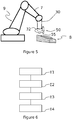
- the figure 5 is a schematic view of a robot 9 for additive manufacturing of an architectural structure 8 according to an embodiment of the invention.
- a robot 9 comprises an articulated arm 7, controlled by a control unit not shown in the figures, which carries the extrusion head 30 of an extrusion system according to the invention.
- the robot 9 is controlled by a control unit to cause the displacement of the extrusion head 30 along a predetermined trajectory making it possible to manufacture the architectural structure 8 by stacking layers of extruded beads.
- the implementation of the fluidization device 50 makes it possible, as indicated above, to maximize the adhesion between the beads.
- the figure 6 is a schematic view of a process for the extrusion of beads of cementitious material for an additive manufacturing robot for architectural structures according to the invention.
- the method comprises a first step E1 of supplying building material to an extrusion head of building material cords from a building material storage tank, said extrusion head comprising a mouth of building material inlet and an outlet nozzle configured to form extruded building material beads.
- the method comprises a step E2 of moving said extrusion head along a predetermined path to form an architectural structure by stacking layers of extruded beads.
- the method also comprises a concomitant step E3 of extruding strands of construction material by the extrusion head during the movement of the extrusion head on said predetermined path.
- the method comprises a concomitant step E4 of fluidification, in downstream of said extrusion head on said predetermined path, from the lower bead 6 to the bead 7 during extrusion, which makes it possible to maximize the adhesion between the cords 6 and 7.
- a method according to the invention is preferably implemented by a robot according to the invention.
- the robot can be a six-axis robot, mounted on rails or not, on a gantry or not.
- the robot can also be a cable robot or any type of robot whose positioning system, such as an articulated arm, can be controlled by computer.
- a robot according to the invention can be used to manufacture all types of architectural pieces.
- Such an architectural piece can be a reinforcement piece, a building, and in general, any piece of cementitious material.
- the architectural pieces produced by the use of an extrusion system according to the invention can be of various scales. It can be a portion of a pole, an entire pole, a wall, a slab element, a building, street furniture, a sculpture, etc.
Landscapes
- Engineering & Computer Science (AREA)
- Mechanical Engineering (AREA)
- Manufacturing & Machinery (AREA)
- Chemical & Material Sciences (AREA)
- Architecture (AREA)
- Ceramic Engineering (AREA)
- Materials Engineering (AREA)
- Civil Engineering (AREA)
- Structural Engineering (AREA)
- Coating Apparatus (AREA)
- Devices For Post-Treatments, Processing, Supply, Discharge, And Other Processes (AREA)
- Press-Shaping Or Shaping Using Conveyers (AREA)
- Tyre Moulding (AREA)
Applications Claiming Priority (1)
| Application Number | Priority Date | Filing Date | Title |
|---|---|---|---|
| FR1860563A FR3088569B1 (fr) | 2018-11-15 | 2018-11-15 | Systeme d'extrusion de cordons de materiau de construction pour robot de fabrication additive de structures architecturales comprenant un dispositif de fluidification du materiau cimentaire extrude |
Publications (2)
| Publication Number | Publication Date |
|---|---|
| EP3674045A1 true EP3674045A1 (de) | 2020-07-01 |
| EP3674045B1 EP3674045B1 (de) | 2021-08-18 |
Family
ID=65685768
Family Applications (1)
| Application Number | Title | Priority Date | Filing Date |
|---|---|---|---|
| EP19207626.3A Active EP3674045B1 (de) | 2018-11-15 | 2019-11-07 | System zur extrusion von baumaterialsträngen für roboter zur additiven fertigung von architektonischen strukturen, das eine verflüssigungsvorrichtung des extrudierten zementmaterials umfasst |
Country Status (3)
| Country | Link |
|---|---|
| EP (1) | EP3674045B1 (de) |
| ES (1) | ES2894236T3 (de) |
| FR (1) | FR3088569B1 (de) |
Families Citing this family (2)
| Publication number | Priority date | Publication date | Assignee | Title |
|---|---|---|---|---|
| FR3112356A1 (fr) * | 2020-07-08 | 2022-01-14 | Saint-Gobain Weber France | Fabrication additive d’élément de construction isolants |
| CN112518974B (zh) * | 2020-11-04 | 2022-02-08 | 广东博智林机器人有限公司 | 挤压成型装置及挤压成型方法 |
Citations (3)
| Publication number | Priority date | Publication date | Assignee | Title |
|---|---|---|---|---|
| WO2007050972A2 (en) * | 2005-10-26 | 2007-05-03 | University Of Southern California | Extruded wall with rib-like interior |
| WO2013064826A1 (en) * | 2011-11-01 | 2013-05-10 | Loughborough University | Method and apparatus for delivery of cementitious material |
| CN204354263U (zh) * | 2014-12-29 | 2015-05-27 | 中国建筑股份有限公司 | 一种适用于不同粘度的宾汉姆多组分流体混合挤出装置 |
-
2018
- 2018-11-15 FR FR1860563A patent/FR3088569B1/fr not_active Expired - Fee Related
-
2019
- 2019-11-07 ES ES19207626T patent/ES2894236T3/es active Active
- 2019-11-07 EP EP19207626.3A patent/EP3674045B1/de active Active
Patent Citations (3)
| Publication number | Priority date | Publication date | Assignee | Title |
|---|---|---|---|---|
| WO2007050972A2 (en) * | 2005-10-26 | 2007-05-03 | University Of Southern California | Extruded wall with rib-like interior |
| WO2013064826A1 (en) * | 2011-11-01 | 2013-05-10 | Loughborough University | Method and apparatus for delivery of cementitious material |
| CN204354263U (zh) * | 2014-12-29 | 2015-05-27 | 中国建筑股份有限公司 | 一种适用于不同粘度的宾汉姆多组分流体混合挤出装置 |
Also Published As
| Publication number | Publication date |
|---|---|
| FR3088569B1 (fr) | 2020-10-16 |
| FR3088569A1 (fr) | 2020-05-22 |
| ES2894236T3 (es) | 2022-02-14 |
| EP3674045B1 (de) | 2021-08-18 |
Similar Documents
| Publication | Publication Date | Title |
|---|---|---|
| EP3638473B1 (de) | System zum extrudieren von baumaterial für einen roboter zur generativen fertigung von architekturstrukturen mit einer vorrichtung zum einbringen von verstärkungsfasern | |
| EP3638475B1 (de) | System zum extrudieren zementartiger materialschichten für einen roboter zur generativen fertigung von architekturstrukturen | |
| EP3674045B1 (de) | System zur extrusion von baumaterialsträngen für roboter zur additiven fertigung von architektonischen strukturen, das eine verflüssigungsvorrichtung des extrudierten zementmaterials umfasst | |
| FR3070896B1 (fr) | Systeme d'extrusion de cordons de materiau cimentaire pour robots de fabrication additive de structures architecturales colorees | |
| EP3041600B1 (de) | Vorrichtung zum sprühen eines gemisches und verfahren zur herstellung eines gemisches | |
| FR3032957A3 (de) | ||
| EP3638476B1 (de) | System zum extrudieren zementartiger materialperlen für einen roboter zur generativen fertigung von architekturstrukturen | |
| EP0732987A1 (de) | Verfahren und vorrichtung zur herstellung von werkstücken durch phototransformation von stoff | |
| EP2782711B1 (de) | Vorrichtung mit einem luftkasten zur abgabe von strahlen aus einer kryogenen flüssigkeit | |
| EP3231786B1 (de) | Statischer mischer mit einer schervorrichtung, und herstellungsverfahren eines sprengstoffs | |
| WO2023036864A1 (fr) | Système d'extrusion de materiau de construction enrichi de granulats et/ou de fibres aciers pour fabrication additive de structures architecturales | |
| EP3616865B1 (de) | Vorrichtung und verfahren zum dreidimensionalen drucken in gel | |
| WO2012080681A1 (fr) | Installation pour la mise en relief d'une couche fraiche d'enduit hydraulique de finition | |
| FR3068911A1 (fr) | Tete d'extrusion de cordons de materiaux de construction d'un robot de fabrication additive equipee d'un dispositif de lissage | |
| FR3007780A1 (fr) | Machine pour le pompage de mortiers, enduits, betons ou analogue | |
| CA2153190A1 (fr) | Methode et dispositif de pompage a jets sequentiels | |
| FR3079230A1 (fr) | Procede de fabrication additive de ceramique par voie liquide et dispositif pour la mise en œuvre dudit procede | |
| WO1999010092A1 (fr) | Melangeur liquide(s)/solide(s) rotatif, en continu, a oeil ouvert | |
| WO2024078919A1 (fr) | Système d'extrusion de materiau de construction equipé d'un dispositif de mesure de la largeur des cordons extrudés | |
| FR2609756A1 (fr) | Dispositif d'aspiration | |
| FR3126333A1 (fr) | contrôle d’impression 3D | |
| EP4257824A1 (de) | Verfahren zur steuerung einer pumpe einer arbeitsmaschine | |
| FR2767719A1 (fr) | Turbine pour melangeur liquide(s) / solide(s) rotatif, en continu, a oeil ouvert | |
| FR2570443A1 (fr) | Pompe pour la distribution de matieres a viscosite elevee et son application dans une installation de fourniture d'un cordon de matiere plastique destine a servir d'intercalaire dans des vitrages multiples |
Legal Events
| Date | Code | Title | Description |
|---|---|---|---|
| PUAI | Public reference made under article 153(3) epc to a published international application that has entered the european phase |
Free format text: ORIGINAL CODE: 0009012 |
|
| STAA | Information on the status of an ep patent application or granted ep patent |
Free format text: STATUS: THE APPLICATION HAS BEEN PUBLISHED |
|
| AK | Designated contracting states |
Kind code of ref document: A1 Designated state(s): AL AT BE BG CH CY CZ DE DK EE ES FI FR GB GR HR HU IE IS IT LI LT LU LV MC MK MT NL NO PL PT RO RS SE SI SK SM TR |
|
| AX | Request for extension of the european patent |
Extension state: BA ME |
|
| STAA | Information on the status of an ep patent application or granted ep patent |
Free format text: STATUS: REQUEST FOR EXAMINATION WAS MADE |
|
| 17P | Request for examination filed |
Effective date: 20210111 |
|
| RBV | Designated contracting states (corrected) |
Designated state(s): AL AT BE BG CH CY CZ DE DK EE ES FI FR GB GR HR HU IE IS IT LI LT LU LV MC MK MT NL NO PL PT RO RS SE SI SK SM TR |
|
| GRAP | Despatch of communication of intention to grant a patent |
Free format text: ORIGINAL CODE: EPIDOSNIGR1 |
|
| STAA | Information on the status of an ep patent application or granted ep patent |
Free format text: STATUS: GRANT OF PATENT IS INTENDED |
|
| GRAS | Grant fee paid |
Free format text: ORIGINAL CODE: EPIDOSNIGR3 |
|
| GRAA | (expected) grant |
Free format text: ORIGINAL CODE: 0009210 |
|
| STAA | Information on the status of an ep patent application or granted ep patent |
Free format text: STATUS: THE PATENT HAS BEEN GRANTED |
|
| INTG | Intention to grant announced |
Effective date: 20210630 |
|
| AK | Designated contracting states |
Kind code of ref document: B1 Designated state(s): AL AT BE BG CH CY CZ DE DK EE ES FI FR GB GR HR HU IE IS IT LI LT LU LV MC MK MT NL NO PL PT RO RS SE SI SK SM TR |
|
| REG | Reference to a national code |
Ref country code: GB Ref legal event code: FG4D Free format text: NOT ENGLISH |
|
| REG | Reference to a national code |
Ref country code: CH Ref legal event code: EP |
|
| REG | Reference to a national code |
Ref country code: DE Ref legal event code: R096 Ref document number: 602019006968 Country of ref document: DE |
|
| REG | Reference to a national code |
Ref country code: IE Ref legal event code: FG4D Free format text: LANGUAGE OF EP DOCUMENT: FRENCH Ref country code: AT Ref legal event code: REF Ref document number: 1421223 Country of ref document: AT Kind code of ref document: T Effective date: 20210915 |
|
| REG | Reference to a national code |
Ref country code: NL Ref legal event code: FP |
|
| REG | Reference to a national code |
Ref country code: LT Ref legal event code: MG9D |
|
| PG25 | Lapsed in a contracting state [announced via postgrant information from national office to epo] |
Ref country code: SE Free format text: LAPSE BECAUSE OF FAILURE TO SUBMIT A TRANSLATION OF THE DESCRIPTION OR TO PAY THE FEE WITHIN THE PRESCRIBED TIME-LIMIT Effective date: 20210818 Ref country code: RS Free format text: LAPSE BECAUSE OF FAILURE TO SUBMIT A TRANSLATION OF THE DESCRIPTION OR TO PAY THE FEE WITHIN THE PRESCRIBED TIME-LIMIT Effective date: 20210818 Ref country code: HR Free format text: LAPSE BECAUSE OF FAILURE TO SUBMIT A TRANSLATION OF THE DESCRIPTION OR TO PAY THE FEE WITHIN THE PRESCRIBED TIME-LIMIT Effective date: 20210818 Ref country code: FI Free format text: LAPSE BECAUSE OF FAILURE TO SUBMIT A TRANSLATION OF THE DESCRIPTION OR TO PAY THE FEE WITHIN THE PRESCRIBED TIME-LIMIT Effective date: 20210818 Ref country code: NO Free format text: LAPSE BECAUSE OF FAILURE TO SUBMIT A TRANSLATION OF THE DESCRIPTION OR TO PAY THE FEE WITHIN THE PRESCRIBED TIME-LIMIT Effective date: 20211118 Ref country code: PT Free format text: LAPSE BECAUSE OF FAILURE TO SUBMIT A TRANSLATION OF THE DESCRIPTION OR TO PAY THE FEE WITHIN THE PRESCRIBED TIME-LIMIT Effective date: 20211220 Ref country code: BG Free format text: LAPSE BECAUSE OF FAILURE TO SUBMIT A TRANSLATION OF THE DESCRIPTION OR TO PAY THE FEE WITHIN THE PRESCRIBED TIME-LIMIT Effective date: 20211118 Ref country code: LT Free format text: LAPSE BECAUSE OF FAILURE TO SUBMIT A TRANSLATION OF THE DESCRIPTION OR TO PAY THE FEE WITHIN THE PRESCRIBED TIME-LIMIT Effective date: 20210818 |
|
| REG | Reference to a national code |
Ref country code: ES Ref legal event code: FG2A Ref document number: 2894236 Country of ref document: ES Kind code of ref document: T3 Effective date: 20220214 |
|
| PG25 | Lapsed in a contracting state [announced via postgrant information from national office to epo] |
Ref country code: PL Free format text: LAPSE BECAUSE OF FAILURE TO SUBMIT A TRANSLATION OF THE DESCRIPTION OR TO PAY THE FEE WITHIN THE PRESCRIBED TIME-LIMIT Effective date: 20210818 Ref country code: LV Free format text: LAPSE BECAUSE OF FAILURE TO SUBMIT A TRANSLATION OF THE DESCRIPTION OR TO PAY THE FEE WITHIN THE PRESCRIBED TIME-LIMIT Effective date: 20210818 Ref country code: GR Free format text: LAPSE BECAUSE OF FAILURE TO SUBMIT A TRANSLATION OF THE DESCRIPTION OR TO PAY THE FEE WITHIN THE PRESCRIBED TIME-LIMIT Effective date: 20211119 |
|
| PG25 | Lapsed in a contracting state [announced via postgrant information from national office to epo] |
Ref country code: DK Free format text: LAPSE BECAUSE OF FAILURE TO SUBMIT A TRANSLATION OF THE DESCRIPTION OR TO PAY THE FEE WITHIN THE PRESCRIBED TIME-LIMIT Effective date: 20210818 |
|
| REG | Reference to a national code |
Ref country code: DE Ref legal event code: R097 Ref document number: 602019006968 Country of ref document: DE |
|
| PG25 | Lapsed in a contracting state [announced via postgrant information from national office to epo] |
Ref country code: SM Free format text: LAPSE BECAUSE OF FAILURE TO SUBMIT A TRANSLATION OF THE DESCRIPTION OR TO PAY THE FEE WITHIN THE PRESCRIBED TIME-LIMIT Effective date: 20210818 Ref country code: SK Free format text: LAPSE BECAUSE OF FAILURE TO SUBMIT A TRANSLATION OF THE DESCRIPTION OR TO PAY THE FEE WITHIN THE PRESCRIBED TIME-LIMIT Effective date: 20210818 Ref country code: RO Free format text: LAPSE BECAUSE OF FAILURE TO SUBMIT A TRANSLATION OF THE DESCRIPTION OR TO PAY THE FEE WITHIN THE PRESCRIBED TIME-LIMIT Effective date: 20210818 Ref country code: EE Free format text: LAPSE BECAUSE OF FAILURE TO SUBMIT A TRANSLATION OF THE DESCRIPTION OR TO PAY THE FEE WITHIN THE PRESCRIBED TIME-LIMIT Effective date: 20210818 Ref country code: CZ Free format text: LAPSE BECAUSE OF FAILURE TO SUBMIT A TRANSLATION OF THE DESCRIPTION OR TO PAY THE FEE WITHIN THE PRESCRIBED TIME-LIMIT Effective date: 20210818 Ref country code: AL Free format text: LAPSE BECAUSE OF FAILURE TO SUBMIT A TRANSLATION OF THE DESCRIPTION OR TO PAY THE FEE WITHIN THE PRESCRIBED TIME-LIMIT Effective date: 20210818 |
|
| PLBE | No opposition filed within time limit |
Free format text: ORIGINAL CODE: 0009261 |
|
| STAA | Information on the status of an ep patent application or granted ep patent |
Free format text: STATUS: NO OPPOSITION FILED WITHIN TIME LIMIT |
|
| PG25 | Lapsed in a contracting state [announced via postgrant information from national office to epo] |
Ref country code: MC Free format text: LAPSE BECAUSE OF FAILURE TO SUBMIT A TRANSLATION OF THE DESCRIPTION OR TO PAY THE FEE WITHIN THE PRESCRIBED TIME-LIMIT Effective date: 20210818 |
|
| 26N | No opposition filed |
Effective date: 20220519 |
|
| PG25 | Lapsed in a contracting state [announced via postgrant information from national office to epo] |
Ref country code: LU Free format text: LAPSE BECAUSE OF NON-PAYMENT OF DUE FEES Effective date: 20211107 |
|
| PG25 | Lapsed in a contracting state [announced via postgrant information from national office to epo] |
Ref country code: SI Free format text: LAPSE BECAUSE OF FAILURE TO SUBMIT A TRANSLATION OF THE DESCRIPTION OR TO PAY THE FEE WITHIN THE PRESCRIBED TIME-LIMIT Effective date: 20210818 |
|
| PG25 | Lapsed in a contracting state [announced via postgrant information from national office to epo] |
Ref country code: IE Free format text: LAPSE BECAUSE OF NON-PAYMENT OF DUE FEES Effective date: 20211107 |
|
| REG | Reference to a national code |
Ref country code: AT Ref legal event code: UEP Ref document number: 1421223 Country of ref document: AT Kind code of ref document: T Effective date: 20210818 |
|
| PG25 | Lapsed in a contracting state [announced via postgrant information from national office to epo] |
Ref country code: CY Free format text: LAPSE BECAUSE OF FAILURE TO SUBMIT A TRANSLATION OF THE DESCRIPTION OR TO PAY THE FEE WITHIN THE PRESCRIBED TIME-LIMIT Effective date: 20210818 |
|
| P01 | Opt-out of the competence of the unified patent court (upc) registered |
Effective date: 20230527 |
|
| PG25 | Lapsed in a contracting state [announced via postgrant information from national office to epo] |
Ref country code: HU Free format text: LAPSE BECAUSE OF FAILURE TO SUBMIT A TRANSLATION OF THE DESCRIPTION OR TO PAY THE FEE WITHIN THE PRESCRIBED TIME-LIMIT; INVALID AB INITIO Effective date: 20191107 |
|
| PGFP | Annual fee paid to national office [announced via postgrant information from national office to epo] |
Ref country code: NL Payment date: 20231006 Year of fee payment: 5 |
|
| PGFP | Annual fee paid to national office [announced via postgrant information from national office to epo] |
Ref country code: GB Payment date: 20231006 Year of fee payment: 5 |
|
| PGFP | Annual fee paid to national office [announced via postgrant information from national office to epo] |
Ref country code: IT Payment date: 20231124 Year of fee payment: 5 Ref country code: FR Payment date: 20231006 Year of fee payment: 5 Ref country code: DE Payment date: 20231006 Year of fee payment: 5 Ref country code: CH Payment date: 20231202 Year of fee payment: 5 |
|
| PGFP | Annual fee paid to national office [announced via postgrant information from national office to epo] |
Ref country code: BE Payment date: 20231006 Year of fee payment: 5 |
|
| PGFP | Annual fee paid to national office [announced via postgrant information from national office to epo] |
Ref country code: ES Payment date: 20240130 Year of fee payment: 5 |
|
| PG25 | Lapsed in a contracting state [announced via postgrant information from national office to epo] |
Ref country code: MK Free format text: LAPSE BECAUSE OF FAILURE TO SUBMIT A TRANSLATION OF THE DESCRIPTION OR TO PAY THE FEE WITHIN THE PRESCRIBED TIME-LIMIT Effective date: 20210818 |