EP3674045A1 - System for extrusion of beads of construction material for a robot for additive manufacturing of architectural structures including a device for fluidification of the extruded cement material - Google Patents
System for extrusion of beads of construction material for a robot for additive manufacturing of architectural structures including a device for fluidification of the extruded cement material Download PDFInfo
- Publication number
- EP3674045A1 EP3674045A1 EP19207626.3A EP19207626A EP3674045A1 EP 3674045 A1 EP3674045 A1 EP 3674045A1 EP 19207626 A EP19207626 A EP 19207626A EP 3674045 A1 EP3674045 A1 EP 3674045A1
- Authority
- EP
- European Patent Office
- Prior art keywords
- extrusion
- cords
- extrusion head
- bead
- extruded
- Prior art date
- Legal status (The legal status is an assumption and is not a legal conclusion. Google has not performed a legal analysis and makes no representation as to the accuracy of the status listed.)
- Granted
Links
- 238000001125 extrusion Methods 0.000 title claims abstract description 151
- 239000011324 bead Substances 0.000 title claims abstract description 102
- 239000000654 additive Substances 0.000 title claims abstract description 29
- 238000004519 manufacturing process Methods 0.000 title claims abstract description 29
- 230000000996 additive effect Effects 0.000 title claims abstract description 25
- 239000000463 material Substances 0.000 title claims description 37
- 239000004035 construction material Substances 0.000 title claims description 32
- 239000004568 cement Substances 0.000 title description 3
- 239000004566 building material Substances 0.000 claims abstract description 34
- 238000005243 fluidization Methods 0.000 claims abstract description 17
- 238000003860 storage Methods 0.000 claims description 19
- 238000000034 method Methods 0.000 claims description 15
- 239000012530 fluid Substances 0.000 claims description 9
- 239000002671 adjuvant Substances 0.000 claims description 7
- 238000006073 displacement reaction Methods 0.000 claims description 5
- 230000007246 mechanism Effects 0.000 claims description 5
- 238000002604 ultrasonography Methods 0.000 claims description 3
- 238000010276 construction Methods 0.000 description 18
- 238000007639 printing Methods 0.000 description 7
- 239000003795 chemical substances by application Substances 0.000 description 6
- 238000011144 upstream manufacturing Methods 0.000 description 5
- 238000010146 3D printing Methods 0.000 description 4
- 235000021183 entrée Nutrition 0.000 description 3
- 230000008569 process Effects 0.000 description 3
- 230000000593 degrading effect Effects 0.000 description 2
- 230000000704 physical effect Effects 0.000 description 2
- 238000005086 pumping Methods 0.000 description 2
- 238000000518 rheometry Methods 0.000 description 2
- 238000013019 agitation Methods 0.000 description 1
- 230000008859 change Effects 0.000 description 1
- 230000008021 deposition Effects 0.000 description 1
- 238000005516 engineering process Methods 0.000 description 1
- 239000010419 fine particle Substances 0.000 description 1
- 238000003304 gavage Methods 0.000 description 1
- 239000008240 homogeneous mixture Substances 0.000 description 1
- 239000000203 mixture Substances 0.000 description 1
- 230000002572 peristaltic effect Effects 0.000 description 1
- 239000011505 plaster Substances 0.000 description 1
- 230000010349 pulsation Effects 0.000 description 1
- 230000009467 reduction Effects 0.000 description 1
- 230000002787 reinforcement Effects 0.000 description 1
- 238000010008 shearing Methods 0.000 description 1
- 239000004094 surface-active agent Substances 0.000 description 1
- 230000001360 synchronised effect Effects 0.000 description 1
Images


Classifications
-
- B—PERFORMING OPERATIONS; TRANSPORTING
- B28—WORKING CEMENT, CLAY, OR STONE
- B28B—SHAPING CLAY OR OTHER CERAMIC COMPOSITIONS; SHAPING SLAG; SHAPING MIXTURES CONTAINING CEMENTITIOUS MATERIAL, e.g. PLASTER
- B28B1/00—Producing shaped prefabricated articles from the material
- B28B1/001—Rapid manufacturing of 3D objects by additive depositing, agglomerating or laminating of material
-
- B—PERFORMING OPERATIONS; TRANSPORTING
- B28—WORKING CEMENT, CLAY, OR STONE
- B28B—SHAPING CLAY OR OTHER CERAMIC COMPOSITIONS; SHAPING SLAG; SHAPING MIXTURES CONTAINING CEMENTITIOUS MATERIAL, e.g. PLASTER
- B28B1/00—Producing shaped prefabricated articles from the material
- B28B1/08—Producing shaped prefabricated articles from the material by vibrating or jolting
- B28B1/093—Producing shaped prefabricated articles from the material by vibrating or jolting by means directly acting on the material, e.g. by cores wholly or partly immersed in the material or elements acting on the upper surface of the material
- B28B1/0935—Producing shaped prefabricated articles from the material by vibrating or jolting by means directly acting on the material, e.g. by cores wholly or partly immersed in the material or elements acting on the upper surface of the material using only elements wholly or partly immersed in the material, e.g. cores
-
- B—PERFORMING OPERATIONS; TRANSPORTING
- B28—WORKING CEMENT, CLAY, OR STONE
- B28B—SHAPING CLAY OR OTHER CERAMIC COMPOSITIONS; SHAPING SLAG; SHAPING MIXTURES CONTAINING CEMENTITIOUS MATERIAL, e.g. PLASTER
- B28B3/00—Producing shaped articles from the material by using presses; Presses specially adapted therefor
- B28B3/20—Producing shaped articles from the material by using presses; Presses specially adapted therefor wherein the material is extruded
-
- B—PERFORMING OPERATIONS; TRANSPORTING
- B33—ADDITIVE MANUFACTURING TECHNOLOGY
- B33Y—ADDITIVE MANUFACTURING, i.e. MANUFACTURING OF THREE-DIMENSIONAL [3-D] OBJECTS BY ADDITIVE DEPOSITION, ADDITIVE AGGLOMERATION OR ADDITIVE LAYERING, e.g. BY 3-D PRINTING, STEREOLITHOGRAPHY OR SELECTIVE LASER SINTERING
- B33Y10/00—Processes of additive manufacturing
-
- B—PERFORMING OPERATIONS; TRANSPORTING
- B33—ADDITIVE MANUFACTURING TECHNOLOGY
- B33Y—ADDITIVE MANUFACTURING, i.e. MANUFACTURING OF THREE-DIMENSIONAL [3-D] OBJECTS BY ADDITIVE DEPOSITION, ADDITIVE AGGLOMERATION OR ADDITIVE LAYERING, e.g. BY 3-D PRINTING, STEREOLITHOGRAPHY OR SELECTIVE LASER SINTERING
- B33Y30/00—Apparatus for additive manufacturing; Details thereof or accessories therefor
-
- E—FIXED CONSTRUCTIONS
- E04—BUILDING
- E04G—SCAFFOLDING; FORMS; SHUTTERING; BUILDING IMPLEMENTS OR AIDS, OR THEIR USE; HANDLING BUILDING MATERIALS ON THE SITE; REPAIRING, BREAKING-UP OR OTHER WORK ON EXISTING BUILDINGS
- E04G21/00—Preparing, conveying, or working-up building materials or building elements in situ; Other devices or measures for constructional work
- E04G21/02—Conveying or working-up concrete or similar masses able to be heaped or cast
- E04G21/04—Devices for both conveying and distributing
- E04G21/0418—Devices for both conveying and distributing with distribution hose
- E04G21/0427—Devices for both conveying and distributing with distribution hose on a static support, e.g. crane
-
- E—FIXED CONSTRUCTIONS
- E04—BUILDING
- E04G—SCAFFOLDING; FORMS; SHUTTERING; BUILDING IMPLEMENTS OR AIDS, OR THEIR USE; HANDLING BUILDING MATERIALS ON THE SITE; REPAIRING, BREAKING-UP OR OTHER WORK ON EXISTING BUILDINGS
- E04G21/00—Preparing, conveying, or working-up building materials or building elements in situ; Other devices or measures for constructional work
- E04G21/02—Conveying or working-up concrete or similar masses able to be heaped or cast
- E04G21/04—Devices for both conveying and distributing
- E04G21/0418—Devices for both conveying and distributing with distribution hose
- E04G21/0445—Devices for both conveying and distributing with distribution hose with booms
- E04G21/0463—Devices for both conveying and distributing with distribution hose with booms with boom control mechanisms, e.g. to automate concrete distribution
Definitions
- the invention relates to additive manufacturing of building materials.
- the invention relates more particularly to a system for extruding cords of building material for an additive manufacturing robot for architectural structures by stacking successive layers of extruded cords comprising a device for fluidizing the extruded cords.
- the invention also relates to a robot for additive manufacturing of architectural structures comprising such an extrusion system.
- the invention also relates to a method of extruding beads of construction material.
- building materials designate all types of materials that can be used to produce architectural structures by stacking layers of beads extruded from these materials. These are, for example, cementitious materials, plaster-based materials, and generally all viscous paste materials compatible with the additive manufacturing of architectural structures.
- architectural structures designate both individual building elements (bridge, pillar, wall, street furniture, etc.), complete structures (building, house, building, etc.) and parts. various architectural works (artistic works, sculptures, etc.).
- Additive manufacturing of architectural structures by stacking layers of extruded cords, from which 3D printing of construction materials, in particular cement materials, is derived is a new technology very promising in the field of architecture and construction.
- 3D printing of building material brings many advantages compared to traditional techniques among which in particular the possibility of being able to realize complex shapes by adding successive layers of building material, the speed of construction operations, the reduction costs and labor, improved safety on construction sites, etc.
- the mastery of 3D printing of construction material calls on skills in the field of fluid mechanics, mechanics, electronics and civil engineering.
- the extrusion of construction material intended for the manufacture of an architectural structure implements an extrusion head (also sometimes referred to by the terms of print head) comprising a construction material inlet mouth, a nozzle of construction material outlet and a metering pump configured to be able to convey the construction material from the inlet mouth to the outlet nozzle.
- the extrusion of building material also implements a circuit for supplying the extrusion head with building material comprising a building material storage tank, a pipe connecting the storage tank and the inlet of the head. extrusion and a pump for feeding the building material supply pipe from the storage tank.
- the extrusion head is intended to be moved by a positioning system, such as an articulated arm of a robot, along a predetermined path, so as to be able to form an architectural piece by stacking successive layers of cords extruded.
- a positioning system such as an articulated arm of a robot
- cementitious material must be supplied in a rheological state compatible with pumping of this material, that is to say sufficiently fluid to be able to be pumped from the reservoir of storage and conveyed to the outlet nozzle, when its state must be viscous enough (that is to say less fluid) downstream of the outlet nozzle to be able to form a self-supporting layer capable of supporting the next layer.
- Such a system therefore makes it possible to convey the cementitious material to the print head in a state compatible with optimized pumping and to not modify its physical properties (for example its rheology, its surfactant force, its plasticity, its stability, its thixotropy, etc.) only before deposition of the layer by the outlet nozzle.
- its physical properties for example its rheology, its surfactant force, its plasticity, its stability, its thixotropy, etc.
- This solution produces good results but does not yet make it possible to completely resolve the problem of the heterogeneity of the architectural structure imprinted by such a system.
- This heterogeneity of the printed structure results in particular from the difficulty of fusing the cords with each other because the freshly extruded bead (also designated throughout the text by the terms "upper bead”) does not have the same rheological state. than the previously extruded bead (also designated throughout the text by the terms "lower bead”), in particular when accelerating agents are used to accelerate the setting of the cords.
- This lack of heterogeneity can generate areas of weakness at each interface between the cords, in particular when the cords extend over long straight portions or when the print head of the additive manufacturing robot moves at low speed, such that the time between the extrusion of the upper layer and the lower layer is long enough for the properties of the material to change from one layer to another.
- the inventors therefore sought to improve their printing system to overcome these problems.
- the invention therefore aims to provide a system for extruding construction material, in particular cementitious material, which makes it possible to solve at least some of the drawbacks of the previous solutions.
- the invention aims in particular to provide, in at least one embodiment, a system for extruding construction material, in particular cementitious material, which makes it possible to fabricate architectural structures without the need to interrupt printing in order to wait taking the cords.
- the invention also aims to provide, in at least one embodiment, a system for extruding construction material, in particular cementitious material, compatible with the use of accelerating agents.
- the invention also aims to provide, in at least one embodiment of the invention, an extrusion system which makes it possible to fabricate architectural structures whose geometry is not imposed by height constraints.
- the invention also aims to provide, in at least one embodiment of the invention, an extrusion system which allows the fabrication of architectural structures in a precise, stable, repeatable manner and at low cost.
- the invention also aims to provide, in at least one embodiment of the invention, an extrusion system which makes it possible to strengthen the cohesion of two layers of superposed beads.
- the invention also aims to provide a robot equipped with a system for extruding cords of construction material according to the invention.
- the invention finally aims to provide a method of extruding strands of construction material.
- a system according to the invention is characterized in that it further comprises a device for fluidizing the extruded cords adapted to be able, for at least one bead, to a layer of cords being extruded by said extrusion head on said predetermined trajectory, said upper bead, to fluidize at least one bead of the layer of cords previously extruded, said lower bead, before extrusion of the upper bead on this lower bead, so as to maximize the adhesion between said upper bead being extrusion and said lower bead fluidized by said fluidization device.
- a system according to the invention therefore makes it possible to overcome the problems of the previous systems by thinning the beads of the lower layer before pouring the upper layer.
- the inventors had the idea, which goes against the various teachings of the technical field, to re-fluidize the cords after extrusion so that they find a state close to that of the cords during extrusion.
- This idea could appear surprising at first sight insofar as an extrusion system generally implements an accelerating agent intended precisely to accelerate the setting at the extrusion head outlet so that the layer thus extruded can support the following cords.
- an extruded bead can regain a fluid state if it is agitated quickly after its extrusion and that this makes it possible to improve the cohesion between the layers.
- the idea is therefore to locally thin the lower bead to maximize the adhesion between the layers, without however calling into question the use of accelerating agents which make it possible to accelerate the setting.
- This refluidification of the beads of the lower layer reduces the porosity of the beads and therefore generates an interface between the beads of better quality.
- this refluidification of the bead of the lower layer takes place just before the removal of the bead of the upper layer (insofar as the device is configured to thin the lower bead downstream of the extrusion head along the trajectory of displacement of the extrusion head), which allows the bead of the lower layer to regain its fluid state without degrading the material, just before receiving the upper bead.
- downstream of the extrusion head designate the space to which the extrusion head is directed when it follows the predetermined path.
- a portion of lower cord downstream of the print head is a portion of a cord of the layer lower than that being extruded which is arranged in front of the extrusion head and which is about to be covered by the bead during extrusion.
- said fluidification device comprises means for vibrating the lower cord adapted to be able to locally vibrate said lower cord, before extrusion of the upper cord on this lower cord, so as to be able to modify the shear threshold of said cord lower which makes it pass from a viscous state corresponding to the state of the bead after extrusion, to a less viscous fluid state maximizing the adhesion between said upper bead during extrusion and said lower bead.
- a system makes it possible to fluidize the bead of the lower layer by implementing vibrating means configured to be able to vibrate locally the bead of the lower layer.
- This vibration the bead is preferably made in a controlled manner just before the removal of the upper bead to allow the lower bead to regain a fluid state without degrading the material or the geometry of the removal.
- the system according to this variant comprises means for vibrating said lower cord adapted to be able to locally vibrate said lower cord downstream from said extrusion head along said predetermined path so that it can modify the threshold this shearing of the lower cord.
- Different vibrating means can be used to thin the lower cords.
- said vibration means comprise at least one needle, called a vibrating needle, connected to a vibration motor of said vibrating needle and to a mechanism adapted to be able to move said vibrating needle by a position, said retracted position in which it is spaced from said lower cord of said lower layer, at a position, said vibration position, in which one end of the needle can be inserted into said lower cord of said lower layer.
- a vibrating needle is used to allow local agitation of the lower bead so that it recovers a fluid state making it possible to maximize the adhesion between the upper bead during extrusion and the lower bead.
- This vibrating needle preferably has a diameter much less than the thickness of the lower cord, for example equal to less than 10% of the width of the thickness of the lower cord.
- the needle placement mechanism is preferably configured to be able to place the needle in said vibration position in the center of the bead.
- the vibration motor is preferably configured to be able to drive the vibrating needle according to rapid movements and of small amplitude relative to the thickness of the cord, making it possible to soften the cord.
- the vibrating needle is replaced by a vibrating blade connected to a mechanism adapted to move the blade from said position retracted in which it is spaced from said lower cord of said lower layer, at said vibration position in which one end of the blade is inserted into said lower cord of said lower layer.
- the vibrating needle or the vibrating blade can be configured so that, in the vibration position, it can be inserted into at least two successive lower cords so as to be able to fluidize, not only the bead of the previously extruded layer, but also the penultimate layer, that is to say that extruded before the extrusion of said lower layer.
- the vibration means comprise a directional generator of mechanical waves adapted to be able to generate mechanical waves towards said lower bead of said lower layer so as to be able to locally fluidize this lower bead.
- the fluidization of the lower bead is obtained by a directional generator of mechanical waves. This makes it possible to thin the bead without mechanical contact with the bead.
- the generator of mechanical waves is for example a generator of sound waves, of the infrasound type at high amplitude or ultrasound at low amplitude.
- a generator can for example comprise a piezoelectric actuator.
- the choice of the type of sound wave generator depends on the type of material and additives used by the printing system.
- said fluidification device is carried by said extrusion head via a mounting support.
- This advantageous variant makes it possible to link the movements of the extrusion head to the movements of the device for fluidizing the beads.
- this advantageous variant makes it possible to fluidize the cords in a synchronized manner with the extrusion of the cords.
- the extrusion head comprises a casing extending along a direction, called the longitudinal direction, and the mounting support carrying said fluidization device is mounted so as to be able to rotate on said casing of said head. extrusion around an axis extending along said longitudinal direction.
- the fluidization device can be positioned opposite any extruded bead, whatever its orientation.
- this variant makes it possible to fluidize the beads at the level of the curvatures and angles of the architectural structure.
- the mounting support is movable in translation along the casing of the extrusion head so as to be able to adapt the distance which separates the fluidization device and the bead to be fluidized.
- the invention also relates to a robot for additive manufacturing of architectural structures comprising a positioning system, such as an articulated arm, controlled by a control unit, and an extrusion system comprising an extrusion head mounted on said system. positioning so that the displacement of the positioning system carrying said extrusion head along a predetermined trajectory allows the production of an architectural structure by stacking layers of beads of cementitious material, characterized in that said extrusion system conforms to the invention.
- a method according to the invention is advantageously implemented by an extrusion system according to the invention and an extrusion system according to the invention advantageously implements a method according to the invention.
- the invention also relates to an extrusion system and an additive manufacturing robot characterized in combination by all or some of the characteristics mentioned above or below.
- An extrusion system comprises, as shown in the figure 1 , a storage tank 10 for a cementitious construction material, an extrusion head 30, a circuit 20 for supplying cementitious material for construction of the extrusion head 30, an adjuvant device 40 connected to the head printing 30, and a fluidization device 50 of the extruded beads.
- the storage tank 10 is preferably a hopper comprising an upper opening 11 adapted to receive mixes of cementitious materials and a lower outlet 12 connected to the supply circuit 20.
- the hopper may further comprise an agitator 13 comprising a shaft 14 carrying a plurality of side blades 15 by means of axes perpendicular to the shaft 14, and a motor 16 for rotating the shaft 14.
- the motor 16 is for example an electric motor configured to be able to drive at low speed, for example at a speed of six revolutions per minute, the shaft 14 of the agitator 13.
- the use of a heat engine is of course possible without modifying system performance extrusion according to the invention.
- the role of the agitator is to be able to maintain the cementitious material in the hopper in an almost constant rheological state before being led to the print head by the supply circuit.
- the cementitious material used is for example a premix based on cement with fine particles, hydrated and fluidized.
- the supply circuit 20 connects the storage tank 10 to the extrusion head 30.
- This circuit comprises a pipe 21 connecting the outlet 12 of the storage tank 10 to an inlet mouth 31 of the extrusion head 30.
- This pipe 21 is for example a flexible pipe.
- the supply circuit 20 further comprises a booster pump 22.
- This booster pump 22 is for example controlled by pressure / flow rate by a pressure sensor 33 arranged in the vicinity of the inlet mouth 31 of the extrusion head 30.
- This booster pump 22 is for example an eccentric screw pump so as to be able to convey the cementitious material to the extrusion head 30 while minimizing the pulsations.
- This booster pump 22 is for example a pump sold under the references Putzmeister® FP-V Mono. Of course, other pumps can be used without modifying the performance of the invention.
- the pressure / flow sensor 33 can be of any known type. It is for example a sensor sold under the reference ifm® PF2953. Of course, other sensors can be used without modifying the performance of the invention.
- the booster pump 22 is configured to follow a predetermined control law which can be configured by an operator as required. For example, the control law is configured to maintain the pressure of the cementitious material between 2 and 6 bars.
- the extrusion head 30 comprises, as shown diagrammatically by the figure 2 , an inlet mouth 31 connected to the supply circuit 20 and an outlet nozzle 34 configured to form beads of cementitious material.
- the extrusion head preferably further comprises a mixing enclosure 35 arranged upstream of the outlet nozzle 34.
- This mixing chamber 35 is equipped with a dynamic mixer adapted to be able to mix the cementitious material and any additives supplied by the additive device 40.
- This dynamic mixer comprises for example a shaft 37 extending longitudinally in the mixing enclosure 35 on which are mounted radial fingers 38 distributed along the shaft 37.
- the dynamic mixer also comprises a motor 39 configured to be able to drive the 'shaft 37 in rotation so as to be able to provide a homogeneous mixture of the cementitious material.
- This motor 39 can be an electric motor, a heat engine, and in general all types of motors. According to the embodiment of the figures, the motor 39 is offset relative to the shaft 37 in order to minimize the disturbance of the mixture in the mixing enclosure 35.
- the extrusion head 30 also comprises a metering pump 51 with an eccentric screw configured to be able to convey the cementitious material from the inlet mouth 31 to the outlet nozzle, passing through the mixing enclosure 35.
- a pump dosing is for example a pump sold under the references Viscotec® 3VMP36.
- Viscotec® 3VMP36 Viscotec® 3VMP36
- the metering pump 51 is replaced by a volumetric metering device configured to be able to ensure a constant flow rate over a predetermined operating range.
- the extrusion head 30 also includes a safety pressure sensor 52 arranged upstream of the mixing enclosure 35.
- This sensor is for example a sensor sold under the references ifm® PF2953. Of course, other sensors can be used without modifying the performance of the invention.
- This safety sensor 52 makes it possible to measure the pressure upstream of the mixing enclosure 35 so as to be able to prevent risks of clogging of the mixing enclosure 35 or of the outlet nozzle 34.
- This sensor can for example be connected an automatic shutdown system of the extrusion system as soon as a pressure threshold is reached.
- the outlet nozzle 34 of the print head is preferably removable so as to be able to adapt the shape of the outlet nozzle 34 to the part to be manufactured.
- the section of the outlet nozzle 34 can be adapted to each type of part produced, or even changed during printing to modify the section of the cords of certain portions of the part produced.
- the outlet nozzle comprises for example a threaded outer wall which cooperates with a threaded inner portion of the wall of the print head delimiting the mixing enclosure 35.
- the outlet nozzle comprises a internal threaded wall which cooperates with an external threaded portion of the wall of the print head.
- the adjuvant device 40 comprises as shown in the figure 1 a barrel 41 containing a plurality of adjuvants, at least one needle 42 connected to the barrel 41 by means of a pipe 48, a volumetric metering device and a peristaltic pump 43.
- the adjuvants of the barrel 41 of adjuvants can be of all types. These are additives aimed at modifying any physical property of the cementitious material (mainly its rheology, but also its surface-active force, its plasticity, its stability, its thixotropy, etc.).
- the adjuvants are, for example, accelerating agents making it possible to accelerate the setting of the cords.
- the needle 42 opens into the mixing enclosure 35, opposite the outlet nozzle 34, in a direction of addition, which forms for example an angle of 45 ° with the main direction of the enclosure mixed.
- the fluidization device 50 of the beads is schematically represented on the Figures 1 and 2 by the reference 50 and is illustrated in more detail on the figures 3 and 4 for two separate embodiments.
- the fluidization device 50 is carried by the extrusion head 30 by means of a mounting support 32.
- This mounting support 32 can be mounted movable in rotation about the main axis of the extrusion head so as to be able to move the fluidization device around the extrusion head.
- the extrusion head is moved along a predetermined path represented schematically by the arrow referenced F1 on the figures 3 and 4 , i.e. from left to right.
- the elements to the left of the head are said upstream of the head along the predetermined path and the elements to the right of the head are said to be downstream of the head along the predetermined path.
- the extrusion head is moved along the predetermined path to form an architectural structure 8 by successive stacking of layers of extruded beads.
- the bead being extruded called the upper bead
- the extruded bead of the lower layer called the lower bead
- the fluidization device is configured to be able to fluidize the bead 6 downstream of the extrusion head 30 along the predetermined path F1, so as to maximize the adhesion between the upper bead 7 during extrusion and the lower bead 6.
- the fluidization device 50 comprises means for vibrating the lower cord 6 which are in the form of a needle 55 connected to a motor, not shown in the figures, making it possible to vibrate the needle.
- This motor is for example housed in a casing 53.
- the motor is for example configured to be able to act on the needle 55 so that it is driven in a series of fast back and forth movements of small amplitude in the cord 6 , relative to the thickness of the bead.
- the vibrating needle 55 can be connected to a mechanism adapted to be able to move it from a retracted position in which it is spaced from the lower cord 6, to a vibrating position, in which one end of the needle 55 can be inserted into the lower cord 6.
- the vibration means comprise a directional generator of mechanical waves 54, such as sound waves, of the infrasound or ultrasound type, adapted to be able to generate waves 54 towards the lower cord 6.
- This generator comprises for example a piezoelectric actuator.
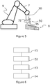
- the figure 5 is a schematic view of a robot 9 for additive manufacturing of an architectural structure 8 according to an embodiment of the invention.
- a robot 9 comprises an articulated arm 7, controlled by a control unit not shown in the figures, which carries the extrusion head 30 of an extrusion system according to the invention.
- the robot 9 is controlled by a control unit to cause the displacement of the extrusion head 30 along a predetermined trajectory making it possible to manufacture the architectural structure 8 by stacking layers of extruded beads.
- the implementation of the fluidization device 50 makes it possible, as indicated above, to maximize the adhesion between the beads.
- the figure 6 is a schematic view of a process for the extrusion of beads of cementitious material for an additive manufacturing robot for architectural structures according to the invention.
- the method comprises a first step E1 of supplying building material to an extrusion head of building material cords from a building material storage tank, said extrusion head comprising a mouth of building material inlet and an outlet nozzle configured to form extruded building material beads.
- the method comprises a step E2 of moving said extrusion head along a predetermined path to form an architectural structure by stacking layers of extruded beads.
- the method also comprises a concomitant step E3 of extruding strands of construction material by the extrusion head during the movement of the extrusion head on said predetermined path.
- the method comprises a concomitant step E4 of fluidification, in downstream of said extrusion head on said predetermined path, from the lower bead 6 to the bead 7 during extrusion, which makes it possible to maximize the adhesion between the cords 6 and 7.
- a method according to the invention is preferably implemented by a robot according to the invention.
- the robot can be a six-axis robot, mounted on rails or not, on a gantry or not.
- the robot can also be a cable robot or any type of robot whose positioning system, such as an articulated arm, can be controlled by computer.
- a robot according to the invention can be used to manufacture all types of architectural pieces.
- Such an architectural piece can be a reinforcement piece, a building, and in general, any piece of cementitious material.
- the architectural pieces produced by the use of an extrusion system according to the invention can be of various scales. It can be a portion of a pole, an entire pole, a wall, a slab element, a building, street furniture, a sculpture, etc.
Abstract
L'invention concerne un système d'extrusion de cordons de matériau de construction pour robot (9) de fabrication additive de structures architecturales (8) comprenant : une tête d'extrusion (30) de cordons de matériau de construction déplacée le long d'une trajectoire prédéterminée ; un circuit d'alimentation (20) en matériau de construction de ladite tête d'extrusion (30) ; et un dispositif de fluidification des cordons extrudés adapté pour pouvoir fluidifier un cordon inférieur précédemment extrudé, avant extrusion dudit cordon supérieur sur ce cordon inférieur, de manière à maximiser l'adhérence entre un cordon supérieur en cours d'extrusion et un cordon inférieur précédemment extrudé et fluidifié par ce dispositif de fluidification.The invention relates to an extrusion system for building material cords for a robot (9) for the additive manufacturing of architectural structures (8), comprising: an extrusion head (30) for cords of building material moved along a predetermined trajectory; a supply circuit (20) of building material for said extrusion head (30); and a device for fluidizing the extruded cords adapted to be able to fluidize a previously extruded lower bead, before extruding said upper bead on this lower bead, so as to maximize the adhesion between an upper bead being extruded and a previously extruded lower bead and fluidized by this fluidization device.
Description
L'invention concerne la fabrication additive de matériaux de construction. L'invention concerne plus particulièrement un système d'extrusion de cordons de matériau de construction pour robot de fabrication additive de structures architecturales par empilement de couches successives de cordons extrudés comprenant un dispositif de fluidification des cordons extrudés. L'invention concerne également un robot de fabrication additive de structures architecturales comprenant un tel système d'extrusion. L'invention concerne également un procédé d'extrusion de cordons de matériau de construction.The invention relates to additive manufacturing of building materials. The invention relates more particularly to a system for extruding cords of building material for an additive manufacturing robot for architectural structures by stacking successive layers of extruded cords comprising a device for fluidizing the extruded cords. The invention also relates to a robot for additive manufacturing of architectural structures comprising such an extrusion system. The invention also relates to a method of extruding beads of construction material.
Dans tout le texte, les termes « matériaux de construction » désignent tous types de matériaux pouvant être utilisés pour produire des structures architecturales par empilement de couches de cordons extrudés de ces matériaux. Il s'agit par exemple de matériaux cimentaires, de matériaux à base de plâtre, et d'une manière générale de tous matériaux à pâtes visqueuses compatibles avec la fabrication additive de structures architecturales.Throughout the text, the terms “building materials” designate all types of materials that can be used to produce architectural structures by stacking layers of beads extruded from these materials. These are, for example, cementitious materials, plaster-based materials, and generally all viscous paste materials compatible with the additive manufacturing of architectural structures.
Dans tout le texte, les termes « structures architecturales » désignent à la fois des éléments de construction individuels (pont, pilier, mur, mobilier urbain, etc.), des structures complètes (bâtiment, maison, immeuble, etc.) et des pièces architecturales diverses (œuvres artistiques, sculptures, etc.).Throughout the text, the terms “architectural structures” designate both individual building elements (bridge, pillar, wall, street furniture, etc.), complete structures (building, house, building, etc.) and parts. various architectural works (artistic works, sculptures, etc.).
La fabrication additive de structures architecturales par empilement de couches de cordons extrudés, dont dérive l'impression 3D de matériaux de construction, en particulier de matériaux cimentaires, est une nouvelle technologie très prometteuse dans le domaine de l'architecture et de la construction.Additive manufacturing of architectural structures by stacking layers of extruded cords, from which 3D printing of construction materials, in particular cement materials, is derived is a new technology very promising in the field of architecture and construction.
En effet, l'impression 3D de matériau de construction apporte de nombreux avantages par rapport aux techniques traditionnelles parmi lesquels notamment la possibilité de pouvoir réaliser des formes complexes par ajout de couches successives de matériau de construction, la rapidité des opérations de construction, la réduction des coûts et de la main d'oeuvre, une sécurité améliorée sur les chantiers, etc.Indeed, 3D printing of building material brings many advantages compared to traditional techniques among which in particular the possibility of being able to realize complex shapes by adding successive layers of building material, the speed of construction operations, the reduction costs and labor, improved safety on construction sites, etc.
La maitrise de l'impression 3D de matériau de construction fait appel à des compétences dans le domaine de la mécanique des fluides, la mécanique, l'électronique et le génie civil. L'extrusion de matériau de construction destinée à la fabrication d'une structure architecturale met en œuvre une tête d'extrusion (aussi désignée parfois par les termes de tête d'impression) comprenant une bouche d'entrée de matériau de construction, une buse de sortie de matériau de construction et une pompe de dosage configurée pour pouvoir véhiculer le matériau de construction de la bouche d'entrée vers la buse de sortie. L'extrusion de matériau de construction met également en œuvre un circuit d'alimentation de la tête d'extrusion en matériau de construction comprenant un réservoir de stockage de matériau de construction, une conduite reliant le réservoir de stockage et l'entrée de la tête d'extrusion et une pompe de gavage de la conduite d'alimentation en matériau de construction issu du réservoir de stockage.The mastery of 3D printing of construction material calls on skills in the field of fluid mechanics, mechanics, electronics and civil engineering. The extrusion of construction material intended for the manufacture of an architectural structure implements an extrusion head (also sometimes referred to by the terms of print head) comprising a construction material inlet mouth, a nozzle of construction material outlet and a metering pump configured to be able to convey the construction material from the inlet mouth to the outlet nozzle. The extrusion of building material also implements a circuit for supplying the extrusion head with building material comprising a building material storage tank, a pipe connecting the storage tank and the inlet of the head. extrusion and a pump for feeding the building material supply pipe from the storage tank.
La tête d'extrusion est destinée à être déplacée par un système de positionnement, tel qu'un bras articulé d'un robot, le long d'une trajectoire prédéterminée, de manière à pouvoir former une pièce architecturale par empilement de couches successives de cordons extrudés.The extrusion head is intended to be moved by a positioning system, such as an articulated arm of a robot, along a predetermined path, so as to be able to form an architectural piece by stacking successive layers of cords extruded.
L'une des difficultés de l'impression 3D de matériaux cimentaires réside dans le fait que le matériau cimentaire doit être fourni dans un état rhéologique compatible avec un pompage de ce matériau, c'est à dire suffisamment fluide pour pouvoir être pompé du réservoir de stockage et véhiculé vers la buse de sortie, alors que son état doit être assez visqueux (c'est à dire moins fluide) en aval de la buse de sortie pour pouvoir former une couche autoportante et susceptible de supporter la couche suivante.One of the difficulties of 3D printing of cementitious materials lies in the fact that the cementitious material must be supplied in a rheological state compatible with pumping of this material, that is to say sufficiently fluid to be able to be pumped from the reservoir of storage and conveyed to the outlet nozzle, when its state must be viscous enough (that is to say less fluid) downstream of the outlet nozzle to be able to form a self-supporting layer capable of supporting the next layer.
Pour ce faire, le déposant a déjà proposé dans sa demande de brevet
Un tel système permet donc de véhiculer le matériau cimentaire jusqu'à la tête d'impression dans un état compatible avec un pompage optimisé et de ne modifier ses propriétés physiques (par exemple sa rhéologie, sa force tensioactive, sa plasticité, sa stabilité, sa thixotropie, etc.) uniquement avant la dépose de la couche par la buse de sortie.Such a system therefore makes it possible to convey the cementitious material to the print head in a state compatible with optimized pumping and to not modify its physical properties (for example its rheology, its surfactant force, its plasticity, its stability, its thixotropy, etc.) only before deposition of the layer by the outlet nozzle.
Cette solution produit de bons résultats mais ne permet pas encore de totalement résoudre le problème de l'hétérogénéité de la structure architecturale imprimée par un tel système. Cette hétérogénéité de la structure imprimée résulte notamment de la difficulté de fusionner les cordons les uns avec les autres du fait que le cordon fraichement extrudé (aussi désigné dans tout le texte par les termes de « cordon supérieur ») ne présente pas le même état rhéologique que le cordon précédemment extrudé (aussi désigné dans tout le texte par les termes de « cordon inférieur »), en particulier lorsque des agents accélérants sont utilisés pour accélérer la prise des cordons. Ce défaut d'hétérogénéité peut générer des zones de faiblesses à chaque interface entre les cordons, en particulier lorsque les cordons s'étendent sur de longues portions rectilignes ou que la tête d'impression du robot de fabrication additive se déplace à faible vitesse, de telle sorte que le temps écoulé entre l'extrusion de la couche supérieure et la couche inférieure est suffisamment important pour que les propriétés du matériau changent d'une couche à l'autre.This solution produces good results but does not yet make it possible to completely resolve the problem of the heterogeneity of the architectural structure imprinted by such a system. This heterogeneity of the printed structure results in particular from the difficulty of fusing the cords with each other because the freshly extruded bead (also designated throughout the text by the terms "upper bead") does not have the same rheological state. than the previously extruded bead (also designated throughout the text by the terms "lower bead"), in particular when accelerating agents are used to accelerate the setting of the cords. This lack of heterogeneity can generate areas of weakness at each interface between the cords, in particular when the cords extend over long straight portions or when the print head of the additive manufacturing robot moves at low speed, such that the time between the extrusion of the upper layer and the lower layer is long enough for the properties of the material to change from one layer to another.
Pour pallier cette difficulté, il a été testé de ne pas utiliser des agents accélérants pour qu'un cordon fraichement extrudé présente un état proche de celui du cordon précédemment extrudé. Cette solution n'est pas viable dans la mesure où les cordons ne sont alors pas suffisamment résistants pour supporter plusieurs couches de cordons. Il est alors nécessaire d'interrompre l'impression pour attendre que les cordons soient suffisamment robustes. Cela ralentit le procédé d'impression et/ou limite les formes de structures imprimables par un tel système.To overcome this difficulty, it has been tested not to use accelerating agents so that a freshly extruded bead has a state close to that of the previously extruded bead. This solution is not viable since the cords are not strong enough to support several layers of cords. It is then necessary to stop printing to wait until the cords are sufficiently robust. This slows down the printing process and / or limits the forms of structures printable by such a system.
Les inventeurs ont donc cherché à améliorer leur système d'impression pour pallier ces problèmes.The inventors therefore sought to improve their printing system to overcome these problems.
L'invention vise donc à fournir un système d'extrusion de matériau de construction, en particulier de matériau cimentaire, qui permet de résoudre au moins certains des inconvénients des solutions antérieures.The invention therefore aims to provide a system for extruding construction material, in particular cementitious material, which makes it possible to solve at least some of the drawbacks of the previous solutions.
L'invention vise en particulier à fournir, dans au moins un mode de réalisation, un système d'extrusion de matériau de construction, en particulier de matériau cimentaire, qui permet de fabriquer des structures architecturales sans nécessiter d'interrompre l'impression pour attendre la prise des cordons.The invention aims in particular to provide, in at least one embodiment, a system for extruding construction material, in particular cementitious material, which makes it possible to fabricate architectural structures without the need to interrupt printing in order to wait taking the cords.
L'invention vise aussi à fournir, dans au moins un mode de réalisation, un système d'extrusion de matériau de construction, en particulier de matériau cimentaire, compatible avec l'utilisation d'agents accélérants.The invention also aims to provide, in at least one embodiment, a system for extruding construction material, in particular cementitious material, compatible with the use of accelerating agents.
L'invention vise aussi à fournir, dans au moins un mode de réalisation de l'invention, un système d'extrusion qui permet de fabriquer des structures architecturales dont la géométrie n'est pas imposée par des contraintes de hauteur.The invention also aims to provide, in at least one embodiment of the invention, an extrusion system which makes it possible to fabricate architectural structures whose geometry is not imposed by height constraints.
L'invention vise aussi à fournir, dans au moins un mode de réalisation de l'invention, un système d'extrusion qui permet la fabrication de structures architecturales de manière précise, stable, répétable et à moindre coût.The invention also aims to provide, in at least one embodiment of the invention, an extrusion system which allows the fabrication of architectural structures in a precise, stable, repeatable manner and at low cost.
L'invention vise aussi à fournir, dans au moins un mode de réalisation de l'invention, un système d'extrusion qui permet de renforcer la cohésion de deux couches de cordons superposées.The invention also aims to provide, in at least one embodiment of the invention, an extrusion system which makes it possible to strengthen the cohesion of two layers of superposed beads.
L'invention vise aussi à fournir un robot équipé d'un système d'extrusion de cordons de matériau de construction selon l'invention.The invention also aims to provide a robot equipped with a system for extruding cords of construction material according to the invention.
L'invention vise enfin à fournir un procédé d'extrusion de cordons de matériau de construction.The invention finally aims to provide a method of extruding strands of construction material.
Pour ce faire, l'invention concerne un système d'extrusion de cordons de matériau de construction pour robot de fabrication additive de structures architecturales comprenant :
- une tête d'extrusion de cordons de matériau de construction comprenant une bouche d'entrée de matériau de construction, une buse de sortie configurée pour former des cordons de matériau de construction et une pompe de dosage configurée pour pouvoir véhiculer le matériau de construction de la bouche d'entrée vers la buse de sortie, ladite tête d'extrusion étant destinée à être déplacée par un robot de fabrication additive selon une trajectoire prédéterminée pour former une structure architecturale par empilement successif de couches de cordons extrudés,
- un circuit d'alimentation en matériau de construction de ladite tête d'extrusion comprenant un réservoir de stockage de matériau de construction, une conduite d'alimentation en matériau de construction reliant ledit réservoir de stockage et ladite tête d'extrusion, et une pompe de gavage de ladite conduite d'alimentation en matériau de construction issu du réservoir de stockage.
- a building material bead extrusion head comprising a building material inlet, an outlet nozzle configured to form building material cords, and a metering pump configured to be able to convey the building material inlet mouth towards the outlet nozzle, said extrusion head being intended to be moved by an additive manufacturing robot along a predetermined path to form an architectural structure by successive stacking of layers of extruded beads,
- a circuit for supplying construction material to said extrusion head comprising a storage tank for construction material, a supply pipe for construction material connecting said storage tank and said extrusion head, and a pump for force-feeding of said supply pipe of construction material from the storage tank.
Un système selon l'invention est caractérisé en ce qu'il comprend en outre un dispositif de fluidification des cordons extrudés adapté pour pouvoir, pour au moins un cordon d'une couche de cordons en cours d'extrusion par ladite tête d'extrusion sur ladite trajectoire prédéterminée, dit cordon supérieur, fluidifier au moins un cordon de la couche de cordons précédemment extrudée, dit cordon inférieur, avant extrusion du cordon supérieur sur ce cordon inférieur, de manière à maximiser l'adhérence entre ledit cordon supérieur en cours d'extrusion et ledit cordon inférieur fluidifié par ledit dispositif de fluidification.A system according to the invention is characterized in that it further comprises a device for fluidizing the extruded cords adapted to be able, for at least one bead, to a layer of cords being extruded by said extrusion head on said predetermined trajectory, said upper bead, to fluidize at least one bead of the layer of cords previously extruded, said lower bead, before extrusion of the upper bead on this lower bead, so as to maximize the adhesion between said upper bead being extrusion and said lower bead fluidized by said fluidization device.
Un système selon l'invention permet donc de surmonter les problèmes des systèmes antérieurs en fluidifiant les cordons de la couche inférieure avant coulage de la couche supérieure. Les inventeurs ont eu l'idée, qui va à l'encontre des différents enseignements du domaine technique, de re-fluidifier les cordons après extrusion pour qu'ils retrouvent un état proche de celui des cordons en cours d'extrusion. Cette idée pouvait apparaitre étonnante de prime abord dans la mesure où un système d'extrusion met en général en œuvre un agent accélérant destiné précisément à accélérer la prise en sortie de tête d'extrusion pour que la couche ainsi extrudée puisse supporter les cordons suivants. En réalité, les inventeurs ont déterminé qu'un cordon extrudé peut retrouver un état fluide s'il est agité rapidement après son extrusion et que cela permet d'améliorer la cohésion entre les couches. L'idée est donc de fluidifier localement le cordon inférieur pour maximiser l'adhérence entre les couches, sans pour autant remettre en cause l'utilisation des agents accélérants qui permettent d'accélérer la prise.A system according to the invention therefore makes it possible to overcome the problems of the previous systems by thinning the beads of the lower layer before pouring the upper layer. The inventors had the idea, which goes against the various teachings of the technical field, to re-fluidize the cords after extrusion so that they find a state close to that of the cords during extrusion. This idea could appear surprising at first sight insofar as an extrusion system generally implements an accelerating agent intended precisely to accelerate the setting at the extrusion head outlet so that the layer thus extruded can support the following cords. In reality, the inventors have determined that an extruded bead can regain a fluid state if it is agitated quickly after its extrusion and that this makes it possible to improve the cohesion between the layers. The idea is therefore to locally thin the lower bead to maximize the adhesion between the layers, without however calling into question the use of accelerating agents which make it possible to accelerate the setting.
Cette refluidification des cordons de la couche inférieure réduit la porosité des cordons et génère donc une interface entre les cordons de meilleure qualité. En outre, cette refluidification du cordon de la couche inférieure s'effectue juste avant la dépose du cordon de la couche supérieure (dans la mesure où le dispositif est configuré pour fluidifier le cordon inférieur en aval de la tête d'extrusion selon la trajectoire de déplacement de la tête d'extrusion), ce qui permet au cordon de la couche inférieure de retrouver son état fluide sans dégrader le matériau, juste avant de recevoir le cordon supérieur.This refluidification of the beads of the lower layer reduces the porosity of the beads and therefore generates an interface between the beads of better quality. In addition, this refluidification of the bead of the lower layer takes place just before the removal of the bead of the upper layer (insofar as the device is configured to thin the lower bead downstream of the extrusion head along the trajectory of displacement of the extrusion head), which allows the bead of the lower layer to regain its fluid state without degrading the material, just before receiving the upper bead.
Dans tout le texte, les termes « en aval de la tête d'extrusion » désignent l'espace vers lequel la tête d'extrusion se dirige lorsqu'elle suit la trajectoire prédéterminée. Ainsi, une portion de cordon inférieur en aval de tête d'impression est une portion d'un cordon de la couche inférieure à celle en cours d'extrusion qui est agencée devant la tête d'extrusion et qui s'apprête à être recouverte par le cordon en cours d'extrusion.Throughout the text, the terms “downstream of the extrusion head” designate the space to which the extrusion head is directed when it follows the predetermined path. Thus, a portion of lower cord downstream of the print head is a portion of a cord of the layer lower than that being extruded which is arranged in front of the extrusion head and which is about to be covered by the bead during extrusion.
Avantageusement et selon l'invention, ledit dispositif de fluidification comprend des moyens de vibration du cordon inférieur adaptés pour pouvoir faire vibrer localement ledit cordon inférieur, avant extrusion du cordon supérieur sur ce cordon inférieur, de manière à pouvoir modifier le seuil de cisaillement dudit cordon inférieur qui le fait passer d'un état visqueux correspondant à l'état du cordon après extrusion, à un état fluide moins visqueux maximisant l'adhérence entre ledit cordon supérieur en cours d'extrusion et ledit cordon inférieur.Advantageously and according to the invention, said fluidification device comprises means for vibrating the lower cord adapted to be able to locally vibrate said lower cord, before extrusion of the upper cord on this lower cord, so as to be able to modify the shear threshold of said cord lower which makes it pass from a viscous state corresponding to the state of the bead after extrusion, to a less viscous fluid state maximizing the adhesion between said upper bead during extrusion and said lower bead.
Un système selon cette variante avantageuse permet de fluidifier le cordon de la couche inférieure en mettant en œuvre des moyens vibrants configurés pour pouvoir faire vibrer localement le cordon de la couche inférieure. Cette vibration du cordon est de préférence faite de manière contrôlée juste avant la dépose du cordon supérieur pour permettre au cordon inférieur de retrouver un état fluide sans dégrader le matériau, ni la géométrie de la dépose.A system according to this advantageous variant makes it possible to fluidize the bead of the lower layer by implementing vibrating means configured to be able to vibrate locally the bead of the lower layer. This vibration the bead is preferably made in a controlled manner just before the removal of the upper bead to allow the lower bead to regain a fluid state without degrading the material or the geometry of the removal.
En d'autres termes, le système selon cette variante comprend des moyens de vibration dudit cordon inférieur adaptés pour pouvoir faire vibrer localement ledit cordon inférieur en aval de ladite tête d'extrusion selon ladite trajectoire prédéterminée de manière à ce qu'il puisse modifier le seuil ce cisaillement du cordon inférieur.In other words, the system according to this variant comprises means for vibrating said lower cord adapted to be able to locally vibrate said lower cord downstream from said extrusion head along said predetermined path so that it can modify the threshold this shearing of the lower cord.
Différents moyens vibrants peuvent être utilisés pour fluidifier les cordons inférieurs.Different vibrating means can be used to thin the lower cords.
Par exemple et selon une première variante de l'invention, lesdits moyens de vibration comprennent au moins une aiguille, dite aiguille vibrante, reliée à un moteur de vibration de ladite aiguille vibrante et à un mécanisme adapté pour pouvoir déplacer ladite aiguille vibrante d'une position, dite position rétractée dans laquelle elle est écartée dudit cordon inférieur de ladite couche inférieure, à une position, dite position de vibration, dans laquelle une extrémité de l'aiguille peut être insérée dans ledit cordon inférieur de ladite couche inférieure.For example and according to a first variant of the invention, said vibration means comprise at least one needle, called a vibrating needle, connected to a vibration motor of said vibrating needle and to a mechanism adapted to be able to move said vibrating needle by a position, said retracted position in which it is spaced from said lower cord of said lower layer, at a position, said vibration position, in which one end of the needle can be inserted into said lower cord of said lower layer.
Selon cette variante avantageuse, une aiguille vibrante est utilisée pour permettre d'agiter localement le cordon inférieur pour qu'il retrouve un état fluide permettant de maximiser l'adhérence entre le cordon supérieur en cours d'extrusion et le cordon inférieur.According to this advantageous variant, a vibrating needle is used to allow local agitation of the lower bead so that it recovers a fluid state making it possible to maximize the adhesion between the upper bead during extrusion and the lower bead.
Cette aiguille vibrante présente de préférence un diamètre largement inférieur à l'épaisseur du cordon inférieur, par exemple égal à moins de 10% de la largeur de l'épaisseur du cordon inférieur. Le mécanisme de placement de l'aiguille est de préférence configuré pour pouvoir placer l'aiguille dans ladite position de vibration au centre du cordon. Le moteur de vibration est de préférence configuré pour pouvoir entrainer l'aiguille vibrante suivant des mouvements rapides et de faible amplitude par rapport à l'épaisseur du cordon, permettant de ramollir le cordon.This vibrating needle preferably has a diameter much less than the thickness of the lower cord, for example equal to less than 10% of the width of the thickness of the lower cord. The needle placement mechanism is preferably configured to be able to place the needle in said vibration position in the center of the bead. The vibration motor is preferably configured to be able to drive the vibrating needle according to rapid movements and of small amplitude relative to the thickness of the cord, making it possible to soften the cord.
Selon une autre variante, l'aiguille vibrante est remplacée par une lame vibrante reliée à un mécanisme adapté pour déplacer la lame de ladite position rétractée dans laquelle elle est écartée dudit cordon inférieur de ladite couche inférieure, à ladite position de vibration dans laquelle une extrémité de la lame est insérée dans ledit cordon inférieur de ladite couche inférieure.According to another variant, the vibrating needle is replaced by a vibrating blade connected to a mechanism adapted to move the blade from said position retracted in which it is spaced from said lower cord of said lower layer, at said vibration position in which one end of the blade is inserted into said lower cord of said lower layer.
Selon l'une ou l'autre de ces deux variantes, l'aiguille vibrante ou la lame vibrante peut être configurée pour pouvoir, dans la position de vibration, être insérée dans au moins deux cordons inférieurs successifs de manière à pouvoir fluidifier, non seulement le cordon de la couche précédemment extrudée, mais également la couche pénultième, c'est-à-dire celle extrudée avant l'extrusion de ladite couche inférieure.According to either of these two variants, the vibrating needle or the vibrating blade can be configured so that, in the vibration position, it can be inserted into at least two successive lower cords so as to be able to fluidize, not only the bead of the previously extruded layer, but also the penultimate layer, that is to say that extruded before the extrusion of said lower layer.
Selon une autre variante de réalisation, les moyens de vibration comprennent un générateur directif d'ondes mécaniques adapté pour pouvoir générer des ondes mécaniques vers ledit cordon inférieur de ladite couche inférieure pour pouvoir fluidifier localement ce cordon inférieur.According to another alternative embodiment, the vibration means comprise a directional generator of mechanical waves adapted to be able to generate mechanical waves towards said lower bead of said lower layer so as to be able to locally fluidize this lower bead.
Selon cette variante avantageuse, la fluidification du cordon inférieur est obtenue par un générateur directif d'ondes mécaniques. Cela permet de fluidifier le cordon sans contact mécanique avec le cordon.According to this advantageous variant, the fluidization of the lower bead is obtained by a directional generator of mechanical waves. This makes it possible to thin the bead without mechanical contact with the bead.
Le générateur d'ondes mécaniques est par exemple un générateur d'ondes sonores, du type infrasons à forte amplitude ou ultrasons à faible amplitude. Un tel générateur peut par exemple comprendre un actionneur piézoélectrique.The generator of mechanical waves is for example a generator of sound waves, of the infrasound type at high amplitude or ultrasound at low amplitude. Such a generator can for example comprise a piezoelectric actuator.
Le choix du type de générateur d'ondes sonores dépend du type de matériau et d'adjuvants utilisés par le système d'impression.The choice of the type of sound wave generator depends on the type of material and additives used by the printing system.
Avantageusement et selon l'invention, ledit dispositif de fluidification est porté par ladite tête d'extrusion par l'intermédiaire d'un support de montage.Advantageously and according to the invention, said fluidification device is carried by said extrusion head via a mounting support.
Cette variante avantageuse permet de lier les déplacements de la tête d'extrusion aux déplacements du dispositif de fluidification des cordons. En particulier, cette variante avantageuse permet de fluidifier les cordons de manière synchronisée avec l'extrusion des cordons.This advantageous variant makes it possible to link the movements of the extrusion head to the movements of the device for fluidizing the beads. In particular, this advantageous variant makes it possible to fluidize the cords in a synchronized manner with the extrusion of the cords.
Avantageusement et selon l'invention, la tête d'extrusion comprend un carter s'étendant le long d'une direction, dite direction longitudinale, et le support de montage portant ledit dispositif de fluidification est monté mobile en rotation sur ledit carter de ladite tête d'extrusion autour d'un axe s'étendant le long de ladite direction longitudinale.Advantageously and according to the invention, the extrusion head comprises a casing extending along a direction, called the longitudinal direction, and the mounting support carrying said fluidization device is mounted so as to be able to rotate on said casing of said head. extrusion around an axis extending along said longitudinal direction.
Selon cette variante avantageuse, le dispositif de fluidification peut être positionné en regard de n'importe quel cordon extrudé, quelle que soit son orientation. En particulier, cette variante permet de fluidifier les cordons au niveau des courbures et angles de la structure architecturale.According to this advantageous variant, the fluidization device can be positioned opposite any extruded bead, whatever its orientation. In particular, this variant makes it possible to fluidize the beads at the level of the curvatures and angles of the architectural structure.
En variante ou en combinaison, le support de montage est mobile en translation le long du carter de la tête d'extrusion de manière à pouvoir adapter la distance qui sépare le dispositif de fluidification et le cordon à fluidifier.As a variant or in combination, the mounting support is movable in translation along the casing of the extrusion head so as to be able to adapt the distance which separates the fluidization device and the bead to be fluidized.
L'invention concerne également un robot de fabrication additive de structures architecturales comprenant un système de positionnement, tel qu'un bras articulé, piloté par une unité de commande, et un système d'extrusion comprenant une tête d'extrusion montée sur ledit système de positionnement de sorte que le déplacement du système de positionnement portant ladite tête d'extrusion selon une trajectoire prédéterminée permette la fabrication d'une structure architecturale par empilement de couches de cordons de matériau cimentaire, caractérisé en ce que ledit système d'extrusion est conforme à l'invention.The invention also relates to a robot for additive manufacturing of architectural structures comprising a positioning system, such as an articulated arm, controlled by a control unit, and an extrusion system comprising an extrusion head mounted on said system. positioning so that the displacement of the positioning system carrying said extrusion head along a predetermined trajectory allows the production of an architectural structure by stacking layers of beads of cementitious material, characterized in that said extrusion system conforms to the invention.
L'invention concerne également un procédé d'extrusion de cordons de matériau de construction pour robot de fabrication additive de structures architecturales comprenant :
- une étape d'alimentation en matériau de construction d'une tête d'extrusion de cordons de matériau de construction à partir d'un réservoir de stockage de matériau de construction, ladite tête d'extrusion comprenant une bouche d'entrée de matériau de construction et une buse de sortie configurée pour former des cordons extrudés de matériau de construction,
- une étape de déplacement de ladite tête d'extrusion suivant une trajectoire prédéterminée pour former une structure architecturale par empilement de couches de cordons extrudés,
- une étape concomitante d'extrusion de cordons de matériau de construction par la tête d'extrusion au cours du déplacement de la dite tête d'extrusion sur ladite trajectoire prédéterminée,
- une étape concomitante de fluidification, en aval de ladite tête d'extrusion sur ladite trajectoire prédéterminée, des cordons extrudés d'une couche de cordons, dite couche inférieure, extrudés préalablement à la couche de cordons en cours d'extrusion, dite couche supérieure, de manière à maximiser l'adhérence entre les cordons de la couche supérieure et la couche inférieure.
- a step of supplying building material to an extrusion head of building material cords from a building material storage tank, said extrusion head comprising a building material inlet mouth and an outlet nozzle configured to form extruded beads of building material,
- a step of moving said extrusion head along a predetermined path to form an architectural structure by stacking layers of extruded beads,
- a concomitant step of extruding beads of construction material by the extrusion head during the movement of said extrusion head on said predetermined path,
- a concomitant step of fluidification, downstream of said extrusion head on said predetermined path, cords extruded from a layer of cords, called the lower layer, extruded prior to the layer of cords being extruded, called the upper layer, so as to maximize the adhesion between the beads of the upper layer and the lower layer.
Un procédé selon l'invention est avantageusement mis en œuvre par un système d'extrusion selon l'invention et un système d'extrusion selon l'invention met avantageusement en œuvre un procédé selon l'invention.A method according to the invention is advantageously implemented by an extrusion system according to the invention and an extrusion system according to the invention advantageously implements a method according to the invention.
L'invention concerne également un système d'extrusion et un robot de fabrication additive caractérisés en combinaison par tout ou partie des caractéristiques mentionnées ci-dessus ou ci-après.The invention also relates to an extrusion system and an additive manufacturing robot characterized in combination by all or some of the characteristics mentioned above or below.
D'autres buts, caractéristiques et avantages de l'invention apparaîtront à la lecture de la description suivante donnée à titre uniquement non limitatif et qui se réfère aux figures annexées dans lesquelles :
- la
figure 1 est une vue schématique d'un système d'extrusion selon un mode de réalisation de l'invention, - la
figure 2 est une vue schématique d'une tête d'extrusion d'un système d'extrusion selon un mode de réalisation de l'invention, - la
figure 3 est une vue schématique d'un dispositif de fluidification des cordons monté sur une tête d'extrusion, partiellement représentée, d'un système d'extrusion selon un mode de réalisation de l'invention, - la
figure 4 est une vue schématique d'un dispositif de fluidification de cordons extrudés, partiellement représentée, d'un système d'extrusion selon un autre mode de réalisation de l'invention, - la
figure 5 est une vue schématique d'un robot de fabrication additive selon un mode de réalisation de l'invention, - la
figure 6 est une vue schématique d'un procédé d'extrusion selon un mode de réalisation de l'invention.
- the
figure 1 is a schematic view of an extrusion system according to an embodiment of the invention, - the
figure 2 is a schematic view of an extrusion head of an extrusion system according to an embodiment of the invention, - the
figure 3 is a schematic view of a device for fluidizing the cords mounted on an extrusion head, partially shown, of an extrusion system according to an embodiment of the invention, - the
figure 4 is a schematic view of a device for fluidizing extruded cords, partially shown, of an extrusion system according to another embodiment of the invention, - the
figure 5 is a schematic view of an additive manufacturing robot according to an embodiment of the invention, - the
figure 6 is a schematic view of an extrusion process according to an embodiment of the invention.
Sur les figures, les échelles et les proportions ne sont pas strictement respectées et ce, à des fins d'illustration et de clarté. Dans toute la description détaillée qui suit en référence aux figures, sauf indication contraire, chaque élément du système d'extrusion est décrit tel qu'il est agencé lorsque le système d'extrusion est mis en œuvre dans le cadre de la fabrication d'une structure architecturale par empilement de couches de cordons extrudés.In the figures, the scales and the proportions are not strictly observed, for purposes of illustration and clarity. In all the detailed description which follows with reference to the figures, unless otherwise indicated, each element of the extrusion system is described as it is arranged when the extrusion system is used in the context of the manufacture of a architectural structure by stacking layers of extruded cords.
En outre, les éléments identiques, similaires ou analogues sont désignés par les mêmes références dans toutes les figures.In addition, identical, similar or analogous elements are designated by the same references in all the figures.
Un système d'extrusion selon un mode préférentiel de réalisation de l'invention comprend, tel que représenté sur la
Dans toute la suite, l'invention est décrite en considérant que le matériau utilisé est un matériau cimentaire de construction, étant entendu que n'importe quel autre matériau de construction à pâte visqueuse tel que défini dans le texte peut être utilisé dans le cadre de cette invention.In the following, the invention is described by considering that the material used is a cementitious building material, it being understood that any other viscous paste building material as defined in the text can be used in the context of this invention.
Chacun des différents ensembles du système listés ci-dessus va maintenant être décrit en détail.Each of the different sets of the system listed above will now be described in detail.
Le réservoir de stockage 10 est de préférence une trémie comprenant une ouverture supérieure 11 adaptée pour recevoir des gâchées de matériaux cimentaires et une sortie inférieure 12 reliée au circuit 20 d'alimentation. La trémie peut en outre comprendre un agitateur 13 comprenant un arbre 14 portant une pluralité de pales latérales 15 par l'intermédiaire d'axes perpendiculaires à l'arbre 14, et un moteur 16 de mise en rotation de l'arbre 14. Le moteur 16 est par exemple un moteur électrique configuré pour pouvoir entraîner à faible vitesse, par exemple à une vitesse de six tours par minute, l'arbre 14 de l'agitateur 13. L'utilisation d'un moteur thermique est bien sûr possible sans modifier les performances du système d'extrusion selon l'invention. Le rôle de l'agitateur est de pouvoir maintenir le matériau cimentaire dans la trémie à un état rhéologique quasi-constant avant d'être conduit vers la tête d'impression par le circuit 20 d'alimentation.The
Le matériau cimentaire utilisé est par exemple un prémix à base de ciment avec des particules fines, hydraté et fluidifié.The cementitious material used is for example a premix based on cement with fine particles, hydrated and fluidized.
Le circuit d'alimentation 20 relie le réservoir de stockage 10 à la tête d'extrusion 30. Ce circuit comprend une conduite 21 reliant la sortie 12 du réservoir de stockage 10 à une bouche d'entrée 31 de la tête d'extrusion 30. Cette conduite 21 est par exemple un tuyau souple. Le circuit d'alimentation 20 comprend en outre une pompe de gavage 22. Cette pompe de gavage 22 est par exemple asservie en pression/débit par un capteur de pression 33 agencé au voisinage de la bouche d'entrée 31 de la tête d'extrusion 30. Cette pompe de gavage 22 est par exemple une pompe à vis excentrée de manière à pouvoir véhiculer le matériau cimentaire vers la tête d'extrusion 30 en minimisant les pulsations. Cette pompe de gavage 22 est par exemple une pompe commercialisée sous les références Putzmeister® FP-V Mono. Bien entendu, d'autres pompes peuvent être utilisées sans modifier les performances de l'invention. Le capteur 33 de pression/débit peut être de tous types connus. Il s'agit par exemple d'un capteur commercialisé sous la référence ifm® PF2953. Bien entendu, d'autres capteurs peuvent être utilisés sans modifier les performances de l'invention. La pompe de gavage 22 est configurée pour suivre une loi d'asservissement prédéterminée et paramétrable par un opérateur en fonction des besoins. Par exemple, la loi d'asservissement est paramétrée pour maintenir la pression du matériau cimentaire entre 2 et 6 bars.The
La tête d'extrusion 30 comprend, tel que représenté schématiquement par la
La tête d'extrusion comprend en outre de préférence une enceinte de mélange 35 agencée en amont de la buse 34 de sortie. Cette enceinte de mélange 35 est équipée d'un mélangeur dynamique adapté pour pouvoir mélanger le matériau cimentaire et d'éventuels adjuvants fournis par le dispositif d'adjuvantation 40.The extrusion head preferably further comprises a mixing
Ce mélangeur dynamique comprend par exemple un arbre 37 s'étendant longitudinalement dans l'enceinte de mélange 35 sur lequel sont montés des doigts radiaux 38 répartis le long de l'arbre 37. Le mélangeur dynamique comprend également un moteur 39 configuré pour pouvoir entrainer l'arbre 37 en rotation de manière à pouvoir fournir un mélange homogène du matériau cimentaire. Ce moteur 39 peut être un moteur électrique, un moteur thermique, et de manière générale tous types de moteurs. Selon le mode de réalisation des figures, le moteur 39 est déporté par rapport à l'arbre 37 pour limiter au maximum la perturbation du mélange dans l'enceinte de mélange 35.This dynamic mixer comprises for example a
La tête d'extrusion 30 comprend également une pompe de dosage 51 à vis excentrée configurée pour pouvoir véhiculer le matériau cimentaire de la bouche d'entrée 31 vers la buse de sortie, en passant par l'enceinte de mélange 35. Une telle pompe de dosage est par exemple une pompe commercialisée sous les références Viscotec® 3VMP36. Bien entendu, d'autres pompes peuvent être utilisées sans modifier les performances de l'invention.The
Selon un autre mode de réalisation non représenté sur les figures, la pompe de dosage 51 est remplacée par un doseur volumétrique configuré pour pouvoir assurer un débit constant sur une plage prédéterminée de fonctionnement.According to another embodiment not shown in the figures, the
La tête d'extrusion 30 comprend également un capteur de pression 52 de sécurité agencé en amont de l'enceinte de mélange 35. Ce capteur est par exemple un capteur commercialisé sous les références ifm® PF2953. Bien entendu, d'autres capteurs peuvent être utilisés sans modifier les performances de l'invention. Ce capteur 52 de sécurité permet de mesurer la pression en amont de l'enceinte de mélange 35 de manière à pouvoir prévenir des risques de bouchage de l'enceinte de mélange 35 ou de la buse de sortie 34. Ce capteur peut par exemple être relié à un système d'arrêt automatique du système d'extrusion dès qu'un seuil de pression est atteint.The
La buse de sortie 34 de la tête d'impression est de préférence démontable de manière à pouvoir adapter la forme de la buse de sortie 34 à la pièce à fabriquer. En particulier, la section de la buse de sortie 34 peut être adaptée à chaque type de pièce fabriquée, voire changée en cours d'impression pour modifier la section des cordons de certaines portions de la pièce fabriquée. Pour ce faire, la buse de sortie comprend par exemple une paroi externe filetée qui coopère avec une portion interne filetée de la paroi de la tête d'impression délimitant l'enceinte de mélange 35. Selon une autre variante, la buse de sortie comprend une paroi interne filetée qui coopère avec une portion externe filetée de la paroi de la tête d'impression.The
Le dispositif d'adjuvantation 40, comprend tel que représenté sur la
Les adjuvants sont par exemple des agents accélérants permettant d'accélérer la prise des cordons.The adjuvants are, for example, accelerating agents making it possible to accelerate the setting of the cords.
Tel que représenté de manière plus détaillée sur le
Le dispositif de fluidification 50 des cordons est schématiquement représenté sur les
Sur les
La tête d'extrusion est déplacée suivant une trajectoire prédéterminée représentée schématiquement par la flèche référencée F1 sur les
Dans toute la suite et par rapport à la position de la tête d'extrusion, les éléments à gauche de la tête sont dits en amont de la tête suivant la trajectoire prédéterminée et les éléments à droite de la tête sont dits en aval de la tête suivant la trajectoire prédéterminée.Throughout the following and relative to the position of the extrusion head, the elements to the left of the head are said upstream of the head along the predetermined path and the elements to the right of the head are said to be downstream of the head along the predetermined path.
La tête d'extrusion est déplacée suivant la trajectoire prédéterminée pour former une structure architecturale 8 par empilement successif de couches de cordons extrudés. Le cordon en cours d'extrusion, dit cordon supérieur, présente la référence 7 et le cordon extrudé de la couche inférieure, dit cordon inférieur, présente la référence 6.The extrusion head is moved along the predetermined path to form an
Le dispositif de fluidification est configuré pour pouvoir fluidifier le cordon 6 en aval de la tête d'extrusion 30 selon la trajectoire prédéterminée F1, de manière à maximiser l'adhérence entre le cordon supérieur 7 en cours d'extrusion et le cordon inférieur 6.The fluidization device is configured to be able to fluidize the
Le dispositif de fluidification 50 selon le mode de réalisation de la
L'aiguille 55 vibrante peut être reliée à un mécanisme adapté pour pouvoir la déplacer d'une position rétractée dans laquelle elle est écartée du cordon 6 inférieur, à une position de vibration, dans laquelle une extrémité de l'aiguille 55 peut être insérée dans le cordon 6 inférieur.The vibrating
La
La
Sur la
Le robot 9 est commandé par une unité de commande pour entrainer le déplacement de la tête d'extrusion 30 suivant une trajectoire prédéterminée permettant de fabriquer la structure architecturale 8 par empilement de couches de cordons extrudés. La mise en œuvre du dispositif de fluidification 50 permet, comme indiqué précédemment, de maximiser l'adhérence entre les cordons.The
La
Le procédé comprend une première étape E1 d'alimentation en matériau de construction d'une tête d'extrusion de cordons de matériau de construction à partir d'un réservoir de stockage de matériau de construction, ladite tête d'extrusion comprenant une bouche d'entrée de matériau de construction et une buse de sortie configurée pour former des cordons extrudés de matériau de construction.The method comprises a first step E1 of supplying building material to an extrusion head of building material cords from a building material storage tank, said extrusion head comprising a mouth of building material inlet and an outlet nozzle configured to form extruded building material beads.
Le procédé comprend une étape E2 de déplacement de ladite tête d'extrusion suivant une trajectoire prédéterminée pour former une structure architecturale par empilement de couches de cordons extrudés.The method comprises a step E2 of moving said extrusion head along a predetermined path to form an architectural structure by stacking layers of extruded beads.
Le procédé comprend également une étape E3 concomitante d'extrusion de cordons de matériau de construction par la tête d'extrusion au cours du déplacement de la tête d'extrusion sur ladite trajectoire prédéterminée.The method also comprises a concomitant step E3 of extruding strands of construction material by the extrusion head during the movement of the extrusion head on said predetermined path.
Enfin, le procédé comprend une étape E4 concomitante de fluidification, en aval de ladite tête d'extrusion sur ladite trajectoire prédéterminée, du cordon inférieur 6 au cordon 7 en cours d'extrusion, ce qui permet de maximiser l'adhérence entre les cordons 6 et 7.Finally, the method comprises a concomitant step E4 of fluidification, in downstream of said extrusion head on said predetermined path, from the
Un procédé selon l'invention est de préférence mis en œuvre par un robot selon l'invention.A method according to the invention is preferably implemented by a robot according to the invention.
L'invention ne se limite pas aux seuls modes de réalisation décrits. En particulier, selon d'autres modes de réalisation, le robot peut être un robot six axes, monté sur rails ou non, sur portique ou non. Le robot peut également être un robot à câbles ou tous types de robots dont le système de positionnement, tel qu'un bras articulé, peut être piloté par ordinateur.The invention is not limited to the embodiments described. In particular, according to other embodiments, the robot can be a six-axis robot, mounted on rails or not, on a gantry or not. The robot can also be a cable robot or any type of robot whose positioning system, such as an articulated arm, can be controlled by computer.
Un robot selon l'invention peut être utilisé pour fabriquer tous types de pièces architecturales. Une telle pièce architecturale peut être une pièce de renfort, un bâtiment, et de manière générale, toute pièce en matériau cimentaire. Les pièces architecturales fabriquées par l'utilisation d'un système d'extrusion selon l'invention peuvent être d'échelles variées. Il peut s'agir d'une portion de poteau, d'un poteau entier, d'un mur, d'un élément de dalle, d'un bâtiment, d'un mobilier urbain, d'une sculpture, etc.A robot according to the invention can be used to manufacture all types of architectural pieces. Such an architectural piece can be a reinforcement piece, a building, and in general, any piece of cementitious material. The architectural pieces produced by the use of an extrusion system according to the invention can be of various scales. It can be a portion of a pole, an entire pole, a wall, a slab element, a building, street furniture, a sculpture, etc.
Claims (11)
Applications Claiming Priority (1)
| Application Number | Priority Date | Filing Date | Title |
|---|---|---|---|
| FR1860563A FR3088569B1 (en) | 2018-11-15 | 2018-11-15 | CONSTRUCTION MATERIAL CORD EXTRUSION SYSTEM FOR ADDITIVE MANUFACTURING ROBOTS OF ARCHITECTURAL STRUCTURES INCLUDING A DEVICE FOR FLUIDIFYING THE EXTRUDED CEMENT MATERIAL |
Publications (2)
| Publication Number | Publication Date |
|---|---|
| EP3674045A1 true EP3674045A1 (en) | 2020-07-01 |
| EP3674045B1 EP3674045B1 (en) | 2021-08-18 |
Family
ID=65685768
Family Applications (1)
| Application Number | Title | Priority Date | Filing Date |
|---|---|---|---|
| EP19207626.3A Active EP3674045B1 (en) | 2018-11-15 | 2019-11-07 | System for extrusion of beads of construction material for a robot for additive manufacturing of architectural structures including a device for fluidification of the extruded cement material |
Country Status (3)
| Country | Link |
|---|---|
| EP (1) | EP3674045B1 (en) |
| ES (1) | ES2894236T3 (en) |
| FR (1) | FR3088569B1 (en) |
Families Citing this family (2)
| Publication number | Priority date | Publication date | Assignee | Title |
|---|---|---|---|---|
| FR3112356A1 (en) * | 2020-07-08 | 2022-01-14 | Saint-Gobain Weber France | Additive manufacturing of insulating construction elements |
| CN112518974B (en) * | 2020-11-04 | 2022-02-08 | 广东博智林机器人有限公司 | Extrusion molding apparatus and extrusion molding method |
Citations (3)
| Publication number | Priority date | Publication date | Assignee | Title |
|---|---|---|---|---|
| WO2007050972A2 (en) * | 2005-10-26 | 2007-05-03 | University Of Southern California | Extruded wall with rib-like interior |
| WO2013064826A1 (en) * | 2011-11-01 | 2013-05-10 | Loughborough University | Method and apparatus for delivery of cementitious material |
| CN204354263U (en) * | 2014-12-29 | 2015-05-27 | 中国建筑股份有限公司 | A kind of Stuart Bingham multicomponent fluid mixing extrusion device being applicable to different viscosities |
-
2018
- 2018-11-15 FR FR1860563A patent/FR3088569B1/en not_active Expired - Fee Related
-
2019
- 2019-11-07 EP EP19207626.3A patent/EP3674045B1/en active Active
- 2019-11-07 ES ES19207626T patent/ES2894236T3/en active Active
Patent Citations (3)
| Publication number | Priority date | Publication date | Assignee | Title |
|---|---|---|---|---|
| WO2007050972A2 (en) * | 2005-10-26 | 2007-05-03 | University Of Southern California | Extruded wall with rib-like interior |
| WO2013064826A1 (en) * | 2011-11-01 | 2013-05-10 | Loughborough University | Method and apparatus for delivery of cementitious material |
| CN204354263U (en) * | 2014-12-29 | 2015-05-27 | 中国建筑股份有限公司 | A kind of Stuart Bingham multicomponent fluid mixing extrusion device being applicable to different viscosities |
Also Published As
| Publication number | Publication date |
|---|---|
| EP3674045B1 (en) | 2021-08-18 |
| FR3088569B1 (en) | 2020-10-16 |
| ES2894236T3 (en) | 2022-02-14 |
| FR3088569A1 (en) | 2020-05-22 |
Similar Documents
| Publication | Publication Date | Title |
|---|---|---|
| EP3638473B1 (en) | System for extruding beads of building material for a robot for the additive manufacture of architectural structures comprising a device for inserting reinforcing fibres | |
| EP3638475B1 (en) | System for extruding cementitious material layers for an architectural structure additive manufacturing robot | |
| EP3674045B1 (en) | System for extrusion of beads of construction material for a robot for additive manufacturing of architectural structures including a device for fluidification of the extruded cement material | |
| FR3070896B1 (en) | CEMENT MATERIAL CORD EXTRUSION SYSTEM FOR ADDITIVE MANUFACTURING ROBOTS OF COLORED ARCHITECTURAL STRUCTURES | |
| EP3041600B1 (en) | Device for spraying a mixture and method for preparing a mixture | |
| FR3032957A3 (en) | ||
| EP3638476B1 (en) | System for extruding cementitious material beads for an architectural structure additive manufacturing robot | |
| EP2782711B1 (en) | Device for dispensing jets of cryogenic fluid, including a plenum chamber | |
| EP3231786B1 (en) | Static mixer with a shearing device and method for producing explosive | |
| WO2023036864A1 (en) | System for extruding building material enriched with aggregates and/or steel fibres for the additive manufacturing of architectural structures | |
| EP3616865B1 (en) | Device and method for three-dimensional printing in gel | |
| FR2500785A1 (en) | METHOD AND APPARATUS FOR APPLYING MORTAR OR CONCRETE | |
| WO2012080681A1 (en) | Apparatus for extruding a fresh layer of hydraulic finishing coating | |
| FR3068911A1 (en) | EXTRUSION HEAD OF CORDS OF CONSTRUCTION MATERIALS OF AN ADDITIVE MANUFACTURING ROBOT EQUIPPED WITH A LAUNDRY DEVICE | |
| FR3007780A1 (en) | MACHINE FOR PUMPING MORTARS, PLASTERS, CONCRETES OR THE LIKE | |
| CA2153190A1 (en) | Intermittent jet pumping apparatus and method | |
| WO2024078919A1 (en) | System for extruding building material, provided with a device for measuring the width of extruded beads | |
| FR2767720A1 (en) | ROTARY LIQUID / SOLID (S) MIXER, CONTINUOUS, WITH OPEN EYE | |
| FR2609756A1 (en) | Suction device | |
| FR3126333A1 (en) | 3D printing control | |
| EP4257824A1 (en) | Method for controlling pump of construction machine | |
| FR3014475B1 (en) | INJECTION OF A FLUID IN A HYDROCARBON RESERVOIR | |
| FR2767719A1 (en) | Mixer with rotating eye to deagglomerate/deaerate powder before mixing | |
| FR2570443A1 (en) | Pump for the distribution of high viscosity materials and its application in an installation for supplying a strand of plastic material intended to serve as interlayer in multiple glazing |
Legal Events
| Date | Code | Title | Description |
|---|---|---|---|
| PUAI | Public reference made under article 153(3) epc to a published international application that has entered the european phase |
Free format text: ORIGINAL CODE: 0009012 |
|
| STAA | Information on the status of an ep patent application or granted ep patent |
Free format text: STATUS: THE APPLICATION HAS BEEN PUBLISHED |
|
| AK | Designated contracting states |
Kind code of ref document: A1 Designated state(s): AL AT BE BG CH CY CZ DE DK EE ES FI FR GB GR HR HU IE IS IT LI LT LU LV MC MK MT NL NO PL PT RO RS SE SI SK SM TR |
|
| AX | Request for extension of the european patent |
Extension state: BA ME |
|
| STAA | Information on the status of an ep patent application or granted ep patent |
Free format text: STATUS: REQUEST FOR EXAMINATION WAS MADE |
|
| 17P | Request for examination filed |
Effective date: 20210111 |
|
| RBV | Designated contracting states (corrected) |
Designated state(s): AL AT BE BG CH CY CZ DE DK EE ES FI FR GB GR HR HU IE IS IT LI LT LU LV MC MK MT NL NO PL PT RO RS SE SI SK SM TR |
|
| GRAP | Despatch of communication of intention to grant a patent |
Free format text: ORIGINAL CODE: EPIDOSNIGR1 |
|
| STAA | Information on the status of an ep patent application or granted ep patent |
Free format text: STATUS: GRANT OF PATENT IS INTENDED |
|
| GRAS | Grant fee paid |
Free format text: ORIGINAL CODE: EPIDOSNIGR3 |
|
| GRAA | (expected) grant |
Free format text: ORIGINAL CODE: 0009210 |
|
| STAA | Information on the status of an ep patent application or granted ep patent |
Free format text: STATUS: THE PATENT HAS BEEN GRANTED |
|
| INTG | Intention to grant announced |
Effective date: 20210630 |
|
| AK | Designated contracting states |
Kind code of ref document: B1 Designated state(s): AL AT BE BG CH CY CZ DE DK EE ES FI FR GB GR HR HU IE IS IT LI LT LU LV MC MK MT NL NO PL PT RO RS SE SI SK SM TR |
|
| REG | Reference to a national code |
Ref country code: GB Ref legal event code: FG4D Free format text: NOT ENGLISH |
|
| REG | Reference to a national code |
Ref country code: CH Ref legal event code: EP |
|
| REG | Reference to a national code |
Ref country code: DE Ref legal event code: R096 Ref document number: 602019006968 Country of ref document: DE |
|
| REG | Reference to a national code |
Ref country code: IE Ref legal event code: FG4D Free format text: LANGUAGE OF EP DOCUMENT: FRENCH Ref country code: AT Ref legal event code: REF Ref document number: 1421223 Country of ref document: AT Kind code of ref document: T Effective date: 20210915 |
|
| REG | Reference to a national code |
Ref country code: NL Ref legal event code: FP |
|
| REG | Reference to a national code |
Ref country code: LT Ref legal event code: MG9D |
|
| PG25 | Lapsed in a contracting state [announced via postgrant information from national office to epo] |
Ref country code: SE Free format text: LAPSE BECAUSE OF FAILURE TO SUBMIT A TRANSLATION OF THE DESCRIPTION OR TO PAY THE FEE WITHIN THE PRESCRIBED TIME-LIMIT Effective date: 20210818 Ref country code: RS Free format text: LAPSE BECAUSE OF FAILURE TO SUBMIT A TRANSLATION OF THE DESCRIPTION OR TO PAY THE FEE WITHIN THE PRESCRIBED TIME-LIMIT Effective date: 20210818 Ref country code: HR Free format text: LAPSE BECAUSE OF FAILURE TO SUBMIT A TRANSLATION OF THE DESCRIPTION OR TO PAY THE FEE WITHIN THE PRESCRIBED TIME-LIMIT Effective date: 20210818 Ref country code: FI Free format text: LAPSE BECAUSE OF FAILURE TO SUBMIT A TRANSLATION OF THE DESCRIPTION OR TO PAY THE FEE WITHIN THE PRESCRIBED TIME-LIMIT Effective date: 20210818 Ref country code: NO Free format text: LAPSE BECAUSE OF FAILURE TO SUBMIT A TRANSLATION OF THE DESCRIPTION OR TO PAY THE FEE WITHIN THE PRESCRIBED TIME-LIMIT Effective date: 20211118 Ref country code: PT Free format text: LAPSE BECAUSE OF FAILURE TO SUBMIT A TRANSLATION OF THE DESCRIPTION OR TO PAY THE FEE WITHIN THE PRESCRIBED TIME-LIMIT Effective date: 20211220 Ref country code: BG Free format text: LAPSE BECAUSE OF FAILURE TO SUBMIT A TRANSLATION OF THE DESCRIPTION OR TO PAY THE FEE WITHIN THE PRESCRIBED TIME-LIMIT Effective date: 20211118 Ref country code: LT Free format text: LAPSE BECAUSE OF FAILURE TO SUBMIT A TRANSLATION OF THE DESCRIPTION OR TO PAY THE FEE WITHIN THE PRESCRIBED TIME-LIMIT Effective date: 20210818 |
|
| REG | Reference to a national code |
Ref country code: ES Ref legal event code: FG2A Ref document number: 2894236 Country of ref document: ES Kind code of ref document: T3 Effective date: 20220214 |
|
| PG25 | Lapsed in a contracting state [announced via postgrant information from national office to epo] |
Ref country code: PL Free format text: LAPSE BECAUSE OF FAILURE TO SUBMIT A TRANSLATION OF THE DESCRIPTION OR TO PAY THE FEE WITHIN THE PRESCRIBED TIME-LIMIT Effective date: 20210818 Ref country code: LV Free format text: LAPSE BECAUSE OF FAILURE TO SUBMIT A TRANSLATION OF THE DESCRIPTION OR TO PAY THE FEE WITHIN THE PRESCRIBED TIME-LIMIT Effective date: 20210818 Ref country code: GR Free format text: LAPSE BECAUSE OF FAILURE TO SUBMIT A TRANSLATION OF THE DESCRIPTION OR TO PAY THE FEE WITHIN THE PRESCRIBED TIME-LIMIT Effective date: 20211119 |
|
| PG25 | Lapsed in a contracting state [announced via postgrant information from national office to epo] |
Ref country code: DK Free format text: LAPSE BECAUSE OF FAILURE TO SUBMIT A TRANSLATION OF THE DESCRIPTION OR TO PAY THE FEE WITHIN THE PRESCRIBED TIME-LIMIT Effective date: 20210818 |
|
| REG | Reference to a national code |
Ref country code: DE Ref legal event code: R097 Ref document number: 602019006968 Country of ref document: DE |
|
| PG25 | Lapsed in a contracting state [announced via postgrant information from national office to epo] |
Ref country code: SM Free format text: LAPSE BECAUSE OF FAILURE TO SUBMIT A TRANSLATION OF THE DESCRIPTION OR TO PAY THE FEE WITHIN THE PRESCRIBED TIME-LIMIT Effective date: 20210818 Ref country code: SK Free format text: LAPSE BECAUSE OF FAILURE TO SUBMIT A TRANSLATION OF THE DESCRIPTION OR TO PAY THE FEE WITHIN THE PRESCRIBED TIME-LIMIT Effective date: 20210818 Ref country code: RO Free format text: LAPSE BECAUSE OF FAILURE TO SUBMIT A TRANSLATION OF THE DESCRIPTION OR TO PAY THE FEE WITHIN THE PRESCRIBED TIME-LIMIT Effective date: 20210818 Ref country code: EE Free format text: LAPSE BECAUSE OF FAILURE TO SUBMIT A TRANSLATION OF THE DESCRIPTION OR TO PAY THE FEE WITHIN THE PRESCRIBED TIME-LIMIT Effective date: 20210818 Ref country code: CZ Free format text: LAPSE BECAUSE OF FAILURE TO SUBMIT A TRANSLATION OF THE DESCRIPTION OR TO PAY THE FEE WITHIN THE PRESCRIBED TIME-LIMIT Effective date: 20210818 Ref country code: AL Free format text: LAPSE BECAUSE OF FAILURE TO SUBMIT A TRANSLATION OF THE DESCRIPTION OR TO PAY THE FEE WITHIN THE PRESCRIBED TIME-LIMIT Effective date: 20210818 |
|
| PLBE | No opposition filed within time limit |
Free format text: ORIGINAL CODE: 0009261 |
|
| STAA | Information on the status of an ep patent application or granted ep patent |
Free format text: STATUS: NO OPPOSITION FILED WITHIN TIME LIMIT |
|
| PG25 | Lapsed in a contracting state [announced via postgrant information from national office to epo] |
Ref country code: MC Free format text: LAPSE BECAUSE OF FAILURE TO SUBMIT A TRANSLATION OF THE DESCRIPTION OR TO PAY THE FEE WITHIN THE PRESCRIBED TIME-LIMIT Effective date: 20210818 |
|
| 26N | No opposition filed |
Effective date: 20220519 |
|
| PG25 | Lapsed in a contracting state [announced via postgrant information from national office to epo] |
Ref country code: LU Free format text: LAPSE BECAUSE OF NON-PAYMENT OF DUE FEES Effective date: 20211107 |
|
| PG25 | Lapsed in a contracting state [announced via postgrant information from national office to epo] |
Ref country code: SI Free format text: LAPSE BECAUSE OF FAILURE TO SUBMIT A TRANSLATION OF THE DESCRIPTION OR TO PAY THE FEE WITHIN THE PRESCRIBED TIME-LIMIT Effective date: 20210818 |
|
| PG25 | Lapsed in a contracting state [announced via postgrant information from national office to epo] |
Ref country code: IE Free format text: LAPSE BECAUSE OF NON-PAYMENT OF DUE FEES Effective date: 20211107 |
|
| PGFP | Annual fee paid to national office [announced via postgrant information from national office to epo] |
Ref country code: BE Payment date: 20220923 Year of fee payment: 4 |
|
| REG | Reference to a national code |
Ref country code: AT Ref legal event code: UEP Ref document number: 1421223 Country of ref document: AT Kind code of ref document: T Effective date: 20210818 |
|
| PGFP | Annual fee paid to national office [announced via postgrant information from national office to epo] |
Ref country code: ES Payment date: 20230125 Year of fee payment: 4 |
|
| PG25 | Lapsed in a contracting state [announced via postgrant information from national office to epo] |
Ref country code: CY Free format text: LAPSE BECAUSE OF FAILURE TO SUBMIT A TRANSLATION OF THE DESCRIPTION OR TO PAY THE FEE WITHIN THE PRESCRIBED TIME-LIMIT Effective date: 20210818 |
|
| P01 | Opt-out of the competence of the unified patent court (upc) registered |
Effective date: 20230527 |
|
| PG25 | Lapsed in a contracting state [announced via postgrant information from national office to epo] |
Ref country code: HU Free format text: LAPSE BECAUSE OF FAILURE TO SUBMIT A TRANSLATION OF THE DESCRIPTION OR TO PAY THE FEE WITHIN THE PRESCRIBED TIME-LIMIT; INVALID AB INITIO Effective date: 20191107 |
|
| PGFP | Annual fee paid to national office [announced via postgrant information from national office to epo] |
Ref country code: NL Payment date: 20231006 Year of fee payment: 5 |
|
| PGFP | Annual fee paid to national office [announced via postgrant information from national office to epo] |
Ref country code: GB Payment date: 20231006 Year of fee payment: 5 |
|
| PGFP | Annual fee paid to national office [announced via postgrant information from national office to epo] |
Ref country code: IT Payment date: 20231124 Year of fee payment: 5 Ref country code: FR Payment date: 20231006 Year of fee payment: 5 Ref country code: DE Payment date: 20231006 Year of fee payment: 5 Ref country code: CH Payment date: 20231202 Year of fee payment: 5 |
|
| PGFP | Annual fee paid to national office [announced via postgrant information from national office to epo] |
Ref country code: BE Payment date: 20231006 Year of fee payment: 5 |
|
| PGFP | Annual fee paid to national office [announced via postgrant information from national office to epo] |
Ref country code: ES Payment date: 20240130 Year of fee payment: 5 |