EP3674038A1 - Machine-outil manuelle - Google Patents
Machine-outil manuelle Download PDFInfo
- Publication number
- EP3674038A1 EP3674038A1 EP19219478.5A EP19219478A EP3674038A1 EP 3674038 A1 EP3674038 A1 EP 3674038A1 EP 19219478 A EP19219478 A EP 19219478A EP 3674038 A1 EP3674038 A1 EP 3674038A1
- Authority
- EP
- European Patent Office
- Prior art keywords
- gear
- locking
- stage
- transmission
- machine tool
- Prior art date
- Legal status (The legal status is an assumption and is not a legal conclusion. Google has not performed a legal analysis and makes no representation as to the accuracy of the status listed.)
- Granted
Links
- 238000005553 drilling Methods 0.000 claims abstract description 5
- 230000005540 biological transmission Effects 0.000 claims description 126
- 230000000903 blocking effect Effects 0.000 claims description 38
- 230000008859 change Effects 0.000 claims description 9
- 238000011144 upstream manufacturing Methods 0.000 claims description 8
- 230000007246 mechanism Effects 0.000 claims description 6
- 230000001276 controlling effect Effects 0.000 claims description 4
- 230000001105 regulatory effect Effects 0.000 claims description 2
- 230000009467 reduction Effects 0.000 description 13
- 230000006870 function Effects 0.000 description 10
- 238000001514 detection method Methods 0.000 description 8
- 230000000694 effects Effects 0.000 description 5
- 230000033001 locomotion Effects 0.000 description 5
- 230000008878 coupling Effects 0.000 description 4
- 238000010168 coupling process Methods 0.000 description 4
- 238000005859 coupling reaction Methods 0.000 description 4
- 230000008901 benefit Effects 0.000 description 3
- 238000000227 grinding Methods 0.000 description 3
- 238000003801 milling Methods 0.000 description 3
- 238000005498 polishing Methods 0.000 description 3
- 230000001965 increasing effect Effects 0.000 description 2
- 238000000034 method Methods 0.000 description 2
- 230000003287 optical effect Effects 0.000 description 2
- 230000009471 action Effects 0.000 description 1
- 239000000969 carrier Substances 0.000 description 1
- 238000010276 construction Methods 0.000 description 1
- 230000001419 dependent effect Effects 0.000 description 1
- 238000010586 diagram Methods 0.000 description 1
- 238000004146 energy storage Methods 0.000 description 1
- 230000001939 inductive effect Effects 0.000 description 1
- 239000002184 metal Substances 0.000 description 1
- 238000012544 monitoring process Methods 0.000 description 1
- 230000008569 process Effects 0.000 description 1
- 230000001360 synchronised effect Effects 0.000 description 1
- 239000002023 wood Substances 0.000 description 1
Images


Classifications
-
- B—PERFORMING OPERATIONS; TRANSPORTING
- B25—HAND TOOLS; PORTABLE POWER-DRIVEN TOOLS; MANIPULATORS
- B25F—COMBINATION OR MULTI-PURPOSE TOOLS NOT OTHERWISE PROVIDED FOR; DETAILS OR COMPONENTS OF PORTABLE POWER-DRIVEN TOOLS NOT PARTICULARLY RELATED TO THE OPERATIONS PERFORMED AND NOT OTHERWISE PROVIDED FOR
- B25F5/00—Details or components of portable power-driven tools not particularly related to the operations performed and not otherwise provided for
- B25F5/001—Gearings, speed selectors, clutches or the like specially adapted for rotary tools
-
- B—PERFORMING OPERATIONS; TRANSPORTING
- B25—HAND TOOLS; PORTABLE POWER-DRIVEN TOOLS; MANIPULATORS
- B25B—TOOLS OR BENCH DEVICES NOT OTHERWISE PROVIDED FOR, FOR FASTENING, CONNECTING, DISENGAGING OR HOLDING
- B25B21/00—Portable power-driven screw or nut setting or loosening tools; Attachments for drilling apparatus serving the same purpose
- B25B21/008—Portable power-driven screw or nut setting or loosening tools; Attachments for drilling apparatus serving the same purpose with automatic change-over from high speed-low torque mode to low speed-high torque mode
-
- B—PERFORMING OPERATIONS; TRANSPORTING
- B25—HAND TOOLS; PORTABLE POWER-DRIVEN TOOLS; MANIPULATORS
- B25B—TOOLS OR BENCH DEVICES NOT OTHERWISE PROVIDED FOR, FOR FASTENING, CONNECTING, DISENGAGING OR HOLDING
- B25B21/00—Portable power-driven screw or nut setting or loosening tools; Attachments for drilling apparatus serving the same purpose
- B25B21/02—Portable power-driven screw or nut setting or loosening tools; Attachments for drilling apparatus serving the same purpose with means for imparting impact to screwdriver blade or nut socket
Definitions
- the invention relates to a hand-held machine tool, in particular a screwing device and / or drilling device, with a drive motor for driving a gear drive of a transmission, which has a gear output for driving a tool holder of the hand-held machine tool and a first gear stage and a second gear stage , wherein the transmission has a first locking device for locking a gear element forming a locking gear element of the first gear stage and a second locking device for locking a gear element forming a locking gear element of the second gear stage, the gear stage with the respectively locked locking gear element having a torque from the gear drive to the gear Output transmits, wherein a direction of rotation of the drive motor is switchable and, depending on the direction of rotation of the drive motor, the first gear stage or the second gear stage transmits torque from the gear drive to the gear output.
- a hand-held machine tool of this type in the form of a screwdriver is shown, for example, in DE 35 29 992 A1 explained.
- the locking devices are freewheels, one of which locks depending on a respective direction of rotation of the drive motor and thus activates the assigned gear stage.
- the screwdriver is not practical.
- both gear stages change the speed cause between gear drive and gear output and one of the two gear stages reverses the direction of rotation between the gear drive and the gear output.
- the gearbox thus ensures that, despite shifting from one gear stage to the other gear stage, the gear output always rotates in the same direction of rotation, ie there is no reversal of the direction of rotation on the output side. It is therefore expediently provided that the first gear stage and the second gear stage drive the output in opposite directions of rotation of the drive motor in the same direction of rotation.
- the first gear stage can be, for example, a so-called positive gear
- the second gear stage can be a so-called minus gear.
- a minus gear for example, reverses the direction of rotation from its drive side to its output side, a plus gear maintains the direction of rotation.
- the first gear stage expediently has a first gear ratio and the second gear stage has a second gear ratio, which differs from the first gear ratio, between the drive and the output.
- the first gear stage and the second gear stage each have a speed change between the input and output of the gear. Of the Output and drive are therefore not directly coupled at the same speed.
- a gear stage should therefore advantageously be understood to mean that in the gear stage a torque and a speed are changed between the drive side and the output side of the gear stage.
- the gear is preferably a toothed gear, and an at least partial configuration as a friction wheel gear or roller gear is also possible.
- the transmission preferably comprises a planetary gear or an epicyclic gear or is designed as a planetary gear or an epicyclic gear.
- the first gear stage and the second gear stage expediently form components of a planetary gear or epicyclic gear.
- first gear stage and the second gear stage can form components of a planetary gear, for example, while an upstream or downstream further gear stage, in particular a non-shiftable or non-shifted gear stage, can also be designed as a similar gear, for example planetary gear .
- this further gear stage it is also possible for this further gear stage to have a different type of gear, for example a gearwheel gear, in which the input and output are not coaxial.
- a preferred embodiment of the invention provides that the gear or the hand machine tool as a whole has at least one gear wheel which meshes with both locking gear elements which can be locked by the first locking device and the second locking device.
- This design is particularly compact.
- the locking gear elements can, for example, actively drive the gear wheel, so to speak, so that it can transmit a torque to the gear output.
- the locking gear elements form a support for the gear wheel or support the gear wheel, so that the gear wheel can roll on the respective locking gear element when it assumes its locking position. This is particularly easy to achieve, for example, in a planetary gear.
- An advantageous embodiment of the transmission according to the invention provides that it has a planetary stage.
- Planetary gears of the planetary stage are rotatably mounted on a planet carrier which has an output.
- the planet gears are driven by a drive gear.
- the drive wheel is arranged, for example, directly on an output shaft of the drive motor or is rotationally connected to it.
- the drive wheel for the planet gears is in turn coupled to an output one gear stage.
- the drive wheel can be arranged on an output of a planetary stage.
- the output of the planet carrier, for its part, is rotationally connected, rotationally coupled, or the like, for example, to the transmission output.
- the output of the planet carrier can be connected directly to the tool holder and drive it directly.
- the output of the planet carrier to drive the tool holder via at least one further gear stage, for example a planet gear stage.
- a particularly preferred embodiment of the invention provides that the planet gears have a first pitch circle diameter assigned to the drive wheel and a second pitch circle diameter different from the first pitch circle diameter.
- This second pitch circle diameter is, for example, smaller or larger than the first pitch circle diameter, so that it effects a gear ratio.
- the planet gears can already contribute to causing a speed change from the drive side to the output side, in particular that the first gear stage and the second gear stage are each designed as real gear stages, so to speak.
- the planet gears are designed as so-called stepped planets or stepped planet gears.
- the planet gears can also have at least one further, for example at least a third, pitch circle diameter.
- the drive wheel for the planet gears can be, for example, a sun gear engaging between the planet gears. It is also possible for the drive wheel for the planet gears to be a ring gear in which the planet gears are arranged or for the planet gears to be received.
- the drive wheel is, for example, as mentioned, rotationally coupled to the output shaft of the drive motor or fixedly connected. The planet gears can thus be driven from the radially outside by the ring gear or from the radially inside by the sun gear.
- gear wheels of the first gear stage and the second gear stage meshing with the planet gears mesh at least partially with respect to the axis of rotation of the planet gears.
- the gearwheels can comprise, for example, a sun gear and a ring gear, which have the same longitudinal position with respect to the axis of rotation, which will be explained in detail below.
- gear wheels arranged next to one another can also mesh with the planet wheels with respect to the axes of rotation of the planet wheels.
- the gear wheels which mesh with the planet wheels are preferably gear wheels which are rotationally coupled to the locking devices and can each be locked by the locking devices. The gear wheels can thus form support elements for the planet wheels, so to speak.
- a preferred embodiment of the invention provides that the planet gears mesh with a locking sun gear lockable by the first locking device and a locking ring gear lockable by the second locking device, so that by locking the locking sun gear or the locking ring gear the first or the second gear stage can be activated.
- the locking sun gear is, for example, radially inside, the locking ring gear radially outside with respect to a central axis of rotation of the transmission.
- the locking sun gear and the locking ring gear can have the same or at least approximately the same longitudinal positions with respect to an axis of rotation of the planet gears or an axis of rotation of the transmission or an axis of rotation of the locking sun gear have or at least partially interfere with each other. This makes the transmission particularly compact.
- the locking sun gear is coupled to a support gear or has a support gear which is arranged next to the locking ring gear with respect to an axis of rotation of the locking sun gear and / or has the same or approximately the same outer circumference as the locking ring gear.
- the support wheel and the locking ring gear for example radially on the outside, are each connected or rotationally coupled to the associated locking device.
- a locking device can thus reach through the support wheel radially inwards to the locking sun gear, so to speak.
- the support wheel and the locking sun gear can be in one piece.
- the support wheel and the ratchet sun wheel may be two wheels which, for example, are firmly connected to one another or are rotationally coupled to one another via further wheels, for example at least one gear wheel, in particular one planet wheel or a plurality of planet wheels, or the like.
- a further advantageous embodiment provides that the locking sun gear and the locking ring gear have the same or approximately the same longitudinal position with respect to an axis of rotation of the locking sun gear.
- a step-like arrangement can be made in which the locking sun gear protrudes, so to speak, in front of the support wheel and engages in an interior of the locking ring gear.
- the locking sun gear and the locking ring gear can have exactly the same longitudinal position with respect to the axis of rotation of the locking sun gear or can also have a somewhat longitudinally offset position.
- the locking gear element of the first gear stage which can be locked by the first locking device, or the locking gear element of the second gear stage, which can be locked by the second locking device, or both are preferably designed as a support gear, in particular as a ring gear or sun gear, on which at least one gear gear, in particular a planet gear, of the first or the second gear stage.
- a locking device it is advantageously provided that when the associated locking gear element of a gear stage is locked, it turns the locking gear element into a support element or support wheel, so to speak, on which a further gear element of the respective gear stage can be supported or shifted.
- the locking device thus activates the respectively assigned gear stage by locking a locking gear element.
- the respective gear stage then transmits torque from the gear drive to the gear output.
- the gear stage assigned to this locking gear element expediently runs freely or is not supported with respect to the housing of the gear or the hand machine tool, so that it does not transmit any torque from the gear drive to the gear output.
- At least one locking gear element that can be locked by a respective locking device is configured as a ring gear or has a ring gear. It is thus possible for this ring gear to be coupled or connected virtually radially on the outside to a locking device, so that this locking device ensures optimal support. A torque that acts on the locking device from the ring gear is comparatively low.
- an active locking device to be provided as the locking device, for example, which can be locked using an electromagnet or another actuator, for example.
- the hand machine tool advantageously has a control which is designed to switch such active locking devices or those provided with an actuator.
- the controller can be designed such that it actively switches the locking devices so that one locking device locks its associated locking gear element, while the other locking device releases the locking gear element assigned to it and vice versa.
- the control system can thus alternately deactivate one gear stage and activate the other gear stage.
- a preferred embodiment of the invention provides that the first locking device and / or the second locking device comprises a freewheel or is designed as a freewheel.
- a freewheel has the advantage that it allows the locking gear element of the respective gear stage coupled to it to rotate freely in one direction of rotation, but blocks or supports or blocks it in the opposite direction of rotation. The advantage here is that the gear stages are activated automatically, so to speak, when the direction of rotation of the drive motor is switched. Active control of the locking devices is not necessary.
- a freewheel also has a self-reinforcing locking effect.
- At least one of the freewheels forms a radially outermost component or radially outer component of the transmission.
- one or both of the freewheels it is also possible for one or both of the freewheels to form a radially inner component of the transmission.
- a freewheel is arranged between an output shaft of the drive motor and a respective locking gear element of the first gear stage or the second gear stage.
- the first locking device has a first freewheel and the second locking device has a second freewheel, the freewheels having a locking direction in the same direction and a direction of release in the same direction.
- both freewheels can be switched very conveniently with regard to their blocking direction and release direction of rotation.
- a blocking direction of at least one blocking device in particular a freewheel
- the locking device or the freewheel locks in the first direction of rotation and releases a rotary movement of the lockable locking gear element of the first or second gear stage in a second direction of rotation, and these directions of rotation can be switched over, so that the locking device or the freewheel after the switchover in the permits a rotational movement of the lockable locking gear element in the first direction of rotation, but locks or blocks in the second direction of rotation.
- a freewheel In such a freewheel it is expediently provided that it has a locking element which is loaded by a spring element in the direction of its locking position.
- the spring element for example an elastic buffer, a rubber element or an element made of elastic plastic, a spring, in particular a coil spring or leaf spring, thus loads the locking element in the direction of its locking position or clamping position.
- a spring element or more generally such a spring arrangement ensure, for example, that the locking element already assumes the locking position, that is to say it locks the locking device before the drive train or the transmission starts.
- the locking gear element can thus be supported with respect to the locking direction on the freewheel already starting from the standstill of the gear.
- the locking gear element for example the aforementioned support wheel, ring gear or the like, starts in the direction of the locking position, it reinforces the locking effect or clamping effect in addition to the resilience by the spring element.
- a spring element can serve to guide a respective locking element.
- a preferred embodiment provides that a locking element or the already mentioned locking element of the freewheel is each loaded by a spring element with respect to one revolution or direction of rotation in opposite locking positions.
- An advantageous embodiment of the invention or a self-contained invention in connection with the preamble of claim 1 is when a locking device and a free-wheeling direction of at least one locking device, for example a free-wheeling or other locking device, can be switched.
- a locking device and a free-wheeling direction of at least one locking device for example a free-wheeling or other locking device, can be switched.
- the directions of rotation in which the locking device or the freewheel blocks or blocks or supports the locking gear element or releases the locking gear element can be switched over at the locking device.
- a switching device for simultaneously switching the blocking direction of the first blocking device and the second blocking device is provided for reversing the direction of rotation of the gear output in the hand machine tool, in particular its gear. The operator can thus use a single switching action to cause the gearbox output and thus the tool holder to have a different direction of rotation.
- the locking devices of the first locking device and the second locking device can be switched simultaneously by a single actuating element.
- the actuating element can, for example, act on locking elements of the locking devices and hold them in a release position in one locking device and actuate in the direction of a clamping position or fixing position in the other locking device.
- the actuating element can be, for example, an operating element or switching element with which an electrical switching device can be switched.
- the switching device then acts, for example, on actuators or controls actuators which are assigned to a respective locking device or are arranged on the locking device.
- an actuating element is advantageous which acts mechanically directly on the two locking devices or actuates them.
- An advantageous embodiment of the invention provides in connection with the switching device for switching the locking devices that it is coupled to a control of the drive motor, so that the control switches the direction of rotation of the drive motor when switching the locking direction of the first locking device and the second locking device. For example, it can be realized that after switching the direction of rotation of the output, the transmission starts again in the previously set transmission stage, for example the first transmission stage or the second transmission stage.
- An expedient embodiment of the invention which can also represent an independent invention in connection with the preamble of claim 1, provides that the locking gear elements rotate in opposite directions have when the first locking device and the second locking device release the respective locking gear element.
- the locking gear elements can thus be locked or released by the assigned locking devices with the same direction of rotation.
- a likewise independent invention or also advantageous embodiment of the above embodiments represents that the first locking device and the second locking device are connected in a rotationally fixed manner to a housing of the hand machine tool or the transmission and / or each locking device is connected to the housing of the machine tools or the Gear housing is rotatably connected. Then these locking devices are easily accessible, for example, for the aforementioned switching device for switching the direction of rotation of the transmission output.
- a manual control element can act, so to speak, directly or on the basis of a few components on the locking devices in order to switch them over with regard to their locking direction and direction of release.
- An alternative embodiment can also provide that at least one or more locking devices or all locking devices are arranged on a shaft or a rotating element.
- its advantageous embodiment of the invention or also a self-contained invention was when at least one locking device is arranged between the radially outer periphery of the locking gear element or an end face of the locking gear element and the housing of the hand machine tool or the gear and is supported on the housing.
- Such a locking device is easily accessible, for example, for switching and / or enables optimum torque support.
- At least a third gear stage for example a reduction gear, is connected downstream or upstream of the first and second gear stages.
- the first and second gear stages preferably form an input gear stage of the transmission, which is another Reduction stage is connected.
- the at least one further gear stage can be a switchable or a non-switchable gear stage.
- first and the second gear stage operate at a higher speed but with a lower torque when operating the hand machine tool or the gear, while at least a third downstream gear stage, for example an arrangement of several, in particular switchable, gear stages lower speed, but have a higher torque on the output. It is therefore advantageous if the first and second gear stages, viewed from the drive of the hand machine tool, are the first gear stages, which are followed by at least one, preferably further gear stages, which realize a speed reduction compared to the first two gear stages.
- the hand machine tool advantageously has a gear arrangement upstream or downstream of the first gear stage and second gear stage with at least two gear stages. These gear stages can be switched manually or by motor or both. It is therefore preferably provided that the hand machine tool has a switching device that can be operated manually and / or operated by a motor actuator for switching between the at least two gear stages of the gear arrangement.
- the gear arrangement advantageously provides that it forms a reduction gear or a reduction stage.
- the first and the second gear stage can have a different gear type than the third and further gear stage, so that, for example, a combination of planetary gear and bevel gear is possible.
- first and the second gear stage comprise or form a planetary gear. It is also expedient if the third and / or at least one optional further gear stage, in particular switchable gear stage, are also part of a planetary gear.
- the at least one third gear stage is or are a manually or motor-shiftable gear stage.
- the at least one third stage can have, for example, two or more, in particular three or four, shiftable gears or transmission stages.
- the hand machine tool according to the invention has an impact mechanism.
- this striking mechanism is connected between the tool holder and the gear with the switchable gear stages.
- the hand machine tool has a spindle stop, in particular in the area of the transmission.
- the spindle stop for example, it is possible for the gearbox output to be fixed in a rotationally fixed manner in order to change a tool.
- the drive motor is preferably a brushless motor.
- the drive motor is an electronically commutated motor.
- the brushless motor has the advantage that it has a low mass. The direction of rotation can therefore be switched quickly and effectively. It is possible that the switching process of the direction of rotation is almost imperceptible, so to speak, that there is no interruption in rotation on the gearbox output, at most a slight reduction or increase in speed.
- a brushless motor is understood to mean a motor without brushes or sliding contacts, ie a motor without electrical contact between the movable rotor and the stationary stator.
- the drive motor is a three-phase motor or a brushless DC motor or synchronous motor
- the brushless motor still has no preferred direction of rotation, so that it has optimal efficiency or performs optimally in opposite directions of rotation.
- the brushless motor has no permanent distortion between the collector and the brush apparatus. Such a so-called warping can be implemented on the software side in the brushless motor.
- the hand machine tool according to the invention is preferably a screwdriver, drill or a combination thereof.
- the hand machine tool according to the invention is, for example, a router, a grinding device, a polishing device, a saw or the like or comprises one.
- Other configurations of a hand machine tool in which an automatic shifting of the transmission is advantageous are also advantageous.
- a speed-dependent changeover is also advantageous, that is to say that the drive motor changes its direction of rotation, for example when a predetermined speed is exceeded or not reached, and is therefore switched between the gear stages.
- the control can also switch the direction of rotation of the drive motor as a function of a speed and / or a torque at the output of the transmission or an output shaft and thus switch between the transmission stages of the transmission.
- An output shaft can be coupled to the output of the transmission.
- corresponding speed sensors and / or torque sensors are arranged on the output or on the output shaft, the signals of which are evaluated by the control and used to control the drive motor and / or to control the transmission, which will be explained in detail below.
- control system detects speed and / or torque using one or more sensors on the drive motor and / or an output stage that controls the drive motor and, depending on this, controls the drive motor with respect to speed and / or torque and / or direction of rotation and / or as explained in more detail below, a further gear stage of the transmission switches or controls for shifting.
- this controller not only switches the first and second gear stages, but can also switch further gear stages, for example gear stages of a gear arrangement arranged downstream or upstream of the first and second gear stages.
- a control concept can expediently provide that the control switches the first and second gear stages and the further gear stages of the gear arrangement as a function of the torque and / or speed of the drive motor and / or the tool shaft or the output of the transmission.
- the control can switch the direction of rotation of the drive motor, thus switching between the first and second gear stages and also the downstream or Switch upstream gearbox arrangement additionally between their gear stages or gear stages.
- Torque detection can be implemented in a drive motor, for example, via current detection without any particular effort.
- a speed detection and / or torque detection in the drive motor can be carried out, for example, via the output stage or power electronics that control the drive motor.
- control for actuating and / or regulating the drive motor and / or for switching the transmission as a function of a predefined one as a function of a predefined or predefinable target rotational speed and / or target rotational speed and / or of a predefined one or predefinable target torque and / or maximum torque.
- the hand machine tool expediently has corresponding input devices, for example a speed setting element or a torque setting element or both, via which an operator can make inputs.
- a control module or regulation module for example a corresponding software, is advantageously provided in order to set the speed and / or torque output and / or direction of rotation of the drive motor.
- the control in particular the regulation module or control module, is expediently also designed to switch, for example, the switching actuator or the switching device already explained as a function of speed, torque or direction of rotation.
- Conventional control methods with feedback of an actual variable (speed, torque or the like), observer principles or the like, which are known per se, can be used for the control.
- the control works, for example, using software or a program module suitable for regulation and / or control.
- control is designed to set a maximum torque and / or maximum speed on the output of the transmission or the output shaft.
- Corresponding setting elements are preferably provided on the hand machine tool.
- a maximum Torque of 25 Nm soft screwing, for example, when screwing in wood to 45 Nm (hard screwing, for example, when screwing in metal) can be specified.
- the controller can also implement speed limitation and / or torque limitation, for example. The controller controls the drive motor and / or the gearbox accordingly.
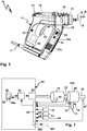
- a hand-held machine tool 10 has a housing 11, in the interior of which a drive train 20 is arranged.
- the hand machine tool 10 is, for example, a screwdriver, drill or both.
- the housing 11 can be comfortably gripped by an operator on a grip section 12.
- the drive train 20 is accommodated in an upper housing section 13, which runs like an pistol at an angle to the grip section 12.
- a front housing section 14 extends in front of the handle section 12, which can be gripped with one hand, for example, the handle section 12 and the housing section 14 being connected to one another by a lower housing section.
- a connection for a power cable 17 is located on this lower housing section, for example. Furthermore, it is possible to provide a rechargeable battery or another mobile energy storage device on this housing section or, as shown in the exemplary embodiment, in the region of the front housing section 14.
- a hand-held machine tool according to the invention it is possible for a hand-held machine tool according to the invention to be network-connected, that is to say, for example, to be connectable to an electrical supply network or to be a cordless machine, that is to say a mobile device.
- a switch 15 is provided on the handle section 12, with which a drive motor 16 of the hand machine tool 10 can be switched on or off. Furthermore, it is conceivable to use the switch 12 to set a speed of the hand machine tool 10.
- the tool 19 is, for example, a drill, a screwdriver bit or the like.
- another tool is of course expedient, for example a polishing tool, grinding tool or milling tool or the like.
- the drive motor 16 drives the tool holder 18 via a gear 30.
- a striking mechanism 21 can be connected between the transmission 30 and the tool holder 18, so that even a striking operation, for example for drilling holes, is possible with the hand machine tool 10.
- the drive motor 16 drives the transmission 30 using its motor shaft 22.
- the transmission 30 has a gear stage 31 with switchable first and second gear stages 41 and 42.
- the switching stage 31 is followed by a transmission stage 32 which, for example, further reduces an output speed of the switching stage 31.
- the translation stage 32 can be, for example, a reduction stage.
- the gear 30 is designed, for example, as a planetary gear.
- the transmission 30 can be driven via a drive shaft, for example the motor shaft 22.
- a drive wheel 33 is arranged on the motor shaft 22.
- the drive wheel 33 drives the switching stage 31.
- the drive wheel 33 forms a gear drive 25.
- the drive gear 33 is a sun gear 34 that drives transmission gears 35.
- the transmission gears 35 are, for example, planet gears 36 which are rotatably mounted on a planet carrier 37 on planet axes 40.
- the planet axes 40 are rotatably mounted on the planet carrier 37 or the planet gears 36 on the planet axes 40, for example.
- plain bearings, ball bearings or needle bearings or other roller bearings can be provided between the planet gears 36 and the planet axes 40 or the planet axes 40 and the planet carrier 37.
- the planet gears 36 mesh with the drive gear 33 with a first pitch circle diameter 38.
- a further, second pitch circle diameter 39 of the planet gears 36 is smaller than the pitch circle diameter 38, which contributes to a gear ratio.
- the planet gears 36 mesh with a ring gear 45 and a sun gear 46.
- the ring gear 45 is arranged radially on the outside with respect to the planet gears 36 and surrounds them in an annular manner.
- the sun gear 46 is provided, so to speak, in the center of the planet gears 36.
- the ring gear 45 is assigned to the first gear stage 41 and the sun gear 46 to the second gear stage 42.
- the ring gear 45 forms a locking gear element 43, the sun gear 46 a locking gear element 44.
- a respective locking gear element 43 or 44 is locked by locking devices 61 or 62 of a shift arrangement 60, it forms a support element for the transmission gears 35, in the present case the planet gears 36.
- the locking gear element 43 or 44 which is locked in each case, so to speak, switches the respective first and second gear stages 41, 42 active.
- a locking gear element 43, 44 is not locked by the associated locking device 61, 62, it can rotate freely so that it does not provide any support for the transmission wheels 35.
- An unlocked locking gear element 43, 44 switches the assigned first and second gear stage 41, 42 to inactive. Active and inactive should be understood that torque can be transmitted from the drive side to the output side.
- the locking gear element 43 is arranged with its radially outer circumference, so to speak, directly on or next to the locking device 61. This is not possible with the sun wheel 46, which is arranged centrally on the inside, so to speak. However, this also has a radially outer support region, namely in the form of a support wheel 47 which is connected to the sun wheel 46 or is in one piece. For example, the support gear 47 is connected to the sun gear 46 by a connecting washer and / or spokes 47A.
- the support wheel 46 and the locking gear element 43, ie the ring gear 45, have the same radial outer circumferences.
- a passage opening 48 is provided in the sun gear 46 or the locking gear element 44, through which the motor shaft 22 is connected to the drive gear 33.
- the switching stage 31 drives the transmission stage 32 via an output gear 49.
- the translation stage 32 is designed as a planetary stage 50.
- the driven wheel 49 is driven by the planet carrier 37 or in one piece with it.
- the driven wheel 49 projects in front of the planet carrier 37.
- the driven gear 49 mesh planet gears 51 which are rotatably supported on a planet carrier 52 by means of planetary axes 53.
- the driven gear 49 forms a sun gear for the planet gears 51.
- the planet gears 51 are rotatably mounted on the planet axes 53, for example.
- the cover 95 has a passage opening for the motor shaft 22 or another drive shaft.
- the gear 30 can advantageously be encapsulated, can have seals or the like, for example at an opening on the front 92, where the output shaft 55 penetrates the gear housing 90.
- the planet gears 36 and thus the transmission wheels 35 are not supported on the locking gear element 43 with respect to the gear housing 90, but can rotate freely.
- the gear stage 41 is thus inactive.
- the other gear stage 42 is then active, namely that its locking gear element 44 is supported by the locking device 62 with respect to the housing 90, so that the planet gears 36 can roll on the outer circumference of the sun gear 46 and thereby the power flow or the torque transmission from the gear drive 25 to Transmission output 26 extends over the gear stage 42.
- the locking device 62 releases the locking gear element 44, so that no power flow via the second gear stage 44 is possible.
- the sun gear 46 rotates freely.
- the other locking device 61 is then active, i.e. it locks the support element or locking gear element 43 assigned to it, namely the ring gear 45.
- the transmission gears 35 in this case the planet gears 36, can roll on the ring gear 45 which is stationary with respect to the gear housing 90 and thus a power flow or torque transmission from the gear drive 25 to Enable gearbox output 26.
- the gear stages 41, 42 each provide a torque ratio and speed change between the gear drive 25 on the one hand and the gear output 26 on the other hand. By simply reversing the direction of rotation of the drive motor 16, a different speed of the tool holder 18 and / or a different torque output on the tool holder 18 can be realized.
- the controller 80 changes the direction of rotation of the drive motor 16, for example, so that the transmission 30 shifts back from the second transmission stage to the first transmission stage, for example. However, if a speed of the drive motor 16 exceeds a predetermined amount, the controller 80 reverses the direction of rotation of the drive motor 16 so that the transmission 30 shifts from the first gear stage to the second gear stage so that the drive motor 16 can rotate at a lower speed.
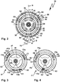
- the locking devices 61, 62 are, so to speak, supported in a sandwich-like manner between the locking gear elements 43 and 44 on the one hand and a housing section 94 of the gear housing 90.
- the locking devices 61, 62 form, so to speak, radially outer components of the transmission 30. Because the locking devices 61, 62 are arranged radially on the outside, they are also easily accessible for interventions from the outside, for example for changing over the respective blocking direction.
- the two locking devices 61, 62 which are switched off as freewheels, can be switched with respect to their locking direction and freewheeling direction.
- the locking devices 61, 62 comprise a common support ring 63, which could be called a freewheel ring.
- each locking device 61, 62 it would also be possible for each locking device 61, 62 to be designed as a separate freewheel device, i.e. that there are no common components.
- the support ring 63 is fixed in relation to the gear housing 90.
- support bodies 64 in particular bolts or the like, are positively inserted between the inner circumference of the gear housing 90, that is to say the housing section 94, and the outer circumference of the support ring 63 and hold the two components to one another in a form-fitting manner.
- the support ring 63 On its inner circumference, the support ring 63 has a plurality of, for example three, freewheel recesses 65 offset in terms of the angle of rotation, in each of which a locking element 68 or 69, in particular a roller or a pin, of a respective locking device 61 is guided under 62.
- the locking devices 61 have locking elements 68, 69 which are separate from one another, so that they can have opposite freewheeling directions in and locking directions.
- the locking elements 68, 69 are mounted between the outer circumferences of the locking gear elements 43, 44 and the inner circumference of the support ring 63 in the region of the respective freewheel recesses 65.
- the locking elements 68, 69 with respect to an axis of rotation D about which the locking gear elements 45, 46, namely the ring gear 45 and the combination of sun gear 46 and support gear 47 are rotated, are moved on the outer circumference of the respective locking gear element 43, 44, namely into or out of the area of the freewheel recesses 65, in clamping bevels or constrictions 66, 67.
- the respective locking device 61 or 62 is in the freewheel. However, if the locking elements 68, 69 are moved in the direction of the clamping slope or constrictions 66 or 67, the locking device 61, 62 is locked. The associated locking gear element 43, 44 is then blocked by the locking elements 68, 69 arranged on its outer circumference, which are located in one of the clamping bevels 66 or 67 and are supported on the support ring 63, with respect to rotatability about the axis of rotation D, so that the locking gear element 43, 44 can serve to support the planet gears 36 and thus the respective gear stage 41 or 42 is active.
- the blocking direction or freewheeling direction of a respective blocking device 61, 62 can be switched.
- a switching device 70 is provided which can be conveniently operated by an operator using a single, manual actuating element 71.
- the actuating element 71 is designed, for example, as a projection in front of a switching element 72, for example in the form of a ring, which can be rotated about the axis of rotation D.
- Pin-like guide elements 73 which are also referred to below as 73a and 73b, project from the switching element 72 in the direction of the blocking elements 68, 69, a respective blocking element 68, 69 being arranged between guide elements 73 which are opposite one another in pairs.
- the locking elements 69 are adjusted in the direction of the clamping slopes 66, so that the locking device 61 locks or blocks the support element or locking gear element 44 in a direction of rotation D1.
- the guide elements 73b hold the blocking elements 69 in the freewheel cutouts 65.
- the direction of rotation D2 therefore corresponds a freewheeling direction F1, the direction of rotation D1 a blocking direction S1 of the blocking device 62 in the position according to Figures 3 or 4 .
- a spring element 75 is provided in each case between the guide elements 73 and the locking elements 68, 69.
- the spring elements 75 load the locking elements 68, 69 in the direction of the locking position, i.e. in the direction of the clamping bevels 66, 67. So when the transmission 30 starts, so to speak, the locking elements 68, 69 are already loaded in the direction of the locking position, so that the locking function or as a support function of the locking gear elements 43, 44 is available as immediately as possible.
- the locking elements 68, 69 are expediently movably mounted, decoupled from one another.
- a decoupling ring 74 is arranged between the locking elements 68, 69 with respect to the axes of rotation D.
- the locking direction and the freewheeling direction of the locking devices 61, 62 can be switched in opposite directions, namely by the switching device 70.
- the actuating element 71 is actuated about the axis of rotation D
- the guide elements 73 also make this rotary movement, so that they proceed approximately from a central position Figure 2 are adjustable in this respect with respect to the axis of rotation D offset, for example a position for clockwise rotation or a position for counterclockwise rotation of the tool holder 18.
- the blocking direction S1 and the freewheeling direction F1 can be switched in opposite directions.
- the switching element 72 is created counterclockwise, so that the guide elements 73 are shown in broken lines in FIG Figure 3 and Figure 4 Assume the position shown, the guide elements 73a hold the blocking elements 69 in the freewheeling position, which, however, then corresponds to the direction of rotation D1.
- the locking gear element 44 can then rotate freely in the direction of rotation D1, in the opposite direction, in the direction of rotation D1, however, it is prevented from rotating by the locking device 62, that is, locked.
- Figure 3 is shown in dashed lines one of the locking elements 69 in a locking position, in which is applied to the clamping slope 67, which is a locking direction S2 corresponds.
- the position of the guide elements 73a according to Figure 4 in dashed lines corresponds to a freewheeling position Figure 2 .
- the controller 80 adjusts the direction of rotation of the drive motor 16 depending on the position of the switching device 70 for clockwise or counterclockwise rotation, so that it switches after switching from clockwise rotation to counterclockwise rotation or vice versa in the gear stage assumed before the direction of rotation was switched 41 or 42 starts up.
- a sensor 85 is arranged on the switching device 70 in order to detect its respective switching position.
- the sensor 85 is, for example, an electrical contact, a contactless contact or the like.
- an inductive, optical or capacitive measuring element can be provided as a sensor, but also an electrical contact switch or the like.
- the first gear stage 41 represents a minus gear
- the second gear stage 42 a positive gear, so that the gear stages 41 and 42 can be switched by a simple reversal of the direction of rotation of the drive motor 16 in the transmission 30, but no reversal of the direction of rotation is connected to the transmission output 26.
- This concept can also be used for types of gears that are not designed as planetary gears Figures 8 and 9 still becomes clear.
- a drive train 120 ( Figure 8 ) drives the drive motor 16, for example via a motor shaft 122, which also represents a gear drive 125, a first gear stage 141 and a second gear stage 142 of a gear 130.
- Both switching stages 141 and 142 cause a change in speed and torque between the gear drive 125 on the one hand and the gear output 126 on the other, on which the tool holder 18 can be arranged directly, for example.
- a further gear stage is arranged on the gear output 126 or that this gear output 126 is arranged on a gear stage, not shown, for example a reduction stage.
- Locking devices 161, 162 are arranged on the motor shaft 122, which in the area of the transmission 120 could easily also be referred to as a transmission shaft. In the simplest case, these could be freewheels, but also switchable locking devices whose locking direction and release direction of rotation or freewheeling direction can be switched, for example by an electrical actuator that can be controlled by the controller 80.
- the locking devices 161 and 162 are provided between locking gear elements 143 and 144. If a respective locking device 161 or 162 is locked, it takes its assigned locking gear element 143, 144. In an opposite direction of rotation, however, locking gear element 143 or 144 can be rotated on locking device 161 or 162, that is, it is not blocked or locked.
- the locking gear element 143 is, for example, a gearwheel or drive wheel 146 which meshes with a transmission wheel 135.
- the transmission wheel 135 is rotatably connected to an output shaft 155 which has the tool holder 18 at its free end or drives it via a gear, not shown.
- the gear stage 141 represents a so-called minus gear.
- the locking gear element 144 is, for example, a ring gear 145 , with the inner circumference of the transmission wheel 135 meshes. A positive transmission is thus realized.
- the ring gear 145 has radially inward spokes 146 or other connecting elements which are connected to the locking device 162 or have a radially inner support wheel 147 which can be locked by the locking device 162.
- the transmission 130 is also very compact, because both locking gear elements 143, 144 act directly on one and the same drive wheel 135.
- a switching device 170 is shown as an example of a manual or electrically actuated switching device for switching the blocking directions or free-running direction in the blocking devices 161 and 161.
- Their actuating element 171 acts, for example, on blocking elements 168 and 169 of the blocking devices 161, 162 similarly to the guide elements 73 of the switching device 70.
- the switching device 171 must switch in opposite directions, since the blocking gear elements 143, 144 must have an opposite freewheeling direction, so that gear stage 141 and the other time, gear stage 142 is inactive.
- One possibility for such an actuation is e.g. in that the actuating element 171 is rotatably mounted about an axis of rotation 176 so that it can act in opposite directions on the locking elements 168, 169.
- a gear 230 is provided, which is also designed so that there is no reversal of the direction of rotation between its gear drive 225 and its gear output 226 when the drive motor 16 rotates in opposite directions.
- locking devices 261, 262, which are assigned to gear stages 241 and 242 are arranged coaxially and next to one another on a motor shaft 222, which can also represent a transmission shaft.
- the locking devices 261 and 262 carry locking gear elements 243, 244 on their outer circumference, of which, when the motor shaft 222 is rotated in one direction of rotation, a locking gear element 243 is taken along, the other locking gear element 244 rotates freely, while in the opposite direction of rotation the locking gear element 243 is freely rotatable is while the ratchet element 244 is driven by the motor shaft 222.
- the locking gear elements 243, 244 are, for example, gears.
- the locking gear elements 243, 244 are designed, for example, as drive wheels 245, 246.
- the drive wheel 245 drives a transmission wheel 235 via a transmission wheel 248, which is provided for driving the tool holder 18.
- the transmission wheel 235 is arranged in a rotationally fixed manner on an output shaft 255.
- the tool holder 18 is provided directly on the output shaft 255.
- the output shaft 255 could, however, also be configured to drive a further gear stage and / or an impact mechanism.
- Another transmission wheel 247 is also non-rotatably connected to the output shaft 255 and serves to drive it.
- a first gear stage 241 is active, which altogether implements a so-called positive gear.
- the transmission wheel 248 realizes with the blocking gear element 243 and the drive wheel 235 a minus gear, so that a plus gear is present overall.
- the second gear stage 242 is designed as a minus gear. In any case, the direction of rotation of the transmission output 226 is always the same in the case of opposite directions of rotation of the transmission drive 225.
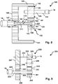
- a powertrain 320 according to Figures 10 and 11 comprises a transmission 330, which is constructed similarly to the transmission 30 or its switching stage 31 with respect to a switching stage 331, but the actuation concept (with a switching device 370) is different for a switching arrangement 360, which corresponds functionally to the switching arrangement 60, and the Output side of the transmission 330, where instead of a simple planetary stage or a simple reduction gear as in the embodiment according to Figures 5 and 6 a switchable transmission arrangement 350 is provided.
- the same or similar components in the embodiment according to Figures 5 and 6 as well as the other embodiment Figures 10 and 11 are present, they are provided with the same reference numbers, but in order to clarify differences, in some cases with 300 increased reference numbers.
- the gear stage 331 drives a gear stage 332 with its gear output 25, which can, but does not have to, work as a reduction stage in the sense of a speed reduction.
- the drive motor 16 drives a drive wheel 333 via the motor shaft 22.
- the drive gear 333 forms a sun gear 334, which meshes with planet gears 336.
- the planet gears 336 advantageously form transmission gears 35.
- the planet gears 336 are rotatably mounted on a planet carrier 337.
- planetary axes 40 are rotatably supported on planet carrier 37, or planetary carriers 336 are rotatably supported on planetary axes 40.
- the planet gears 336 have different pitch circle diameters 38, 39 like the planet gears 36. With the pitch circle diameter 38, the planet gears 336 mesh with the sun gear 334, while the smaller pitch circle diameter 39 provides that the planet gears 336 come into engagement with a ring gear 345, that is, with it can comb or take the ring gear 345 with it.
- the gear stage 331 has a first gear stage 341 (corresponding to the gear stage 41) and a second gear stage 342 (corresponding to the gear stage 42), between which the gear stage 331 can be switched by reversing the direction of rotation of the drive motor 16.
- the planet gears 336 are also supported, so to speak, radially on the inside, namely can roll on a sun gear 346, which forms part of a locking gear element 344.
- the locking gear element 344 corresponds to the locking gear element 44 and has a passage opening 48 for the motor shaft 22.
- the switching arrangement 360 comprises a locking device 361 for locking or unlocking the locking gear element 343 and a locking device 362 for locking or unlocking the locking gear element 344.
- locking elements 368, 369 are supported on a support ring or freewheel ring 363 (similar to components 68, 69 and 63) and are preferably by in Figure 10 visible spring elements 375 (corresponding to the spring elements 75).
- the actuating element 371 projects radially outward in front of a gearbox housing 390 of the gearbox 330 and can therefore be gripped comfortably by the operator.
- the actuating element 371 is preferably rotatably mounted on the support ring or freewheel ring 363 or extends through it.
- the actuating element 371 is provided on a housing section 394 of the transmission housing 390, in which the switching stage 331 is accommodated.
- the actuating element 371 is rotatably connected to the switching element 372.
- a section 374 of the rod-shaped or ring-shaped actuating element 371, for example, is coupled to the switching element 372.
- the switching element 372 is ring-shaped, for example, similar to the switching element 72.
- the shift element 372 is, however, arranged between the gear stages 341, 342 and between the locking gear elements 343, 344.
- a projection 372a engages in an intermediate section between the ring gear 345 and the support wheel 347 of the locking gear element 344.
- the transmission 390 is also closed on its side facing the drive motor 16 by a cover, here a cover 395.
- a cover 395 On a side facing away from the cover 395, next to the housing section 394, there is a further housing section 393 which receives the gear arrangement 350, that is to say the gear stage 332.
- the housing section 393 is closed by a cover 391, on the front or front side 392 of which the output shaft 55 is coupled to the tool holder 18.
- the tool shaft 18 is driven by the gear stage or switching stage 332, which in turn is coupled to the gear output 26 of the switching stage 31.
- the transmission output 26 comprises an output gear 349, which is, for example, firmly connected to the planet carrier 337, for example in one piece with it.
- the driven gear 349 forms a sun gear with which planet gears 351 of the gear arrangement 350 mesh.
- the planet gears 351 are rotatable with respect to a planet carrier 352, for example by being rotatably mounted on planetary axes 353 or by the planetary axes 353 being rotatably supported on planetary carrier 352.
- Shown switching position of the gear arrangement 350 couples a ratchet wheel 354, for example a ring gear, the gear arrangement 350 connects the planet gears 351 to the planet carrier 337 in a rotationally fixed manner.
- the planet carrier 337 has, for example on its outer circumference, a toothing 337a which can engage with an internal toothing of the switching wheel 354.
- a respective planet gear 351 is also in engagement with this toothing or a toothing lying next to it.
- the planet gears 351 mesh with the internal toothing of the ratchet wheel 354, so they roll on this.
- the ratchet wheel 354 in turn is fixed in a rotationally fixed manner with respect to the transmission housing, for example by means of an external toothing 354a of the ratchet wheel 354 which engages with an internal toothing 354b on the housing 390, for example the cover 391.
- the internal toothing 354b is radially on the inside
- the external toothing 354a is radially on the outside.
- a switching position can accordingly Figure 10 can be set, in which the output shaft 55 and thus the tool on the tool holder 18 rotates at the speed of the planet carrier 337 or the transmission output 26, and a switching position accordingly Figure 11 in which a reduction stage is implemented.
- the sun gear or drive gear 349 drives the planet gears 351, which in turn roll on the ring gear or gear wheel 354, thus reducing the speed and simultaneously increasing the torque on the output.
- the switchable transmission arrangement 350 can be switched manually, for example by an actuating element 310, which is displaceably mounted in a receptacle 311 of the transmission housing 390.
- the actuating element 310 is coupled in motion by means of a coupling element 312 to the ratchet wheel 354, but could also be arranged fixedly on the ratchet wheel 354.
- the coupling element 312 comprises, for example, pins, brackets or the like other components which enable a power transmission from an outside of the gear housing 390 into its interior, where the switching wheel 354 is arranged.
- the receptacle 311 forms a sliding bearing or a sliding receptacle in which the actuating element 310 is accommodated in a linearly displaceable manner.
- the actuating element 310 is motion-coupled or in one piece with a manually graspable actuating handle 313, for example a ring or slide.
- the actuating handle 313 projects, for example, in front of the housing 11 of the hand machine tool 10, and is therefore easy to grasp.
- An alternative or supplementary drive concept or actuation concept for the switching wheel 354, and consequently a concept for switching the transmission arrangement 350 is represented by an actuator 387, for example an electromagnet, an electric motor or the like (a pneumatic drive is also possible).
- the actuator 387 is designed and provided to adjust the ratchet wheel 354, that is to say a shift element of the transmission arrangement 350, between at least two shift positions.
- actuator 387 can switch wheel 354 between the switch positions according to FIG Figures 10 and 11 adjust back and forth.
- the actuator 387 is controlled, for example, via an electrical switch 24a on the housing 11 of the hand machine tool 10.
- the actuator 387 is accommodated in a protected manner in the interior of the transmission housing 390.
- the representation of the actuator 387 is to be understood as an example.
- the controller 80 is preferably designed to control the actuator 387. For example, it has a switching output 388 for switching the actuator 387. In Figure 7 is that indicated.
- the controller 80 can thus, for example, automatically shift the transmission stage or shift stage 331, advantageously also the shiftable transmission arrangement 350 or the shift stage 332.
- a four-speed transmission can thus be implemented overall, which is even fully automatic works.
- sensors that interact with the controller 80 can also be provided at the output area.
- a sensor 87 for detecting the speed and / or torque and / or direction of rotation or the like for example a tachometer, a torque detection, can be provided on the tool shaft or output shaft 55.
- a sensor 88 for example an optical sensor, a Hall sensor or the like, can detect, for example, its torque and / or direction of rotation and / or speed in the drive motor 16.
- a sensor 89 in particular for speed detection and / or torque detection and / or rotation direction detection, can also be provided at the input of the transmission 30, 330, for example on the motor shaft 22.
- the sensors 87, 88, 89 report their respective sensor signals via the input interface 84 to the controller 80, which uses the software program 86, for example, to set the speed and / or direction of rotation of the drive motor 16 in order to shift the transmission 30, 330 in this way.
- the controller 80 can control the actuator 387.
- the sensor signals of the sensors 87, 89, 88 can also be used to regulate and / or control the drive motor 16 and in particular also to shift the transmission 330, in particular its gear stage 332.
- an operator can, for example, specify a desired maximum speed or target speed SD of the output shaft 55.
- a desired maximum speed or target speed SD of the output shaft 55 For example, the operator can specify a maximum speed of 2000 to 4000 revolutions / min for drilling operations and a maximum speed of 500 to 2000 revolutions / min for screwing operations.
- an optionally available torque setting element 24 for example a rotatable adjusting element, a slide or the like
- the operator can, for example, specify a desired maximum torque or target torque SM on the output shaft 55.
- damage to screws or the like can be prevented, for example.
- Speed control or torque control can be advantageous, for example, in a milling machine or saw.
- a touch-sensitive display can also be provided, which displays the set values SM and / or SD.
- a control module 86a of the software program 86 can, for example, use the maximum values or target values SM and / or SD and the feedback of the set values, namely the actual values which the sensors 87, 88, 89 deliver, the drive motor 16 and / or control the output stage 83 and / or rules. Furthermore, the control module 86a can also control the actuator 387 in accordance with these values via the switching output 388 to switch the gear stage 332.
- the controller 80 controls the actuator 387 to shift the transmission stage 332 from the shift position in which the shift stage 332 does not reduce the speed relative to the transmission output 26 ( Figure 10 ), in the shift position in which gear stage 332 acts as a reduction gear ( Figure 11 ), ie the position at which the planet gears 351 roll in the ring gear 354.
- the planetary axes 353 or 53 can be components of a spindle stop, i.e. that a rotation lock on the output side of the gear 30, 330 can be easily implemented at this point.
Landscapes
- Engineering & Computer Science (AREA)
- Mechanical Engineering (AREA)
- Structure Of Transmissions (AREA)
- Toys (AREA)
Applications Claiming Priority (3)
| Application Number | Priority Date | Filing Date | Title |
|---|---|---|---|
| DE102015110504.7A DE102015110504A1 (de) | 2015-06-30 | 2015-06-30 | Hand-Werkzeugmaschine |
| PCT/EP2016/065048 WO2017001423A1 (fr) | 2015-06-30 | 2016-06-28 | Machine-outil portative |
| EP16733490.3A EP3317051B1 (fr) | 2015-06-30 | 2016-06-28 | Machine-outil portative |
Related Parent Applications (3)
| Application Number | Title | Priority Date | Filing Date |
|---|---|---|---|
| PCT/EP2016/065048 Previously-Filed-Application WO2017001423A1 (fr) | 2015-06-30 | 2016-06-28 | Machine-outil portative |
| EP16733490.3A Division EP3317051B1 (fr) | 2015-06-30 | 2016-06-28 | Machine-outil portative |
| EP16733490.3A Division-Into EP3317051B1 (fr) | 2015-06-30 | 2016-06-28 | Machine-outil portative |
Publications (2)
| Publication Number | Publication Date |
|---|---|
| EP3674038A1 true EP3674038A1 (fr) | 2020-07-01 |
| EP3674038B1 EP3674038B1 (fr) | 2021-06-30 |
Family
ID=56292708
Family Applications (2)
| Application Number | Title | Priority Date | Filing Date |
|---|---|---|---|
| EP19219478.5A Active EP3674038B1 (fr) | 2015-06-30 | 2016-06-28 | Machine-outil manuelle |
| EP16733490.3A Active EP3317051B1 (fr) | 2015-06-30 | 2016-06-28 | Machine-outil portative |
Family Applications After (1)
| Application Number | Title | Priority Date | Filing Date |
|---|---|---|---|
| EP16733490.3A Active EP3317051B1 (fr) | 2015-06-30 | 2016-06-28 | Machine-outil portative |
Country Status (4)
| Country | Link |
|---|---|
| EP (2) | EP3674038B1 (fr) |
| CN (1) | CN107980019B (fr) |
| DE (1) | DE102015110504A1 (fr) |
| WO (1) | WO2017001423A1 (fr) |
Families Citing this family (4)
| Publication number | Priority date | Publication date | Assignee | Title |
|---|---|---|---|---|
| EP3335839B1 (fr) * | 2016-12-16 | 2019-05-01 | Festool GmbH | Machine-outil portative |
| CN109849177A (zh) * | 2019-04-10 | 2019-06-07 | 陈晓清 | 一种混凝土管抹光增强装置 |
| JP7480173B2 (ja) * | 2019-05-02 | 2024-05-09 | フェスツール ゲーエムベーハー | 手持ち工作機械用アタッチメント装置 |
| SE2130369A1 (en) * | 2021-12-17 | 2023-06-18 | Atlas Copco Ind Technique Ab | Power tool and load-responsive power transmission for a power tool |
Citations (4)
| Publication number | Priority date | Publication date | Assignee | Title |
|---|---|---|---|---|
| FR2542655A1 (fr) * | 1983-03-18 | 1984-09-21 | Renault | Broche de vissage |
| DE3329295A1 (de) * | 1983-08-12 | 1985-02-28 | Alfing Montagetechnik GmbH, 7080 Aalen | Motorisch angetriebenes schraubwerkzeug |
| WO2005051606A1 (fr) * | 2003-11-27 | 2005-06-09 | Robert Bosch Gmbh | Perçeuse-visseuse manuelle |
| EP2685130A1 (fr) * | 2012-07-10 | 2014-01-15 | Metabowerke GmbH | Agencement dýengrenage |
Family Cites Families (8)
| Publication number | Priority date | Publication date | Assignee | Title |
|---|---|---|---|---|
| DE3529992A1 (de) | 1985-08-22 | 1987-02-26 | Volkswagen Ag | Antrieb fuer schrauber |
| DE19625850B4 (de) * | 1995-06-27 | 2008-01-31 | Matsushita Electric Works, Ltd., Kadoma | Planetengetriebe |
| DE19619428B4 (de) * | 1996-05-14 | 2005-11-10 | Eduard Gasinski | Handgeführte Kombinationswerkzeugmaschine mit Bohrmaschinen- und Stichsägenfunktion |
| DE102004018025B4 (de) * | 2004-04-14 | 2008-01-31 | Metabowerke Gmbh | Elektrohandwerkzeug mit einer Mitnahme-/Blockiereinrichtung |
| DE102008043795A1 (de) * | 2008-11-17 | 2010-05-20 | Robert Bosch Gmbh | Schaltbares Planetengetriebe in einer Handwerkzeugmaschine |
| EP2529895A4 (fr) * | 2010-01-25 | 2016-06-22 | Makita Corp | Outil motorisé |
| CN103846879B (zh) * | 2012-12-07 | 2016-03-16 | 苏州宝时得电动工具有限公司 | 动力工具 |
| DE102013212196A1 (de) * | 2013-06-26 | 2014-12-31 | Robert Bosch Gmbh | Handwerkzeugmaschine mit einer Spindellockvorrichtung |
-
2015
- 2015-06-30 DE DE102015110504.7A patent/DE102015110504A1/de not_active Withdrawn
-
2016
- 2016-06-28 EP EP19219478.5A patent/EP3674038B1/fr active Active
- 2016-06-28 EP EP16733490.3A patent/EP3317051B1/fr active Active
- 2016-06-28 WO PCT/EP2016/065048 patent/WO2017001423A1/fr active Application Filing
- 2016-06-28 CN CN201680037176.1A patent/CN107980019B/zh active Active
Patent Citations (4)
| Publication number | Priority date | Publication date | Assignee | Title |
|---|---|---|---|---|
| FR2542655A1 (fr) * | 1983-03-18 | 1984-09-21 | Renault | Broche de vissage |
| DE3329295A1 (de) * | 1983-08-12 | 1985-02-28 | Alfing Montagetechnik GmbH, 7080 Aalen | Motorisch angetriebenes schraubwerkzeug |
| WO2005051606A1 (fr) * | 2003-11-27 | 2005-06-09 | Robert Bosch Gmbh | Perçeuse-visseuse manuelle |
| EP2685130A1 (fr) * | 2012-07-10 | 2014-01-15 | Metabowerke GmbH | Agencement dýengrenage |
Also Published As
| Publication number | Publication date |
|---|---|
| EP3317051A1 (fr) | 2018-05-09 |
| CN107980019A (zh) | 2018-05-01 |
| EP3674038B1 (fr) | 2021-06-30 |
| WO2017001423A1 (fr) | 2017-01-05 |
| DE102015110504A1 (de) | 2017-01-19 |
| EP3317051B1 (fr) | 2020-02-12 |
| CN107980019B (zh) | 2021-10-15 |
Similar Documents
| Publication | Publication Date | Title |
|---|---|---|
| EP2661336B1 (fr) | Transmission à trains épicycloïdaux pour une machine-outil | |
| EP3317051B1 (fr) | Machine-outil portative | |
| EP2358502B1 (fr) | Engrenage planétaire commutable dans une machine-outil portative | |
| DE102012211914B4 (de) | Handwerkzeugmaschine mit einem Planetengetriebe | |
| EP1886769B1 (fr) | Machine-outil dotée d'un train épicycloïdal à plusieurs niveaux | |
| EP3676053B1 (fr) | Machine-outil portative | |
| DE102012213724B4 (de) | Planetengetriebe für eine Handwerkzeugmaschine | |
| DE102011004126A1 (de) | Handwerkzeugmaschine mit einem Untersetzungsgetriebe | |
| EP2480372B1 (fr) | Dispositif d'entraînement | |
| DE102009047130A1 (de) | Antriebseinrichtung eines Fahrzeug-Bauteils, insbesondere einer Karosserieklappe | |
| WO2019042908A1 (fr) | Machine-outil portative | |
| EP1886768B1 (fr) | Machine-outil dotée d'engrenages à plusieurs étapes | |
| EP1313965A1 (fr) | Dispositif permettant de transformer un mouvement de rotation en mouvement axial | |
| EP2095909A1 (fr) | Train épicycloïdal pour une machine-outil électrique et machine-outil portative électrique | |
| DE102016221297A1 (de) | Schaltbares Planetengetriebe | |
| EP2180979B1 (fr) | Outil à main électrique | |
| EP2316620B1 (fr) | Outil manuel | |
| EP3335839B1 (fr) | Machine-outil portative | |
| DE102008052546A1 (de) | Getriebemotor, Getriebesystem und Verfahren zum Betrieb eines Systems | |
| WO2010102684A1 (fr) | Dispositif de machine-outil | |
| DE102018120202A1 (de) | Aktuatoranordnung | |
| DE202009013116U1 (de) | Handgeführtes Werkzeuggerät |
Legal Events
| Date | Code | Title | Description |
|---|---|---|---|
| PUAI | Public reference made under article 153(3) epc to a published international application that has entered the european phase |
Free format text: ORIGINAL CODE: 0009012 |
|
| STAA | Information on the status of an ep patent application or granted ep patent |
Free format text: STATUS: THE APPLICATION HAS BEEN PUBLISHED |
|
| AC | Divisional application: reference to earlier application |
Ref document number: 3317051 Country of ref document: EP Kind code of ref document: P |
|
| AK | Designated contracting states |
Kind code of ref document: A1 Designated state(s): AL AT BE BG CH CY CZ DE DK EE ES FI FR GB GR HR HU IE IS IT LI LT LU LV MC MK MT NL NO PL PT RO RS SE SI SK SM TR |
|
| STAA | Information on the status of an ep patent application or granted ep patent |
Free format text: STATUS: REQUEST FOR EXAMINATION WAS MADE |
|
| 17P | Request for examination filed |
Effective date: 20201215 |
|
| RBV | Designated contracting states (corrected) |
Designated state(s): AL AT BE BG CH CY CZ DE DK EE ES FI FR GB GR HR HU IE IS IT LI LT LU LV MC MK MT NL NO PL PT RO RS SE SI SK SM TR |
|
| GRAP | Despatch of communication of intention to grant a patent |
Free format text: ORIGINAL CODE: EPIDOSNIGR1 |
|
| STAA | Information on the status of an ep patent application or granted ep patent |
Free format text: STATUS: GRANT OF PATENT IS INTENDED |
|
| INTG | Intention to grant announced |
Effective date: 20210303 |
|
| GRAS | Grant fee paid |
Free format text: ORIGINAL CODE: EPIDOSNIGR3 |
|
| GRAA | (expected) grant |
Free format text: ORIGINAL CODE: 0009210 |
|
| STAA | Information on the status of an ep patent application or granted ep patent |
Free format text: STATUS: THE PATENT HAS BEEN GRANTED |
|
| AC | Divisional application: reference to earlier application |
Ref document number: 3317051 Country of ref document: EP Kind code of ref document: P |
|
| AK | Designated contracting states |
Kind code of ref document: B1 Designated state(s): AL AT BE BG CH CY CZ DE DK EE ES FI FR GB GR HR HU IE IS IT LI LT LU LV MC MK MT NL NO PL PT RO RS SE SI SK SM TR |
|
| REG | Reference to a national code |
Ref country code: CH Ref legal event code: EP |
|
| REG | Reference to a national code |
Ref country code: DE Ref legal event code: R096 Ref document number: 502016013335 Country of ref document: DE Ref country code: AT Ref legal event code: REF Ref document number: 1405912 Country of ref document: AT Kind code of ref document: T Effective date: 20210715 |
|
| REG | Reference to a national code |
Ref country code: IE Ref legal event code: FG4D Free format text: LANGUAGE OF EP DOCUMENT: GERMAN |
|
| REG | Reference to a national code |
Ref country code: LT Ref legal event code: MG9D |
|
| PG25 | Lapsed in a contracting state [announced via postgrant information from national office to epo] |
Ref country code: FI Free format text: LAPSE BECAUSE OF FAILURE TO SUBMIT A TRANSLATION OF THE DESCRIPTION OR TO PAY THE FEE WITHIN THE PRESCRIBED TIME-LIMIT Effective date: 20210630 Ref country code: HR Free format text: LAPSE BECAUSE OF FAILURE TO SUBMIT A TRANSLATION OF THE DESCRIPTION OR TO PAY THE FEE WITHIN THE PRESCRIBED TIME-LIMIT Effective date: 20210630 Ref country code: BG Free format text: LAPSE BECAUSE OF FAILURE TO SUBMIT A TRANSLATION OF THE DESCRIPTION OR TO PAY THE FEE WITHIN THE PRESCRIBED TIME-LIMIT Effective date: 20210930 |
|
| REG | Reference to a national code |
Ref country code: NL Ref legal event code: MP Effective date: 20210630 |
|
| PG25 | Lapsed in a contracting state [announced via postgrant information from national office to epo] |
Ref country code: RS Free format text: LAPSE BECAUSE OF FAILURE TO SUBMIT A TRANSLATION OF THE DESCRIPTION OR TO PAY THE FEE WITHIN THE PRESCRIBED TIME-LIMIT Effective date: 20210630 Ref country code: SE Free format text: LAPSE BECAUSE OF FAILURE TO SUBMIT A TRANSLATION OF THE DESCRIPTION OR TO PAY THE FEE WITHIN THE PRESCRIBED TIME-LIMIT Effective date: 20210630 Ref country code: LV Free format text: LAPSE BECAUSE OF FAILURE TO SUBMIT A TRANSLATION OF THE DESCRIPTION OR TO PAY THE FEE WITHIN THE PRESCRIBED TIME-LIMIT Effective date: 20210630 Ref country code: NO Free format text: LAPSE BECAUSE OF FAILURE TO SUBMIT A TRANSLATION OF THE DESCRIPTION OR TO PAY THE FEE WITHIN THE PRESCRIBED TIME-LIMIT Effective date: 20210930 Ref country code: GR Free format text: LAPSE BECAUSE OF FAILURE TO SUBMIT A TRANSLATION OF THE DESCRIPTION OR TO PAY THE FEE WITHIN THE PRESCRIBED TIME-LIMIT Effective date: 20211001 |
|
| PG25 | Lapsed in a contracting state [announced via postgrant information from national office to epo] |
Ref country code: SK Free format text: LAPSE BECAUSE OF FAILURE TO SUBMIT A TRANSLATION OF THE DESCRIPTION OR TO PAY THE FEE WITHIN THE PRESCRIBED TIME-LIMIT Effective date: 20210630 Ref country code: EE Free format text: LAPSE BECAUSE OF FAILURE TO SUBMIT A TRANSLATION OF THE DESCRIPTION OR TO PAY THE FEE WITHIN THE PRESCRIBED TIME-LIMIT Effective date: 20210630 Ref country code: ES Free format text: LAPSE BECAUSE OF FAILURE TO SUBMIT A TRANSLATION OF THE DESCRIPTION OR TO PAY THE FEE WITHIN THE PRESCRIBED TIME-LIMIT Effective date: 20210630 Ref country code: CZ Free format text: LAPSE BECAUSE OF FAILURE TO SUBMIT A TRANSLATION OF THE DESCRIPTION OR TO PAY THE FEE WITHIN THE PRESCRIBED TIME-LIMIT Effective date: 20210630 Ref country code: NL Free format text: LAPSE BECAUSE OF FAILURE TO SUBMIT A TRANSLATION OF THE DESCRIPTION OR TO PAY THE FEE WITHIN THE PRESCRIBED TIME-LIMIT Effective date: 20210630 Ref country code: PT Free format text: LAPSE BECAUSE OF FAILURE TO SUBMIT A TRANSLATION OF THE DESCRIPTION OR TO PAY THE FEE WITHIN THE PRESCRIBED TIME-LIMIT Effective date: 20211102 Ref country code: RO Free format text: LAPSE BECAUSE OF FAILURE TO SUBMIT A TRANSLATION OF THE DESCRIPTION OR TO PAY THE FEE WITHIN THE PRESCRIBED TIME-LIMIT Effective date: 20210630 Ref country code: SM Free format text: LAPSE BECAUSE OF FAILURE TO SUBMIT A TRANSLATION OF THE DESCRIPTION OR TO PAY THE FEE WITHIN THE PRESCRIBED TIME-LIMIT Effective date: 20210630 |
|
| PG25 | Lapsed in a contracting state [announced via postgrant information from national office to epo] |
Ref country code: PL Free format text: LAPSE BECAUSE OF FAILURE TO SUBMIT A TRANSLATION OF THE DESCRIPTION OR TO PAY THE FEE WITHIN THE PRESCRIBED TIME-LIMIT Effective date: 20210630 |
|
| REG | Reference to a national code |
Ref country code: DE Ref legal event code: R097 Ref document number: 502016013335 Country of ref document: DE |
|
| PG25 | Lapsed in a contracting state [announced via postgrant information from national office to epo] |
Ref country code: DK Free format text: LAPSE BECAUSE OF FAILURE TO SUBMIT A TRANSLATION OF THE DESCRIPTION OR TO PAY THE FEE WITHIN THE PRESCRIBED TIME-LIMIT Effective date: 20210630 |
|
| PLBE | No opposition filed within time limit |
Free format text: ORIGINAL CODE: 0009261 |
|
| STAA | Information on the status of an ep patent application or granted ep patent |
Free format text: STATUS: NO OPPOSITION FILED WITHIN TIME LIMIT |
|
| PG25 | Lapsed in a contracting state [announced via postgrant information from national office to epo] |
Ref country code: AL Free format text: LAPSE BECAUSE OF FAILURE TO SUBMIT A TRANSLATION OF THE DESCRIPTION OR TO PAY THE FEE WITHIN THE PRESCRIBED TIME-LIMIT Effective date: 20210630 |
|
| 26N | No opposition filed |
Effective date: 20220331 |
|
| PG25 | Lapsed in a contracting state [announced via postgrant information from national office to epo] |
Ref country code: IT Free format text: LAPSE BECAUSE OF FAILURE TO SUBMIT A TRANSLATION OF THE DESCRIPTION OR TO PAY THE FEE WITHIN THE PRESCRIBED TIME-LIMIT Effective date: 20210630 |
|
| PG25 | Lapsed in a contracting state [announced via postgrant information from national office to epo] |
Ref country code: MC Free format text: LAPSE BECAUSE OF FAILURE TO SUBMIT A TRANSLATION OF THE DESCRIPTION OR TO PAY THE FEE WITHIN THE PRESCRIBED TIME-LIMIT Effective date: 20210630 |
|
| REG | Reference to a national code |
Ref country code: CH Ref legal event code: PL |
|
| REG | Reference to a national code |
Ref country code: BE Ref legal event code: MM Effective date: 20220630 |
|
| PG25 | Lapsed in a contracting state [announced via postgrant information from national office to epo] |
Ref country code: LU Free format text: LAPSE BECAUSE OF NON-PAYMENT OF DUE FEES Effective date: 20220628 Ref country code: LT Free format text: LAPSE BECAUSE OF FAILURE TO SUBMIT A TRANSLATION OF THE DESCRIPTION OR TO PAY THE FEE WITHIN THE PRESCRIBED TIME-LIMIT Effective date: 20210630 Ref country code: LI Free format text: LAPSE BECAUSE OF NON-PAYMENT OF DUE FEES Effective date: 20220630 Ref country code: IE Free format text: LAPSE BECAUSE OF NON-PAYMENT OF DUE FEES Effective date: 20220628 Ref country code: CH Free format text: LAPSE BECAUSE OF NON-PAYMENT OF DUE FEES Effective date: 20220630 |
|
| PG25 | Lapsed in a contracting state [announced via postgrant information from national office to epo] |
Ref country code: BE Free format text: LAPSE BECAUSE OF NON-PAYMENT OF DUE FEES Effective date: 20220630 |
|
| P01 | Opt-out of the competence of the unified patent court (upc) registered |
Effective date: 20230517 |
|
| PGFP | Annual fee paid to national office [announced via postgrant information from national office to epo] |
Ref country code: FR Payment date: 20230502 Year of fee payment: 8 Ref country code: DE Payment date: 20230506 Year of fee payment: 8 |
|
| REG | Reference to a national code |
Ref country code: AT Ref legal event code: MM01 Ref document number: 1405912 Country of ref document: AT Kind code of ref document: T Effective date: 20220628 |
|
| PG25 | Lapsed in a contracting state [announced via postgrant information from national office to epo] |
Ref country code: AT Free format text: LAPSE BECAUSE OF NON-PAYMENT OF DUE FEES Effective date: 20220628 |
|
| PGFP | Annual fee paid to national office [announced via postgrant information from national office to epo] |
Ref country code: GB Payment date: 20230502 Year of fee payment: 8 |
|
| PG25 | Lapsed in a contracting state [announced via postgrant information from national office to epo] |
Ref country code: MK Free format text: LAPSE BECAUSE OF FAILURE TO SUBMIT A TRANSLATION OF THE DESCRIPTION OR TO PAY THE FEE WITHIN THE PRESCRIBED TIME-LIMIT Effective date: 20210630 Ref country code: CY Free format text: LAPSE BECAUSE OF FAILURE TO SUBMIT A TRANSLATION OF THE DESCRIPTION OR TO PAY THE FEE WITHIN THE PRESCRIBED TIME-LIMIT Effective date: 20210630 |