EP3674038A1 - Hand tool machine - Google Patents
Hand tool machine Download PDFInfo
- Publication number
- EP3674038A1 EP3674038A1 EP19219478.5A EP19219478A EP3674038A1 EP 3674038 A1 EP3674038 A1 EP 3674038A1 EP 19219478 A EP19219478 A EP 19219478A EP 3674038 A1 EP3674038 A1 EP 3674038A1
- Authority
- EP
- European Patent Office
- Prior art keywords
- gear
- locking
- stage
- transmission
- machine tool
- Prior art date
- Legal status (The legal status is an assumption and is not a legal conclusion. Google has not performed a legal analysis and makes no representation as to the accuracy of the status listed.)
- Granted
Links
Images


Classifications
-
- B—PERFORMING OPERATIONS; TRANSPORTING
- B25—HAND TOOLS; PORTABLE POWER-DRIVEN TOOLS; MANIPULATORS
- B25F—COMBINATION OR MULTI-PURPOSE TOOLS NOT OTHERWISE PROVIDED FOR; DETAILS OR COMPONENTS OF PORTABLE POWER-DRIVEN TOOLS NOT PARTICULARLY RELATED TO THE OPERATIONS PERFORMED AND NOT OTHERWISE PROVIDED FOR
- B25F5/00—Details or components of portable power-driven tools not particularly related to the operations performed and not otherwise provided for
- B25F5/001—Gearings, speed selectors, clutches or the like specially adapted for rotary tools
-
- B—PERFORMING OPERATIONS; TRANSPORTING
- B25—HAND TOOLS; PORTABLE POWER-DRIVEN TOOLS; MANIPULATORS
- B25B—TOOLS OR BENCH DEVICES NOT OTHERWISE PROVIDED FOR, FOR FASTENING, CONNECTING, DISENGAGING OR HOLDING
- B25B21/00—Portable power-driven screw or nut setting or loosening tools; Attachments for drilling apparatus serving the same purpose
- B25B21/008—Portable power-driven screw or nut setting or loosening tools; Attachments for drilling apparatus serving the same purpose with automatic change-over from high speed-low torque mode to low speed-high torque mode
-
- B—PERFORMING OPERATIONS; TRANSPORTING
- B25—HAND TOOLS; PORTABLE POWER-DRIVEN TOOLS; MANIPULATORS
- B25B—TOOLS OR BENCH DEVICES NOT OTHERWISE PROVIDED FOR, FOR FASTENING, CONNECTING, DISENGAGING OR HOLDING
- B25B21/00—Portable power-driven screw or nut setting or loosening tools; Attachments for drilling apparatus serving the same purpose
- B25B21/02—Portable power-driven screw or nut setting or loosening tools; Attachments for drilling apparatus serving the same purpose with means for imparting impact to screwdriver blade or nut socket
Definitions
- the invention relates to a hand-held machine tool, in particular a screwing device and / or drilling device, with a drive motor for driving a gear drive of a transmission, which has a gear output for driving a tool holder of the hand-held machine tool and a first gear stage and a second gear stage , wherein the transmission has a first locking device for locking a gear element forming a locking gear element of the first gear stage and a second locking device for locking a gear element forming a locking gear element of the second gear stage, the gear stage with the respectively locked locking gear element having a torque from the gear drive to the gear Output transmits, wherein a direction of rotation of the drive motor is switchable and, depending on the direction of rotation of the drive motor, the first gear stage or the second gear stage transmits torque from the gear drive to the gear output.
- a hand-held machine tool of this type in the form of a screwdriver is shown, for example, in DE 35 29 992 A1 explained.
- the locking devices are freewheels, one of which locks depending on a respective direction of rotation of the drive motor and thus activates the assigned gear stage.
- the screwdriver is not practical.
- both gear stages change the speed cause between gear drive and gear output and one of the two gear stages reverses the direction of rotation between the gear drive and the gear output.
- the gearbox thus ensures that, despite shifting from one gear stage to the other gear stage, the gear output always rotates in the same direction of rotation, ie there is no reversal of the direction of rotation on the output side. It is therefore expediently provided that the first gear stage and the second gear stage drive the output in opposite directions of rotation of the drive motor in the same direction of rotation.
- the first gear stage can be, for example, a so-called positive gear
- the second gear stage can be a so-called minus gear.
- a minus gear for example, reverses the direction of rotation from its drive side to its output side, a plus gear maintains the direction of rotation.
- the first gear stage expediently has a first gear ratio and the second gear stage has a second gear ratio, which differs from the first gear ratio, between the drive and the output.
- the first gear stage and the second gear stage each have a speed change between the input and output of the gear. Of the Output and drive are therefore not directly coupled at the same speed.
- a gear stage should therefore advantageously be understood to mean that in the gear stage a torque and a speed are changed between the drive side and the output side of the gear stage.
- the gear is preferably a toothed gear, and an at least partial configuration as a friction wheel gear or roller gear is also possible.
- the transmission preferably comprises a planetary gear or an epicyclic gear or is designed as a planetary gear or an epicyclic gear.
- the first gear stage and the second gear stage expediently form components of a planetary gear or epicyclic gear.
- first gear stage and the second gear stage can form components of a planetary gear, for example, while an upstream or downstream further gear stage, in particular a non-shiftable or non-shifted gear stage, can also be designed as a similar gear, for example planetary gear .
- this further gear stage it is also possible for this further gear stage to have a different type of gear, for example a gearwheel gear, in which the input and output are not coaxial.
- a preferred embodiment of the invention provides that the gear or the hand machine tool as a whole has at least one gear wheel which meshes with both locking gear elements which can be locked by the first locking device and the second locking device.
- This design is particularly compact.
- the locking gear elements can, for example, actively drive the gear wheel, so to speak, so that it can transmit a torque to the gear output.
- the locking gear elements form a support for the gear wheel or support the gear wheel, so that the gear wheel can roll on the respective locking gear element when it assumes its locking position. This is particularly easy to achieve, for example, in a planetary gear.
- An advantageous embodiment of the transmission according to the invention provides that it has a planetary stage.
- Planetary gears of the planetary stage are rotatably mounted on a planet carrier which has an output.
- the planet gears are driven by a drive gear.
- the drive wheel is arranged, for example, directly on an output shaft of the drive motor or is rotationally connected to it.
- the drive wheel for the planet gears is in turn coupled to an output one gear stage.
- the drive wheel can be arranged on an output of a planetary stage.
- the output of the planet carrier, for its part, is rotationally connected, rotationally coupled, or the like, for example, to the transmission output.
- the output of the planet carrier can be connected directly to the tool holder and drive it directly.
- the output of the planet carrier to drive the tool holder via at least one further gear stage, for example a planet gear stage.
- a particularly preferred embodiment of the invention provides that the planet gears have a first pitch circle diameter assigned to the drive wheel and a second pitch circle diameter different from the first pitch circle diameter.
- This second pitch circle diameter is, for example, smaller or larger than the first pitch circle diameter, so that it effects a gear ratio.
- the planet gears can already contribute to causing a speed change from the drive side to the output side, in particular that the first gear stage and the second gear stage are each designed as real gear stages, so to speak.
- the planet gears are designed as so-called stepped planets or stepped planet gears.
- the planet gears can also have at least one further, for example at least a third, pitch circle diameter.
- the drive wheel for the planet gears can be, for example, a sun gear engaging between the planet gears. It is also possible for the drive wheel for the planet gears to be a ring gear in which the planet gears are arranged or for the planet gears to be received.
- the drive wheel is, for example, as mentioned, rotationally coupled to the output shaft of the drive motor or fixedly connected. The planet gears can thus be driven from the radially outside by the ring gear or from the radially inside by the sun gear.
- gear wheels of the first gear stage and the second gear stage meshing with the planet gears mesh at least partially with respect to the axis of rotation of the planet gears.
- the gearwheels can comprise, for example, a sun gear and a ring gear, which have the same longitudinal position with respect to the axis of rotation, which will be explained in detail below.
- gear wheels arranged next to one another can also mesh with the planet wheels with respect to the axes of rotation of the planet wheels.
- the gear wheels which mesh with the planet wheels are preferably gear wheels which are rotationally coupled to the locking devices and can each be locked by the locking devices. The gear wheels can thus form support elements for the planet wheels, so to speak.
- a preferred embodiment of the invention provides that the planet gears mesh with a locking sun gear lockable by the first locking device and a locking ring gear lockable by the second locking device, so that by locking the locking sun gear or the locking ring gear the first or the second gear stage can be activated.
- the locking sun gear is, for example, radially inside, the locking ring gear radially outside with respect to a central axis of rotation of the transmission.
- the locking sun gear and the locking ring gear can have the same or at least approximately the same longitudinal positions with respect to an axis of rotation of the planet gears or an axis of rotation of the transmission or an axis of rotation of the locking sun gear have or at least partially interfere with each other. This makes the transmission particularly compact.
- the locking sun gear is coupled to a support gear or has a support gear which is arranged next to the locking ring gear with respect to an axis of rotation of the locking sun gear and / or has the same or approximately the same outer circumference as the locking ring gear.
- the support wheel and the locking ring gear for example radially on the outside, are each connected or rotationally coupled to the associated locking device.
- a locking device can thus reach through the support wheel radially inwards to the locking sun gear, so to speak.
- the support wheel and the locking sun gear can be in one piece.
- the support wheel and the ratchet sun wheel may be two wheels which, for example, are firmly connected to one another or are rotationally coupled to one another via further wheels, for example at least one gear wheel, in particular one planet wheel or a plurality of planet wheels, or the like.
- a further advantageous embodiment provides that the locking sun gear and the locking ring gear have the same or approximately the same longitudinal position with respect to an axis of rotation of the locking sun gear.
- a step-like arrangement can be made in which the locking sun gear protrudes, so to speak, in front of the support wheel and engages in an interior of the locking ring gear.
- the locking sun gear and the locking ring gear can have exactly the same longitudinal position with respect to the axis of rotation of the locking sun gear or can also have a somewhat longitudinally offset position.
- the locking gear element of the first gear stage which can be locked by the first locking device, or the locking gear element of the second gear stage, which can be locked by the second locking device, or both are preferably designed as a support gear, in particular as a ring gear or sun gear, on which at least one gear gear, in particular a planet gear, of the first or the second gear stage.
- a locking device it is advantageously provided that when the associated locking gear element of a gear stage is locked, it turns the locking gear element into a support element or support wheel, so to speak, on which a further gear element of the respective gear stage can be supported or shifted.
- the locking device thus activates the respectively assigned gear stage by locking a locking gear element.
- the respective gear stage then transmits torque from the gear drive to the gear output.
- the gear stage assigned to this locking gear element expediently runs freely or is not supported with respect to the housing of the gear or the hand machine tool, so that it does not transmit any torque from the gear drive to the gear output.
- At least one locking gear element that can be locked by a respective locking device is configured as a ring gear or has a ring gear. It is thus possible for this ring gear to be coupled or connected virtually radially on the outside to a locking device, so that this locking device ensures optimal support. A torque that acts on the locking device from the ring gear is comparatively low.
- an active locking device to be provided as the locking device, for example, which can be locked using an electromagnet or another actuator, for example.
- the hand machine tool advantageously has a control which is designed to switch such active locking devices or those provided with an actuator.
- the controller can be designed such that it actively switches the locking devices so that one locking device locks its associated locking gear element, while the other locking device releases the locking gear element assigned to it and vice versa.
- the control system can thus alternately deactivate one gear stage and activate the other gear stage.
- a preferred embodiment of the invention provides that the first locking device and / or the second locking device comprises a freewheel or is designed as a freewheel.
- a freewheel has the advantage that it allows the locking gear element of the respective gear stage coupled to it to rotate freely in one direction of rotation, but blocks or supports or blocks it in the opposite direction of rotation. The advantage here is that the gear stages are activated automatically, so to speak, when the direction of rotation of the drive motor is switched. Active control of the locking devices is not necessary.
- a freewheel also has a self-reinforcing locking effect.
- At least one of the freewheels forms a radially outermost component or radially outer component of the transmission.
- one or both of the freewheels it is also possible for one or both of the freewheels to form a radially inner component of the transmission.
- a freewheel is arranged between an output shaft of the drive motor and a respective locking gear element of the first gear stage or the second gear stage.
- the first locking device has a first freewheel and the second locking device has a second freewheel, the freewheels having a locking direction in the same direction and a direction of release in the same direction.
- both freewheels can be switched very conveniently with regard to their blocking direction and release direction of rotation.
- a blocking direction of at least one blocking device in particular a freewheel
- the locking device or the freewheel locks in the first direction of rotation and releases a rotary movement of the lockable locking gear element of the first or second gear stage in a second direction of rotation, and these directions of rotation can be switched over, so that the locking device or the freewheel after the switchover in the permits a rotational movement of the lockable locking gear element in the first direction of rotation, but locks or blocks in the second direction of rotation.
- a freewheel In such a freewheel it is expediently provided that it has a locking element which is loaded by a spring element in the direction of its locking position.
- the spring element for example an elastic buffer, a rubber element or an element made of elastic plastic, a spring, in particular a coil spring or leaf spring, thus loads the locking element in the direction of its locking position or clamping position.
- a spring element or more generally such a spring arrangement ensure, for example, that the locking element already assumes the locking position, that is to say it locks the locking device before the drive train or the transmission starts.
- the locking gear element can thus be supported with respect to the locking direction on the freewheel already starting from the standstill of the gear.
- the locking gear element for example the aforementioned support wheel, ring gear or the like, starts in the direction of the locking position, it reinforces the locking effect or clamping effect in addition to the resilience by the spring element.
- a spring element can serve to guide a respective locking element.
- a preferred embodiment provides that a locking element or the already mentioned locking element of the freewheel is each loaded by a spring element with respect to one revolution or direction of rotation in opposite locking positions.
- An advantageous embodiment of the invention or a self-contained invention in connection with the preamble of claim 1 is when a locking device and a free-wheeling direction of at least one locking device, for example a free-wheeling or other locking device, can be switched.
- a locking device and a free-wheeling direction of at least one locking device for example a free-wheeling or other locking device, can be switched.
- the directions of rotation in which the locking device or the freewheel blocks or blocks or supports the locking gear element or releases the locking gear element can be switched over at the locking device.
- a switching device for simultaneously switching the blocking direction of the first blocking device and the second blocking device is provided for reversing the direction of rotation of the gear output in the hand machine tool, in particular its gear. The operator can thus use a single switching action to cause the gearbox output and thus the tool holder to have a different direction of rotation.
- the locking devices of the first locking device and the second locking device can be switched simultaneously by a single actuating element.
- the actuating element can, for example, act on locking elements of the locking devices and hold them in a release position in one locking device and actuate in the direction of a clamping position or fixing position in the other locking device.
- the actuating element can be, for example, an operating element or switching element with which an electrical switching device can be switched.
- the switching device then acts, for example, on actuators or controls actuators which are assigned to a respective locking device or are arranged on the locking device.
- an actuating element is advantageous which acts mechanically directly on the two locking devices or actuates them.
- An advantageous embodiment of the invention provides in connection with the switching device for switching the locking devices that it is coupled to a control of the drive motor, so that the control switches the direction of rotation of the drive motor when switching the locking direction of the first locking device and the second locking device. For example, it can be realized that after switching the direction of rotation of the output, the transmission starts again in the previously set transmission stage, for example the first transmission stage or the second transmission stage.
- An expedient embodiment of the invention which can also represent an independent invention in connection with the preamble of claim 1, provides that the locking gear elements rotate in opposite directions have when the first locking device and the second locking device release the respective locking gear element.
- the locking gear elements can thus be locked or released by the assigned locking devices with the same direction of rotation.
- a likewise independent invention or also advantageous embodiment of the above embodiments represents that the first locking device and the second locking device are connected in a rotationally fixed manner to a housing of the hand machine tool or the transmission and / or each locking device is connected to the housing of the machine tools or the Gear housing is rotatably connected. Then these locking devices are easily accessible, for example, for the aforementioned switching device for switching the direction of rotation of the transmission output.
- a manual control element can act, so to speak, directly or on the basis of a few components on the locking devices in order to switch them over with regard to their locking direction and direction of release.
- An alternative embodiment can also provide that at least one or more locking devices or all locking devices are arranged on a shaft or a rotating element.
- its advantageous embodiment of the invention or also a self-contained invention was when at least one locking device is arranged between the radially outer periphery of the locking gear element or an end face of the locking gear element and the housing of the hand machine tool or the gear and is supported on the housing.
- Such a locking device is easily accessible, for example, for switching and / or enables optimum torque support.
- At least a third gear stage for example a reduction gear, is connected downstream or upstream of the first and second gear stages.
- the first and second gear stages preferably form an input gear stage of the transmission, which is another Reduction stage is connected.
- the at least one further gear stage can be a switchable or a non-switchable gear stage.
- first and the second gear stage operate at a higher speed but with a lower torque when operating the hand machine tool or the gear, while at least a third downstream gear stage, for example an arrangement of several, in particular switchable, gear stages lower speed, but have a higher torque on the output. It is therefore advantageous if the first and second gear stages, viewed from the drive of the hand machine tool, are the first gear stages, which are followed by at least one, preferably further gear stages, which realize a speed reduction compared to the first two gear stages.
- the hand machine tool advantageously has a gear arrangement upstream or downstream of the first gear stage and second gear stage with at least two gear stages. These gear stages can be switched manually or by motor or both. It is therefore preferably provided that the hand machine tool has a switching device that can be operated manually and / or operated by a motor actuator for switching between the at least two gear stages of the gear arrangement.
- the gear arrangement advantageously provides that it forms a reduction gear or a reduction stage.
- the first and the second gear stage can have a different gear type than the third and further gear stage, so that, for example, a combination of planetary gear and bevel gear is possible.
- first and the second gear stage comprise or form a planetary gear. It is also expedient if the third and / or at least one optional further gear stage, in particular switchable gear stage, are also part of a planetary gear.
- the at least one third gear stage is or are a manually or motor-shiftable gear stage.
- the at least one third stage can have, for example, two or more, in particular three or four, shiftable gears or transmission stages.
- the hand machine tool according to the invention has an impact mechanism.
- this striking mechanism is connected between the tool holder and the gear with the switchable gear stages.
- the hand machine tool has a spindle stop, in particular in the area of the transmission.
- the spindle stop for example, it is possible for the gearbox output to be fixed in a rotationally fixed manner in order to change a tool.
- the drive motor is preferably a brushless motor.
- the drive motor is an electronically commutated motor.
- the brushless motor has the advantage that it has a low mass. The direction of rotation can therefore be switched quickly and effectively. It is possible that the switching process of the direction of rotation is almost imperceptible, so to speak, that there is no interruption in rotation on the gearbox output, at most a slight reduction or increase in speed.
- a brushless motor is understood to mean a motor without brushes or sliding contacts, ie a motor without electrical contact between the movable rotor and the stationary stator.
- the drive motor is a three-phase motor or a brushless DC motor or synchronous motor
- the brushless motor still has no preferred direction of rotation, so that it has optimal efficiency or performs optimally in opposite directions of rotation.
- the brushless motor has no permanent distortion between the collector and the brush apparatus. Such a so-called warping can be implemented on the software side in the brushless motor.
- the hand machine tool according to the invention is preferably a screwdriver, drill or a combination thereof.
- the hand machine tool according to the invention is, for example, a router, a grinding device, a polishing device, a saw or the like or comprises one.
- Other configurations of a hand machine tool in which an automatic shifting of the transmission is advantageous are also advantageous.
- a speed-dependent changeover is also advantageous, that is to say that the drive motor changes its direction of rotation, for example when a predetermined speed is exceeded or not reached, and is therefore switched between the gear stages.
- the control can also switch the direction of rotation of the drive motor as a function of a speed and / or a torque at the output of the transmission or an output shaft and thus switch between the transmission stages of the transmission.
- An output shaft can be coupled to the output of the transmission.
- corresponding speed sensors and / or torque sensors are arranged on the output or on the output shaft, the signals of which are evaluated by the control and used to control the drive motor and / or to control the transmission, which will be explained in detail below.
- control system detects speed and / or torque using one or more sensors on the drive motor and / or an output stage that controls the drive motor and, depending on this, controls the drive motor with respect to speed and / or torque and / or direction of rotation and / or as explained in more detail below, a further gear stage of the transmission switches or controls for shifting.
- this controller not only switches the first and second gear stages, but can also switch further gear stages, for example gear stages of a gear arrangement arranged downstream or upstream of the first and second gear stages.
- a control concept can expediently provide that the control switches the first and second gear stages and the further gear stages of the gear arrangement as a function of the torque and / or speed of the drive motor and / or the tool shaft or the output of the transmission.
- the control can switch the direction of rotation of the drive motor, thus switching between the first and second gear stages and also the downstream or Switch upstream gearbox arrangement additionally between their gear stages or gear stages.
- Torque detection can be implemented in a drive motor, for example, via current detection without any particular effort.
- a speed detection and / or torque detection in the drive motor can be carried out, for example, via the output stage or power electronics that control the drive motor.
- control for actuating and / or regulating the drive motor and / or for switching the transmission as a function of a predefined one as a function of a predefined or predefinable target rotational speed and / or target rotational speed and / or of a predefined one or predefinable target torque and / or maximum torque.
- the hand machine tool expediently has corresponding input devices, for example a speed setting element or a torque setting element or both, via which an operator can make inputs.
- a control module or regulation module for example a corresponding software, is advantageously provided in order to set the speed and / or torque output and / or direction of rotation of the drive motor.
- the control in particular the regulation module or control module, is expediently also designed to switch, for example, the switching actuator or the switching device already explained as a function of speed, torque or direction of rotation.
- Conventional control methods with feedback of an actual variable (speed, torque or the like), observer principles or the like, which are known per se, can be used for the control.
- the control works, for example, using software or a program module suitable for regulation and / or control.
- control is designed to set a maximum torque and / or maximum speed on the output of the transmission or the output shaft.
- Corresponding setting elements are preferably provided on the hand machine tool.
- a maximum Torque of 25 Nm soft screwing, for example, when screwing in wood to 45 Nm (hard screwing, for example, when screwing in metal) can be specified.
- the controller can also implement speed limitation and / or torque limitation, for example. The controller controls the drive motor and / or the gearbox accordingly.
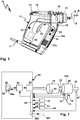
- a hand-held machine tool 10 has a housing 11, in the interior of which a drive train 20 is arranged.
- the hand machine tool 10 is, for example, a screwdriver, drill or both.
- the housing 11 can be comfortably gripped by an operator on a grip section 12.
- the drive train 20 is accommodated in an upper housing section 13, which runs like an pistol at an angle to the grip section 12.
- a front housing section 14 extends in front of the handle section 12, which can be gripped with one hand, for example, the handle section 12 and the housing section 14 being connected to one another by a lower housing section.
- a connection for a power cable 17 is located on this lower housing section, for example. Furthermore, it is possible to provide a rechargeable battery or another mobile energy storage device on this housing section or, as shown in the exemplary embodiment, in the region of the front housing section 14.
- a hand-held machine tool according to the invention it is possible for a hand-held machine tool according to the invention to be network-connected, that is to say, for example, to be connectable to an electrical supply network or to be a cordless machine, that is to say a mobile device.
- a switch 15 is provided on the handle section 12, with which a drive motor 16 of the hand machine tool 10 can be switched on or off. Furthermore, it is conceivable to use the switch 12 to set a speed of the hand machine tool 10.
- the tool 19 is, for example, a drill, a screwdriver bit or the like.
- another tool is of course expedient, for example a polishing tool, grinding tool or milling tool or the like.
- the drive motor 16 drives the tool holder 18 via a gear 30.
- a striking mechanism 21 can be connected between the transmission 30 and the tool holder 18, so that even a striking operation, for example for drilling holes, is possible with the hand machine tool 10.
- the drive motor 16 drives the transmission 30 using its motor shaft 22.
- the transmission 30 has a gear stage 31 with switchable first and second gear stages 41 and 42.
- the switching stage 31 is followed by a transmission stage 32 which, for example, further reduces an output speed of the switching stage 31.
- the translation stage 32 can be, for example, a reduction stage.
- the gear 30 is designed, for example, as a planetary gear.
- the transmission 30 can be driven via a drive shaft, for example the motor shaft 22.
- a drive wheel 33 is arranged on the motor shaft 22.
- the drive wheel 33 drives the switching stage 31.
- the drive wheel 33 forms a gear drive 25.
- the drive gear 33 is a sun gear 34 that drives transmission gears 35.
- the transmission gears 35 are, for example, planet gears 36 which are rotatably mounted on a planet carrier 37 on planet axes 40.
- the planet axes 40 are rotatably mounted on the planet carrier 37 or the planet gears 36 on the planet axes 40, for example.
- plain bearings, ball bearings or needle bearings or other roller bearings can be provided between the planet gears 36 and the planet axes 40 or the planet axes 40 and the planet carrier 37.
- the planet gears 36 mesh with the drive gear 33 with a first pitch circle diameter 38.
- a further, second pitch circle diameter 39 of the planet gears 36 is smaller than the pitch circle diameter 38, which contributes to a gear ratio.
- the planet gears 36 mesh with a ring gear 45 and a sun gear 46.
- the ring gear 45 is arranged radially on the outside with respect to the planet gears 36 and surrounds them in an annular manner.
- the sun gear 46 is provided, so to speak, in the center of the planet gears 36.
- the ring gear 45 is assigned to the first gear stage 41 and the sun gear 46 to the second gear stage 42.
- the ring gear 45 forms a locking gear element 43, the sun gear 46 a locking gear element 44.
- a respective locking gear element 43 or 44 is locked by locking devices 61 or 62 of a shift arrangement 60, it forms a support element for the transmission gears 35, in the present case the planet gears 36.
- the locking gear element 43 or 44 which is locked in each case, so to speak, switches the respective first and second gear stages 41, 42 active.
- a locking gear element 43, 44 is not locked by the associated locking device 61, 62, it can rotate freely so that it does not provide any support for the transmission wheels 35.
- An unlocked locking gear element 43, 44 switches the assigned first and second gear stage 41, 42 to inactive. Active and inactive should be understood that torque can be transmitted from the drive side to the output side.
- the locking gear element 43 is arranged with its radially outer circumference, so to speak, directly on or next to the locking device 61. This is not possible with the sun wheel 46, which is arranged centrally on the inside, so to speak. However, this also has a radially outer support region, namely in the form of a support wheel 47 which is connected to the sun wheel 46 or is in one piece. For example, the support gear 47 is connected to the sun gear 46 by a connecting washer and / or spokes 47A.
- the support wheel 46 and the locking gear element 43, ie the ring gear 45, have the same radial outer circumferences.
- a passage opening 48 is provided in the sun gear 46 or the locking gear element 44, through which the motor shaft 22 is connected to the drive gear 33.
- the switching stage 31 drives the transmission stage 32 via an output gear 49.
- the translation stage 32 is designed as a planetary stage 50.
- the driven wheel 49 is driven by the planet carrier 37 or in one piece with it.
- the driven wheel 49 projects in front of the planet carrier 37.
- the driven gear 49 mesh planet gears 51 which are rotatably supported on a planet carrier 52 by means of planetary axes 53.
- the driven gear 49 forms a sun gear for the planet gears 51.
- the planet gears 51 are rotatably mounted on the planet axes 53, for example.
- the cover 95 has a passage opening for the motor shaft 22 or another drive shaft.
- the gear 30 can advantageously be encapsulated, can have seals or the like, for example at an opening on the front 92, where the output shaft 55 penetrates the gear housing 90.
- the planet gears 36 and thus the transmission wheels 35 are not supported on the locking gear element 43 with respect to the gear housing 90, but can rotate freely.
- the gear stage 41 is thus inactive.
- the other gear stage 42 is then active, namely that its locking gear element 44 is supported by the locking device 62 with respect to the housing 90, so that the planet gears 36 can roll on the outer circumference of the sun gear 46 and thereby the power flow or the torque transmission from the gear drive 25 to Transmission output 26 extends over the gear stage 42.
- the locking device 62 releases the locking gear element 44, so that no power flow via the second gear stage 44 is possible.
- the sun gear 46 rotates freely.
- the other locking device 61 is then active, i.e. it locks the support element or locking gear element 43 assigned to it, namely the ring gear 45.
- the transmission gears 35 in this case the planet gears 36, can roll on the ring gear 45 which is stationary with respect to the gear housing 90 and thus a power flow or torque transmission from the gear drive 25 to Enable gearbox output 26.
- the gear stages 41, 42 each provide a torque ratio and speed change between the gear drive 25 on the one hand and the gear output 26 on the other hand. By simply reversing the direction of rotation of the drive motor 16, a different speed of the tool holder 18 and / or a different torque output on the tool holder 18 can be realized.
- the controller 80 changes the direction of rotation of the drive motor 16, for example, so that the transmission 30 shifts back from the second transmission stage to the first transmission stage, for example. However, if a speed of the drive motor 16 exceeds a predetermined amount, the controller 80 reverses the direction of rotation of the drive motor 16 so that the transmission 30 shifts from the first gear stage to the second gear stage so that the drive motor 16 can rotate at a lower speed.
- the locking devices 61, 62 are, so to speak, supported in a sandwich-like manner between the locking gear elements 43 and 44 on the one hand and a housing section 94 of the gear housing 90.
- the locking devices 61, 62 form, so to speak, radially outer components of the transmission 30. Because the locking devices 61, 62 are arranged radially on the outside, they are also easily accessible for interventions from the outside, for example for changing over the respective blocking direction.
- the two locking devices 61, 62 which are switched off as freewheels, can be switched with respect to their locking direction and freewheeling direction.
- the locking devices 61, 62 comprise a common support ring 63, which could be called a freewheel ring.
- each locking device 61, 62 it would also be possible for each locking device 61, 62 to be designed as a separate freewheel device, i.e. that there are no common components.
- the support ring 63 is fixed in relation to the gear housing 90.
- support bodies 64 in particular bolts or the like, are positively inserted between the inner circumference of the gear housing 90, that is to say the housing section 94, and the outer circumference of the support ring 63 and hold the two components to one another in a form-fitting manner.
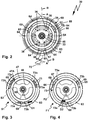
- the support ring 63 On its inner circumference, the support ring 63 has a plurality of, for example three, freewheel recesses 65 offset in terms of the angle of rotation, in each of which a locking element 68 or 69, in particular a roller or a pin, of a respective locking device 61 is guided under 62.
- the locking devices 61 have locking elements 68, 69 which are separate from one another, so that they can have opposite freewheeling directions in and locking directions.
- the locking elements 68, 69 are mounted between the outer circumferences of the locking gear elements 43, 44 and the inner circumference of the support ring 63 in the region of the respective freewheel recesses 65.
- the locking elements 68, 69 with respect to an axis of rotation D about which the locking gear elements 45, 46, namely the ring gear 45 and the combination of sun gear 46 and support gear 47 are rotated, are moved on the outer circumference of the respective locking gear element 43, 44, namely into or out of the area of the freewheel recesses 65, in clamping bevels or constrictions 66, 67.
- the respective locking device 61 or 62 is in the freewheel. However, if the locking elements 68, 69 are moved in the direction of the clamping slope or constrictions 66 or 67, the locking device 61, 62 is locked. The associated locking gear element 43, 44 is then blocked by the locking elements 68, 69 arranged on its outer circumference, which are located in one of the clamping bevels 66 or 67 and are supported on the support ring 63, with respect to rotatability about the axis of rotation D, so that the locking gear element 43, 44 can serve to support the planet gears 36 and thus the respective gear stage 41 or 42 is active.
- the blocking direction or freewheeling direction of a respective blocking device 61, 62 can be switched.
- a switching device 70 is provided which can be conveniently operated by an operator using a single, manual actuating element 71.
- the actuating element 71 is designed, for example, as a projection in front of a switching element 72, for example in the form of a ring, which can be rotated about the axis of rotation D.
- Pin-like guide elements 73 which are also referred to below as 73a and 73b, project from the switching element 72 in the direction of the blocking elements 68, 69, a respective blocking element 68, 69 being arranged between guide elements 73 which are opposite one another in pairs.
- the locking elements 69 are adjusted in the direction of the clamping slopes 66, so that the locking device 61 locks or blocks the support element or locking gear element 44 in a direction of rotation D1.
- the guide elements 73b hold the blocking elements 69 in the freewheel cutouts 65.
- the direction of rotation D2 therefore corresponds a freewheeling direction F1, the direction of rotation D1 a blocking direction S1 of the blocking device 62 in the position according to Figures 3 or 4 .
- a spring element 75 is provided in each case between the guide elements 73 and the locking elements 68, 69.
- the spring elements 75 load the locking elements 68, 69 in the direction of the locking position, i.e. in the direction of the clamping bevels 66, 67. So when the transmission 30 starts, so to speak, the locking elements 68, 69 are already loaded in the direction of the locking position, so that the locking function or as a support function of the locking gear elements 43, 44 is available as immediately as possible.
- the locking elements 68, 69 are expediently movably mounted, decoupled from one another.
- a decoupling ring 74 is arranged between the locking elements 68, 69 with respect to the axes of rotation D.
- the locking direction and the freewheeling direction of the locking devices 61, 62 can be switched in opposite directions, namely by the switching device 70.
- the actuating element 71 is actuated about the axis of rotation D
- the guide elements 73 also make this rotary movement, so that they proceed approximately from a central position Figure 2 are adjustable in this respect with respect to the axis of rotation D offset, for example a position for clockwise rotation or a position for counterclockwise rotation of the tool holder 18.
- the blocking direction S1 and the freewheeling direction F1 can be switched in opposite directions.
- the switching element 72 is created counterclockwise, so that the guide elements 73 are shown in broken lines in FIG Figure 3 and Figure 4 Assume the position shown, the guide elements 73a hold the blocking elements 69 in the freewheeling position, which, however, then corresponds to the direction of rotation D1.
- the locking gear element 44 can then rotate freely in the direction of rotation D1, in the opposite direction, in the direction of rotation D1, however, it is prevented from rotating by the locking device 62, that is, locked.
- Figure 3 is shown in dashed lines one of the locking elements 69 in a locking position, in which is applied to the clamping slope 67, which is a locking direction S2 corresponds.
- the position of the guide elements 73a according to Figure 4 in dashed lines corresponds to a freewheeling position Figure 2 .
- the controller 80 adjusts the direction of rotation of the drive motor 16 depending on the position of the switching device 70 for clockwise or counterclockwise rotation, so that it switches after switching from clockwise rotation to counterclockwise rotation or vice versa in the gear stage assumed before the direction of rotation was switched 41 or 42 starts up.
- a sensor 85 is arranged on the switching device 70 in order to detect its respective switching position.
- the sensor 85 is, for example, an electrical contact, a contactless contact or the like.
- an inductive, optical or capacitive measuring element can be provided as a sensor, but also an electrical contact switch or the like.
- the first gear stage 41 represents a minus gear
- the second gear stage 42 a positive gear, so that the gear stages 41 and 42 can be switched by a simple reversal of the direction of rotation of the drive motor 16 in the transmission 30, but no reversal of the direction of rotation is connected to the transmission output 26.
- This concept can also be used for types of gears that are not designed as planetary gears Figures 8 and 9 still becomes clear.
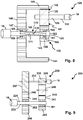
- a drive train 120 ( Figure 8 ) drives the drive motor 16, for example via a motor shaft 122, which also represents a gear drive 125, a first gear stage 141 and a second gear stage 142 of a gear 130.
- Both switching stages 141 and 142 cause a change in speed and torque between the gear drive 125 on the one hand and the gear output 126 on the other, on which the tool holder 18 can be arranged directly, for example.
- a further gear stage is arranged on the gear output 126 or that this gear output 126 is arranged on a gear stage, not shown, for example a reduction stage.
- Locking devices 161, 162 are arranged on the motor shaft 122, which in the area of the transmission 120 could easily also be referred to as a transmission shaft. In the simplest case, these could be freewheels, but also switchable locking devices whose locking direction and release direction of rotation or freewheeling direction can be switched, for example by an electrical actuator that can be controlled by the controller 80.
- the locking devices 161 and 162 are provided between locking gear elements 143 and 144. If a respective locking device 161 or 162 is locked, it takes its assigned locking gear element 143, 144. In an opposite direction of rotation, however, locking gear element 143 or 144 can be rotated on locking device 161 or 162, that is, it is not blocked or locked.
- the locking gear element 143 is, for example, a gearwheel or drive wheel 146 which meshes with a transmission wheel 135.
- the transmission wheel 135 is rotatably connected to an output shaft 155 which has the tool holder 18 at its free end or drives it via a gear, not shown.
- the gear stage 141 represents a so-called minus gear.
- the locking gear element 144 is, for example, a ring gear 145 , with the inner circumference of the transmission wheel 135 meshes. A positive transmission is thus realized.
- the ring gear 145 has radially inward spokes 146 or other connecting elements which are connected to the locking device 162 or have a radially inner support wheel 147 which can be locked by the locking device 162.
- the transmission 130 is also very compact, because both locking gear elements 143, 144 act directly on one and the same drive wheel 135.
- a switching device 170 is shown as an example of a manual or electrically actuated switching device for switching the blocking directions or free-running direction in the blocking devices 161 and 161.
- Their actuating element 171 acts, for example, on blocking elements 168 and 169 of the blocking devices 161, 162 similarly to the guide elements 73 of the switching device 70.
- the switching device 171 must switch in opposite directions, since the blocking gear elements 143, 144 must have an opposite freewheeling direction, so that gear stage 141 and the other time, gear stage 142 is inactive.
- One possibility for such an actuation is e.g. in that the actuating element 171 is rotatably mounted about an axis of rotation 176 so that it can act in opposite directions on the locking elements 168, 169.
- a gear 230 is provided, which is also designed so that there is no reversal of the direction of rotation between its gear drive 225 and its gear output 226 when the drive motor 16 rotates in opposite directions.
- locking devices 261, 262, which are assigned to gear stages 241 and 242 are arranged coaxially and next to one another on a motor shaft 222, which can also represent a transmission shaft.
- the locking devices 261 and 262 carry locking gear elements 243, 244 on their outer circumference, of which, when the motor shaft 222 is rotated in one direction of rotation, a locking gear element 243 is taken along, the other locking gear element 244 rotates freely, while in the opposite direction of rotation the locking gear element 243 is freely rotatable is while the ratchet element 244 is driven by the motor shaft 222.
- the locking gear elements 243, 244 are, for example, gears.
- the locking gear elements 243, 244 are designed, for example, as drive wheels 245, 246.
- the drive wheel 245 drives a transmission wheel 235 via a transmission wheel 248, which is provided for driving the tool holder 18.
- the transmission wheel 235 is arranged in a rotationally fixed manner on an output shaft 255.
- the tool holder 18 is provided directly on the output shaft 255.
- the output shaft 255 could, however, also be configured to drive a further gear stage and / or an impact mechanism.
- Another transmission wheel 247 is also non-rotatably connected to the output shaft 255 and serves to drive it.
- a first gear stage 241 is active, which altogether implements a so-called positive gear.
- the transmission wheel 248 realizes with the blocking gear element 243 and the drive wheel 235 a minus gear, so that a plus gear is present overall.
- the second gear stage 242 is designed as a minus gear. In any case, the direction of rotation of the transmission output 226 is always the same in the case of opposite directions of rotation of the transmission drive 225.
- a powertrain 320 according to Figures 10 and 11 comprises a transmission 330, which is constructed similarly to the transmission 30 or its switching stage 31 with respect to a switching stage 331, but the actuation concept (with a switching device 370) is different for a switching arrangement 360, which corresponds functionally to the switching arrangement 60, and the Output side of the transmission 330, where instead of a simple planetary stage or a simple reduction gear as in the embodiment according to Figures 5 and 6 a switchable transmission arrangement 350 is provided.
- the same or similar components in the embodiment according to Figures 5 and 6 as well as the other embodiment Figures 10 and 11 are present, they are provided with the same reference numbers, but in order to clarify differences, in some cases with 300 increased reference numbers.
- the gear stage 331 drives a gear stage 332 with its gear output 25, which can, but does not have to, work as a reduction stage in the sense of a speed reduction.
- the drive motor 16 drives a drive wheel 333 via the motor shaft 22.
- the drive gear 333 forms a sun gear 334, which meshes with planet gears 336.
- the planet gears 336 advantageously form transmission gears 35.
- the planet gears 336 are rotatably mounted on a planet carrier 337.
- planetary axes 40 are rotatably supported on planet carrier 37, or planetary carriers 336 are rotatably supported on planetary axes 40.
- the planet gears 336 have different pitch circle diameters 38, 39 like the planet gears 36. With the pitch circle diameter 38, the planet gears 336 mesh with the sun gear 334, while the smaller pitch circle diameter 39 provides that the planet gears 336 come into engagement with a ring gear 345, that is, with it can comb or take the ring gear 345 with it.
- the gear stage 331 has a first gear stage 341 (corresponding to the gear stage 41) and a second gear stage 342 (corresponding to the gear stage 42), between which the gear stage 331 can be switched by reversing the direction of rotation of the drive motor 16.
- the planet gears 336 are also supported, so to speak, radially on the inside, namely can roll on a sun gear 346, which forms part of a locking gear element 344.
- the locking gear element 344 corresponds to the locking gear element 44 and has a passage opening 48 for the motor shaft 22.
- the switching arrangement 360 comprises a locking device 361 for locking or unlocking the locking gear element 343 and a locking device 362 for locking or unlocking the locking gear element 344.
- locking elements 368, 369 are supported on a support ring or freewheel ring 363 (similar to components 68, 69 and 63) and are preferably by in Figure 10 visible spring elements 375 (corresponding to the spring elements 75).
- the actuating element 371 projects radially outward in front of a gearbox housing 390 of the gearbox 330 and can therefore be gripped comfortably by the operator.
- the actuating element 371 is preferably rotatably mounted on the support ring or freewheel ring 363 or extends through it.
- the actuating element 371 is provided on a housing section 394 of the transmission housing 390, in which the switching stage 331 is accommodated.
- the actuating element 371 is rotatably connected to the switching element 372.
- a section 374 of the rod-shaped or ring-shaped actuating element 371, for example, is coupled to the switching element 372.
- the switching element 372 is ring-shaped, for example, similar to the switching element 72.
- the shift element 372 is, however, arranged between the gear stages 341, 342 and between the locking gear elements 343, 344.
- a projection 372a engages in an intermediate section between the ring gear 345 and the support wheel 347 of the locking gear element 344.
- the transmission 390 is also closed on its side facing the drive motor 16 by a cover, here a cover 395.
- a cover 395 On a side facing away from the cover 395, next to the housing section 394, there is a further housing section 393 which receives the gear arrangement 350, that is to say the gear stage 332.
- the housing section 393 is closed by a cover 391, on the front or front side 392 of which the output shaft 55 is coupled to the tool holder 18.
- the tool shaft 18 is driven by the gear stage or switching stage 332, which in turn is coupled to the gear output 26 of the switching stage 31.
- the transmission output 26 comprises an output gear 349, which is, for example, firmly connected to the planet carrier 337, for example in one piece with it.
- the driven gear 349 forms a sun gear with which planet gears 351 of the gear arrangement 350 mesh.
- the planet gears 351 are rotatable with respect to a planet carrier 352, for example by being rotatably mounted on planetary axes 353 or by the planetary axes 353 being rotatably supported on planetary carrier 352.
- Shown switching position of the gear arrangement 350 couples a ratchet wheel 354, for example a ring gear, the gear arrangement 350 connects the planet gears 351 to the planet carrier 337 in a rotationally fixed manner.
- the planet carrier 337 has, for example on its outer circumference, a toothing 337a which can engage with an internal toothing of the switching wheel 354.
- a respective planet gear 351 is also in engagement with this toothing or a toothing lying next to it.
- the planet gears 351 mesh with the internal toothing of the ratchet wheel 354, so they roll on this.
- the ratchet wheel 354 in turn is fixed in a rotationally fixed manner with respect to the transmission housing, for example by means of an external toothing 354a of the ratchet wheel 354 which engages with an internal toothing 354b on the housing 390, for example the cover 391.
- the internal toothing 354b is radially on the inside
- the external toothing 354a is radially on the outside.
- a switching position can accordingly Figure 10 can be set, in which the output shaft 55 and thus the tool on the tool holder 18 rotates at the speed of the planet carrier 337 or the transmission output 26, and a switching position accordingly Figure 11 in which a reduction stage is implemented.
- the sun gear or drive gear 349 drives the planet gears 351, which in turn roll on the ring gear or gear wheel 354, thus reducing the speed and simultaneously increasing the torque on the output.
- the switchable transmission arrangement 350 can be switched manually, for example by an actuating element 310, which is displaceably mounted in a receptacle 311 of the transmission housing 390.
- the actuating element 310 is coupled in motion by means of a coupling element 312 to the ratchet wheel 354, but could also be arranged fixedly on the ratchet wheel 354.
- the coupling element 312 comprises, for example, pins, brackets or the like other components which enable a power transmission from an outside of the gear housing 390 into its interior, where the switching wheel 354 is arranged.
- the receptacle 311 forms a sliding bearing or a sliding receptacle in which the actuating element 310 is accommodated in a linearly displaceable manner.
- the actuating element 310 is motion-coupled or in one piece with a manually graspable actuating handle 313, for example a ring or slide.
- the actuating handle 313 projects, for example, in front of the housing 11 of the hand machine tool 10, and is therefore easy to grasp.
- An alternative or supplementary drive concept or actuation concept for the switching wheel 354, and consequently a concept for switching the transmission arrangement 350 is represented by an actuator 387, for example an electromagnet, an electric motor or the like (a pneumatic drive is also possible).
- the actuator 387 is designed and provided to adjust the ratchet wheel 354, that is to say a shift element of the transmission arrangement 350, between at least two shift positions.
- actuator 387 can switch wheel 354 between the switch positions according to FIG Figures 10 and 11 adjust back and forth.
- the actuator 387 is controlled, for example, via an electrical switch 24a on the housing 11 of the hand machine tool 10.
- the actuator 387 is accommodated in a protected manner in the interior of the transmission housing 390.
- the representation of the actuator 387 is to be understood as an example.
- the controller 80 is preferably designed to control the actuator 387. For example, it has a switching output 388 for switching the actuator 387. In Figure 7 is that indicated.
- the controller 80 can thus, for example, automatically shift the transmission stage or shift stage 331, advantageously also the shiftable transmission arrangement 350 or the shift stage 332.
- a four-speed transmission can thus be implemented overall, which is even fully automatic works.
- sensors that interact with the controller 80 can also be provided at the output area.
- a sensor 87 for detecting the speed and / or torque and / or direction of rotation or the like for example a tachometer, a torque detection, can be provided on the tool shaft or output shaft 55.
- a sensor 88 for example an optical sensor, a Hall sensor or the like, can detect, for example, its torque and / or direction of rotation and / or speed in the drive motor 16.
- a sensor 89 in particular for speed detection and / or torque detection and / or rotation direction detection, can also be provided at the input of the transmission 30, 330, for example on the motor shaft 22.
- the sensors 87, 88, 89 report their respective sensor signals via the input interface 84 to the controller 80, which uses the software program 86, for example, to set the speed and / or direction of rotation of the drive motor 16 in order to shift the transmission 30, 330 in this way.
- the controller 80 can control the actuator 387.
- the sensor signals of the sensors 87, 89, 88 can also be used to regulate and / or control the drive motor 16 and in particular also to shift the transmission 330, in particular its gear stage 332.
- an operator can, for example, specify a desired maximum speed or target speed SD of the output shaft 55.
- a desired maximum speed or target speed SD of the output shaft 55 For example, the operator can specify a maximum speed of 2000 to 4000 revolutions / min for drilling operations and a maximum speed of 500 to 2000 revolutions / min for screwing operations.
- an optionally available torque setting element 24 for example a rotatable adjusting element, a slide or the like
- the operator can, for example, specify a desired maximum torque or target torque SM on the output shaft 55.
- damage to screws or the like can be prevented, for example.
- Speed control or torque control can be advantageous, for example, in a milling machine or saw.
- a touch-sensitive display can also be provided, which displays the set values SM and / or SD.
- a control module 86a of the software program 86 can, for example, use the maximum values or target values SM and / or SD and the feedback of the set values, namely the actual values which the sensors 87, 88, 89 deliver, the drive motor 16 and / or control the output stage 83 and / or rules. Furthermore, the control module 86a can also control the actuator 387 in accordance with these values via the switching output 388 to switch the gear stage 332.
- the controller 80 controls the actuator 387 to shift the transmission stage 332 from the shift position in which the shift stage 332 does not reduce the speed relative to the transmission output 26 ( Figure 10 ), in the shift position in which gear stage 332 acts as a reduction gear ( Figure 11 ), ie the position at which the planet gears 351 roll in the ring gear 354.
- the planetary axes 353 or 53 can be components of a spindle stop, i.e. that a rotation lock on the output side of the gear 30, 330 can be easily implemented at this point.
Abstract
Die Erfindung betrifft eine Hand-Werkzeugmaschine (10), insbesondere ein Schraubgerät und/oder Bohrgerät, mit einem Antriebsmotor (16) zum Antreiben eines Getriebe-Antriebs (25) eines Getriebes (30), das einen Getriebe-Abtrieb (26) zum Antreiben einer Werkzeugaufnahme (18) der Hand-Werkzeugmaschine (10) und eine erste Getriebestufe (41) und eine zweite Getriebestufe (42) aufweist, wobei das Getriebe eine erste Sperreinrichtung (61) zum Sperren eines ein Sperrgetriebeelement (43) bildenden Getriebeelements der ersten Getriebestufe (41) und eine zweite Sperreinrichtung (62) zum Sperren eines ein Sperrgetriebeelement bildenden Getriebeelements der zweiten Getriebestufe (42) aufweist, wobei die Getriebestufe mit dem jeweils gesperrten Sperrgetriebeelement ein Drehmoment vom Getriebe-Antrieb (25) zum Getriebe-Abtrieb (26) überträgt, wobei eine Drehrichtung des Antriebsmotors (16) umschaltbar ist und in Abhängigkeit von der Drehrichtung des Antriebsmotors (16) die erste Getriebestufe (41) oder die zweite Getriebestufe (42) ein Drehmoment vom Getriebe-Antrieb (25) zum Getriebe-Abtrieb (26) überträgt. Es ist vorgesehen, dass eine der beiden Getriebestufen eine Drehrichtungsumkehr zwischen dem Getriebe-Antrieb (25) und dem Getriebe-Abtrieb (26) bewirkt.The invention relates to a hand machine tool (10), in particular a screwing device and / or drilling device, with a drive motor (16) for driving a gear drive (25) of a gear (30), which drives a gear drive (26) has a tool holder (18) of the hand machine tool (10) and a first gear stage (41) and a second gear stage (42), the gear having a first locking device (61) for locking a gear element of the first gear stage forming a locking gear element (43) (41) and a second locking device (62) for locking a gear element forming a locking gear element of the second gear stage (42), wherein the gear stage with the locked locking gear element transmits torque from the gear drive (25) to the gear output (26) , wherein a direction of rotation of the drive motor (16) is switchable and, depending on the direction of rotation of the drive motor (16) or the first gear stage (41) he transmits the second gear stage (42) a torque from the gear drive (25) to the gear output (26). It is provided that one of the two gear stages causes a reversal of the direction of rotation between the gear drive (25) and the gear output (26).
Description
Die Erfindung betrifft eine Hand-Werkzeugmaschine, insbesondere ein Schraubgerät und/oder Bohrgerät, mit einem Antriebsmotor zum Antreiben eines Getriebe-Antriebs eines Getriebes, das einen Getriebe-Abtrieb zum Antreiben einer Werkzeugaufnahme der Hand-Werkzeugmaschine und eine erste Getriebestufe und eine zweite Getriebestufe aufweist, wobei das Getriebe eine erste Sperreinrichtung zum Sperren eines ein Sperrgetriebeelement bildenden Getriebeelements der ersten Getriebestufe und eine zweite Sperreinrichtung zum Sperren eines ein Sperrgetriebeelement bildenden Getriebeelements der zweiten Getriebestufe aufweist, wobei die Getriebestufe mit dem jeweils gesperrten Sperrgetriebeelement ein Drehmoment vom Getriebe-Antrieb zum Getriebe-Abtrieb überträgt, wobei eine Drehrichtung des Antriebsmotors umschaltbar ist und in Abhängigkeit von der Drehrichtung des Antriebsmotors die erste Getriebestufe oder die zweite Getriebestufe ein Drehmoment vom Getriebe-Antrieb zum Getriebe-Abtrieb überträgt.The invention relates to a hand-held machine tool, in particular a screwing device and / or drilling device, with a drive motor for driving a gear drive of a transmission, which has a gear output for driving a tool holder of the hand-held machine tool and a first gear stage and a second gear stage , wherein the transmission has a first locking device for locking a gear element forming a locking gear element of the first gear stage and a second locking device for locking a gear element forming a locking gear element of the second gear stage, the gear stage with the respectively locked locking gear element having a torque from the gear drive to the gear Output transmits, wherein a direction of rotation of the drive motor is switchable and, depending on the direction of rotation of the drive motor, the first gear stage or the second gear stage transmits torque from the gear drive to the gear output.
Eine Hand-Werkzeugmaschine dieser Art in Gestalt eines Schraubers ist beispielsweise in
Es ist daher die Aufgabe der vorliegenden Erfindung, eine verbesserte Hand-Werkzeugmaschine mit einem Getriebe bereitzustellen.It is therefore the object of the present invention to provide an improved hand machine tool with a gear.
Zur Lösung der Aufgabe ist bei einer Hand-Werkzeugmaschine der eingangs genannten Art vorgesehen, dass beide Getriebestufen eine Drehzahlveränderung zwischen Getriebe-Antrieb und Getriebe-Abtrieb bewirken und eine der beiden Getriebestufen eine Drehrichtungsumkehr zwischen dem Getriebe-Antrieb und dem Getriebe-Abtrieb bewirkt.To solve the problem, it is provided in a hand machine tool of the type mentioned at the outset that both gear stages change the speed cause between gear drive and gear output and one of the two gear stages reverses the direction of rotation between the gear drive and the gear output.
Dadurch wird beispielsweise bewirkt, dass bei einer Drehrichtungsumkehr am Getriebe-Antrieb der Getriebe-Abtrieb keine Drehrichtungsumkehr aufweist.This has the effect, for example, that when the direction of rotation is reversed on the transmission drive, the transmission output has no reversal of the direction of rotation.
Das Getriebe sorgt also dafür, dass trotz des Schaltens von der einen Getriebestufe in die andere Getriebestufe der Getriebe-Abtrieb stets in derselben Drehrichtung dreht, also keine Drehrichtungsumkehr auf der Seite des Abtriebs erfolgt. Es ist also zweckmäßigerweise vorgesehen, die erste Getriebestufe und die zweite Getriebestufe den Abtrieb bei einander entgegengesetzten Drehrichtungen des Antriebsmotors in derselben Drehrichtung antreiben.The gearbox thus ensures that, despite shifting from one gear stage to the other gear stage, the gear output always rotates in the same direction of rotation, ie there is no reversal of the direction of rotation on the output side. It is therefore expediently provided that the first gear stage and the second gear stage drive the output in opposite directions of rotation of the drive motor in the same direction of rotation.
Bei der ersten Getriebestufe kann es sich beispielsweise um ein sogenanntes Plusgetriebe handeln, bei der zweiten Getriebestufe um ein sogenanntes Minusgetriebe. Ein Minusgetriebe bewirkt beispielsweise eine Drehrichtungsumkehr von seiner Antriebsseite zu seiner Abtriebseite hin, ein Plusgetriebe behält die Drehrichtung bei.The first gear stage can be, for example, a so-called positive gear, and the second gear stage can be a so-called minus gear. A minus gear, for example, reverses the direction of rotation from its drive side to its output side, a plus gear maintains the direction of rotation.
Somit kann beispielsweise eine Schraube mit stets derselben Drehrichtung in ein Werkstück eingedreht werden, obwohl das Getriebe schaltet. In beiden Getriebestufen findet jedoch eine Veränderung von Drehmoment und Drehzahl zwischen der Antriebsseite und der Abtriebseite statt, das heißt dass beispielsweise eine hohe Drehzahl des Antriebsmotors in eine vergleichsweise niedrige Drehzahl am Getriebe-Abtrieb in jeder der Getriebestufen umgesetzt werden kann.This means, for example, that a screw can always be screwed into a workpiece with the same direction of rotation, even though the gearbox shifts. In both gear stages, however, there is a change in torque and speed between the drive side and the output side, which means that, for example, a high speed of the drive motor can be converted into a comparatively low speed at the gear output in each of the gear stages.
Die erste Getriebestufe weist zweckmäßigerweise ein erstes Übersetzungsverhältnis und die zweite Getriebestufe ein zweites Übersetzungsverhältnis, das sich vom ersten Übersetzungsverhältnis unterscheidet, zwischen Antrieb und Abtrieb auf. Bei der ersten Getriebestufe und der zweiten Getriebestufe ist jeweils eine Drehzahlveränderung zwischen Antrieb und Abtrieb des Getriebes vorhanden. Der Abtrieb und der Antrieb sind also nicht unmittelbar mit gleicher Drehzahl gekoppelt.The first gear stage expediently has a first gear ratio and the second gear stage has a second gear ratio, which differs from the first gear ratio, between the drive and the output. The first gear stage and the second gear stage each have a speed change between the input and output of the gear. Of the Output and drive are therefore not directly coupled at the same speed.
Unter einer Getriebestufe soll also vorteilhaft verstanden werden, dass in der Getriebestufe ein Drehmoment und eine Drehzahl zwischen Antriebsseite und Abtriebseite der Getriebestufe verändert werden.A gear stage should therefore advantageously be understood to mean that in the gear stage a torque and a speed are changed between the drive side and the output side of the gear stage.
Bevorzugt handelt es sich bei dem Getriebe um ein Zahngetriebe, wobei auch eine zumindest teilweise Ausgestaltung als ein Reibrad-Getriebe oder Rollengetriebe möglich ist.The gear is preferably a toothed gear, and an at least partial configuration as a friction wheel gear or roller gear is also possible.
Das Getriebe umfasst vorzugsweise ein Planetengetriebe oder ein Umlaufrädergetriebe oder ist als ein Planetengetriebe oder ein Umlaufrädergetriebe ausgestaltet. Die erste Getriebestufe und die zweite Getriebestufe bilden zweckmäßigerweise Bestandteile eines Planetengetriebes oder Umlaufrädergetriebes.The transmission preferably comprises a planetary gear or an epicyclic gear or is designed as a planetary gear or an epicyclic gear. The first gear stage and the second gear stage expediently form components of a planetary gear or epicyclic gear.
Bemerkt sei, dass die erste Getriebestufe und die zweite Getriebestufe zum Beispiel Bestandteile eines Planetengetriebes bilden können, während eine vorgeschaltete oder nachgeschaltete weitere Getriebestufe, insbesondere eine Nicht-schaltbare oder Nicht-geschaltete Getriebestufe, zwar ebenfalls als gleichartiges Getriebe, beispielsweise Planetengetriebe, ausgestaltet sein können. Es ist aber auch möglich, dass diese weitere Getriebestufe einen anderen Getriebetyp aufweist, beispielsweise ein Zahnradgetriebe, bei dem Antrieb und Abtrieb nicht koaxial sind.It should be noted that the first gear stage and the second gear stage can form components of a planetary gear, for example, while an upstream or downstream further gear stage, in particular a non-shiftable or non-shifted gear stage, can also be designed as a similar gear, for example planetary gear . However, it is also possible for this further gear stage to have a different type of gear, for example a gearwheel gear, in which the input and output are not coaxial.
Eine bevorzugte Ausführungsform der Erfindung sieht vor, dass das Getriebe oder die Hand-Werkzeugmaschine als Ganzes mindestens ein Getrieberad aufweist, das mit beiden durch die erste Sperreinrichtung und die zweite Sperreinrichtung sperrbaren Sperrgetriebeelementen kämmt. Diese Bauform ist besonders kompakt. Die Sperrgetriebeelemente können beispielsweise das Getrieberad sozusagen aktiv antreiben, sodass dieses ein Drehmoment auf den Getriebe-Abtrieb übertragen kann. Es ist aber auch möglich, dass die Sperrgetriebeelemente eine Abstützung für das Getrieberad bilden oder das Getrieberad abstützen, so dass das Getrieberad an jeweiligen Sperrgetriebeelement abwälzen kann, wenn es seine Sperrstellung einnimmt. Dies ist beispielsweise bei einem Planetengetriebe besonders einfach realisierbar.A preferred embodiment of the invention provides that the gear or the hand machine tool as a whole has at least one gear wheel which meshes with both locking gear elements which can be locked by the first locking device and the second locking device. This design is particularly compact. The locking gear elements can, for example, actively drive the gear wheel, so to speak, so that it can transmit a torque to the gear output. But it is also possible that the locking gear elements form a support for the gear wheel or support the gear wheel, so that the gear wheel can roll on the respective locking gear element when it assumes its locking position. This is particularly easy to achieve, for example, in a planetary gear.
Eine vorteilhafte Ausgestaltung des erfindungsgemäßen Getriebes sieht vor, dass es eine Planetenstufe aufweist. Planetenräder der Planetenstufe sind an einem Planetenträger drehbar gelagert, der einen Abtrieb aufweist. Die Planetenräder sind durch ein Antriebsrad angetrieben. Das Antriebsrad ist beispielsweise unmittelbar an einer Abtriebswelle des Antriebsmotors angeordnet oder mit dieser drehverbunden. Es ist auch möglich, dass das Antriebsrad für die Planetenräder seinerseits mit einem Abtrieb eine Getriebestufe gekoppelt ist. Beispielsweise kann das Antriebsrad an einem Abtrieb einer Planetenstufe angeordnet sein. Der Abtrieb des Planetenträgers seinerseits ist beispielsweise mit dem Getriebe-Abtrieb drehverbunden, drehgekoppelt oder dergleichen. Beispielsweise kann der Abtrieb des Planetenträgers direkt mit der Werkzeugaufnahme verbunden sein und diese unmittelbar antreiben. Es ist aber auch möglich, dass der Abtrieb des Planetenträgers über mindestens eine weitere Getriebestufe, beispielsweise eine Planeten-Getriebestufe, die Werkzeugaufnahme antreibt.An advantageous embodiment of the transmission according to the invention provides that it has a planetary stage. Planetary gears of the planetary stage are rotatably mounted on a planet carrier which has an output. The planet gears are driven by a drive gear. The drive wheel is arranged, for example, directly on an output shaft of the drive motor or is rotationally connected to it. It is also possible that the drive wheel for the planet gears is in turn coupled to an output one gear stage. For example, the drive wheel can be arranged on an output of a planetary stage. The output of the planet carrier, for its part, is rotationally connected, rotationally coupled, or the like, for example, to the transmission output. For example, the output of the planet carrier can be connected directly to the tool holder and drive it directly. However, it is also possible for the output of the planet carrier to drive the tool holder via at least one further gear stage, for example a planet gear stage.
Eine besonders bevorzugte Ausführungsform der Erfindung sieht vor, dass die Planetenräder einen ersten, dem Antriebsrad zugeordneten Wälzkreisdurchmesser und einen zweiten, von dem ersten Wälzkreisdurchmesser verschiedenen Wälzkreisdurchmesser aufweisen. Dieser zweite Wälzkreisdurchmesser ist z.B. kleiner oder größer als der erste Wälzkreisdurchmesser, sodass er eine Getriebeübersetzung bewirkt. Somit können die Planetenräder bereits dazu beitragen, eine Drehzahlveränderung von der Antriebsseite zur Abtriebseite zu bewirken, insbesondere dass die erste Getriebestufe und die zweite Getriebestufe jeweils als sozusagen echte Getriebestufen ausgestaltet sind. Beispielsweise sind die Planetenräder als sogenannte Stufenplaneten oder Stufenplanetenräder ausgestaltet. Die Planetenräder können aber auch mindestens einen weiteren, zum Beispiel mindestens einen dritten, Wälzkreisdurchmesser aufweisen.A particularly preferred embodiment of the invention provides that the planet gears have a first pitch circle diameter assigned to the drive wheel and a second pitch circle diameter different from the first pitch circle diameter. This second pitch circle diameter is, for example, smaller or larger than the first pitch circle diameter, so that it effects a gear ratio. Thus, the planet gears can already contribute to causing a speed change from the drive side to the output side, in particular that the first gear stage and the second gear stage are each designed as real gear stages, so to speak. For example, the planet gears are designed as so-called stepped planets or stepped planet gears. However, the planet gears can also have at least one further, for example at least a third, pitch circle diameter.
Das Antriebsrad für die Planetenräder kann beispielsweise ein zwischen die Planetenräder eingreifendes Sonnenrad sein. Es ist auch möglich, dass das Antriebsrad für die Planetenräder ein Hohlrad ist, in welchem die Planetenräder angeordnet sind oder dass die Planetenräder aufnimmt. Das Antriebsrad ist beispielsweise, wie erwähnt, mit der Abtriebswelle des Antriebsmotors drehgekoppelt oder fest verbunden. Die Planetenräder können also von radial außen durch das Hohlrad oder von radial innen durch das Sonnenrad angetrieben werden.The drive wheel for the planet gears can be, for example, a sun gear engaging between the planet gears. It is also possible for the drive wheel for the planet gears to be a ring gear in which the planet gears are arranged or for the planet gears to be received. The drive wheel is, for example, as mentioned, rotationally coupled to the output shaft of the drive motor or fixedly connected. The planet gears can thus be driven from the radially outside by the ring gear or from the radially inside by the sun gear.
Eine vorteilhafte Ausgestaltung der Erfindung sieht vor, dass mit den Planetenrädern kämmende Getrieberäder der ersten Getriebestufe und der zweiten Getriebestufe bezüglich der Drehachse der Planetenräder zumindest teilweise ineinander eingreifen. Die Getrieberäder können beispielsweise ein Sonnenrad und ein Hohlrad umfassen, die bezüglich der Drehachse dieselbe Längsposition haben, was unten noch im Detail ausgeführt wird. An dieser Stelle sei aber bemerkt, dass selbstverständlich auch in Bezug auf die Drehachsen der Planetenräder nebeneinander angeordnete Getrieberäder mit den Planetenrädern kämmen können. Bei den Getrieberädern, die mit den Planetenrädern kämmen, handelt es sich vorzugsweise um mit den Sperreinrichtungen drehgekoppelte Getrieberäder, die durch die Sperreinrichtungen jeweils sperrbar sind. Somit können die Getrieberäder sozusagen Abstützelemente für die Planetenräder bilden.An advantageous embodiment of the invention provides that gear wheels of the first gear stage and the second gear stage meshing with the planet gears mesh at least partially with respect to the axis of rotation of the planet gears. The gearwheels can comprise, for example, a sun gear and a ring gear, which have the same longitudinal position with respect to the axis of rotation, which will be explained in detail below. At this point, however, it should be noted that, of course, gear wheels arranged next to one another can also mesh with the planet wheels with respect to the axes of rotation of the planet wheels. The gear wheels which mesh with the planet wheels are preferably gear wheels which are rotationally coupled to the locking devices and can each be locked by the locking devices. The gear wheels can thus form support elements for the planet wheels, so to speak.
Eine bevorzugte Ausführungsform der Erfindung sieht vor, dass die Planetenräder mit einem durch die erste Sperreinrichtung sperrbaren Sperr-Sonnenrad und einem durch die zweite Sperreinrichtung sperrbaren Sperr-Hohlrad kämmen, so dass durch Sperren des Sperr-Sonnenrades oder des Sperr-Hohlrads die erste oder die zweite Getriebestufe aktivierbar ist. Das Sperr-Sonnenrad ist zum Beispiel radial innen, das Sperr-Hohlrad radial außen bezüglich einer zentralen Drehachse des Getriebes.A preferred embodiment of the invention provides that the planet gears mesh with a locking sun gear lockable by the first locking device and a locking ring gear lockable by the second locking device, so that by locking the locking sun gear or the locking ring gear the first or the second gear stage can be activated. The locking sun gear is, for example, radially inside, the locking ring gear radially outside with respect to a central axis of rotation of the transmission.
Das Sperr-Sonnenrad und das Sperr-Hohlrad können in Bezug auf eine Drehachse der Planetenräder oder eine Drehachse des Getriebes oder einer Drehachse des Sperr-Sonnenrads dieselbe oder zumindest etwa dieselbe Längspositionen haben oder zumindest teilweise ineinander eingreifen. Dadurch baut das Getriebe besonders kompakt.The locking sun gear and the locking ring gear can have the same or at least approximately the same longitudinal positions with respect to an axis of rotation of the planet gears or an axis of rotation of the transmission or an axis of rotation of the locking sun gear have or at least partially interfere with each other. This makes the transmission particularly compact.
Weiterhin ist es vorteilhaft, wenn das Sperr-Sonnenrad mit einem Abstützrad gekoppelt ist oder ein Abstützrad aufweist, das bezüglich einer Drehachse des Sperr-Sonnenrads neben dem Sperr-Hohlrad angeordnet ist und/oder denselben oder etwa denselben Außenumfang wie das Sperr-Hohlrad aufweist. Somit sind das Abstützrad und das Sperr-Hohlrad beispielsweise radial außen jeweils mit der zugeordneten Sperreinrichtung verbunden oder drehgekoppelt. Eine Sperreinrichtung kann also über das Abstützrad nach radial innen bis zum Sperr-Sonnenrad sozusagen durchgreifen. Das Abstützrad und das Sperr-Sonnenrad können einstückig sein. Es ist aber auch möglich, dass das Abstützrad und das Sperr-Sonnenrad zwei Räder sind, die beispielsweise fest miteinander verbunden oder über weitere Räder, beispielsweise mindestens ein Zahnrad, insbesondere ein Planetenrad oder mehrere Planetenräder, oder dergleichen miteinander drehgekoppelt sind.It is also advantageous if the locking sun gear is coupled to a support gear or has a support gear which is arranged next to the locking ring gear with respect to an axis of rotation of the locking sun gear and / or has the same or approximately the same outer circumference as the locking ring gear. Thus, the support wheel and the locking ring gear, for example radially on the outside, are each connected or rotationally coupled to the associated locking device. A locking device can thus reach through the support wheel radially inwards to the locking sun gear, so to speak. The support wheel and the locking sun gear can be in one piece. However, it is also possible for the support wheel and the ratchet sun wheel to be two wheels which, for example, are firmly connected to one another or are rotationally coupled to one another via further wheels, for example at least one gear wheel, in particular one planet wheel or a plurality of planet wheels, or the like.
Eine weitere vorteilhafte Ausgestaltung sieht vor, dass das Sperr-Sonnenrad und das Sperr-Hohlrad bezüglich einer Drehachse des Sperr-Sonnenrads dieselbe oder etwa dieselbe Längsposition aufweisen. Beispielsweise kann eine stufenartige Anordnung getroffen sein, bei der das Sperr-Sonnenrad sozusagen vor das Abstützrad vorsteht und in einen Innenraum des Sperr-Hohlrads eingreift. Das Sperr-Sonnenrad und das Sperr-Hohlrad können bezüglich der Drehachse des Sperr-Sonnenrads exakt dieselbe Längsposition aufweisen oder auch eine etwas längsversetzte Position haben.A further advantageous embodiment provides that the locking sun gear and the locking ring gear have the same or approximately the same longitudinal position with respect to an axis of rotation of the locking sun gear. For example, a step-like arrangement can be made in which the locking sun gear protrudes, so to speak, in front of the support wheel and engages in an interior of the locking ring gear. The locking sun gear and the locking ring gear can have exactly the same longitudinal position with respect to the axis of rotation of the locking sun gear or can also have a somewhat longitudinally offset position.
Das durch die erste Sperreinrichtung sperrbare Sperrgetriebeelement der ersten Getriebestufe oder das durch die zweite Sperreinrichtung sperrbare Sperrgetriebeelement der zweiten Getriebestufe oder beide sind vorzugsweise als ein Abstützrad, insbesondere als ein Hohlrad oder Sonnenrad, ausgestaltet, an denen mindestens ein Getrieberad, insbesondere ein Planetenrad, der ersten oder der zweiten Getriebestufe abwälzt.The locking gear element of the first gear stage, which can be locked by the first locking device, or the locking gear element of the second gear stage, which can be locked by the second locking device, or both are preferably designed as a support gear, in particular as a ring gear or sun gear, on which at least one gear gear, in particular a planet gear, of the first or the second gear stage.
An dieser Stelle sei bemerkt, dass bei einer Sperreinrichtung vorteilhaft vorgesehen ist, dass sie beim einem Sperren des zugeordneten Sperrgetriebeelements einer Getriebestufe das Sperrgetriebeelement sozusagen zu einem Abstützelement oder Abstützrad macht, an welchem sich ein weiteres Getriebeelement der jeweiligen Getriebestufe abstützen bzw. abwälzen kann. Somit aktiviert die Sperreinrichtung durch das Sperren eines Sperrgetriebeelements die jeweils zugeordnete Getriebestufe. Die jeweilige Getriebestufe überträgt dann vom Getriebe-Antrieb zum Getriebe-Abtrieb ein Drehmoment. Wenn jedoch das Sperrgetriebeelement von der Sperreinrichtung freigegeben ist, läuft die diesem Sperrgetriebeelement zugeordnete Getriebestufe zweckmäßigerweise frei mit oder ist nicht bezüglich des Gehäuses des Getriebes oder der Hand-Werkzeugmaschine abgestützt, sodass sie kein Drehmoment vom Getriebe-Antrieb zum Getriebe-Abtrieb überträgt.At this point it should be noted that in the case of a locking device, it is advantageously provided that when the associated locking gear element of a gear stage is locked, it turns the locking gear element into a support element or support wheel, so to speak, on which a further gear element of the respective gear stage can be supported or shifted. The locking device thus activates the respectively assigned gear stage by locking a locking gear element. The respective gear stage then transmits torque from the gear drive to the gear output. However, if the locking gear element is released by the locking device, the gear stage assigned to this locking gear element expediently runs freely or is not supported with respect to the housing of the gear or the hand machine tool, so that it does not transmit any torque from the gear drive to the gear output.
Bevorzugt ist es, wenn mindestens ein durch eine jeweilige Sperreinrichtung sperrbares Sperrgetriebeelement als ein Hohlrad ausgestaltet ist oder ein Hohlrad aufweist. Somit ist es möglich, dass dieses Hohlrad quasi radial außen mit einer Sperreinrichtung gekoppelt oder verbunden ist, sodass diese Sperreinrichtung eine optimale Abstützung gewährleistet. Ein Drehmoment, das von dem Hohlrad auf die Sperreinrichtung einwirkt, ist vergleichsweise gering.It is preferred if at least one locking gear element that can be locked by a respective locking device is configured as a ring gear or has a ring gear. It is thus possible for this ring gear to be coupled or connected virtually radially on the outside to a locking device, so that this locking device ensures optimal support. A torque that acts on the locking device from the ring gear is comparatively low.
Nun ist es möglich, dass als Sperreinrichtung beispielsweise eine aktive Sperreinrichtung vorgesehen ist, die beispielsweise anhand eines Elektromagneten oder eines sonstigen Aktors sperrbar ist.It is now possible for an active locking device to be provided as the locking device, for example, which can be locked using an electromagnet or another actuator, for example.
In diesem Fall hat die Hand-Werkzeugmaschine vorteilhaft eine Steuerung, die zum Schalten derartiger aktiver oder mit einem Aktor versehenen Sperreinrichtungen ausgestaltet ist. Die Steuerung kann beispielsweise so ausgestaltet sein, dass sie die Sperreinrichtungen aktiv umschaltet, so dass die eine Sperreinrichtung ihr zugeordnetes Sperrgetriebeelement sperrt, während die andere Sperreinrichtung das ihr zugeordnete Sperrgetriebeelement freigibt und umgekehrt. Somit kann die Steuerung sozusagen abwechselnd die eine Getriebestufe deaktivieren und die andere Getriebestufe aktivieren.In this case, the hand machine tool advantageously has a control which is designed to switch such active locking devices or those provided with an actuator. For example, the controller can be designed such that it actively switches the locking devices so that one locking device locks its associated locking gear element, while the other locking device releases the locking gear element assigned to it and vice versa. The control system can thus alternately deactivate one gear stage and activate the other gear stage.
Eine bevorzugte Ausführungsform der Erfindung sieht jedoch vor, dass die erste Sperreinrichtung und/oder die zweite Sperreinrichtung einen Freilauf umfasst oder als Freilauf ausgestaltet ist. Ein Freilauf hat den Vorteil, dass er das mit ihm gekoppelte Sperrgetriebeelement der jeweiligen Getriebestufe in der einen Drehrichtung frei drehen lässt, in der entgegengesetzten Drehrichtung jedoch blockiert oder abstützt oder sperrt. Der Vorteil ist dabei, dass die Getriebestufen sozusagen von selbst aktiviert werden, wenn die Drehrichtung des Antriebsmotors umgeschaltet wird. Eine aktive Steuerung der Sperreinrichtungen ist nicht notwendig.A preferred embodiment of the invention, however, provides that the first locking device and / or the second locking device comprises a freewheel or is designed as a freewheel. A freewheel has the advantage that it allows the locking gear element of the respective gear stage coupled to it to rotate freely in one direction of rotation, but blocks or supports or blocks it in the opposite direction of rotation. The advantage here is that the gear stages are activated automatically, so to speak, when the direction of rotation of the drive motor is switched. Active control of the locking devices is not necessary.
Ein Freilauf hat ferner eine sich selbst verstärkende Sperrwirkung.A freewheel also has a self-reinforcing locking effect.
Bevorzugt ist es, wenn mindestens einer der Freiläufe eine radial äußerste Komponente oder radial äußere Komponente des Getriebes bildet. Es ist aber auch möglich, dass eine oder beide der Freiläufe eine radial innere Komponente des Getriebes bildet. So ist es beispielsweise möglich, dass zwischen einer Abtriebswelle des Antriebsmotors und einem jeweiligen Sperrgetriebeelement der ersten Getriebestufe oder der zweiten Getriebestufe ein Freilauf angeordnet ist.It is preferred if at least one of the freewheels forms a radially outermost component or radially outer component of the transmission. However, it is also possible for one or both of the freewheels to form a radially inner component of the transmission. For example, it is possible that a freewheel is arranged between an output shaft of the drive motor and a respective locking gear element of the first gear stage or the second gear stage.
Zweckmäßigerweise ist vorgesehen, dass die erste Sperreinrichtung einen ersten Freilauf und die zweite Sperreinrichtung einen zweiten Freilauf aufweisen, wobei die Freiläufe eine gleichsinnige Sperrrichtung und eine gleichsinnige Freigabedrehrichtung aufweisen. Dadurch können beide Freiläufe sehr bequem hinsichtlich ihrer Sperrrichtung und Freigabedrehrichtung umschaltbar sein.It is expediently provided that the first locking device has a first freewheel and the second locking device has a second freewheel, the freewheels having a locking direction in the same direction and a direction of release in the same direction. As a result, both freewheels can be switched very conveniently with regard to their blocking direction and release direction of rotation.
An dieser Stelle sei erwähnt, dass es vorteilhaft ist, wenn eine Sperrrichtung mindestens einer Sperreinrichtung, insbesondere eines Freilaufes, umschaltbar ist. Somit ist es beispielsweise möglich, dass die Sperreinrichtung oder der Freilauf in ersten Drehrichtung sperrt und in einer zweiten Drehrichtung eine Drehbewegung des sperrbaren Sperrgetriebeelements der ersten oder zweiten Getriebestufe freigibt, und diese Drehrichtungen umschaltbar sind, sodass die Sperreinrichtung oder der Freilauf nach der Umschaltung in der ersten Drehrichtung eine Drehbewegung des sperrbare Sperrgetriebeelements zulässt, in der zweiten Drehrichtung jedoch sperrt oder blockiert. Dies, also das Merkmal, dass mindestens eine Sperreinrichtung eine Hand-Werkzeugmaschine gemäß Oberbegriff des Anspruchs 1 einen in Bezug auf seine Sperrrichtung schaltbaren Freilauf aufweist, stellt im Übrigen eine an sich eigenständige Erfindung dar.At this point it should be mentioned that it is advantageous if a blocking direction of at least one blocking device, in particular a freewheel, can be switched. It is thus possible, for example, that the locking device or the freewheel locks in the first direction of rotation and releases a rotary movement of the lockable locking gear element of the first or second gear stage in a second direction of rotation, and these directions of rotation can be switched over, so that the locking device or the freewheel after the switchover in the permits a rotational movement of the lockable locking gear element in the first direction of rotation, but locks or blocks in the second direction of rotation. This is the characteristic that at least one locking device a hand-held machine tool according to the preamble of
Zweckmäßigerweise ist bei einem derartigen Freilauf vorgesehen, dass er ein durch ein Federelement in Richtung seiner Sperrstellung belastetes Sperrelement aufweist. Das Federelement, beispielsweise ein elastischer Puffer, ein Gummielement oder ein Element aus elastischem Kunststoff, eine Feder, insbesondere eine Schraubenfeder oder Blattfeder, belastet also das Sperrelement in Richtung seiner Sperrstellung oder Klemmstellung. Ein derartiges Federelement oder allgemeiner gesagt eine derartige Federanordnung sorgen zum Beispiel dafür, dass das Sperrelement schon die Sperrstellung einnimmt, also für ein Sperren der Sperreinrichtung sorgt, bevor der Antriebstrang oder das Getriebe anläuft. Das Sperrgetriebeelement kann sich bezüglich der Sperrrichtung an dem Freilauf somit bereits ausgehend vom Stillstand des Getriebes abstützen. Wenn dann das Sperrgetriebeelement, beispielsweise das vorgenannte Abstützrad, Hohlrad oder dergleichen, in Richtung der Sperrstellung anläuft, verstärkt es den Sperreffekt oder Klemmeffekt zusätzlich zu der Anfederung durch das Federelement. Weiterhin kann ein Federelement dazu dienen, ein jeweiliges Sperrelement führen.In such a freewheel it is expediently provided that it has a locking element which is loaded by a spring element in the direction of its locking position. The spring element, for example an elastic buffer, a rubber element or an element made of elastic plastic, a spring, in particular a coil spring or leaf spring, thus loads the locking element in the direction of its locking position or clamping position. Such a spring element or more generally such a spring arrangement ensure, for example, that the locking element already assumes the locking position, that is to say it locks the locking device before the drive train or the transmission starts. The locking gear element can thus be supported with respect to the locking direction on the freewheel already starting from the standstill of the gear. Then when the locking gear element, for example the aforementioned support wheel, ring gear or the like, starts in the direction of the locking position, it reinforces the locking effect or clamping effect in addition to the resilience by the spring element. Furthermore, a spring element can serve to guide a respective locking element.
Eine bevorzugte Ausführungsform sieht vor, dass ein Sperrelement oder das bereits erwähnte Sperrelement des Freilaufes bezüglich einer Umdrehung oder Umdrehungsrichtung in einander entgegengesetzte Sperrstellungen jeweils durch ein Federelement belastet ist.A preferred embodiment provides that a locking element or the already mentioned locking element of the freewheel is each loaded by a spring element with respect to one revolution or direction of rotation in opposite locking positions.
Eine vorteilhafte Ausgestaltung der Erfindung oder eine an sich eigenständige Erfindung im Zusammenhang mit dem Oberbegriff des Anspruchs 1 stellt es dar, wenn eine Sperreinrichtung und eine Freilaufrichtung mindestens einer Sperreinrichtung, beispielsweise eines Freilaufs oder auch einer sonstigen Sperreinrichtung, umschaltbar ist. So können die Drehrichtungen, in welchen die Sperreinrichtung oder der Freilauf das Sperrgetriebeelement sperrt oder blockiert oder abstützt oder das Sperrgetriebeelement freigibt an der Sperreinrichtung umgeschaltet werden.An advantageous embodiment of the invention or a self-contained invention in connection with the preamble of
Bevorzugt ist es, wenn eine Schalteinrichtung zum simultanen Umschalten der Sperrrichtung der ersten Sperreinrichtung und der zweiten Sperreinrichtung für eine Drehrichtungsumkehr des Getriebe-Abtriebs bei der Hand-Werkzeugmaschine, insbesondere deren Getriebe, vorgesehen ist. Somit kann der Bediener anhand einer einzigen Schalthandlung bewirken, dass der Getriebe-Abtrieb und somit die Werkzeugaufnahme eine andere Drehrichtung aufweisen.It is preferred if a switching device for simultaneously switching the blocking direction of the first blocking device and the second blocking device is provided for reversing the direction of rotation of the gear output in the hand machine tool, in particular its gear. The operator can thus use a single switching action to cause the gearbox output and thus the tool holder to have a different direction of rotation.
Vorteilhaft ist es, wenn die Sperreinrichtungen der ersten Sperreinrichtung und der zweiten Sperreinrichtung durch ein einziges Betätigungselement simultan schaltbar sind. Das Betätigungselement kann beispielsweise auf Sperrelemente der Sperreinrichtungen einwirken und diese bei der einen Sperreinrichtung in einer Freigabeposition halten und bei der anderen Sperreinrichtung in Richtung einer Klemmstellung oder Fixierstellung betätigen. Es ist aber auch möglich, dass das Betätigungselement beispielsweise ein Bedienelement oder Schaltelement ist, mit dem eine elektrische Schalteinrichtung geschaltet werden kann. Die Schalteinrichtung wirkt dann beispielsweise auf Aktoren oder steuert Aktoren an, die einer jeweiligen Sperreinrichtung zugeordnet oder an der Sperreinrichtung angeordnet sind. Vorteilhaft ist jedoch ein Betätigungselement, das direkt mechanisch auf die beiden Sperreinrichtungen einwirkt bzw. diese betätigt.It is advantageous if the locking devices of the first locking device and the second locking device can be switched simultaneously by a single actuating element. The actuating element can, for example, act on locking elements of the locking devices and hold them in a release position in one locking device and actuate in the direction of a clamping position or fixing position in the other locking device. However, it is also possible for the actuating element to be, for example, an operating element or switching element with which an electrical switching device can be switched. The switching device then acts, for example, on actuators or controls actuators which are assigned to a respective locking device or are arranged on the locking device. However, an actuating element is advantageous which acts mechanically directly on the two locking devices or actuates them.
Eine vorteilhafte Ausführungsform der Erfindung sieht im Zusammenhang mit der Schalteinrichtung zum Schalten der Sperreinrichtungen vor, dass sie mit einer Steuerung des Antriebsmotors gekoppelt ist, sodass die Steuerung beim Umschalten der Sperrrichtung der ersten Sperreinrichtung und der zweiten Sperreinrichtung die Drehrichtung des Antriebsmotors umschaltet. Beispielsweise lässt sich dadurch realisieren, dass nach dem Umschalten der Drehrichtung des Abtriebs das Getriebe wieder in der vorher eingestellten Getriebestufe, beispielsweise der ersten Getriebestufe oder der zweiten Getriebestufe, anläuft.An advantageous embodiment of the invention provides in connection with the switching device for switching the locking devices that it is coupled to a control of the drive motor, so that the control switches the direction of rotation of the drive motor when switching the locking direction of the first locking device and the second locking device. For example, it can be realized that after switching the direction of rotation of the output, the transmission starts again in the previously set transmission stage, for example the first transmission stage or the second transmission stage.
Eine zweckmäßige Ausgestaltung der Erfindung, die ebenfalls im Zusammenhang mit dem Oberbegriff des Anspruchs 1 eine eigenständige Erfindung darstellen kann, sieht vor, dass die Sperrgetriebeelemente einander entgegengesetzte Drehrichtungen aufweisen, wenn die erste Sperreinrichtung und die zweite Sperreinrichtung das jeweilige Sperrgetriebeelement freigeben. Somit können die Sperrgetriebeelemente von den zugeordneten Sperreinrichtungen mit gleichem Drehsinn gesperrt oder freigegeben werden.An expedient embodiment of the invention, which can also represent an independent invention in connection with the preamble of
Eine ebenfalls an sich eigenständige Erfindung oder auch vorteilhafte Ausgestaltung der obigen Ausführungsformen stellt es dar, dass die erste Sperreinrichtung und die zweite Sperreinrichtung mit einem Gehäuse der Hand-Werkzeugmaschine oder des Getriebes drehfest verbunden sind und/oder jede Sperreinrichtung mit dem Gehäuse der Werkzeugmaschinen oder des Getriebegehäuses drehfest verbunden ist. Dann sind diese Sperreinrichtungen beispielsweise für die vorgenannte Schalteinrichtung zum Umschalten der Drehrichtung des Getriebe-Abtriebs leicht zugänglich. Ein manuelles Bedienelement kann sozusagen direkt oder anhand weniger Bauteile auf die Sperreinrichtungen einwirken, um sie hinsichtlich ihrer Sperrrichtung und Freigabedrehrichtung umzuschalten.A likewise independent invention or also advantageous embodiment of the above embodiments represents that the first locking device and the second locking device are connected in a rotationally fixed manner to a housing of the hand machine tool or the transmission and / or each locking device is connected to the housing of the machine tools or the Gear housing is rotatably connected. Then these locking devices are easily accessible, for example, for the aforementioned switching device for switching the direction of rotation of the transmission output. A manual control element can act, so to speak, directly or on the basis of a few components on the locking devices in order to switch them over with regard to their locking direction and direction of release.
Eine alternative Ausführungsform kann aber auch vorsehen, dass mindestens eine oder mehrere Sperreinrichtungen oder alle Sperreinrichtungen an einer Welle oder einem drehenden Element angeordnet sind.An alternative embodiment can also provide that at least one or more locking devices or all locking devices are arranged on a shaft or a rotating element.
Weiterhin stellte seine vorteilhafte Ausführungsform der Erfindung oder auch eine an sich eigenständige Erfindung dar, wenn mindestens eine Sperreinrichtung zwischen dem radial äußeren Umfang des Sperrgetriebeelements oder einer Stirnseite des Sperrgetriebeelements und dem Gehäuse der Hand-Werkzeugmaschine oder des Getriebes angeordnet und an dem Gehäuse abgestützt ist. Eine derartige Sperreinrichtung ist beispielsweise zum Umschalten leicht zugänglich und/oder ermöglicht eine optimale Drehmomentabstützung.Furthermore, its advantageous embodiment of the invention or also a self-contained invention was when at least one locking device is arranged between the radially outer periphery of the locking gear element or an end face of the locking gear element and the housing of the hand machine tool or the gear and is supported on the housing. Such a locking device is easily accessible, for example, for switching and / or enables optimum torque support.
Zweckmäßigerweise ist vorgesehen, dass der ersten und zweiten Getriebestufe mindestens eine dritte Getriebestufe, beispielsweise ein Reduzierungsgetriebe, nachgeschaltet oder vorgeschaltet ist. Bevorzugt bildet jedoch die erste und die zweite Getriebestufe eine Eingangsgetriebestufe des Getriebes, der eine weitere Reduzierungsstufe nachgeschaltet ist. Die mindestens eine weitere Getriebestufe kann eine schaltbare oder eine nicht schaltbare Getriebestufe sein.It is expediently provided that at least a third gear stage, for example a reduction gear, is connected downstream or upstream of the first and second gear stages. However, the first and second gear stages preferably form an input gear stage of the transmission, which is another Reduction stage is connected. The at least one further gear stage can be a switchable or a non-switchable gear stage.
Vorteilhaft ist es, wenn die erste und die zweite Getriebestufe mit an ihrem Abtrieb höheren Drehzahl, jedoch niedrigerem Drehmoment beim Betrieb der Hand-Werkzeugmaschine bzw. des Getriebes arbeiten, während mindestens eine dritte nachgeschaltete Getriebestufe, beispielsweise eine Anordnung mehrerer, insbesondere schaltbare Getriebestufen, eine kleinere Drehzahl, jedoch ein höheres Drehmoment am Abtrieb aufweisen. Vorteilhaft ist es also, wenn die erste und zweite Getriebestufe vom Antrieb der Hand-Werkzeugmaschine her gesehen die ersten Getriebestufen sind, welchen mindestens eine, vorzugsweise weitere Getriebestufen nachgeschaltet sind, die eine Drehzahlreduzierung gegenüber den ersten beiden Getriebestufen realisieren.It is advantageous if the first and the second gear stage operate at a higher speed but with a lower torque when operating the hand machine tool or the gear, while at least a third downstream gear stage, for example an arrangement of several, in particular switchable, gear stages lower speed, but have a higher torque on the output. It is therefore advantageous if the first and second gear stages, viewed from the drive of the hand machine tool, are the first gear stages, which are followed by at least one, preferably further gear stages, which realize a speed reduction compared to the first two gear stages.
Vorteilhaft weist die Hand-Werkzeugmaschine eine der ersten Getriebestufe und zweiten Getriebestufe vorgeschaltete oder nachgeschaltete Getriebeanordnung mit mindestens zwei Getriebestufen auf. Diese Getriebestufen können manuell oder motorisch oder beides schaltbar sein. Vorzugweise ist daher vorgesehen, dass die Hand-Werkzeugmaschine eine manuell betätigbare und/oder durch einen motorischen Aktor betätigbare Schalteinrichtung zum Umschalten zwischen den mindestens zwei Getriebestufen der Getriebeanordnung aufweist.The hand machine tool advantageously has a gear arrangement upstream or downstream of the first gear stage and second gear stage with at least two gear stages. These gear stages can be switched manually or by motor or both. It is therefore preferably provided that the hand machine tool has a switching device that can be operated manually and / or operated by a motor actuator for switching between the at least two gear stages of the gear arrangement.
Bei der Getriebeanordnung ist vorteilhaft vorgesehen, dass sie ein Reduzierungsgetriebe oder eine Reduzierungsstufe bildet.The gear arrangement advantageously provides that it forms a reduction gear or a reduction stage.
Die erste und die zweite Getriebestufe können einen anderen Getriebetyp aufweisen als die dritte und weitere Getriebestufe, so dass beispielsweise eine Kombination aus Planetengetriebe und Kegelradgetriebe möglich ist.The first and the second gear stage can have a different gear type than the third and further gear stage, so that, for example, a combination of planetary gear and bevel gear is possible.
Bevorzugt ist es, dass die erste und die zweite Getriebestufe ein Planetengetriebe umfassen oder bilden. Weiterhin zweckmäßig ist es, wenn auch die dritte und/oder mindestens eine optionale weitere Getriebestufe, insbesondere schaltbare Getriebestufe, ebenfalls Bestandteil eines Planetengetriebes sind.It is preferred that the first and the second gear stage comprise or form a planetary gear. It is also expedient if the third and / or at least one optional further gear stage, in particular switchable gear stage, are also part of a planetary gear.
Vorteilhaft ist vorgesehen, dass die mindestens eine dritte Getriebestufe, gegebenenfalls weitere Getriebestufen, eine manuell oder motorisch schaltbare Getriebestufe ist oder sind. Die mindestens eine dritte Stufe kann beispielsweise zwei oder weitere, insbesondere drei oder vier, schaltbare Gänge oder Übersetzungsstufen aufweisen.It is advantageously provided that the at least one third gear stage, possibly further gear stages, is or are a manually or motor-shiftable gear stage. The at least one third stage can have, for example, two or more, in particular three or four, shiftable gears or transmission stages.
Die mindestens eine dritte, zweckmäßigerweise dritte und vierte, Getriebestufe kann beispielsweise durch einen elektrischen oder pneumatischen Aktor schaltbar sein. Der elektrische Aktor kann beispielsweise einen elektromagnetischen Antrieb, zum Beispiel eine Spule oder dergleichen, aufweisen. Bevorzugt ist eine Steuerung der Hand-Werkzeugmaschine zum Ansteuern eines motorischen Aktors zum Schalten der mindestens einen dritten Getriebestufe zwischen einem ersten Übersetzungsverhältnis und mindestens einen zweiten Übersetzungsverhältnis ausgestaltet und vorgesehen. Beispielsweise hat die Steuerung eine entsprechende Endstufe oder Steuerausgänge.The at least one third, expediently third and fourth, gear stage can be switchable, for example, by an electrical or pneumatic actuator. The electrical actuator can have, for example, an electromagnetic drive, for example a coil or the like. A control of the hand machine tool for controlling a motorized actuator for switching the at least one third gear stage between a first transmission ratio and at least a second transmission ratio is preferably designed and provided. For example, the control has a corresponding output stage or control outputs.
Ferner ist es vorteilhaft, wenn die Hand-Werkzeugmaschine gemäß der Erfindung ein Schlagwerk aufweist. Beispielsweise ist dieses Schlagwerk zwischen die Werkzeugaufnahme und das Getriebe mit den schaltbaren Getriebestufen geschaltet.It is also advantageous if the hand machine tool according to the invention has an impact mechanism. For example, this striking mechanism is connected between the tool holder and the gear with the switchable gear stages.
Es ist vorteilhaft, wenn die Hand-Werkzeugmaschine einen Spindelstopp aufweist, insbesondere im Bereich des Getriebes. Anhand des Spindelstopps ist es zum Beispiel möglich, dass der Getriebe-Abtrieb drehfest festgelegt wird, um ein Werkzeug zu wechseln.It is advantageous if the hand machine tool has a spindle stop, in particular in the area of the transmission. Using the spindle stop, for example, it is possible for the gearbox output to be fixed in a rotationally fixed manner in order to change a tool.
Bevorzugt handelt es sich bei dem Antriebsmotor um einen bürstenlosen Motor. Beispielsweise handelt es sich bei dem Antriebsmotor um einen elektronisch kommutierten Motor. Der bürstenlose Motor hat den Vorteil, dass er eine geringe Masse aufweist. Die Drehrichtung kann also schnell und effektiv umgeschaltet werden. Es ist möglich, dass der Umschaltvorgang der Drehrichtung sozusagen fast unmerklich ist, d.h. dass am Getriebe-Abtrieb keine Drehunterbrechung, allenfalls eine geringfügige Drehzahlverringerung oder Erhöhung, merklich ist. Dabei ist festzuhalten, dass bei Hand-Werkzeugmaschine gemäß Oberbegriff des Anspruches 1 die Verwendung eines bürstenlosen Motors sogar eine an sich eigenständige Erfindung darstellt. Unter einem bürstenlosen Motor sei ein Motor ohne Bürsten oder Schleifkontakte verstanden, d.h. ein Motor ohne elektrischen Kontakt zwischen beweglichem Rotor und feststehendem Stator. Beispielsweise ist der Antriebsmotor ein Drehstrommotor oder ein bürstenloser Gleichstrommotor oder Synchronmotor
Der bürstenlose Motor hat weiterhin keine Vorzugsdrehrichtung, so dass er in einander entgegengesetzte Drehrichtungen einen optimalen Wirkungsgrad hat oder eine optimale Leistung erbringt. Anders als bei sogenannten Kommutatormotoren hat der bürstenlose Motor keine feste Verziehung zwischen dem Kollektor und dem Bürstenapparat. Eine derartige sogenannte Verziehung ist bei dem bürstenlosen Motor softwareseitig realisierbar.The drive motor is preferably a brushless motor. For example, the drive motor is an electronically commutated motor. The brushless motor has the advantage that it has a low mass. The direction of rotation can therefore be switched quickly and effectively. It is possible that the switching process of the direction of rotation is almost imperceptible, so to speak, that there is no interruption in rotation on the gearbox output, at most a slight reduction or increase in speed. Here it should be noted that in the case of hand-held machine tools according to the preamble of
The brushless motor still has no preferred direction of rotation, so that it has optimal efficiency or performs optimally in opposite directions of rotation. In contrast to so-called commutator motors, the brushless motor has no permanent distortion between the collector and the brush apparatus. Such a so-called warping can be implemented on the software side in the brushless motor.
Zwar handelt es sich bei der erfindungsgemäßen Hand-Werkzeugmaschine vorzugsweise um ein Schraubgerät, Bohrgerät oder eine Kombination davon. Es ist aber auch möglich, dass die erfindungsgemäße Hand-Werkzeugmaschine beispielsweise eine Oberfräse, ein Schleifgerät, ein Poliergerät, eine Säge oder dergleichen ist oder eine solche umfasst. Ohne weiteres sind auch andere Ausgestaltungen einer Hand-Werkzeugmaschine vorteilhaft, bei denen eine automatische Schaltung des Getriebes vorteilhaft ist.The hand machine tool according to the invention is preferably a screwdriver, drill or a combination thereof. However, it is also possible that the hand machine tool according to the invention is, for example, a router, a grinding device, a polishing device, a saw or the like or comprises one. Other configurations of a hand machine tool in which an automatic shifting of the transmission is advantageous are also advantageous.
Eine an sich eigenständige Erfindung im Zusammenhang mit einer Hand-Werkzeugmaschine gemäß dem Oberbegriff des Anspruchs 1, aber auch eine vorteilhafte Ausgestaltung der Erfindung stellt es dar, wenn die Hand-Werkzeugmaschine eine Steuerung zur Umschaltung der Drehrichtung des Antriebsmotors in Abhängigkeit von einer Drehzahl des Getriebe-Abtriebs oder des Antriebsmotors und/oder einem Drehmoment des Antriebsmotors oder einem Drehmoment am Getriebe-Abtrieb aufweist. Beispielsweise kann die Steuerung ein Drehmoment und/oder eine Drehzahl des Antriebsmotors erfassen und in Abhängigkeit davon die Drehrichtung des Antriebsmotors ändern, um auf diesem Wege zwischen der ersten Getriebestufe und der zweiten Getriebestufe zu schalten. Wenn also ein Drehmoment beim Antriebsmotor über eine vorbestimmte Grenze ansteigt oder abfällt, schaltet die Steuerung die Drehrichtung um. Ohne weiteres ist auch eine drehzahlabhängige Umschaltung vorteilhaft, d.h. dass der Antriebsmotor beispielsweise beim Übersteigen oder Unterschreiten einer vorbestimmten Drehzahl seine Drehrichtung ändert und somit zwischen den Getriebestufen geschaltet wird. Die Steuerung kann in einer vorteilhaften Variante der Erfindung auch in Abhängigkeit von einer Drehzahl und/oder einem Drehmoment am Abtrieb des Getriebes oder einer Abtriebswelle die Drehrichtung des Antriebsmotors umschalten und somit zwischen den Getriebestufen des Getriebes schalten. Mit dem Abtrieb des Getriebes kann eine Abtriebswelle gekoppelt sein. Beispielsweise sind entsprechende Drehzahlsensoren und/oder Drehmomentsensoren am Abtrieb oder an der Abtriebswelle angeordnet, deren Signale die Steuerung auswertet und zur Ansteuerung des Antriebsmotors und/oder zur Ansteuerung des Getriebes verwendet, was unten noch detailliert erläutert wird.A self-contained invention in connection with a hand machine tool according to the preamble of
Es ist auch möglich, dass die Steuerung anhand von einem oder mehreren Sensoren am Antriebsmotor und/oder einer den Antriebsmotor ansteuernden Endstufe Drehzahl und/oder Drehmoment erfasst und in Abhängigkeit davon den Antriebsmotor hinsichtlich Drehzahl und/oder Drehmoment und/oder Drehrichtung ansteuert und/oder wie nachfolgend detaillierter erläutert eine weitere Getriebestufe des Getriebes schaltet oder zum Schalten ansteuert.It is also possible that the control system detects speed and / or torque using one or more sensors on the drive motor and / or an output stage that controls the drive motor and, depending on this, controls the drive motor with respect to speed and / or torque and / or direction of rotation and / or as explained in more detail below, a further gear stage of the transmission switches or controls for shifting.
Weiterhin ist es zweckmäßig, wenn diese Steuerung nicht nur die erste und zweite Getriebestufe schaltet, sondern auch weitere Getriebestufen schalten kann, beispielsweise Getriebestufen einer der ersten und zweiten Getriebestufe nachgeschalteten oder vorgeschalteten Getriebeanordnung. Ein Steuerungskonzept kann dabei zweckmäßig vorsehen, dass die Steuerung in Abhängigkeit von Drehmoment und/oder Drehzahl des Antriebsmotors und/oder der Werkzeugwelle bzw. des Abtriebs des Getriebes die erste und zweite Getriebestufe sowie die weiteren Getriebestufen der Getriebeanordnung schaltet. So kann die Steuerung beispielsweise die Drehrichtung des Antriebsmotors umschalten, umso zwischen der ersten und zweiten Getriebestufe schalten und zudem die nachgeschaltete oder vorgeschaltete Getriebeanordnung zusätzlich zwischen deren Getriebestufen oder Schaltstufen schalten.Furthermore, it is expedient if this controller not only switches the first and second gear stages, but can also switch further gear stages, for example gear stages of a gear arrangement arranged downstream or upstream of the first and second gear stages. A control concept can expediently provide that the control switches the first and second gear stages and the further gear stages of the gear arrangement as a function of the torque and / or speed of the drive motor and / or the tool shaft or the output of the transmission. For example, the control can switch the direction of rotation of the drive motor, thus switching between the first and second gear stages and also the downstream or Switch upstream gearbox arrangement additionally between their gear stages or gear stages.
Eine Drehmomenterfassung ist bei einem Antriebsmotor beispielsweise über eine Stromerfassung ohne besonderen Aufwand realisierbar. Eine Drehzahlerfassung und/oder Drehmomenterfassung beim Antriebsmotor kann beispielsweise über die den Antriebsmotor ansteuernde Endstufe oder Leistungselektronik erfolgen.Torque detection can be implemented in a drive motor, for example, via current detection without any particular effort. A speed detection and / or torque detection in the drive motor can be carried out, for example, via the output stage or power electronics that control the drive motor.
Weiterhin zweckmäßig ist es, wenn die Steuerung zur Ansteuerung und/oder Regelung des Antriebsmotors und/oder zum Schalten des Getriebes in Abhängigkeit von einer vorgegebenen in Abhängigkeit von einer vorgegebenen oder vorgebbaren Soll-Drehzahl und/oder Soll-Drehzahl und/oder von einem vorgegebenen oder vorgebbaren Soll-Drehmoment und/oder Maximal-Drehmoment ausgestaltet ist. Die Hand-Werkzeugmaschine hat dazu zweckmäßigerweise entsprechende Eingabeeinrichtungen, beispielsweise ein Drehzahleinstellelement oder ein Drehmomenteinstellelement oder beides, über die ein Bediener Eingaben machen kann. Bei der Steuerung ist vorteilhaft ein Steuerungsmodul oder Regelungsmodul, zum Beispiel eine entsprechende Software vorgesehen, um die Drehzahl und/oder Drehmomentabgabe und/oder Drehrichtung des Antriebsmotors einzustellen. Die Steuerung, insbesondere das Regelungsmodul oder Steuerungsmodul, ist zweckmäßigerweise auch dazu ausgestaltet, beispielsweise den bereits erläuterten Schaltaktor bzw. die Schalteinrichtung in Abhängigkeit von Drehzahl, Drehmoment oder Drehrichtung zu schalten. Für die Regelung können an sich übliche Regelungsverfahren mit Rückführung einer Ist-Größe (Drehzahl, Drehmoment oder dergleichen), Beobachterprinzipien oder dergleichen zum Einsatz kommen, die an sich ja bekannt sind. Die Steuerung arbeitet beispielsweise anhand einer zur Regelung und/oder Steuerung geeigneten Software bzw. einem Programmmodul.It is furthermore expedient if the control for actuating and / or regulating the drive motor and / or for switching the transmission as a function of a predefined one as a function of a predefined or predefinable target rotational speed and / or target rotational speed and / or of a predefined one or predefinable target torque and / or maximum torque. For this purpose, the hand machine tool expediently has corresponding input devices, for example a speed setting element or a torque setting element or both, via which an operator can make inputs. In the control, a control module or regulation module, for example a corresponding software, is advantageously provided in order to set the speed and / or torque output and / or direction of rotation of the drive motor. The control, in particular the regulation module or control module, is expediently also designed to switch, for example, the switching actuator or the switching device already explained as a function of speed, torque or direction of rotation. Conventional control methods with feedback of an actual variable (speed, torque or the like), observer principles or the like, which are known per se, can be used for the control. The control works, for example, using software or a program module suitable for regulation and / or control.
Weiterhin ist es vorteilhaft, wenn die Steuerung zur Einstellung eines maximalen Drehmoments und/oder maximalen Drehzahl am Abtrieb des Getriebes oder der Abtriebswelle ausgestaltet ist. Entsprechende Einstellelemente sind vorzugsweise an der Hand-Werkzeugmaschine vorgesehen. Beispielsweise kann ein maximales Drehmoment von 25 Nm (weicher Schraubfall, z.B. bei einem Schrauben in Holz bis 45 Nm (hart Schraubfall, z.B. bei einem Schrauben in Metall) vorgebbar sein. Die Steuerung kann also beispielsweise auch eine Drehzahlbegrenzung und/oder Drehmomentbegrenzung realisieren. Die Steuerung steuert den Antriebsmotor und/oder das Getriebe entsprechend an.Furthermore, it is advantageous if the control is designed to set a maximum torque and / or maximum speed on the output of the transmission or the output shaft. Corresponding setting elements are preferably provided on the hand machine tool. For example, a maximum Torque of 25 Nm (soft screwing, for example, when screwing in wood to 45 Nm (hard screwing, for example, when screwing in metal) can be specified. The controller can also implement speed limitation and / or torque limitation, for example. The controller controls the drive motor and / or the gearbox accordingly.
Nachfolgend werden Ausführungsbeispiele der Erfindung anhand der Zeichnung erläutert. Es zeigen:
Figur 1- eine Seitenansicht einer Hand-Werkzeugmaschine,
- Figur 2
- eine frontseitige Ansicht auf ein Getriebe der Hand-
Werkzeugmaschine gemäß Figur 1 etwa entlang einer Blickrichtung InFigur 1 - Figur 3
- die Ansicht entsprechend
Figur 2 , wobei eine frontal vorne angeordnete Sperreinrichtung des Getriebes eine Sperrposition einnimmt, - Figur 4
- die Ansicht entsprechend
Figur 3 , wobei die Sperreinrichtung eine Freigabeposition einnimmt, - Figur 5
- einen Querschnitt entlang einer Schnittlinie A-A durch das Getriebe gemäß
Figur 2 , - Figur 6
- einen Querschnitt entlang einer Schnittlinie B-B durch das Getriebe gemäß
Figur 2 , - Figur 7
- ein Schaltbild einer Steuerung der Hand-Werkzeugmaschine gemäß der
Figuren 1 bis 6 - Figur 8
- schematische Seitenansicht auf eine Getriebevariante einer Hand-Werkzeugmaschine,
- Figur 9
- eine schematische Seitenansicht auf eine weitere Getriebevariante einer Hand-Werkzeugmaschine,
Figur 10- ein weiteres Getriebe mit einem Getriebeteil ähnlich wie in
Figur 5 dargestellt, zusätzlich noch mit einer schaltbaren Getriebeanordnung in einer Schnittdarstellung ähnlich wie inFigur 5 in einer ersten Schaltstellung der schaltbaren Getriebeanordnung, und Figur 11- das
Getriebe gemäß Figur 10 in einer zweiten Schaltstellung der Getriebeanordnung.
- Figure 1
- a side view of a hand machine tool,
- Figure 2
- a front view of a gear according to the hand machine tool
Figure 1 about along a line of sight InFigure 1 , - Figure 3
- the view accordingly
Figure 2 , wherein a front locking device of the transmission assumes a locking position, - Figure 4
- the view accordingly
Figure 3 , wherein the locking device assumes a release position, - Figure 5
- a cross section along a section line AA through the gearbox
Figure 2 , - Figure 6
- a cross section along a section line BB through the gearbox
Figure 2 , - Figure 7
- a circuit diagram of a control of the hand machine tool according to the
Figures 1 to 6 , - Figure 8
- schematic side view of a transmission variant of a hand machine tool,
- Figure 9
- 1 shows a schematic side view of a further gear variant of a hand machine tool,
- Figure 10
- another gear with a gear part similar to that in
Figure 5 shown, additionally with a switchable gear arrangement in a sectional view similar to that inFigure 5 in a first switching position of the switchable transmission arrangement, and - Figure 11
- the transmission according
Figure 10 in a second switching position of the gear arrangement.
Eine Hand-Werkzeugmaschine 10 hat ein Gehäuse 11, in dessen Innenraum ein Antriebstrang 20 angeordnet ist. Bei der Hand-Werkzeugmaschine 10 handelt es sich beispielsweise um ein Schraubgerät, Bohrgerät oder beides. Das Gehäuse 11 kann an einem Griffabschnitt 12 durch einen Bediener bequem ergriffen werden. In einem oberen Gehäuseabschnitt 13, der pistolenartig winkelig zum Griffabschnitt 12 verläuft, ist der Antriebstrang 20 aufgenommen.A hand-held
Vor dem Griffabschnitt 12, der beispielsweise mit einer Hand umgriffen werden kann, erstreckt sich ein vorderer Gehäuseabschnitt 14, wobei der Griffabschnitt 12 und der Gehäuseabschnitt 14 durch einen unteren Gehäuseabschnitt miteinander verbunden sind.A
An diesem unteren Gehäuseabschnitt befindet sich beispielsweise einen Anschluss für ein Netzkabel 17. Weiterhin ist es möglich, an diesem Gehäuseabschnitt oder wie im Ausführungsbeispiel dargestellt im Bereich des vorderen Gehäuseabschnitts 14 einen Akku oder einen sonstigen mobilen Energiespeicher vorzusehen.A connection for a
In jedem Fall ist es möglich, dass eine Hand-Werkzeugmaschine gemäß der Erfindung netzgebunden ist, d.h. beispielsweise an ein elektrisches Versorgungsnetz anschließbar ist oder eine Akku-Maschine ist, also ein mobiles Gerät darstellt.In any case, it is possible for a hand-held machine tool according to the invention to be network-connected, that is to say, for example, to be connectable to an electrical supply network or to be a cordless machine, that is to say a mobile device.
An dem Griffabschnitt 12 ist ein Schalter 15 vorgesehen, mit dem ein Antriebsmotor 16 der Hand-Werkzeugmaschine 10 eingeschaltet oder ausgeschaltet werden kann. Weiterhin ist es denkbar, mit dem Schalter 12 eine Drehzahl der Hand-Werkzeugmaschine 10 einzustellen. An einem vorderen, freien Stirnseitenbereich des oberen Gehäuseabschnitts 13 ist eine Werkzeugaufnahme 18 zur Aufnahme eines Werkzeugs 19 vorgesehen, beispielsweise eine Steckaufnahme, ein Bohrfutter oder dergleichen. Bei dem Werkzeug 19 handelt es sich beispielsweise um einen Bohrer, ein Schrauberbit oder dergleichen. Im Falle einer Ausgestaltung der erfindungsgemäßen Hand-Werkzeugmaschine als Fräsmaschine, Schleifmaschine oder Poliermaschine ist selbstverständlich ein anderes Werkzeug zweckmäßig, zum Beispiel ein Polierwerkzeug, Schleifwerkzeug oder Fräswerkzeug oder dergleichen.A
Der Antriebsmotor 16 treibt die Werkzeugaufnahme 18 über ein Getriebe 30 an. Zwischen das Getriebe 30 und die Werkzeugaufnahme 18 kann ein Schlagwerk 21 geschaltet sein, so dass mit der Hand-Werkzeugmaschine 10 sogar ein Schlagbetrieb, beispielsweise zum Bohren von Löchern, möglich ist.The
Der Antriebsmotor 16 treibt das Getriebe 30 anhand seiner Motorwelle 22 an.The
Das Getriebe 30 weist eine Schaltstufe 31 mit schaltbaren ersten und zweiten Getriebestufen 41 und 42 auf. Der Schaltstufe 31 ist eine Übersetzungsstufe 32 nachgeschaltet, die beispielsweise eine Abtriebsdrehzahl der Schaltstufe 31 weiter reduziert. Bei der Übersetzungsstufe 32 kann es sich beispielsweise um eine Reduzierungsstufe handeln.The
Das Getriebe 30 ist beispielsweise als ein Planetengetriebe ausgestaltet.The
Das Getriebe 30 ist über eine Antriebswelle antreibbar, beispielsweise die Motorwelle 22.The
An der Motorwelle 22 ist ein Antriebsrad 33 angeordnet. Das Antriebsrad 33 treibt die Schaltstufe 31 an. Das Antriebsrad 33 bildet einen Getriebe-Antrieb 25.A
Beispielsweise ist das Antriebsrad 33 ein Sonnenrad 34, das Übertragungsräder 35 antreibt. Bei den Übertragungsrädern 35 handelt es sich beispielsweise um Planetenräder 36, die an einem Planetenträger 37 an Planetenachsen 40 drehbar gelagert sind. Die Planetenachsen 40 sind beispielsweise drehbar am Planetenträger 37 oder die Planetenräder 36 an den Planetenachsen 40 drehbar gelagert. Es können beispielsweise Gleitlager, Kugellager oder auch Nadellager oder sonstige Wälzlager zwischen den Planetenrädern 36 und den Planetenachsen 40 oder den Planetenachsen 40 und dem Planetenträger 37 vorgesehen sein.For example, the
Die Planetenräder 36 kämmen mit einem ersten Wälzkreisdurchmesser 38 mit dem Antriebsrad 33.The planet gears 36 mesh with the
Demgegenüber ist ein weiterer, zweiter Wälzkreisdurchmesser 39 der Planetenräder 36 kleiner als der Wälzkreisdurchmesser 38, was zu einer Getriebeübersetzung beiträgt. Mit dem zweiten Wälzkreisdurchmesser 39 kämmen die Planetenräder 36 mit einem Hohlrad 45 sowie einem Sonnenrad 46. Das Hohlrad 45 ist radial außen bezüglich der Planetenräder 36 angeordnet und umgibt diese ringförmig. Das Sonnenrad 46 ist sozusagen im Zentrum der Planetenräder 36 vorgesehen.In contrast, a further, second
Das Hohlrad 45 ist der ersten Getriebestufe 41 und das Sonnenrad 46 der zweiten Getriebestufe 42 zugeordnet. Das Hohlrad 45 bildet ein Sperrgetriebeelement 43, das Sonnenrad 46 ein Sperrgetriebeelement 44.The
Wenn ein jeweiliges Sperrgetriebeelement 43 oder 44 durch Sperreinrichtungen 61 oder 62 einer Schaltanordnung 60 gesperrt ist, bildet es ein Abstützelement für die Übertragungsräder 35, vorliegend die Planetenräder 36. Das jeweils gesperrte Sperrgetriebeelement 43 oder 44 schaltet sozusagen die jeweilige erste und zweite Getriebestufe 41, 42 aktiv. Wenn jedoch ein Sperrgetriebeelement 43, 44 nicht durch die zugeordnete Sperreinrichtung 61, 62 gesperrt ist, kann es frei drehen, sodass es keine Abstützung für die Übertragungsräder 35 bereitstellt. Ein nicht gesperrtes Sperrgetriebeelement 43, 44 schaltet die zugeordnete erste und zweite Getriebestufe 41, 42 inaktiv. Unter aktiv und inaktiv soll verstanden werden, dass ein Drehmoment von der Antriebsseite zur Abtriebseite übertragen werden kann.If a respective
Das Sperrgetriebeelement 43 ist mit seinem radial äußeren Umfang sozusagen direkt an oder neben der Sperreinrichtung 61 angeordnet. Bei dem sozusagen zentral innen angeordneten Sonnenrad 46 ist dies nicht möglich. Allerdings hat auch dieses einen radial äußeren Abstützbereich, nämlich in Gestalt eines Abstützrads 47, das mit dem Sonnenrad 46 verbunden oder einstückig ist. Zum Beispiel ist das Abstützrad 47 mit dem Sonnenrad 46 durch eine Verbindungsscheibe und/oder Speichen 47A verbunden.The
Das Abstützrad 46 und das Sperrgetriebeelement 43, also das Hohlrad 45, haben gleiche radiale Außenumfänge.The
In dem Sonnenrad 46 oder dem Sperrgetriebeelement 44 ist eine Durchtrittsöffnung 48 vorgesehen, durch die hindurch die Motorwelle 22 mit dem Antriebsrad 33 verbunden ist.A
Die Schaltstufe 31 treibt über ein Abtriebsrad 49 die Übersetzungsstufe 32 an. Die Übersetzungsstufe 32 ist als eine Planetenstufe 50 ausgestaltet. Beispielsweise ist das Abtriebsrad 49 von dem Planetenträger 37 angetrieben oder mit diesem einstückig. Beispielsweise steht das Abtriebsrad 49 vor den Planetenträger 37 vor.The switching
Mit dem Abtriebsrad 49 kämmen Planetenräder 51, die anhand von Planetenachsen 53 an einem Planetenträger 52 drehbar gelagert sind. Das Abtriebsrad 49 bildet ein Sonnenrad für die Planetenräder 51.With the driven
Die Planetenräder 51 sind im Innenraum eines Hohlrads 54 angeordnet, das bezüglich des Gehäuses 11 der Hand-Werkzeugmaschine 10 oder eines Getriebegehäuses 90 des Getriebes 30 ortsfest festgelegt ist. Das Hohlrad 54 ist beispielsweise an einem Gehäuseabschnitt 93 des Getriebegehäuses 90 ortsfest festgelegt. Mithin wälzen sich also die Planetenräder 51 am Innenumfang des Hohlrads 54 ab.The planet gears 51 are arranged in the interior of a
Die Planetenräder 51 sind beispielsweise drehbar an den Planetenachsen 53 gelagert.The planet gears 51 are rotatably mounted on the planet axes 53, for example.
Die Planetenachsen 53 haben eine Zusatzfunktion, indem sie nämlich den Planetenträger 52 mit einer Abtriebswelle 54 des Getriebes 30 drehfest koppeln. Beispielsweise stehen die Planetenachsen 53 an einander entgegengesetzten Seiten vor den Planetenträger 52 vor, wobei sie einerseits die Planetenräder 51 drehbar lagernd, andererseits ein Übertragungselement 56 für die Abtriebswelle 55 drehfest koppeln oder mit diesem fest verbunden sind. Das Übertragungselement 56 nimmt beispielsweise einen Wellenabschnitt 57 der Abtriebswelle 55 auf oder ist mit diesem Wellenabschnitt 57 fest verbunden.The
Die Abtriebswelle 55 ist beispielsweise an Lagern 59 an einem Abschnitt 91 des Getriebegehäuses 90 drehbar gelagert. Ein Werkzeugabschnitt 58, der an seiner Stirnseite die Werkzeugaufnahme 58 aufweist, steht vor eine Frontseite 92 des Getriebegehäuses 90 vor.The
An einer zu der Frontseite 92 entgegengesetzten Seite ist das Getriebegehäuse 90 durch einen Deckel 95 verschlossen.The
Der Deckel 95 hat eine Durchtrittsöffnung für die Motorwelle 22 oder eine sonstige Antriebswelle.The
In diesem Zusammenhang sei nur erwähnt, dass selbstverständlich das Getriebe 30 vorteilhaft gekapselt sein kann, Dichtungen aufweisen kann oder dergleichen, beispielsweise an einer Öffnung an der Frontseite 92, wo die Abtriebswelle 55 das Getriebegehäuse 90 durchdringt.In this context, it should only be mentioned that, of course, the
Die beiden Sperreinrichtungen 61, 62 sind jeweils als Freiläufe ausgestaltet. Der Kraftfluss bzw. die Drehmomentübertragung vom Getriebe-Antrieb 25, beispielsweise vom Antriebsrad 33 oder der Motorwelle 22, zu einem Getriebe-Abtrieb 25, beispielsweise dem Abtriebsrad 49 oder auch der Abtriebswelle 58 des Getriebes 30 kann durch eine einfache Drehrichtungsumkehr des Antriebsmotors 16 zwischen der Getriebestufe 41 und der Getriebestufe 42 geschaltet werden. Die Drehrichtung des Antriebsmotors 16 ist dabei schnell umschaltbar, insbesondere weil der Antriebsmotor 16 in einer vorteilhaften Ausführungsform der Erfindung ein so genannter bürstenloser Motor, z.B. elektronisch kommutierter Motor, ist.The two
Wenn das Sperrgetriebeelement 43 der Getriebestufe 41 durch die Sperreinrichtung 61 freigegeben ist, sind die Planetenräder 36 und mithin die Übertragungsräder 35 nicht anhand des Sperrgetriebeelements 43 bezüglich des Getriebegehäuses 90 abgestützt, sondern können sich frei drehen. Die Getriebestufe 41 ist somit inaktiv. Allerdings ist dann die andere Getriebestufe 42 aktiv, indem nämlich deren Sperrgetriebeelement 44 durch die Sperreinrichtung 62 bezüglich des Gehäuses 90 abgestützt ist, so dass die Planetenräder 36 am Außenumfang des Sonnenrads 46 abwälzen können und dadurch der Kraftfluss oder die Drehmomentübertragung vom Getriebe-Antrieb 25 zum Getriebe-Abtrieb 26 über die Getriebestufe 42 verläuft.If the
Wenn jedoch der Antriebsmotor 16 in die entgegengesetzte Richtung dreht, gibt die Sperreinrichtung 62 das Sperrgetriebeelement 44 frei, so dass kein Kraftfluss über die zweite Getriebestufe 44 möglich ist. Das Sonnenrad 46 dreht frei. Allerdings ist die andere Sperreinrichtung 61 dann tätig, d.h. sie sperrt das ihr zugeordnete Abstützelement oder Sperrgetriebeelement 43, nämlich das Hohlrad 45. Dann können sich die Übertragungsräder 35, vorliegend also die Planetenräder 36, am bezüglich des Getriebegehäuses 90 ortsfesten Hohlrad 45 abwälzen und somit einen Kraftfluss oder eine Drehmomentübertragung vom Getriebe-Antrieb 25 zum Getriebe-Abtrieb 26 ermöglichen.However, if the
Die Getriebestufen 41, 42 stellen jeweils eine Drehmomentübersetzung und Drehzahlveränderung zwischen einerseits dem Getriebe-Antrieb 25 und andererseits dem Getriebe-Abtrieb 26 bereit. Durch eine einfache Drehrichtungsumkehr des Antriebsmotors 16 ist somit eine unterschiedliche Drehzahl der Werkzeugaufnahme 18 und/oder eine unterschiedliche Drehmomentabgabe an der Werkzeugaufnahme 18 realisierbar.The gear stages 41, 42 each provide a torque ratio and speed change between the
Beispielsweise kann der Bediener dazu die Drehrichtung des Antriebsmotors 16 aktiv umschalten. Vorteilhaft ist es auch möglich, dass eine Steuerung 80 der Hand-Werkzeugmaschine 10 die Drehrichtungsumkehr automatisch bewirkt, beispielsweise in Abhängigkeit von Drehmoment und/oder Drehzahl des Antriebsmotors 16.For example, the operator can actively switch the direction of rotation of the
Die Steuerung 80 könnte eine analoge Steuerung sein, die mit einer einfachen Stromüberwachung beispielsweise des Antriebsstroms, der zum Antriebsmotor 16 führt, dessen Drehmomentabgabe überwacht und somit die Drehrichtung entsprechend umschaltet. Bevorzugt ist jedoch eine digitale Steuerung, beispielsweise mittels entsprechender digitaler Schaltungen, insbesondere eines Mikroprozessors 81. Dieser arbeitet anhand eines Softwareprogramms 86, welches in einem Speicher 82 abgelegt ist, das der Prozessor 81 auslesen kann. Anhand des Softwareprogramms 86 oder eines weiteren Softwareprogramms kann der Prozessor 81 beispielsweise eine Endstufe 83 zur Ansteuerung des Antriebsmotors 16 ansteuern. Die Endstufe 83 enthält beispielsweise eine Leistungselektronik. Über eine Eingangsschnittstelle 84 erhält die Steuerung 80 Signale, beispielsweise von dem Schalter 15 oder einem Drehzahleinstellelement 23, mit welchem eine Drehzahl des Antriebsmotors 16 durch den Bediener vorgebbar ist.The
Wenn also beispielsweise das Drehmoment, welches der Antriebsmotor 16 abgibt, ein vorbestimmtes Maß überschreitet, ändert die Steuerung 80 beispielsweise die Drehrichtung des Antriebsmotors 16, sodass das Getriebe 30 beispielsweise von der zweiten Getriebestufe in die erste Getriebestufe zurück schaltet. Wenn jedoch eine Drehzahl des Antriebsmotors 16 ein vorbestimmtes Maß überschreitet, ändert die Steuerung 80 die Drehrichtung des Antriebsmotors 16 umgekehrt, sodass das Getriebe 30 von der ersten Getriebestufe in die zweite Getriebestufe schaltet, so dass der Antriebsmotor 16 mit geringerer Drehzahl drehen kann.If, for example, the torque which the
Die Sperreinrichtungen 61, 62 sind sozusagen sandwichartig zwischen den Sperrgetriebeelementen 43 und 44 einerseits und einem Gehäuseabschnitt 94 des Getriebegehäuses 90 abgestützt. Mithin bilden also die Sperreinrichtungen 61, 62 sozusagen radial äußere Komponenten des Getriebes 30. Weil die Sperreinrichtungen 61, 62 radial außen angeordnet sind, sind sie auch leicht für Eingriffe von außen, so zum Beispiel für eine Umschaltung der jeweiligen Sperrrichtung, zugänglich.The
Somit ist die nachfolgend erläuterte Umschaltung der Drehrichtung des Getriebe-Abtriebs 26 und somit der Werkzeugaufnahme 18 in besonders einfacher Weise realisierbar. Dies bedeutet aber nicht, dass die nachfolgend beschriebenen Maßnahmen nur bei einer derartigen Bauweise möglich sind.The switchover of the direction of rotation of the
Die beiden als Freiläufe ausgeschalteten Sperreinrichtungen 61, 62 sind in Bezug auf ihre Sperrrichtung und Freilaufrichtung schaltbar. Beispielsweise umfassen die Sperreinrichtungen 61, 62 einen gemeinsamen Stützring 63, den man als Freilaufring bezeichnen könnte. Ohne weiteres wäre es aber auch möglich, dass jede Sperreinrichtung 61, 62 als separate Freilauf Einrichtung ausgestaltet ist, d.h. dass keine gemeinsamen Komponenten vorhanden sind.The two
Der Stützring 63 ist bezüglich des Getriebegehäuses 90 ortsfest festgelegt. Beispielsweise sind Stützkörper 64, insbesondere Bolzen oder dergleichen, zwischen den Innenumfang des Getriebegehäuses 90, also den Gehäuseabschnitt 94, und den Außenumfang des Stützrings 63 formschlüssig eingesetzt und halten die beiden Bauteile formschlüssig aneinander.The
Der Stützring 63 hat an seinem Innenumfang drehwinkelversetzt mehrere, beispielsweise drei, Freilaufaussparungen 65, in denen jeweils ein Sperrelement 68 oder 69, insbesondere eine Rolle oder ein Stift, einer jeweiligen Sperreinrichtung 61 unter 62 geführt ist. Die Sperreinrichtungen 61 haben voneinander separate Sperrelemente 68, 69, so dass sie einander entgegengesetzte Freilaufrichtung in und Sperrrichtungen haben können.On its inner circumference, the
Die Sperrelemente 68, 69 sind zwischen den Außenumfängen der Sperrgetriebeelementen 43, 44 und dem Innenumfang des Stützrings 63 im Bereich der jeweiligen Freilaufaussparungen 65 gelagert. Somit können die Sperrelemente 68, 69 in Bezug auf eine Drehachse D, um welche die Sperrgetriebeelemente 45, 46, nämlich das Hohlrad 45 sowie die Kombination aus Sonnenrad 46 und Abstützrad 47 drehen, am Außenumfang des jeweiligen Sperrgetriebeelements 43, 44 bewegt werden, nämlich in den Bereich der Freilaufaussparungen 65 hinein oder aus diesen heraus, in Klemmschräge oder Verengungen 66, 67.The locking
Sofern sich die Sperrelemente 68, 69 einer Sperreinrichtung 61 oder 62 in den Freilaufaussparungen 65 befinden, ist die jeweilige Sperreinrichtung 61 oder 62 im Freilauf. Wenn jedoch die Sperrelemente 68, 69 in Richtung der Klemmschräge in oder Verengungen 66 oder 67 bewegt sind, ist die Sperreinrichtung 61, 62 gesperrt. Das zugeordnete Sperrgetriebeelement 43, 44 ist dann durch die an seinem Außenumfang angeordneten Sperrelemente 68, 69, die sich in einer der Klemmschrägen 66 oder 67 befinden und sich am Stützring 63 abstützen, in Bezug auf eine Drehbarkeit um die Drehachse D blockiert, sodass das Sperrgetriebeelement 43, 44 zur Abstützung der Planetenräder 36 dienen kann und somit die jeweilige Getriebestufe 41 oder 42 aktiv ist.If the locking
Die Sperrrichtung oder Freilaufrichtung einer jeweiligen Sperreinrichtung 61, 62 ist schaltbar. Dazu ist eine Schalteinrichtung 70 vorgesehen, die durch ein einziges, manuelles Betätigungselement 71 durch einen Bediener bequem betätigbar ist. Das Betätigungselement 71 ist beispielsweise als Vorsprung vor ein beispielweise als Ring ausgestaltetes Schaltelement 72 ausgestaltet, der um die Drehachse D drehbar ist. Von dem Schaltelement 72 stehen stiftartigen Führungselemente 73, die nachfolgend auch mit 73a und 73b bezeichnet werden, in Richtung der Sperrelemente 68, 69 vor, wobei ein jeweiliges Sperrelement 68, 69 zwischen paarweise einander gegenüberliegenden Führungselemente 73 angeordnet ist.The blocking direction or freewheeling direction of a
Wenn also das Schaltelement 72 beispielsweise in die Position gemäß
Bevorzugt ist vorgesehen, dass zwischen den Führungselementen 73 und den Sperrelementen 68, 69 jeweils ein Federelement 75 vorgesehen ist. Die Federelemente 75 belasten die Sperrelemente 68, 69 in Richtung der Sperrposition, d.h. in Richtung der Klemmschrägen 66, 67 hinein. Wenn also das Getriebe 30 sozusagen anläuft, sind die Sperrelemente 68, 69 schon in Richtung der Sperrposition hinein belastet, sodass die Sperrfunktion bzw. ab Stützfunktion der Sperrgetriebeelemente 43, 44 möglichst unmittelbar bereitsteht.It is preferably provided that a
Weiterhin sind die Sperrelemente 68, 69 zweckmäßigerweise voneinander entkoppelt beweglich gelagert. Beispielsweise ist in Bezug auf die Drehachsen D ein Entkopplungsring 74 zwischen den Sperrelementen 68, 69 angeordnet.Furthermore, the locking
Die Sperrrichtung und die Freilaufrichtung der Sperreinrichtungen 61, 62 sind gegensinnig umschaltbar, nämlich durch die Schalteinrichtung 70. Wenn nämlich der das Betätigungselement 71 um die Drehachse D betätigt wird, machen die Führungselemente 73 diese Drehbewegung mit, sodass sie ausgehend von einer Mittelstellung etwa entsprechend
Eine besonderen Komfort stellt es dar, dass die Steuerung 80 in Abhängigkeit von der Stellung der Schalteinrichtung 70 für Rechtslauf oder Linkslauf die Drehrichtung des Antriebsmotors 16 einstellt, so dass dieser nach einem Umschalten von Rechtslauf auf Linkslauf oder umgekehrt in vor der Umschaltung der Drehrichtung eingenommenen Getriebestufe 41 oder 42 anläuft. Dazu ist ein Sensor 85 an der Schalteinrichtung 70 angeordnet, um deren jeweilige Schaltstellung zu erfassen. Bei dem Sensor 85 handelt es sich beispielsweise um einen elektrischen Kontakt, einen berührungslosen Kontakt oder dergleichen. Beispielsweise kann ein induktives, optisches oder kapazitives Messelement als Sensor vorgesehen sein, aber auch ein elektrischer Kontaktschalter oder dergleichen.It is a particular convenience that the
Die erste Getriebestufe 41 stellt ein Minusgetriebe dar, die zweite Getriebestufe 42 ein Plusgetriebe, sodass durch eine einfache Drehrichtungsumkehr des Antriebsmotors 16 beim Getriebe 30 die Getriebestufen 41 und 42 schaltbar sind, jedoch damit keine Drehrichtungsumkehr am Getriebe-Abtrieb 26 verbunden ist. Dieses Konzept lässt sich auch bei Getriebearten einsetzen, die nicht als Planetengetriebe ausgestaltet sind, was anhand der
Bei einem Antriebstrang 120 (
An der Motorwelle 122, die man im Bereich des Getriebes 120 ohne weiteres auch als eine Getriebewelle bezeichnen könnte, sind Sperreinrichtungen 161, 162 angeordnet. Diese könnten im einfachsten Fall Freiläufe sein, aber auch schaltbare Sperreinrichtungen, deren Sperrrichtung und Freigabedrehrichtung oder Freilaufrichtung umschaltbar ist, so zum Beispiel durch einen elektrischen Aktuator, der durch die Steuerung 80 ansteuerbar ist.Locking
Die Sperreinrichtungen 161 und 162 sind zwischen Sperrgetriebeelementen 143 und 144 vorgesehen. Wenn eine jeweilige Sperreinrichtung 161 oder 162 gesperrt ist, nimmt sie ihr zugeordnetes Sperrgetriebeelement 143, 144. In einer dazu entgegengesetzten Drehrichtung hingegen ist das Sperrgetriebeelement 143 oder 144 an der Sperreinrichtung 161 oder 162 drehbar, ist also nicht blockiert oder gesperrt.The locking
Bei dem Sperrgetriebeelement 143 handelt es sich beispielsweise um ein Zahnrad oder Antriebsrad 146, das mit einem Übertragungsrad 135 kämmt. Das Übertragungsrad 135 ist drehfest mit einer Abtriebswelle 155 verbunden, die die Werkzeugaufnahme 18 an ihrem freien Ende aufweist oder diese über ein nicht dargestelltes Getriebe antreibt. Die Getriebestufe 141 stellt ein sogenanntes Minusgetriebe dar.The
Wenn jedoch die Sperreinrichtung 161 frei läuft, die Sperreinrichtung 162 jedoch sperrt und somit das Sperrgetriebeelement 144 von der Motorwelle 122 mitgenommen wird, überträgt diese ein Drehmoment von der Motorwelle 22 auf das Übertragungsrad 135. Bei dem Sperrgetriebeelement 144 handelt es sich beispielsweise um ein Hohlrad 145, mit dessen Innenumfang das Übertragungsrad 135 kämmt. Somit ist ein Plusgetriebe realisiert. Beispielsweise hat das Hohlrad 145 Speichen 146 oder sonstige Verbindungselemente nach radial innen, die mit der Sperreinrichtung 162 verbunden sind oder ein radial inneres, durch die Sperreinrichtung 162 sperrbares Abstützrad 147 aufweisen.However, if the
Auch das Getriebe 130 ist sehr kompakt, weil nämlich auf ein und dasselbe Antriebsrad 135 beide Sperrgetriebeelemente 143, 144 direkt einwirken.The
Exemplarisch für eine manuelle oder elektrisch betätigbare Schalteinrichtung zur Umschaltung der Sperrrichtungen bzw. Freilaufrichtung in der Sperreinrichtungen 161 und 161 ist eine Schalteinrichtung 170 dargestellt. Deren Betätigungselement 171 wirkt beispielsweise auf Sperrelemente 168 und 169 der Sperreinrichtungen 161, 162 ähnlich wie die Führungselemente 73 der Schalteinrichtung 70. Allerdings muss die Schalteinrichtung 171 gegensinnig schalten, da die Sperrgetriebeelemente 143, 144 eine gegensinnige Freilaufrichtung haben müssen, damit einmal die Getriebestufe 141 und das andere Mal die Getriebestufe 142 inaktiv ist. Eine Möglichkeit für eine derartige Betätigung liegt z.B. darin, dass das Betätigungselement 171 um eine Drehachse 176 drehbar gelagert ist, sodass es gegensinnig auf die Sperrelemente 168, 169 wirken kann.A
Bei einem Antriebstrang 220 gemäß
Beispielsweise sind an einer Motorwelle 222, die auch eine Getriebewelle darstellen kann, koaxial und nebeneinander Sperreinrichtungen 261, 262 angeordnet, die Getriebestufen 241 und 242 zugeordnet sind. Die Sperreinrichtungen 261 und 262 tragen an ihrem Außenumfang Sperrgetriebeelemente 243, 244, von denen bei einer Drehung der Motorwelle 222 in der einen Drehrichtung ein Sperrgetriebeelement 243 mitgenommen wird, das andere Sperrgetriebeelement 244 frei mit dreht, während in der entgegengesetzten Drehrichtung das Sperrgetriebeelement 243 frei drehbar ist, während das Sperrgetriebeelement 244 von der Motorwelle 222 angetrieben wird.For example, locking
Die Sperrgetriebeelemente 243, 244 sind beispielsweise Zahnräder. Die Sperrgetriebeelemente 243, 244 sind beispielsweise als Antriebsräder 245, 246 ausgestaltet. Das Antriebsrad 245 treibt über ein Übertragungsrad 248 ein Übertragungsrad 235 an, das zum Antreiben der Werkzeugaufnahme 18 vorgesehen ist. Beispielsweise ist das Übertragungsrad 235 an einer Abtriebswelle 255 drehfest angeordnet.The
Beispielsweise ist direkt an der Abtriebswelle 255 die Werkzeugaufnahme 18 vorgesehen. Die Abtriebswelle 255 könnte aber auch zum Antreiben einer weiteren Getriebestufe und/oder eines Schlagwerks ausgestaltet sein.For example, the
Ein weiteres Übertragungsrad 247 ist ebenfalls mit der Abtriebswelle 255 drehfest verbunden und dient zu deren Antrieb.Another
Wenn nun die Sperreinrichtung 261 sperrt und die Sperreinrichtung 262 im Freilauf ist, ist eine erste Getriebestufe 241 aktiv, die insgesamt ein sogenanntes Plusgetriebe realisiert. Das Übertragungsrad 248 realisiert mit dem Sperrgetriebeelement 243 und dem Antriebsrad 235 jeweils eine Minusgetriebe, sodass insgesamt eine Plusgetriebe vorhanden ist. Die zweite Getriebestufe 242 ist als ein Minusgetriebe ausgestaltet. Somit ist jedenfalls die Drehrichtung des Getriebe-Abtriebs 226 bei einander entgegengesetzten Drehrichtungen des Getriebe-Antriebs 225 stets dieselbe.If the
Ein Antriebsstrang 320 gemäß
Die Schaltstufe 331 treibt mit ihrem Getriebeabtrieb 25 eine Schaltstufe 332 an, die als Reduzierungsstufe im Sinne einer Drehzahlreduzierung arbeiten kann, jedoch nicht muss. Der Antriebsmotor 16 treibt über die Motorwelle 22 ein Antriebsrad 333 an. Beispielsweise ist eine Aufnahme 333a an dem Antriebsrad 333 oder einem mit diesem verbundenen Wellenelement zur Aufnahme und drehfesten Kopplung der Motorwelle 22 vorgesehen. Das Antriebsrad 333 bildet ein Sonnenrad 334, welches mit Planetenrädern 336 kämmt. Die Planetenräder 336 bilden vorteilhaft Übertragungsräder 35. Die Planetenräder 336 sind an einem Planetenträger 337 drehbar gelagert. Beispielsweise sind Planetenachsen 40 drehbar am Planetenträger 37 gelagert oder die Planetenträger 336 sind an den Planetenachsen 40 drehbar gelagert.The
Die Planetenräder 336 haben unterschiedliche Wälzkreisdurchmesser 38, 39 wie die Planetenräder 36. Mit dem Wälzkreisdurchmesser 38 kämmen die Planetenräder 336 mit dem Sonnenrad 334, während der kleinere Wälzkreisdurchmesser 39 vorgesehen ist, dass die Planetenräder 336 mit einem Hohlrad 345 in Eingriff gelangen, mit diesem also kämmen oder das Hohlrad 345 dreh-mitnehmen können.The planet gears 336 have different
Dementsprechend hat die Schaltstufe 331 eine erste Getriebestufe 341 (entsprechend der Getriebestufe 41) sowie eine zweite Getriebestufe 342 (entsprechend der Getriebestufe 42), zwischen denen die Schaltstufe 331 anhand einer Drehrichtungsumkehr des Antriebsmotors 16 schaltbar ist.Accordingly, the
Wenn das Hohlrad 45 gesperrt ist, wälzen sich die Planetenräder 336 an dem Hohlrad 345 ab, so dass dieses ein Sperrgetriebeelement 343 (entsprechend dem Sperrgetriebeelement 43) bildet.When the
Es ist aber auch möglich, dass die Planetenräder 336 auch sozusagen radial innen abgestützt sind, nämlich auf einem Sonnenrad 346 abwälzen können, welches einen Bestandteil eines Sperrgetriebeelements 344 bildet. Das Sperrgetriebeelement 344 entspricht dem Sperrgetriebeelement 44 und hat eine Durchtrittsöffnung 48 für die Motorwelle 22.However, it is also possible that the planet gears 336 are also supported, so to speak, radially on the inside, namely can roll on a
Zum Freigeben oder Sperren der Sperrgetriebeelemente 343, 344 und somit zum Schalten zwischen den Getriebestufen 341, 342 ist prinzipiell das aus den
Die Schaltanordnung 360 umfasst eine Sperreinrichtung 361 zum Sperren oder Freigeben des Sperrgetriebeelements 343 sowie eine Sperreinrichtung 362 zum Sperren oder Freigeben des Sperrgetriebeelements 344. In
Durch eine Betätigung der Schalteinrichtung 370 anhand eines Betätigungselements 371 ist die jeweilige Drehrichtung, in welcher die Sperreinrichtungen 361, 362 sperren oder freigeben, umschaltbar. Das Betätigungselement 371 steht nach radial außen vor ein Getriebegehäuse 390 des Getriebes 330 vor, kann also vom Bediener bequem ergriffen werden. Vorzugsweise ist das Betätigungselement 371 an dem Stützring oder Freilaufring 363 drehbar gelagert oder durchgreift diesen. Beispielsweise ist das Betätigungselement 371 an einem Gehäuseabschnitt 394 des Getriebegehäuses 390 vorgesehen, in welchem die Schaltstufe 331 aufgenommen ist.By actuating the
Das Betätigungselement 371 ist mit dem Schaltelement 372 drehfest verbunden. Ein Abschnitt 374 des beispielsweise stabförmigen oder ringförmigen Betätigungselements 371 ist mit dem Schaltelement 372 gekoppelt.The
Das Schaltelement 372 ist beispielsweise ähnlich wie das Schaltelement 72 ringförmig. Im Unterschied zum Schaltelement 72 ist das Schaltelement 372 jedoch zwischen den Getriebestufen 341, 342 sowie zwischen den Sperrgetriebeelementen 343, 344 angeordnet. Beispielsweise greift ein Vorsprung 372a in einen Zwischenabschnitt zwischen dem Hohlrad 345 und dem Abstützrad 347 des Sperrgetriebeelements 344 ein.The switching
Ähnlich wie das Getriebegehäuse 90 ist auch das Getriebe 390 an seiner dem Antriebsmotor 16 zugewandten Seite durch einen Deckel, hier einen Deckel 395, verschlossen. An einer vom Deckel 395 abgewandten Seite, neben dem Gehäuseabschnitt 394, befindet sich ein weiterer Gehäuseabschnitt 393, welcher die Getriebeanordnung 350, also die Schaltstufe 332, aufnimmt. Der Gehäuseabschnitt 393 ist durch einen Deckel 391 verschlossen, an dessen Stirnseite oder Frontseite 392 die Abtriebswelle 55 mit der Werkzeugaufnahme 18 angekoppelt ist.Similar to the
Die Werkzeugwelle 18 wird von der Getriebestufe oder Schaltstufe 332 angetrieben, die ihrerseits wiederum an den Getriebe-Abtrieb 26 der Schaltstufe 31 angekoppelt ist.The
Der Getriebe-Abtrieb 26 umfasst ein Abtriebsrad 349, das beispielsweise fest mit dem Planetenträger 337 verbunden ist, beispielsweise einstückig mit diesem ist. Das Abtriebsrad 349 bildet ein Sonnenrad, mit welchem Planetenräder 351 der Getriebeanordnung 350 kämmen. Die Planetenräder 351 sind in Bezug auf einen Planetenträger 352 drehbar, beispielsweise indem sie drehbar an Planetenachsen 353 gelagert sind oder indem die Planetenachsen 353 drehbar an Planetenträger 352 gelagert sind.The
In einer in
Wenn jedoch die Schaltstellung gemäß
Durch Verschiebung des Schaltrades 354 kann also eine Schaltstellung entsprechend
Die schaltbare Getriebeanordnung 350 kann manuell geschaltet werden, beispielsweise durch ein Betätigungselement 310, welches in einer Aufnahme 311 des Getriebegehäuses 390 verschieblich gelagert ist. Das Betätigungselement 310 ist anhand eines Koppelelements 312 mit dem Schaltrad 354 bewegungsgekoppelt, könnte aber auch fest am Schaltrad 354 angeordnet sein. Das Koppelelement 312 umfasst beispielsweise Stifte, Bügel oder dergleichen andere Komponenten, die eine Kraftübertragung von einer Außenseite des Getriebegehäuses 390 in dessen Innenraum hinein, wo das Schaltrad 354 angeordnet ist, ermöglicht. Beispielsweise bildet die Aufnahme 311 ein Schiebelager oder eine Schiebeaufnahme, in welcher das Betätigungselement 310 linear verschieblich aufgenommen ist.The
Vorzugsweise ist vorgesehen, dass das Betätigungselement 310 mit einer manuell ergreifbaren Betätigungshandhabe 313, beispielsweise einem Ring oder Schieber, bewegungsgekoppelt oder einstückig ist. Die Betätigungshandhabe 313 steht beispielsweise vor das Gehäuse 11 der Hand-Werkzeugmaschine 10 vor, ist also bequem ergreifbar.It is preferably provided that the
Ein alternatives oder ergänzendes Antriebskonzept oder Stellkonzept für das Schaltrad 354, mithin also ein Konzept zum Schalten der Getriebeanordnung 350 stellt ein Aktor 387 dar, beispielsweise ein Elektromagnet, ein Elektromotor oder dergleichen (ein pneumatischer Antrieb ist auch möglich). Der Aktor 387 ist zu einer Verstellung des Schaltrades 354, also eines Schaltelements der Getriebeanordnung 350, zwischen mindestens zwei Schaltstellungen ausgestaltet und vorgesehen. Beispielsweise kann der Aktor 387 das Schaltrad 354 zwischen den Schaltstellungen gemäß
Nun wäre es denkbar, dass der Aktor 387 beispielsweise über einen elektrischen Schalter 24a am Gehäuse 11 der Hand-Werkzeugmaschine 10 angesteuert wird.It would now be conceivable that the
Weiterhin ist es möglich, dass der Aktor 387 im Innenraum des Getriebegehäuses 390 geschützt untergebracht ist. Die Darstellung des Aktors 387 ist exemplarisch zu verstehen.It is furthermore possible for the
Die Steuerung 80 ist vorzugsweise zur Ansteuerung zur Ansteuerung des Aktors 387 ausgestaltet. Beispielsweise weist sie einen Schaltausgang 388 zum Schalten des Aktors 387 auf. In
In Abhängigkeit von einer Drehzahl oder einem Drehmoment des Antriebsmotors 16 kann somit die Steuerung 80 beispielsweise automatisch die Getriebestufe oder Schaltstufe 331 schalten, vorteilhaft zudem auch noch die schaltbare Getriebeanordnung 350 bzw. die Schaltstufe 332. Somit ist also insgesamt ein Vierganggetriebe realisierbar, das sogar vollautomatisch funktioniert.Depending on a speed or a torque of the
Es sei erwähnt, dass selbstverständlich auch am Abtriebsbereich Sensorik vorgesehen sein kann, die mit der Steuerung 80 interagiert. Beispielsweise kann ein Sensor 87 zur Erfassung von Drehzahl und/oder Drehmoment und/oder Drehrichtung oder dergleichen, beispielsweise ein Drehzahlmesser, eine Drehmomenterfassung, an der Werkzeugwelle oder Abtriebswelle 55 vorgesehen sein.It should be mentioned that, of course, sensors that interact with the
Ferner kann ein Sensor 88, zum Beispiel ein optischer Sensor, ein Hall-Sensor oder dergleichen, beim Antriebsmotor 16 beispielsweise dessen Drehmoment und/oder Drehrichtung und/oder Drehzahl erfassen.Furthermore, a
Weiterhin kann auch ein Sensor 89, insbesondere zur Drehzahlerfassung und/oder Drehmomenterfassung und/oder Drehrichtungserfassung, am Eingang des Getriebes 30, 330 vorgesehen sein, beispielsweise an der Motorwelle 22.Furthermore, a
Die Sensoren 87, 88, 89 melden ihre jeweiligen Sensorsignale über die Eingangsschnittstelle 84 der Steuerung 80, welche anhand ihres Softwareprogramms 86 beispielsweise die Drehzahl und/oder Drehrichtung des Antriebsmotors 16 einstellt, um auf diesem Wege das Getriebe 30, 330 zu schalten. Anhand der Signale der Sensoren 87,1988, 89 kann die Steuerung 80 aber den Aktor 387 ansteuern.The
Weiterhin können die Sensorsignale der Sensoren 87, 89, 88 auch dazu genutzt werden, den Antriebsmotor 16 zu regeln und/oder zu steuern und insbesondere auch das Getriebe 330, insbesondere dessen Schaltstufe 332, zu schalten.Furthermore, the sensor signals of the
Anhand des Drehzahleinstellelements 23 kann ein Bediener beispielsweise eine gewünschte Maximaldrehzahl oder Soll-Drehzahl SD der Abtriebswelle 55 vorgeben. So kann der Bediener beispielsweise für einen Bohrbetrieb eine Drehzahl von maximal 2000 bis 4000 Umdrehungen/min vorgeben, für einen Schraubbetrieb eine Drehzahl von maximal 500 bis 2000 Umdrehungen/min.Using the
Über ein optional vorhandenes Drehmomenteinstellelement 24, beispielsweise ein drehbares Stellelement, einen Schieber oder dergleichen, kann der Bediener beispielsweise ein gewünschtes Maximal-Drehmoment oder Soll-Drehmoment SM an der Abtriebswelle 55 vorgeben. Somit kann zum Beispiel eine Beschädigung von Schrauben oder dergleichen verhindert werden.Via an optionally available
Eine Drehzahlregelung oder Drehmomentregelung kann beispielsweise bei einer Fräse oder Säge vorteilhaft sein.Speed control or torque control can be advantageous, for example, in a milling machine or saw.
Anstelle der Einstellelemente 23, 24 kann beispielsweise auch ein berührungsempfindliches Display vorgesehen sein, welches die eingestellten Werte SM und/oder SD anzeigt.Instead of the
Ein Regelungsmodul 86a des Softwareprogramms 86 kann beispielsweise anhand der Maximal-Werte oder Soll-Werte SM und/oder SD sowie der Rückkoppelung der eingestellten Werte, nämlich der Ist-Werte, welche die Sensoren 87, 88, 89 liefern, den Antriebsmotor 16 und/oder die Endstufe 83 ansteuern und/oder Regeln. Weiterhin kann das Regelungsmodul 86a auch in Abhängigkeit von diesen Werten über den Schaltausgang 388 den Aktor 387 entsprechend zum Schalten der Getriebestufe 332 ansteuern.A
Wenn also beispielsweise beim Getriebe 330 die Drehzahl der Abtriebswelle 55 über ein vorbestimmtes Maß hinausgeht, steuert die Steuerung 80 den Aktor 387 zum Schalten der Getriebestufe 332 von der Schaltstellung, in welcher die Schaltstufe 332 keine Drehzahlreduzierung relativ zum Getriebe-Abtrieb 26 realisiert (
Ferner sei noch erwähnt, dass beispielsweise die Planetenachsen 353 oder 53 Bestandteile eines Spindelstopps sein können, d.h. dass eine Drehblockierung an der Abtriebseite der Getriebe 30, 330 ohne weiteres an dieser Stelle realisierbar ist.It should also be mentioned that, for example, the
Claims (15)
Applications Claiming Priority (3)
| Application Number | Priority Date | Filing Date | Title |
|---|---|---|---|
| DE102015110504.7A DE102015110504A1 (en) | 2015-06-30 | 2015-06-30 | The handheld machine tool |
| PCT/EP2016/065048 WO2017001423A1 (en) | 2015-06-30 | 2016-06-28 | Portable power tool |
| EP16733490.3A EP3317051B1 (en) | 2015-06-30 | 2016-06-28 | Portable power tool |
Related Parent Applications (3)
| Application Number | Title | Priority Date | Filing Date |
|---|---|---|---|
| PCT/EP2016/065048 Previously-Filed-Application WO2017001423A1 (en) | 2015-06-30 | 2016-06-28 | Portable power tool |
| EP16733490.3A Division EP3317051B1 (en) | 2015-06-30 | 2016-06-28 | Portable power tool |
| EP16733490.3A Division-Into EP3317051B1 (en) | 2015-06-30 | 2016-06-28 | Portable power tool |
Publications (2)
| Publication Number | Publication Date |
|---|---|
| EP3674038A1 true EP3674038A1 (en) | 2020-07-01 |
| EP3674038B1 EP3674038B1 (en) | 2021-06-30 |
Family
ID=56292708
Family Applications (2)
| Application Number | Title | Priority Date | Filing Date |
|---|---|---|---|
| EP19219478.5A Active EP3674038B1 (en) | 2015-06-30 | 2016-06-28 | Hand tool machine |
| EP16733490.3A Active EP3317051B1 (en) | 2015-06-30 | 2016-06-28 | Portable power tool |
Family Applications After (1)
| Application Number | Title | Priority Date | Filing Date |
|---|---|---|---|
| EP16733490.3A Active EP3317051B1 (en) | 2015-06-30 | 2016-06-28 | Portable power tool |
Country Status (4)
| Country | Link |
|---|---|
| EP (2) | EP3674038B1 (en) |
| CN (1) | CN107980019B (en) |
| DE (1) | DE102015110504A1 (en) |
| WO (1) | WO2017001423A1 (en) |
Families Citing this family (4)
| Publication number | Priority date | Publication date | Assignee | Title |
|---|---|---|---|---|
| EP3335839B1 (en) * | 2016-12-16 | 2019-05-01 | Festool GmbH | Handheld machine tool |
| CN109849177A (en) * | 2019-04-10 | 2019-06-07 | 陈晓清 | A kind of pipe of concrete troweling enhancement device |
| US20220314415A1 (en) * | 2019-05-02 | 2022-10-06 | Festool Gmbh | Attachment for a hand-held power tool |
| SE2130369A1 (en) * | 2021-12-17 | 2023-06-18 | Atlas Copco Ind Technique Ab | Power tool and load-responsive power transmission for a power tool |
Citations (4)
| Publication number | Priority date | Publication date | Assignee | Title |
|---|---|---|---|---|
| FR2542655A1 (en) * | 1983-03-18 | 1984-09-21 | Renault | Screwing spindle |
| DE3329295A1 (en) * | 1983-08-12 | 1985-02-28 | Alfing Montagetechnik GmbH, 7080 Aalen | Motor-driven screwdriving tool |
| WO2005051606A1 (en) * | 2003-11-27 | 2005-06-09 | Robert Bosch Gmbh | Hand-held drilling and screw driving machine |
| EP2685130A1 (en) * | 2012-07-10 | 2014-01-15 | Metabowerke GmbH | Gearbox assembly |
Family Cites Families (8)
| Publication number | Priority date | Publication date | Assignee | Title |
|---|---|---|---|---|
| DE3529992A1 (en) | 1985-08-22 | 1987-02-26 | Volkswagen Ag | Drive for screwdrivers |
| DE19625850B4 (en) * | 1995-06-27 | 2008-01-31 | Matsushita Electric Works, Ltd., Kadoma | planetary gear |
| DE19619428B4 (en) * | 1996-05-14 | 2005-11-10 | Eduard Gasinski | Hand-operated combination machine tool with drill and jigsaw function |
| DE102004018025B4 (en) * | 2004-04-14 | 2008-01-31 | Metabowerke Gmbh | Electric hand tool with a driving / blocking device |
| DE102008043795A1 (en) * | 2008-11-17 | 2010-05-20 | Robert Bosch Gmbh | Switchable planetary gear in a hand tool |
| CN102712086B (en) * | 2010-01-25 | 2015-08-05 | 株式会社牧田 | Power tool |
| CN103846879B (en) * | 2012-12-07 | 2016-03-16 | 苏州宝时得电动工具有限公司 | Power tool |
| DE102013212196A1 (en) * | 2013-06-26 | 2014-12-31 | Robert Bosch Gmbh | Hand tool with a spindle locking device |
-
2015
- 2015-06-30 DE DE102015110504.7A patent/DE102015110504A1/en not_active Withdrawn
-
2016
- 2016-06-28 EP EP19219478.5A patent/EP3674038B1/en active Active
- 2016-06-28 CN CN201680037176.1A patent/CN107980019B/en active Active
- 2016-06-28 WO PCT/EP2016/065048 patent/WO2017001423A1/en active Application Filing
- 2016-06-28 EP EP16733490.3A patent/EP3317051B1/en active Active
Patent Citations (4)
| Publication number | Priority date | Publication date | Assignee | Title |
|---|---|---|---|---|
| FR2542655A1 (en) * | 1983-03-18 | 1984-09-21 | Renault | Screwing spindle |
| DE3329295A1 (en) * | 1983-08-12 | 1985-02-28 | Alfing Montagetechnik GmbH, 7080 Aalen | Motor-driven screwdriving tool |
| WO2005051606A1 (en) * | 2003-11-27 | 2005-06-09 | Robert Bosch Gmbh | Hand-held drilling and screw driving machine |
| EP2685130A1 (en) * | 2012-07-10 | 2014-01-15 | Metabowerke GmbH | Gearbox assembly |
Also Published As
| Publication number | Publication date |
|---|---|
| WO2017001423A1 (en) | 2017-01-05 |
| EP3317051A1 (en) | 2018-05-09 |
| DE102015110504A1 (en) | 2017-01-19 |
| EP3317051B1 (en) | 2020-02-12 |
| EP3674038B1 (en) | 2021-06-30 |
| CN107980019A (en) | 2018-05-01 |
| CN107980019B (en) | 2021-10-15 |
Similar Documents
| Publication | Publication Date | Title |
|---|---|---|
| EP2661336B1 (en) | Planetary gear system for a power tool | |
| EP3317051B1 (en) | Portable power tool | |
| EP2358502B1 (en) | Switchable planetary gear set in a handheld machine tool | |
| DE102012211914B4 (en) | Hand tool with a planetary gear | |
| EP1886769B1 (en) | Machine tool with multi-stage planetary drive | |
| EP3676053B1 (en) | Hand-held power tool | |
| DE102012213724B4 (en) | Planetary gear for a hand machine tool | |
| DE102011004126A1 (en) | Hand tool with a reduction gear | |
| EP2480372B1 (en) | Drive device | |
| DE102009047130A1 (en) | Drive device of a vehicle component, in particular a body flap | |
| EP3676054A1 (en) | Hand-held power tool | |
| EP1886768B1 (en) | Machine tool with multi-step gears | |
| EP1313965A1 (en) | Device for converting a rotational movement into an axial movement | |
| DE102006061600A1 (en) | Electric hand tool, has planetary gear arranged between spindle and shaft, transmissions switchable by switching unit, and driving device switched on and off by another switching unit, where switching units are actuatable by common switch | |
| EP2095909A1 (en) | Planetary gear for an electric hand tool and electric hand tool | |
| EP2180979B1 (en) | Electric handheld power tool | |
| EP2316620B1 (en) | Hand tool | |
| EP3335839B1 (en) | Handheld machine tool | |
| DE102008052546A1 (en) | Geared motor, transmission system and method of operating a system | |
| WO2010102684A1 (en) | Machine tool device | |
| DE102018120202A1 (en) | actuator | |
| DE202009013116U1 (en) | Hand-guided tool device |
Legal Events
| Date | Code | Title | Description |
|---|---|---|---|
| PUAI | Public reference made under article 153(3) epc to a published international application that has entered the european phase |
Free format text: ORIGINAL CODE: 0009012 |
|
| STAA | Information on the status of an ep patent application or granted ep patent |
Free format text: STATUS: THE APPLICATION HAS BEEN PUBLISHED |
|
| AC | Divisional application: reference to earlier application |
Ref document number: 3317051 Country of ref document: EP Kind code of ref document: P |
|
| AK | Designated contracting states |
Kind code of ref document: A1 Designated state(s): AL AT BE BG CH CY CZ DE DK EE ES FI FR GB GR HR HU IE IS IT LI LT LU LV MC MK MT NL NO PL PT RO RS SE SI SK SM TR |
|
| STAA | Information on the status of an ep patent application or granted ep patent |
Free format text: STATUS: REQUEST FOR EXAMINATION WAS MADE |
|
| 17P | Request for examination filed |
Effective date: 20201215 |
|
| RBV | Designated contracting states (corrected) |
Designated state(s): AL AT BE BG CH CY CZ DE DK EE ES FI FR GB GR HR HU IE IS IT LI LT LU LV MC MK MT NL NO PL PT RO RS SE SI SK SM TR |
|
| GRAP | Despatch of communication of intention to grant a patent |
Free format text: ORIGINAL CODE: EPIDOSNIGR1 |
|
| STAA | Information on the status of an ep patent application or granted ep patent |
Free format text: STATUS: GRANT OF PATENT IS INTENDED |
|
| INTG | Intention to grant announced |
Effective date: 20210303 |
|
| GRAS | Grant fee paid |
Free format text: ORIGINAL CODE: EPIDOSNIGR3 |
|
| GRAA | (expected) grant |
Free format text: ORIGINAL CODE: 0009210 |
|
| STAA | Information on the status of an ep patent application or granted ep patent |
Free format text: STATUS: THE PATENT HAS BEEN GRANTED |
|
| AC | Divisional application: reference to earlier application |
Ref document number: 3317051 Country of ref document: EP Kind code of ref document: P |
|
| AK | Designated contracting states |
Kind code of ref document: B1 Designated state(s): AL AT BE BG CH CY CZ DE DK EE ES FI FR GB GR HR HU IE IS IT LI LT LU LV MC MK MT NL NO PL PT RO RS SE SI SK SM TR |
|
| REG | Reference to a national code |
Ref country code: CH Ref legal event code: EP |
|
| REG | Reference to a national code |
Ref country code: DE Ref legal event code: R096 Ref document number: 502016013335 Country of ref document: DE Ref country code: AT Ref legal event code: REF Ref document number: 1405912 Country of ref document: AT Kind code of ref document: T Effective date: 20210715 |
|
| REG | Reference to a national code |
Ref country code: IE Ref legal event code: FG4D Free format text: LANGUAGE OF EP DOCUMENT: GERMAN |
|
| REG | Reference to a national code |
Ref country code: LT Ref legal event code: MG9D |
|
| PG25 | Lapsed in a contracting state [announced via postgrant information from national office to epo] |
Ref country code: FI Free format text: LAPSE BECAUSE OF FAILURE TO SUBMIT A TRANSLATION OF THE DESCRIPTION OR TO PAY THE FEE WITHIN THE PRESCRIBED TIME-LIMIT Effective date: 20210630 Ref country code: HR Free format text: LAPSE BECAUSE OF FAILURE TO SUBMIT A TRANSLATION OF THE DESCRIPTION OR TO PAY THE FEE WITHIN THE PRESCRIBED TIME-LIMIT Effective date: 20210630 Ref country code: BG Free format text: LAPSE BECAUSE OF FAILURE TO SUBMIT A TRANSLATION OF THE DESCRIPTION OR TO PAY THE FEE WITHIN THE PRESCRIBED TIME-LIMIT Effective date: 20210930 |
|
| REG | Reference to a national code |
Ref country code: NL Ref legal event code: MP Effective date: 20210630 |
|
| PG25 | Lapsed in a contracting state [announced via postgrant information from national office to epo] |
Ref country code: RS Free format text: LAPSE BECAUSE OF FAILURE TO SUBMIT A TRANSLATION OF THE DESCRIPTION OR TO PAY THE FEE WITHIN THE PRESCRIBED TIME-LIMIT Effective date: 20210630 Ref country code: SE Free format text: LAPSE BECAUSE OF FAILURE TO SUBMIT A TRANSLATION OF THE DESCRIPTION OR TO PAY THE FEE WITHIN THE PRESCRIBED TIME-LIMIT Effective date: 20210630 Ref country code: LV Free format text: LAPSE BECAUSE OF FAILURE TO SUBMIT A TRANSLATION OF THE DESCRIPTION OR TO PAY THE FEE WITHIN THE PRESCRIBED TIME-LIMIT Effective date: 20210630 Ref country code: NO Free format text: LAPSE BECAUSE OF FAILURE TO SUBMIT A TRANSLATION OF THE DESCRIPTION OR TO PAY THE FEE WITHIN THE PRESCRIBED TIME-LIMIT Effective date: 20210930 Ref country code: GR Free format text: LAPSE BECAUSE OF FAILURE TO SUBMIT A TRANSLATION OF THE DESCRIPTION OR TO PAY THE FEE WITHIN THE PRESCRIBED TIME-LIMIT Effective date: 20211001 |
|
| PG25 | Lapsed in a contracting state [announced via postgrant information from national office to epo] |
Ref country code: SK Free format text: LAPSE BECAUSE OF FAILURE TO SUBMIT A TRANSLATION OF THE DESCRIPTION OR TO PAY THE FEE WITHIN THE PRESCRIBED TIME-LIMIT Effective date: 20210630 Ref country code: EE Free format text: LAPSE BECAUSE OF FAILURE TO SUBMIT A TRANSLATION OF THE DESCRIPTION OR TO PAY THE FEE WITHIN THE PRESCRIBED TIME-LIMIT Effective date: 20210630 Ref country code: ES Free format text: LAPSE BECAUSE OF FAILURE TO SUBMIT A TRANSLATION OF THE DESCRIPTION OR TO PAY THE FEE WITHIN THE PRESCRIBED TIME-LIMIT Effective date: 20210630 Ref country code: CZ Free format text: LAPSE BECAUSE OF FAILURE TO SUBMIT A TRANSLATION OF THE DESCRIPTION OR TO PAY THE FEE WITHIN THE PRESCRIBED TIME-LIMIT Effective date: 20210630 Ref country code: NL Free format text: LAPSE BECAUSE OF FAILURE TO SUBMIT A TRANSLATION OF THE DESCRIPTION OR TO PAY THE FEE WITHIN THE PRESCRIBED TIME-LIMIT Effective date: 20210630 Ref country code: PT Free format text: LAPSE BECAUSE OF FAILURE TO SUBMIT A TRANSLATION OF THE DESCRIPTION OR TO PAY THE FEE WITHIN THE PRESCRIBED TIME-LIMIT Effective date: 20211102 Ref country code: RO Free format text: LAPSE BECAUSE OF FAILURE TO SUBMIT A TRANSLATION OF THE DESCRIPTION OR TO PAY THE FEE WITHIN THE PRESCRIBED TIME-LIMIT Effective date: 20210630 Ref country code: SM Free format text: LAPSE BECAUSE OF FAILURE TO SUBMIT A TRANSLATION OF THE DESCRIPTION OR TO PAY THE FEE WITHIN THE PRESCRIBED TIME-LIMIT Effective date: 20210630 |
|
| PG25 | Lapsed in a contracting state [announced via postgrant information from national office to epo] |
Ref country code: PL Free format text: LAPSE BECAUSE OF FAILURE TO SUBMIT A TRANSLATION OF THE DESCRIPTION OR TO PAY THE FEE WITHIN THE PRESCRIBED TIME-LIMIT Effective date: 20210630 |
|
| REG | Reference to a national code |
Ref country code: DE Ref legal event code: R097 Ref document number: 502016013335 Country of ref document: DE |
|
| PG25 | Lapsed in a contracting state [announced via postgrant information from national office to epo] |
Ref country code: DK Free format text: LAPSE BECAUSE OF FAILURE TO SUBMIT A TRANSLATION OF THE DESCRIPTION OR TO PAY THE FEE WITHIN THE PRESCRIBED TIME-LIMIT Effective date: 20210630 |
|
| PLBE | No opposition filed within time limit |
Free format text: ORIGINAL CODE: 0009261 |
|
| STAA | Information on the status of an ep patent application or granted ep patent |
Free format text: STATUS: NO OPPOSITION FILED WITHIN TIME LIMIT |
|
| PG25 | Lapsed in a contracting state [announced via postgrant information from national office to epo] |
Ref country code: AL Free format text: LAPSE BECAUSE OF FAILURE TO SUBMIT A TRANSLATION OF THE DESCRIPTION OR TO PAY THE FEE WITHIN THE PRESCRIBED TIME-LIMIT Effective date: 20210630 |
|
| 26N | No opposition filed |
Effective date: 20220331 |
|
| PG25 | Lapsed in a contracting state [announced via postgrant information from national office to epo] |
Ref country code: IT Free format text: LAPSE BECAUSE OF FAILURE TO SUBMIT A TRANSLATION OF THE DESCRIPTION OR TO PAY THE FEE WITHIN THE PRESCRIBED TIME-LIMIT Effective date: 20210630 |
|
| PG25 | Lapsed in a contracting state [announced via postgrant information from national office to epo] |
Ref country code: MC Free format text: LAPSE BECAUSE OF FAILURE TO SUBMIT A TRANSLATION OF THE DESCRIPTION OR TO PAY THE FEE WITHIN THE PRESCRIBED TIME-LIMIT Effective date: 20210630 |
|
| REG | Reference to a national code |
Ref country code: CH Ref legal event code: PL |
|
| REG | Reference to a national code |
Ref country code: BE Ref legal event code: MM Effective date: 20220630 |
|
| PG25 | Lapsed in a contracting state [announced via postgrant information from national office to epo] |
Ref country code: LU Free format text: LAPSE BECAUSE OF NON-PAYMENT OF DUE FEES Effective date: 20220628 Ref country code: LT Free format text: LAPSE BECAUSE OF FAILURE TO SUBMIT A TRANSLATION OF THE DESCRIPTION OR TO PAY THE FEE WITHIN THE PRESCRIBED TIME-LIMIT Effective date: 20210630 Ref country code: LI Free format text: LAPSE BECAUSE OF NON-PAYMENT OF DUE FEES Effective date: 20220630 Ref country code: IE Free format text: LAPSE BECAUSE OF NON-PAYMENT OF DUE FEES Effective date: 20220628 Ref country code: CH Free format text: LAPSE BECAUSE OF NON-PAYMENT OF DUE FEES Effective date: 20220630 |
|
| PG25 | Lapsed in a contracting state [announced via postgrant information from national office to epo] |
Ref country code: BE Free format text: LAPSE BECAUSE OF NON-PAYMENT OF DUE FEES Effective date: 20220630 |
|
| P01 | Opt-out of the competence of the unified patent court (upc) registered |
Effective date: 20230517 |
|
| PGFP | Annual fee paid to national office [announced via postgrant information from national office to epo] |
Ref country code: FR Payment date: 20230502 Year of fee payment: 8 Ref country code: DE Payment date: 20230506 Year of fee payment: 8 |
|
| REG | Reference to a national code |
Ref country code: AT Ref legal event code: MM01 Ref document number: 1405912 Country of ref document: AT Kind code of ref document: T Effective date: 20220628 |
|
| PG25 | Lapsed in a contracting state [announced via postgrant information from national office to epo] |
Ref country code: AT Free format text: LAPSE BECAUSE OF NON-PAYMENT OF DUE FEES Effective date: 20220628 |
|
| PGFP | Annual fee paid to national office [announced via postgrant information from national office to epo] |
Ref country code: GB Payment date: 20230502 Year of fee payment: 8 |