EP3335839B1 - Handheld machine tool - Google Patents
Handheld machine tool Download PDFInfo
- Publication number
- EP3335839B1 EP3335839B1 EP17207416.3A EP17207416A EP3335839B1 EP 3335839 B1 EP3335839 B1 EP 3335839B1 EP 17207416 A EP17207416 A EP 17207416A EP 3335839 B1 EP3335839 B1 EP 3335839B1
- Authority
- EP
- European Patent Office
- Prior art keywords
- blocking
- gear
- switching
- transmission
- locking
- Prior art date
- Legal status (The legal status is an assumption and is not a legal conclusion. Google has not performed a legal analysis and makes no representation as to the accuracy of the status listed.)
- Active
Links
- 230000000903 blocking effect Effects 0.000 claims description 219
- 230000005540 biological transmission Effects 0.000 claims description 199
- 230000008859 change Effects 0.000 claims description 8
- 238000005096 rolling process Methods 0.000 claims description 6
- 238000005553 drilling Methods 0.000 claims description 3
- 230000000717 retained effect Effects 0.000 claims 1
- 230000033001 locomotion Effects 0.000 description 15
- 230000009467 reduction Effects 0.000 description 15
- 230000002441 reversible effect Effects 0.000 description 15
- 230000005291 magnetic effect Effects 0.000 description 14
- 230000006870 function Effects 0.000 description 10
- 238000001514 detection method Methods 0.000 description 8
- 230000007246 mechanism Effects 0.000 description 7
- 230000008878 coupling Effects 0.000 description 5
- 238000010168 coupling process Methods 0.000 description 5
- 238000005859 coupling reaction Methods 0.000 description 5
- 238000011144 upstream manufacturing Methods 0.000 description 5
- 238000006243 chemical reaction Methods 0.000 description 4
- 230000000694 effects Effects 0.000 description 4
- 230000008901 benefit Effects 0.000 description 3
- 230000005294 ferromagnetic effect Effects 0.000 description 3
- 238000003801 milling Methods 0.000 description 3
- 238000005498 polishing Methods 0.000 description 3
- 230000001276 controlling effect Effects 0.000 description 2
- 238000000227 grinding Methods 0.000 description 2
- 230000001939 inductive effect Effects 0.000 description 2
- 230000003287 optical effect Effects 0.000 description 2
- SIRDBTDSADKLJV-SFHVURJKSA-N 5-[[5-[[(2s)-3-carboxy-1-(7-methoxy-1,3-benzoxazol-2-yl)-1-oxopropan-2-yl]carbamoyl]pyridin-2-yl]methylsulfamoyl]-2-hydroxybenzoic acid Chemical compound N([C@@H](CC(O)=O)C(=O)C1=NC=2C=CC=C(C=2O1)OC)C(=O)C(C=N1)=CC=C1CNS(=O)(=O)C1=CC=C(O)C(C(O)=O)=C1 SIRDBTDSADKLJV-SFHVURJKSA-N 0.000 description 1
- 235000014676 Phragmites communis Nutrition 0.000 description 1
- 230000009471 action Effects 0.000 description 1
- 230000004913 activation Effects 0.000 description 1
- 230000004888 barrier function Effects 0.000 description 1
- 230000001680 brushing effect Effects 0.000 description 1
- 239000000969 carrier Substances 0.000 description 1
- 238000010276 construction Methods 0.000 description 1
- 230000007423 decrease Effects 0.000 description 1
- 230000001419 dependent effect Effects 0.000 description 1
- 238000010586 diagram Methods 0.000 description 1
- 238000004146 energy storage Methods 0.000 description 1
- 239000002184 metal Substances 0.000 description 1
- 238000000034 method Methods 0.000 description 1
- 238000012544 monitoring process Methods 0.000 description 1
- 230000001105 regulatory effect Effects 0.000 description 1
- 230000004044 response Effects 0.000 description 1
- 230000000153 supplemental effect Effects 0.000 description 1
- 230000001360 synchronised effect Effects 0.000 description 1
- 239000002023 wood Substances 0.000 description 1
Images


Classifications
-
- B—PERFORMING OPERATIONS; TRANSPORTING
- B25—HAND TOOLS; PORTABLE POWER-DRIVEN TOOLS; MANIPULATORS
- B25F—COMBINATION OR MULTI-PURPOSE TOOLS NOT OTHERWISE PROVIDED FOR; DETAILS OR COMPONENTS OF PORTABLE POWER-DRIVEN TOOLS NOT PARTICULARLY RELATED TO THE OPERATIONS PERFORMED AND NOT OTHERWISE PROVIDED FOR
- B25F5/00—Details or components of portable power-driven tools not particularly related to the operations performed and not otherwise provided for
- B25F5/001—Gearings, speed selectors, clutches or the like specially adapted for rotary tools
Definitions
- the invention relates to a hand-held power tool, in particular a screwdriver and / or drill, with a drive motor for driving a transmission drive of a transmission having a transmission output for driving a tool holder of the hand-held machine tool and a first gear stage and a second gear stage
- the transmission comprises a first locking device for locking a transmission element forming a blocking transmission element of the first transmission step and a second locking device for locking a transmission element of the second transmission step forming a blocking transmission element
- the transmission step with the respectively locked blocking transmission element generates a torque from the transmission drive to the transmission Output transmits, wherein a direction of rotation of the drive motor is switchable and depending on the direction of rotation of the drive motor, the first gear stage or the second gear stage, a torque from the transmission drive to the transmission output via carries, wherein the locking devices lock the respective blocking gear member in a locking direction and release in a freewheeling direction, and wherein a switching means for switching the locking means or at least one of the locking means between a first
- a hand machine tool of this kind is for example in DE 10 2015 110 504 explained.
- both locking devices can be switched simultaneously with respect to their respective reverse direction.
- the hand-held machine tool with the respective switching position be operated, but have shown in practice instabilities.
- Another hand machine tool is in DE-A-195 31 043 explained.
- a hand-held machine tool of the type mentioned that it has a fixing device for fixing the at least one locking device or at least one of the locking devices or both locking devices in the respective switching position.
- the invention further relates to a hand-held power tool, in particular a screwdriver and / or drill, with a drive motor for driving a transmission drive of a transmission, the transmission output for driving a tool holder of the hand-held machine tool and a first gear stage and a second gear stage
- the transmission comprises a first locking means for locking a transmission element forming a blocking gear element of the first gear stage and a second locking means for locking a gear element of the second gear stage forming a blocking gear element
- the gear stage with the respective locked blocking gear element torque from gear drive to gearbox -Abtrieb transmits
- a direction of rotation of the drive motor is switchable and depending on the direction of rotation of the drive motor, the first gear stage or the second gear stage, a torque from the transmission drive to gearbox Abtrie b transmits
- the locking devices in a blocking direction lock the respective blocking gear element and release in a freewheeling direction
- a switching device for switching the locking devices between a first switching position and a second switching position
- the fixing device fixes the set switching position of the locking device, so that the locking device does not unintentionally leave its respective switching position, which could lead to an unstable operating state.
- At least one locking device is advantageously designed as a freewheel or comprises a freewheel.
- the freewheeling direction can also be referred to as a release direction.
- the transmission output advantageously has the same direction of rotation, regardless of whether the first gear stage or the second gear stage transmits the torque from the transmission drive to the transmission output.
- the transmission output in the first switching position, a first rotational direction and in the second switching position opposite to the first rotational direction or opposite direction of rotation is advantageously used to switch the direction of rotation of the transmission output.
- a blocking device blocks a rotation of the associated blocking gear element, not in the freewheeling direction.
- the fixing device fixes only one of the two locking devices in their respective switching position.
- the other locking device can be fixed, for example, by friction or the like other mechanical effects with respect to their locking direction, without the fixing device contributes to this.
- one of the locking devices is manually held in the respective switching position.
- the reverse direction of the at least one locking device or a respective locking device is switchable, for example, in the first switching position for a lock in a clockwise direction or in the second switching position for locking in a counterclockwise direction.
- Opposing reverse directions are, for example, a blocking of a rotation against a clockwise rotation, wherein a counterclockwise rotation is possible (the freewheeling direction is in this case the counterclockwise direction), or against a counterclockwise rotation, wherein a clockwise rotation is possible, the freewheeling direction is thus the clockwise direction.
- the blocking directions of both locking devices can be in the same direction or in opposite directions in the respectively set first or second switching position.
- the blocking directions of the first locking device and the second locking device can both be aligned clockwise or counterclockwise or both in the sense of clockwise or anticlockwise rotation and opposite after switching.
- the blocking directions of the first locking device and the second locking device in the first switching position and the second switching position are respectively in opposite directions.
- the effect of the reverse direction of the respective locking device on the transmission output may depend on how the respective locked locking gear element is integrated into the transmission, in particular the number and manner, with the other transmission elements, in particular gears or the like, between the locking gear element and the Transmission output are arranged and coupled to each other motion.
- a fixing device which comprises a latching device or is formed by it is preferred.
- the latching device comprises, for example, at least one latching projection and at least one latching receptacle.
- a plurality of latching receptacles may be provided, for example one latching receptacle assigned to one of the switching positions.
- the latching device may include, for example, a resilient detent, a detent spring, a sprung in the sense of a locking ball, a latching arm or the like.
- the clamping device may comprise, for example, a clamping bevel, a clamping projection or the like.
- the switching device and / or the locking device can be fixed by means of a clamping screw or the like in the respective switching position.
- an actuating element of the switching device runs on a clamping slope, so that a fixing of the locking devices in the respective switching position can be achieved.
- the fixing device may also comprise a locking device or be formed thereby.
- a locking element engage in a latch receptacle on the locking device or the switching device to lock the locking device in the respective switching position.
- the locking element may be spring-loaded, so that in this respect also a locking device is formed. It is possible that an actuating link between an actuating element of the switching device and the locking element is present such that, for example, upon actuation of the actuating element at the same time the locking element is moved out of a locking position, thus thus the locking devices between the switching positions can be switched.
- the magnet arrangement comprises, for example, a first magnet element and a second magnet element, one of which is advantageously a permanent magnet and the other is likewise a permanent magnet or a ferromagnetic component. That a magnetic element is for example at the Locking device or the switching device is arranged and is actuated in the adjustment between the switching positions relative to the other magnetic element. In the one switching position then, for example, a magnetic force between the magnetic elements is effective, not in the other switching position, so that the locking device or the switching device, in particular an actuating element of the switching device is held in the respective switching position by magnetic force.
- a bistable fixation of the locking device is directly or indirectly via the switching device appropriate.
- the fixing device is designed for bistable fixing of the locking devices in the respective switching position, wherein the fixing device loads the locking device or the switching device from at least one lying between the switching positions position in the direction of one or the other switching position with a force
- the actuating force can be provided, for example, by the magnet arrangement.
- the actuating force can also be provided by a spring arrangement, which load the locking device or the switching device or both in the direction of a respective switching position.
- the locking device or switching device from one or more positions that are between the switching positions, for example, from a central position, loaded in a respective switching position or end position. This sets a defined switching state.
- a locking device in particular a freewheel, provided that it or he has at least one loaded by a spring element in the direction of its locking position blocking element.
- a plurality of such locking elements for example, at least two locking elements are provided, for example, an arrangement of several in the direction of the locking position by a spring loaded locking elements are provided in the locking device. It can be assigned to each of the locking elements, a spring element.
- the at least one blocking element or the blocking elements is preferably a roller, a roller, a ball or another movable component.
- the blocking element is in the blocking direction associated with the blocking position and in one of the freewheeling direction associated freewheeling position adjustable.
- the locking device to a support body or support ring on which inclined surfaces are provided, against which the locking element runs in the locked position and locks a motion-coupled with the respective locking gear member or formed by the locking gear member rotor member against rotation.
- the at least one blocking element is, for example, sandwiched between the rotor component and the supporting ring or supporting body.
- the spring element for example an elastic buffer, a rubber element or an element made of elastic plastic, a spring, in particular a helical spring or leaf spring, thus loads the blocking element in the direction of its blocking position or clamping position.
- a spring element or such a spring arrangement ensure, for example, that the at least one blocking element already occupies the blocking position or the blocking elements occupy the blocking positions, thus ensuring a locking of the locking device before the drive train or the transmission starts.
- the blocking gear element can thus already be supported starting from the standstill of the transmission with respect to the locking direction on the locking device or the freewheel.
- the at least one blocking gear element for example, the abovementioned Abstützrad, ring gear or the like starts in the direction of the blocking position, it reinforces the Sperr bin or clamping effect in addition to the springing by the spring element.
- a spring element can serve to guide a respective blocking element.
- the fixing device has a holding force sufficient for holding the at least one blocking element or an arrangement of a plurality of blocking elements in the region of the blocking position. It is advantageously provided in particular that the holding force for supporting at least one spring element loading the blocking element into the blocking position or for supporting a spring arrangement which loads a plurality of blocking elements into the blocking position is sufficient.
- a kind of kickback torque or reaction torque which originates from the spring arrangement or the spring element, can be intercepted or cushioned by the fixing device.
- a Such support is possible for example by latching or locking the switching device.
- the fixing device has a spring arrangement for holding the switching device in one of the first or second switching position assigned position and the spring force of this spring arrangement, the aforementioned holding force for holding the blocking element or the arrangement of the locking elements in the blocking position sufficient and in particular greater than a reaction force of the spring assembly which loads the at least one locking element or the locking elements in the direction of the locking position.
- a preferred embodiment provides that a blocking element or the aforementioned locking element of the locking device, in particular the freewheel, with respect to a revolution or rotation direction in opposite locking positions is each loaded by a spring element.
- the first locking device and / or second locking device advantageously has at least one blocking element, which runs in the locking direction of the locking device against a clamping bevel and is arranged in the freewheeling direction in a freewheeling recess, so that the locking device allows rotation of the associated locking gear element.
- the at least one blocking element is advantageously a rolling element, in particular a roller, roller or needle.
- the locking device has, for example, a particular annular bearing recess, in which the at least one blocking element is arranged.
- the bearing recess is provided for example between concentrically arranged annular bodies of the locking device.
- One of the annular body is advantageously held fixed to the housing, the other rotatable and fixedly connected to the associated locking gear element or motion coupled.
- the at least one blocking element is arranged, for example, between clamping bevels, each of which is associated with a different locking direction. Between the clamping slopes the freewheel recess is provided. If the at least one blocking element runs against the respectively set locking direction associated clamping slope, the locking device is locked.
- first and / or second locking device may be provided in the first and / or second locking device a plurality of angularly spaced combinations of clamping bevels, locking body and freewheel recess.
- the switching device preferably has a switching element, for example an annular switching element, in particular in the manner of the switching element explained in more detail below.
- the switching element advantageously has a guide element for holding the at least one blocking element in the freewheel recess and / or for preventing movement of the at least one blocking element in the direction of a clamping slope.
- a guide projection, guide pin or the like for example, from the switching element is a guide projection, guide pin or the like other guide element in a bearing recess or the bearing recess of the switching device, in which the locking element is movably mounted and can accumulate against a clamping slope or opposing clamping slopes.
- the guide element can be positioned in such a way that it prevents the at least one blocking element from running onto a clamping slope when the switching device rotates in the freewheeling direction.
- the locking device and thus also their associated locking gear element in the freewheeling direction can rotate freely.
- the guide element releases the at least one blocking element in such a way that it can run onto the clamping slope.
- the former freewheeling direction is then the reverse direction.
- the switching device has an annular, in particular disc-shaped, and about a rotation axis rotatably mounted switching element projects from the at least one guide element and engages in a recess of the first locking device or the second locking device, wherein in the recess at least one blocking element, in particular a rolling element, for the adjustment of the locking device between the freewheeling position and the locking position is movably mounted and the blocking element can be held by the at least one guide element in one of the freewheeling position associated position. In the freewheeling position, the respective blocking gear element is movable or rotatable, not in the blocking position.
- the recess of a respective Locking device is advantageously annular.
- clamping bevels or adjusting bevels are provided in the recess, against which runs the at least one blocking element.
- the guide element or the guide elements are, for example, finger-like in the recesses.
- a plurality of locking elements are arranged with a rotation angle offset in the recess.
- the guide elements advantageously have such a rotational angle offset, so that each locking element can be assigned a guide element.
- a guide element may for example be a so-called driver.
- the guide element is preferably rod-shaped, designed in the manner of a pin or the like.
- the switching element is arranged, for example in the manner of a disk frontally in front of the locking devices or a locking device.
- the switching element may also be sandwiched between the locking devices.
- the switching element from a plurality of guide elements, each associated with at least one locking element.
- the guide elements have an angular offset from each other.
- a preferred concept can provide that the guide elements or the at least one guide element passes through both locking devices or engages in recesses of both locking devices and can hold the respective locking elements in the position assigned to the release position in both locking devices.
- An expedient concept provides that in the recess of the locking device, so the first locking device and / or the second locking device, at least two locking elements are provided, of which, depending on the first switching position or the second switching position, the one by the at least one guide element in one of the freewheeling position associated position and the other guide element is loaded in a position assigned to the blocking position. It is expedient that the guide element each loaded in the locked position blocking element on the already mentioned spring element loaded. Thus, this blocking element is resiliently held in the region of the blocking position, so that it can bring the locking device in the locked position at a reversal of direction directly.
- the locking elements are provided, for example, on opposite sides of a projection, which projects transversely to the direction of movement of the locking elements in the recess.
- ramps or the like are provided, against which the respective blocking element runs to lock the locking device.
- a respective guide element between each two locking elements is arranged, of which there is one directly in the direction of one of the release position of the locking device associated position and the other locking element via a spring element, in particular via locking element and a spring element, in the freewheeling position associated Loaded position.
- the transmission gear can cause, for example, a force deflection, a directional deflection of the force, a force gain or force reduction between on the one hand the actuating element and on the other hand, the switching element. From the switching element, for example, the already mentioned guide elements or the at least one guide element are from.
- the transmission gear for example, a toothed gear, a lever mechanism or the like is arranged.
- the switching element is rotatably movable, in particular on a transmission housing of the transmission, is mounted, while the actuating element is mounted linearly, for example, on the housing of the hand-held machine tool.
- the actuator can thus be adjusted axially by the operator along a control axis, for example oscillating back and forth, wherein a respective end position along the control axis of the first switching position or the second switching position is assigned.
- the actuating element takes with the switching element, for example by means of a pivot lever, a toothing or the like, wherein the switching element is rotated between the switching positions.
- a rocker arm is arranged between the switching element and the actuating element, wherein the rocker arm is spring-loaded by a spring arrangement in one of the first switching position or the second switching position associated position. It is particularly preferred if the spring arrangement loads the rocker arm on the front side.
- the rocker arm is advantageously pivotably mounted on a transmission housing of the transmission or on the machine housing of the hand-held power tool.
- a protruding from the pivot axis of the rocker arm swivel arm is preferably coupled for movement with the switching element and engages in particular in the switching element, while the other of the pivot axis protruding pivot arm is coupled to the actuating element, in particular engages in the same. It is particularly expedient if the spring arrangement is supported on the switching element. It can be provided that the spring arrangement acts on the rocker arm on the basis of a transmission member.
- the actuating element is a manual actuating element.
- the actuating element projects, for example, laterally in front of a housing of the hand-held machine tool.
- the or an actuating element for actuating the switching device protrudes on opposite sides of the housing of the hand-held power tool in front of the housing and / or on opposite sides of the housing of the hand-held power tool can be actuated.
- the actuator is a slider which is mounted linearly displaceable on the housing of the hand-held machine tool. End regions or end regions of the slide project, for example, laterally in front of one side of the housing of the hand-held machine tool.
- the actuating element is designed for actuating a sensor or switch connected to a controller of the drive motor, with which the controller can be signaled the first switching position and / or the second switching position.
- the control which is even clearer, control the direction of rotation of the drive motor in dependence on the switching position of the actuating element and thus in dependence on the switching position of the locking devices.
- the actuator may actuate an electrical switch, actuate a non-contact sensor, or the like.
- a magnetic, capacitive or other sensor sensor is preferably arranged on the actuating element.
- the switching device for simultaneous or sequential switching of the reverse direction of the first locking device and the second locking device for a reversal of the direction of rotation of the transmission output at the hand machine tool, in particular the transmission is provided.
- the operator can cause by means of a single switching operation that the transmission output and thus the tool holder have a different direction of rotation.
- the switching device may, for example, a first switching element for the first locking device and a second switching element for the second locking device.
- the switching means can be operated sequentially one after the other.
- An advantageous embodiment of the invention provides in connection with the switching device for switching the locking devices that it is coupled to a control of the drive motor, so that the control switches when switching the reverse direction of the first locking device and the second locking device, the direction of rotation of the drive motor or the direction of rotation of the Drive motor as a function of the respective switching position of the locking devices or the switching device sets. For example, can be realized that after switching the direction of rotation of the output, the transmission again in the previously set gear stage, for example, the first gear stage or the second gear stage, starts.
- the blocking directions of the first locking device and the second locking device can be switched simultaneously by a single actuating element.
- the actuating element can act, for example, on blocking elements of the locking devices and hold them in one locking device in a release position and actuate in the other locking device in the direction of a clamping position or fixing position.
- the actuating element is for example an operating element or switching element, with which an electrical switching device can be switched.
- the switching device then acts, for example, on actuators or actuators, which are assigned to a respective locking device or arranged on the locking device.
- an actuating element which acts directly on the two locking devices or actuates them directly is advantageous.
- a preferred embodiment of the invention provides that the first locking device and / or the second locking device comprises a freewheel or are designed as a freewheel.
- a freewheel has the advantage that he coupled with him locking gear element of each gear in one direction of rotation can rotate freely, but blocked or supported or locked in the opposite direction of rotation.
- the advantage here is that the gear stages are activated so to speak by itself when the direction of rotation of the drive motor is switched. An active control of the locking devices is not necessary.
- a freewheel also has a self-reinforcing barrier action.
- At least one of the freewheels forms a radially outermost component or radially outer component of the transmission. But it is also possible that one or both of the freewheels forms a radially inner component of the transmission.
- a freewheel it is possible for a freewheel to be arranged between an output shaft of the drive motor and a respective blocking gear element of the first gear stage or the second gear stage.
- both gear steps cause a speed change between the gear drive and the gear output and one of the two gear steps causes a reversal of direction between the gear drive and the gear output.
- This causes, for example, that at a reversal of direction on the transmission drive, the transmission output has no reversal of direction.
- the transmission ensures that despite the shifting of the one gear stage in the other gear stage of the transmission output always rotates in the same direction, so there is no reversal of direction of rotation on the side of the output.
- the first gear stage and the second gear stage drive the output in mutually opposite directions of rotation of the drive motor in the same direction of rotation.
- the first gear stage may, for example, be a so-called plus gear, in the second gear stage a so-called minus gear.
- a negative gear causes, for example, a reversal of direction from its drive side to its output side, a plus gear keeps the direction of rotation.
- a screw with always the same direction of rotation can be screwed into a workpiece, although the transmission switches.
- there is a change in torque and speed between the drive side and the driven side that is, for example, a high speed of the drive motor can be converted into a relatively low speed at the transmission output in each of the gear stages.
- the first gear stage advantageously has a first gear ratio and the second gear stage has a second gear ratio, which differs from the first gear ratio, between drive and output.
- the first gear stage and the second gear stage each have a speed change between the drive and output of the transmission is present. The output and the drive are therefore not directly coupled with the same speed.
- a gear stage should thus advantageously be understood to mean that in the gear stage, a torque and a rotational speed between the drive side and output side of the gear stage are changed.
- the transmission is a toothed gear, wherein at least a partial embodiment as a friction gear or roller gear is possible.
- the transmission preferably comprises a planetary gear or a planetary gear or is designed as a planetary gear or a planetary gear.
- the first gear stage and the second gear stage advantageously form components of a planetary gear or epicyclic gearbox.
- first gear stage and the second gear stage can form components of a planetary gear, while an upstream or downstream further gear stage, in particular a non-shiftable or non-geared gear stage, although also as a similar transmission, such as planetary gear, can be configured , but it is also possible that this further gear stage has a different type of transmission, such as a gear transmission, in which the drive and output are not coaxial.
- a preferred embodiment of the invention provides that the transmission or the hand-held power tool as a whole has at least one gear wheel which meshes with both lockable by the first locking means and the second locking means lock gear elements.
- the blocking gear elements for example, actively drive the gear, so to speak, so that it can transmit a torque to the transmission output.
- the locking gear elements form a support for the gear or support the gear, so that the gear can roll on each locking gear element when it assumes its blocking position. This is particularly easy to implement, for example, in a planetary gear.
- An advantageous embodiment of the transmission according to the invention provides that it has a planetary stage.
- Planet wheels of the planetary stage are rotatably mounted on a planet carrier, which has an output.
- the planet gears are driven by a drive wheel.
- the drive wheel is for example arranged directly on an output shaft of the drive motor or rotatably connected thereto.
- the drive wheel for the planetary gears in turn is coupled to a driven gear stage.
- the drive wheel may be arranged on an output of a planetary stage.
- the output of the planet carrier in turn, for example, rotatably connected to the transmission output, rotationally coupled or the like.
- the output of the planet carrier can be connected directly to the tool holder and drive it directly. But it is also possible that the output of the planet carrier via at least one further gear stage, such as a planetary gear stage, drives the tool holder.
- a particularly preferred embodiment of the invention provides that the planetary gears have a first, the drive wheel associated Wälz Vietnamese bemesser and a second, different from the first pitch circle diameter Wälz Vietnamese bemesser.
- This second Wälz Vietnamese bemesser example is smaller or larger than the first Wälz Vietnamese bemesser so that it causes a gear ratio.
- the planetary gears can already contribute to causing a speed change from the drive side to the driven side, in particular that the first gear stage and the second gear stage are each designed as a kind of genuine gear stages.
- the planetary gears are designed as so-called stepped planets or stepped planet wheels.
- the planetary gears can also have at least one further, for example at least a third, pitch circle diameter.
- the drive wheel for the planetary gears may for example be a sun gear engaging between the planetary gears. It is also possible that the drive wheel for the planetary gears is a ring gear, in which the planetary gears are arranged or that receives the planetary gears.
- the drive wheel is for example, as mentioned, rotatably coupled or fixedly connected to the output shaft of the drive motor. The planetary gears can therefore be driven from radially outward by the ring gear or from radially inward by the sun gear.
- An advantageous embodiment of the invention provides that intermesh with the planet gears meshing gears of the first gear stage and the second gear stage with respect to the axis of rotation of the planetary gears at least partially.
- the gears may include, for example, a sun gear and a ring gear, which have the same longitudinal position with respect to the axis of rotation, which will be explained in more detail below. It should be noted, however, that of course also in relation to the axes of rotation of the planetary gears arranged side by side gears can mesh with the planetary gears.
- the gear wheels that mesh with the planetary gears it is preferably rotatably coupled with the locking devices gears, which are each blocked by the locking devices.
- the gears can form so to speak supporting elements for the planetary gears.
- a preferred embodiment of the invention provides that the planetary gears with a lockable by the first locking device locking sun gear and a lockable by the second locking device locking ring gear, so that by locking the locking sun gear or the ring gear, the first or the second gear stage is activated.
- the locking sun gear is for example radially inward, the locking ring gear radially outward with respect to a central axis of rotation of the transmission.
- the ratchet sun gear and the ratchet ring gear may have the same or at least about the same longitudinal positions with respect to an axis of rotation of the planet gears or a rotation axis of the transmission or a rotation axis of the ratchet sun gear, or at least partially engage with each other. This makes the transmission particularly compact.
- the blocking sun gear is coupled to a support wheel or has a support wheel, which is arranged with respect to a rotational axis of the locking sun gear next to the blocking ring gear and / or the same or about the same outer circumference as the locking ring gear has.
- the Abstützrad and the ring gear are, for example, radially outwardly connected to the associated locking device or rotationally coupled. A locking device can thus pass through the support wheel radially inward to the locking sun so to speak.
- the support wheel and the ratchet sun gear may be in one piece. But it is also possible that the Abstützrad and the locking sun gear are two wheels, for example, firmly connected to each other or via other wheels, for example at least one gear, in particular a planet or more planet gears, or the like are rotationally coupled together.
- a further advantageous embodiment provides that the locking sun gear and the blocking ring gear with respect to a rotational axis of the locking sun gear have the same or approximately the same longitudinal position.
- a step-like arrangement can be made, in which the blocking sun gear protrudes, so to speak, before the support wheel and engages in an interior of the locking ring gear.
- the blocking sun gear and the blocking ring gear can have exactly the same longitudinal position with respect to the axis of rotation of the blocking sun gear or can also have a somewhat longitudinal offset position.
- the lockable by the first locking device locking gear element of the first gear stage or the lockable by the second locking device locking gear element of the second gear or both are preferably designed as a support wheel, in particular as a ring gear or sun gear on which at least one gear, especially a planetary gear, the first or the second gear stage rolls.
- a blocking device it makes the blocking transmission element, so to speak, into a support element or support wheel upon a blocking of the associated blocking gear element of a gear stage, against which a further gear element of the respective gear stage can be supported or displaced.
- the locking device activated by the locking of a locking gear element, the respective associated gear stage.
- the respective gear stage then transmits a torque from the transmission drive to the transmission output.
- the ratchet gear member is released from the ratchet, the ratchet gear associated with this gear stage advantageously rides freely or is not supported relative to the housing of the gearbox or handheld machine tool so that it does not transmit torque from the gearbox to the gearbox output.
- At least one lockable by a respective locking device blocking gear element is designed as a ring gear or has a ring gear.
- this ring gear is virtually coupled or connected radially outside with a locking device, so that this locking device ensures optimal support.
- a torque acting on the locking device from the ring gear is comparatively small.
- An expedient embodiment of the invention provides that the locking gear elements have opposite directions of rotation when the first locking device and the second locking device release the respective locking gear element.
- the locking gear elements can be locked or released by the associated locking devices with the same direction of rotation.
- an active locking device is provided as a locking device, which can be blocked, for example, by means of an electromagnet or other actuator.
- the hand-held power tool advantageously has a control which is designed for switching such active or provided with an actuator locking devices.
- the controller may for example be designed so that it actively switches the locking devices, so that the one locking device associated with her blocking gear member locks while the other locking device releases the associated locking gear element and vice versa.
- the control can, so to speak, alternately deactivate one gear stage and activate the other gear stage.
- the first locking device has a first freewheel and the second locking device has a second freewheel.
- the locking devices or the freewheels have a reverse direction in the same direction and a same direction of release direction of rotation.
- both freewheels can be switched over very comfortably with regard to their locking direction and release direction of rotation.
- the locking directions of the freewheels are in opposite directions.
- a deflecting gear which is already explained, it is possible that an actuating element acts in opposite directions on the locking devices and switches them between the switching positions.
- a blocking direction of at least one blocking device in particular a freewheel
- the locking device or the freewheel blocks in the first direction of rotation and in a second rotational direction, a rotational movement of the lockable locking gear member of the first or second gear stage releases, and these directions are reversible, so that the locking device or the freewheel after switching in the first direction of rotation the lockable locking gear member allows, in the second direction of rotation, however, blocks or blocks.
- An advantageous embodiment of the invention is when a locking device and a freewheeling direction of at least one locking device, such as a freewheel or other locking device, can be switched.
- the directions of rotation, in which the locking device or the freewheel blocks the blocking gear element or blocks or supports or releases the blocking transmission element can be switched to the locking device.
- first locking device and the second locking device are rotatably connected to a housing of the hand-held power tool or the transmission and / or each locking device is rotatably connected to the housing of the machine tool or the gear housing. Then these locking devices are easily accessible, for example, for the aforementioned switching device for switching the direction of rotation of the transmission output.
- a manual control element can, so to speak, act on the locking devices directly or on the basis of fewer components in order to switch them with regard to their locking direction and release direction of rotation.
- the switching device is switchable by means of a motor drive or actuator in the switching positions.
- a motor drive or actuator it is advantageous if a fixing device is provided.
- the actuator is, for example, an electromagnetic drive that only needs to be energized to switch between the switching positions. In the switching positions themselves then affects the fixing.
- An alternative embodiment may provide that at least one or more locking devices or all locking devices are arranged on a shaft or a rotating element.
- At least one locking device is arranged between the radially outer circumference of the blocking gear element or an end face of the blocking gear element and the housing of the hand-held machine tool or of the gearbox and supported on the housing.
- Such a locking device is easily accessible, for example, for switching and / or allows optimal torque support.
- the first and second gear stage at least a third gear stage, for example, a reduction gear, downstream or upstream.
- the first and the second gear stage forms an input gear stage of the transmission, which is followed by a further reduction stage.
- the at least one further gear stage may be a shiftable or a non-shiftable gear stage.
- first and the second gear stage work at their higher output speed, but lower torque during operation of the hand-held machine tool or the transmission, while at least a third downstream gear stage, for example an arrangement of several, in particular switchable gear stages, a lower speed, but have a higher torque on the output. It is thus advantageous if the first and second gear stage from the drive of the hand-held machine tool ago are the first gear stages, which at least one, preferably further gear stages are followed, realize a speed reduction compared to the first two gear stages.
- the hand-held power tool has a first gear stage and second gear stage upstream or downstream gear arrangement with at least two gear stages.
- These gear stages can be manual or motorized or both switchable.
- the manual power tool has a manually operable and / or operable by a motor actuator switching device for switching between the at least two gear stages of the gear assembly.
- gear arrangement is advantageously provided that it forms a reduction gear or a reduction stage.
- the first and the second gear stage may have a different gear type than the third and further gear stage, so that, for example, a combination of planetary gear and bevel gear is possible.
- first and the second gear stage comprise or form a planetary gear. It is also expedient if the third and / or at least one optional further gear stage, in particular switchable gear stage, are also part of a planetary gear.
- the at least one third gear stage is a manual or motor-operated gear stage or are.
- the at least one third stage may have, for example, two or more, in particular three or four, shiftable gears or gear ratios.
- the at least one third, advantageously third and fourth, gear stage can be switched, for example by an electric or pneumatic actuator.
- the electrical actuator may, for example, an electromagnetic drive, for example, a coil or the like having.
- a control of the manual power tool for driving a motor actuator for switching the at least one third gear stage between a first gear ratio and at least one second gear ratio is configured and provided.
- the controller has a corresponding output stage or control outputs.
- the hand-held machine tool according to the invention has a striking mechanism.
- this striking mechanism is connected between the tool holder and the gearbox with the switchable gear stages.
- the manual power tool has a spindle stop, in particular in the region of the gear.
- the spindle stop it is possible, for example, that the gear output is fixed against rotation in order to change a tool.
- the drive motor is preferably a brushless motor.
- the drive motor is an electronically commutated motor.
- the brushless motor has the advantage that it has a low mass. The direction of rotation can thus be switched quickly and effectively. It is possible that the switching of the direction of rotation is almost unnoticeable, so to speak. that at the transmission output no rotational interruption, at most a slight reduction in speed or increase, is noticeable.
- a brushless motor is understood to mean a motor without brushes or sliding contacts, i. a motor with no electrical contact between the moving rotor and the stationary stator.
- the drive motor is a three-phase motor or a brushless DC motor or synchronous motor
- the brushless motor also has no preferred direction of rotation, so that he has in opposite directions of rotation optimal efficiency or optimal performance. Unlike so-called commutator motors, the brushless motor has no fixed distortion between the collector and the brushing apparatus. Such a so-called distortion is realized on the software side in the brushless motor.
- the hand-held machine tool preferably a screwdriver, drill or a combination thereof.
- the inventive hand-machine tool for example, a router, a grinder, a polishing device, a saw or the like is or includes such.
- other embodiments of a hand-held machine tool are advantageous in which an automatic shift of the transmission is advantageous.
- the hand-held power tool control for switching the direction of rotation of the drive motor in response to a speed of the transmission output or the drive motor and / or torque of the drive motor and / or of a speed and / or torque of an output of Transmission and / or one over the transmission drivable or coupled to the transmission output shaft.
- the controller can detect a torque and / or a rotational speed of the drive motor and change the direction of rotation of the drive motor in dependence thereon in order to switch in this way between the first gear stage and the second gear stage.
- the controller reverses the direction of rotation.
- a speed-dependent switching is readily advantageous, i.
- the controller can also switch the direction of rotation of the drive motor as a function of a rotational speed and / or a torque at the output of the transmission or an output shaft and thus switch between the transmission stages of the transmission.
- an output shaft can be coupled.
- corresponding speed sensors and / or torque sensors are arranged on the output or on the output shaft, the signals of which evaluates the control and used to control the drive motor and / or for controlling the transmission, which will be explained in more detail below.
- controller can detect rotational speed and / or torque on the basis of one or more sensors on the drive motor and / or an output stage driving the drive motor and, depending on this, the drive motor with respect to rotational speed and / or torque and / or rotational direction controls and / or as explained in more detail below another gear stage of the transmission switches or controls to switch.
- this control not only switches the first and second gear stage, but can also switch other gear stages, for example gear stages of one of the first and second gear stage downstream or upstream gear assembly.
- a control concept can expediently provide for the controller to switch the first and second gear stage as well as the further gear stages of the gear arrangement as a function of torque and / or rotational speed of the drive motor and / or the tool shaft or the output of the gearbox.
- the controller can switch the direction of rotation of the drive motor, thus switching between the first and second gear stage and, in addition, switching the downstream or upstream gear arrangement between its gear stages or shift stages.
- a torque detection can be realized in a drive motor, for example via a current detection without any special effort.
- a speed detection and / or torque detection in the drive motor can be done for example via the drive motor driving output stage or power electronics.
- the controller for controlling and / or regulating the drive motor and / or for switching the transmission in dependence on a predetermined as a function of a predetermined or predetermined target speed and / or target speed and / or by a predetermined or predefinable setpoint torque and / or maximum torque is configured.
- the handheld power tool has corresponding input devices, such as a speed adjustment element or a torque adjustment element, or both, through which an operator can make inputs.
- a control module or control module for example, a corresponding software provided to adjust the speed and / or torque output and / or direction of rotation of the drive motor.
- control in particular the control module or control module, is advantageous also configured to switch, for example, the already explained switching actuator or the switching device as a function of speed, torque or direction of rotation.
- Conventional control methods with recirculation of an actual variable (rotational speed, torque or the like), observer principles or the like which are known per se can be used for the control.
- the controller operates, for example, based on a suitable software for control and / or control or a program module.
- the control for setting a maximum torque and / or maximum speed at the output of the transmission or the output shaft is configured.
- Corresponding adjusting elements are preferably provided on the hand-held machine tool.
- a maximum torque of 25 Nm soft screwdriving case, for example when screwing in wood up to 45 Nm (hard screwing, eg screwing in metal) can be predetermined.
- the control can also implement a speed limitation and / or torque limitation Control controls the drive motor and / or the gearbox accordingly.
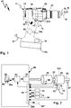
- a hand-held power tool 10 has a housing 11, in the interior of which a drive train 20, 320 is arranged.
- the hand-held power tool 10 is, for example, a screwdriver, drill or both.
- the housing 11 may be conveniently grasped at a handle portion 12 by an operator.
- an upper housing portion 13 which extends like a gun-like angle to the handle portion 12, the drive train 20, 320 is added.
- a hand-held power tool according to the invention can be network-connected, i.
- it can be connected to an electrical supply network or is a battery-powered machine, ie represents a mobile device.
- a switch 15 is provided, with which a drive motor 16 of the hand-held power tool 10 can be turned on or off. Furthermore, it is conceivable to set a speed of the manual power tool 10 with the switch 12.
- a tool holder 18 for receiving a tool 19 is provided, for example, a plug-in receptacle, a chuck or the like.
- the tool 19 is, for example, a drill, a screwdriver bit or the like.
- the hand-held machine tool according to the invention as a milling machine, grinding or polishing machine is of course another useful tool, for example a polishing tool, grinding tool or milling tool or the like.
- the drive motor 16 drives the tool holder 18 via a gear 30. Between the gear 30 and the tool holder 18, a striking mechanism 21 may be connected, so that with the hand-held machine tool 10 even a hammering operation, for example for drilling holes, is possible.
- the drive motor 16, the transmission 30 and the optional hammer mechanism 21 form the drive train 20.
- a transmission 330 is provided instead of the transmission 30.
- the drive motor 16 drives the transmission 30, 330 on the basis of its motor shaft 22.
- the transmission 30 has a switching stage 31 with switchable first and second gear stages 41 and 42.
- the switching stage 31 is followed by a translation stage 32, which further reduces, for example, an output speed of the switching stage 31.
- the translation stage 32 may be, for example, a reduction stage.
- the transmission 30 is designed, for example, as a planetary gear.
- the transmission 30 can be driven via a drive shaft, for example the motor shaft 22.
- a drive wheel 33 is arranged on the motor shaft 22.
- the drive wheel 33 drives the switching stage 31.
- the drive wheel 33 forms a transmission drive 25.
- the drive wheel 33 is a sun gear 34 that drives transfer wheels 35.
- the transmission wheels 35 are, for example, planet wheels 36, which are rotatably mounted on a planetary carrier 37 on planetary axles 40.
- the planetary axles 40 are, for example, rotatable on the planet carrier 37 or the planetary gears 36 rotatably mounted on the planetary axles 40. It can, for example, sliding bearings, ball bearings or needle roller bearings or other bearings between the planetary gears 36 and the planetary axles 40 or the planetary axles 40 and the planet carrier 37 may be provided.
- the planet gears 36 mesh with a first pitch circle diameter 38 with the drive wheel 33rd
- another, second pitch circle diameter 39 of the planet gears 36 is smaller than the pitch circle diameter 38, which contributes to a gear ratio.
- the planet gears 36 mesh with a ring gear 45 and a sun gear 46.
- the ring gear 45 is disposed radially outwardly with respect to the planetary gears 36 and surrounds them annularly.
- the sun gear 46 is provided in the center of the planet gears 36, so to speak.
- the ring gear 45 is assigned to the first gear stage 41 and the sun gear 46 to the second gear stage 42.
- the ring gear 45 forms a blocking gear element 43, the sun gear 46 a blocking gear element 44.
- a respective blocking gear element 43 or 44 is blocked by locking devices 61 or 62 of a switching arrangement 60, it forms a support element for the transmission wheels 35, in the present case the planetary gears 36.
- the respectively locked blocking transmission element 43 or 44 switches, as it were, the respective first and second gear stages 41, 42 active.
- a ratchet gear member 43, 44 is not locked by the associated locking means 61, 62, it can rotate freely so that it does not provide support for the transmission wheels 35.
- An unlocked blocking gear element 43, 44 switches the associated first and second gear stage 41, 42 inactive. Under active and inactive is to be understood that a torque can be transmitted from the drive side to the output side.
- the blocking gear element 43 is arranged with its radially outer circumference, so to speak, directly on or next to the blocking device 61.
- This also has a radially outer support region, namely in the form of a Abstützrads 47 which is connected to the sun gear 46 or in one piece.
- the support wheel 47 is connected to the sun gear 46 through a connecting disc and / or spokes 47A.
- the Abstützrad 46 and the lock gear member 43, so the ring gear 45, have the same radial outer circumferences.
- a passage opening 48 is provided, through which the motor shaft 22 is connected to the drive wheel 33.
- the switching stage 31 drives via a driven gear 49 to the translation stage 32.
- the translation stage 32 is configured as a planetary stage 50.
- the output gear 49 is driven by the planet carrier 37 or in one piece with this.
- the output gear 49 protrudes in front of the planet carrier 37.
- the planet gears 51 are arranged in the interior of a ring gear 54, which is fixed relative to the housing 11 of the hand-held power tool 10 or a transmission housing 90 of the transmission 30.
- the ring gear 54 is fixed in place, for example, on a housing portion 93 of the gear housing 90. Consequently, therefore, the planet gears 51 roll on the inner circumference of the ring gear 54 from.
- the planetary gears 51 are rotatably supported, for example, on the planetary axles 53.
- the planetary axles 53 have an additional function, namely by coupling the planetary carrier 52 with an output shaft 54 of the transmission 30 in a torque-proof manner.
- the planetary shafts 53 protrude on opposite sides in front of the planetary carrier 52, on the one hand rotatably supporting the planet gears 51, on the other hand coupling a transmission element 56 for the output shaft 55 rotatably or are firmly connected thereto.
- the transmission element 56 receives, for example, a shaft portion 57 of the output shaft 55 or is fixedly connected to this shaft portion 57.
- the output shaft 55 is rotatably supported, for example, on bearings 59 on a portion 91 of the transmission housing 90.
- a tool section 58 which has the tool holder 58 on its end face, protrudes in front of a front side 92 of the gear housing 90.
- the transmission housing 90 is closed by a cover 95.
- the lid 95 has a passage opening for the motor shaft 22 or other drive shaft.
- the transmission 30 can be advantageously encapsulated, may have seals or the like, for example, at an opening on the front side 92, where the output shaft 55, the transmission housing 90 penetrates.
- the two locking devices 61, 62 are each designed as freewheels.
- the power flow or the torque transmission from the transmission drive 25, for example, from the drive wheel 33 or the motor shaft 22, to a transmission output 25, for example, the output gear 49 or the output shaft 58 of the transmission 30 can by a simple reversal of direction of the drive motor 16 between the Gear stage 41 and the gear stage 42 are switched.
- the direction of rotation of the drive motor 16 is quickly switchable, in particular because the drive motor 16 in an advantageous embodiment of the invention is a so-called brushless motor, eg electronically commutated motor.
- the locking device 62 releases the lock gear member 44, so that no power flow is possible through the second gear 44.
- the sun gear 46 turns free.
- the other inhibitor 61 then operates, i. It locks the associated support member or blocking gear element 43, namely the ring gear 45.
- the transmission wheels 35 in this case the planetary gears 36, at the stationary with respect to the gear housing 90 ring gear 45 roll and thus a power flow or torque transmission from the transmission drive 25 for Gearbox output 26 allow.
- the gear stages 41, 42 each provide a torque ratio and speed change between on the one hand the transmission drive 25 and on the other hand the transmission output 26 ready.
- the operator can actively switch the direction of rotation of the drive motor 16 for this purpose.
- a controller 80 of the Manual machine tool 10 causes the reversal of rotation automatically, for example, as a function of torque and / or speed of the drive motor 16.
- the controller 80 could be an analog controller that monitors its torque output with a simple current monitoring, for example, of the drive current leading to the drive motor 16, thus switching the direction of rotation accordingly.
- a digital control for example by means of corresponding digital circuits, in particular a microprocessor 81.
- This operates on the basis of a software program 86 which is stored in a memory 82 which the processor 81 can read.
- the processor 81 On the basis of the software program 86 or another software program, the processor 81, for example, an output stage 83 to drive the drive motor 16 to control.
- the output stage 83 contains, for example, power electronics.
- the controller 80 receives signals, for example, from the switch 15 or a Drehbaumeinstellelement 23, with which a speed of the drive motor 16 can be predetermined by the operator.
- the controller 80 changes the direction of rotation of the drive motor 16, for example, so that the transmission 30 switches back, for example, from the second gear stage to the first gear stage.
- the controller 80 reversely changes the rotational direction of the drive motor 16, so that the transmission 30 shifts from the first gear stage to the second gear stage, so that the drive motor 16 can rotate at a lower speed.
- the locking devices 61, 62 are, so to speak, sandwiched between the blocking gear elements 43 and 44 on the one hand and a housing section 94 of the gear housing 90. Thus, so the lock means 61, 62 so to speak radially outer components of the transmission 30. Because the locking means 61, 62 are arranged radially outward, they are also easy to intervene outside, so for example for a changeover of the respective reverse direction accessible.
- the two locking devices 61, 62 designed as freewheels can be shifted in relation to their locking direction and freewheeling direction.
- the locking devices 61, 62 include a common support ring 63, which could be described as a freewheel ring.
- each locking device 61, 62 it would also be readily possible for each locking device 61, 62 to be designed as a separate freewheel device, i. that there are no common components.
- the support ring 63 is fixed relative to the transmission housing 90.
- support body 64 in particular bolts or the like, between the inner circumference of the gear housing 90, so the housing portion 94, and the outer periphery of the support ring 63 is positively inserted and hold the two components form-fitting together.
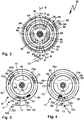
- the support ring 63 has at its inner periphery rotationally offset several, for example three, freewheel recesses 65, in each of which a locking element 68 or 69, in particular a ball, roller or pin, a respective locking device 61 is 62 out.
- the locking devices 61 have mutually separate locking elements 68, 69, so that they can have opposite direction of freewheeling in and locking directions.
- the blocking elements 68, 69 are mounted between the outer peripheries of the locking gear elements 43, 44 and the inner circumference of the support ring 63 in the region of the respective freewheel recesses 65.
- the locking elements 68, 69 with respect to a rotational axis D, to which the locking gear elements 45, 46, namely the ring gear 45 and the combination of sun gear 46 and Abstützrad 47th rotate, on the outer circumference of the respective blocking gear element 43, 44 are moved, namely in the region of the freewheel recesses 65 in or out of these, in clamping slope or constrictions 66, 67th
- the blocking elements 68, 69 of a locking device 61 or 62 are in the freewheel recesses 65, the respective locking device 61 or 62 is in free-running. However, if the locking elements 68, 69 are moved in the direction of the clamping slope in or constrictions 66 or 67, the locking device 61, 62 is locked. The associated blocking gear element 43, 44 is then blocked by the arranged on its outer circumference locking elements 68, 69, which are located in one of the clamping bevels 66 or 67 and supported on the support ring 63, with respect to a rotation about the rotation axis D, so that the blocking gear member 43, 44 can serve to support the planet gears 36 and thus the respective gear stage 41 or 42 is active.
- the blocking direction or free-wheeling direction of a respective locking device 61, 62 is switchable.
- a switching device 70 is provided, which is easily actuated by a single, manual actuator 71 by an operator.
- the actuating element 71 is configured, for example, as a projection in front of a switching element 72 designed as a ring, for example, which is rotatable about the axis of rotation D.
- pin-like guide elements 73 which are also referred to below with 73a and 73b, in the direction of the locking elements 68, 69, wherein a respective locking element 68, 69 is arranged between pairs opposite guide elements 73.
- the locking elements 69 are adjusted in the direction of the clamping bevels 66, so that the locking device 61 in a rotational direction D1 blocks or blocks the support member or locking gear member 44.
- the guide elements 73b hold the locking elements 69 in the freewheel recesses 65.
- the direction of rotation D2 thus corresponds to a freewheeling direction F1, the direction of rotation D1 a reverse direction S1 of the locking device 62 in the position according to Figures 3 or 4 ,
- the switching device 70 is provided with a fixing device 100.
- the fixing device 100 comprises a clamping device 101.
- the clamping device 101 has a clamping bevel 102, as well as a clamping bevel 103, against which the actuating element 71 in the switching position T1 in accordance FIGS. 3 and 4 each runs up.
- a rotation of the switching element 72 counterclockwise not shown in detail
- a switching position T2 can be reached, in which the support wheel 47 and the sun gear 46 rotate in the direction of rotation D1 and can not rotate in the direction of rotation D2, that is locked.
- a clamping slope in the form of the clamping slope 103 is provided for this switching position T2, the only by a corresponding position of the actuating element 71 in FIG. 4 is indicated.
- each have a spring element 75 is provided between the guide elements 73 and the locking elements 68, 69 each have a spring element 75 is provided.
- the spring elements 75 bias the locking elements 68, 69 in the direction of the locking position, i. in the direction of the clamping bevels 66, 67 into it.
- the locking elements 68, 69 are already loaded in the direction of the locking position, so that the blocking function or from supporting function of the locking gear elements 43, 44 is available as directly as possible.
- the blocking elements 68, 69 are advantageously movably decoupled from each other.
- a decoupling ring 74 between the locking elements 68, 69 is arranged.
- the locking direction and the freewheeling direction of the locking devices 61, 62 can be reversed in opposite directions, namely by the switching device 70. Namely, when the actuating element 71 is actuated about the axis of rotation D, make the guide elements 73 this rotational movement, so that they starting from a middle position about accordingly FIG. 2 in relation to the rotational axis D rotationally offset position, for example, a switching position T1 for clockwise or a switching position T2 for left-hand rotation of the tool holder 18 (facing the front side according to FIGS. 3, 4 ) are adjustable.
- the blocking direction S1 and the freewheeling direction F1 can be reversed in opposite directions.
- the controller 80 adjusts the direction of rotation of the drive motor 16 as a function of the position of the switching device 70 for clockwise or anti-clockwise rotation so that it switches to clockwise rotation or vice versa in a gear stage occupied before switching the direction of rotation 41 or 42 starts.
- a sensor 85 is arranged on the switching device 70 in order to detect their respective switching position.
- the sensor 85 is, for example, an electrical contact, a non-contact contact or the like.
- an inductive, optical or capacitive measuring element may be provided as a sensor, but also an electrical contact switch or the like.
- the first gear stage 41 is a negative gear
- the second gear 42 is a plus gear, so that by a simple reversal of the drive motor 16 in the transmission 30, the gear stages 41 and 42 are switchable, but so that no reversal of rotation is connected to the transmission output 26.
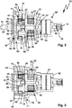
- the powertrain 320 includes a transmission 330, which is constructed with respect to a switching stage 331 similar to the transmission 30 and its switching stage 31. However, different is the operating concept (with a switching device 370) in a switching arrangement 360, which corresponds functionally to the switching arrangement 60 , as well as the output side of the gearbox 330, where instead of a simple Planet stage or a simple reduction gear as in the embodiment according to FIGS. 5 and 6 a switchable gear assembly 350 is provided. As far as the same or similar components in the embodiment according to FIGS. 5 and 6 and the other embodiment according to FIGS. 8 and 9 are present, they are provided with the same reference numerals, but to illustrate differences in part with increased by 300 reference numerals.
- the switching stage 331 drives with its transmission output 25 to a switching stage 332, which can work as a reduction stage in terms of speed reduction, but does not have to.
- the drive motor 16 drives a drive wheel 333 via the motor shaft 22.
- a receptacle 333a is provided on the drive wheel 333 or a shaft element connected thereto for receiving and rotationally fixed coupling of the motor shaft 22.
- the drive wheel 333 forms a sun gear 334 which meshes with planet gears 336.
- the planetary gears 336 advantageously form transmission wheels 35.
- the planet gears 336 are rotatably mounted on a planet carrier 337.
- planetary axes 40 are rotatably mounted on the planet carrier 37 or the planet carrier 336 are rotatably mounted on the planetary axles 40.
- the planet gears 336 have different pitch circle diameters 38, 39 as the planetary gears 36. With the pitch circle diameter 38, the planet gears 336 mesh with the sun gear 334, while the smaller pitch circle diameter 39 provides that the planet gears 336 engage a ring gear 345, thus comb or the ring gear 345 can take-along.
- the switching stage 331 has a first gear stage 341 (corresponding to the gear stage 41) and a second gear stage 342 (corresponding to the gear stage 42), between which the switching stage 331 is switchable based on a reversal of the direction of rotation of the drive motor 16.
- the planet gears 336 are so to speak radially inwardly supported, namely can roll on a sun gear 346, which forms part of a blocking gear member 344.
- the blocking gear element 344 corresponds to the blocking gear element 44 and has a passage opening 48 for the motor shaft 22.
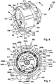
- the switching arrangement 360 comprises a blocking device 361 for blocking or releasing the blocking gear element 343 and a blocking device 362 for blocking or releasing the blocking gear element 344
- FIG. 11 schematically illustrated locking elements 368, 369 are based on a support ring or freewheel ring 363 from (similar to the components 68, 69 and 63) and are preferably by in FIG. 10 visible spring elements 375 (corresponding to the spring elements 75) loaded.
- the support ring 363 is fixed relative to the transmission housing 390.
- supporting body 364 in particular supporting projections, between the inner circumference of the gear housing 390, in particular the housing portion 394, and the outer periphery of the support ring 363 provided to hold the two components form-fitting together.
- the support bodies 364 are, for example, support projections which engage in corresponding support receptacles 364A of the transmission housing 390.
- the actuator 371 protrudes radially outward in front of a transmission housing 390 of the transmission 330, so it can be easily grasped by the operator.
- the actuator 371 is rotatably mounted on the support ring or freewheel ring 363 or passes through this.
- the actuator 371 is provided on a housing portion 394 of the gear housing 390, in which the switching stage 331 is received.
- the actuator 371 is rotatably connected to the switching element 372.
- a portion 374 of the example rod-shaped or annular actuator 371 is coupled to the switching element 372.
- the switching element 372 is, for example similar to the switching element 72 annular. In contrast to the switching element 72, however, the switching element 372 is arranged between the gear stages 341, 342 and between the blocking gear elements 343, 344. For example, a protrusion 372a engages an intermediate portion or space between the ring gear 345 and the support gear 347 of the ratchet gear member 344.
- the switching device 370 can also be fixed by a fixing device 300, for example a fixing device in the manner of the fixing device 100.
- a fixing device 300 may be provided with a locking device 301.
- a locking element 301 for example a fork, a pin or the like, is displaceably mounted on the transmission housing 390 or housing 11.
- the locking element 301 can be brought out of engagement with the actuating element 371 in an unlocking position E, in a locking position V in engagement with the actuating element 371 (FIG. FIG. 11 ).
- the actuating element 371 In the locking position V, the actuating element 371 is no longer rotatable, for example with respect to the axis of rotation D, so that the switching element 362 remains in the respective switching position T1 or T2.
- the transmission 390 is also provided on its side facing the drive motor 16 by a cover, here a cover 395. locked. On a side facing away from the cover 395, next to the housing portion 394, there is a further housing portion 393, which receives the gear assembly 350, that is, the switching stage 332.
- the housing section 393 is closed by a cover 391, on whose front side or front side 392 the output shaft 55 is coupled to the tool holder 18.
- the tool shaft 18 is driven by the gear stage or shift stage 332, which in turn is in turn coupled to the transmission output 26 of the switching stage 31.
- the gear output 26 includes a driven gear 349, which is for example fixedly connected to the planet carrier 337, for example, is integral therewith.
- the output gear 349 forms a sun gear with which planet gears 351 of the gear assembly 350 mesh.
- the planet gears 351 are rotatable with respect to a planetary carrier 352, for example, by being rotatably supported on planetary axles 353 or by the planetary axles 353 being rotatably supported on planetary carriers 352.
- the gear assembly 350 couples a ratchet wheel 354, such as a ring gear, the gear assembly 350, the planetary gears 351 rotatably connected to the planet carrier 337.
- the planet carrier 337 has, for example on its outer periphery a toothing 337a, which can engage with internal teeth of the ratchet wheel 354. Also in engagement with this gearing or lying next to this gearing is a respective planetary gear 351st
- the planet gears 351 mesh with the internal teeth of the ratchet wheel 354, so roll on this.
- the ratchet wheel 354 in turn is rotationally fixed with respect to the transmission housing, for example by means of an external toothing 354a of the ratchet wheel 354, which is in engagement with an internal toothing 354b on the housing 390, for example the cover 391.
- the internal toothing 354b is radially inward, the external toothing 354a radially outward.
- the shiftable transmission assembly 350 can be manually switched, for example, by an actuating element 310 which is displaceably mounted in or on a receptacle 311 of the transmission housing 390.
- the actuating element 310 is coupled in terms of movement by means of a coupling element 312 to the switching wheel 354, but could also be fixedly arranged on the switching wheel 354.
- the coupling element 312 includes, for example, pins, brackets or the like other components, which allows a power transmission from an outside of the transmission case 390 in the interior thereof, where the switching wheel 354 is arranged.
- the receptacle 311 forms a sliding bearing or a sliding receptacle, in which the actuating element 310 is received linearly displaceable.
- the actuating element 310 is coupled in motion or in one piece with a manually engageable actuating handle 313, for example a ring or slider.
- the actuating handle 313 projects, for example, in front of the housing 11 of the hand-held power tool 10, so it is easy to grasp.
- a concept for switching the gear assembly 350 is an actuator 387, for example, an electromagnet, an electric motor or the like (a pneumatic drive is also possible).
- the actuator 387 is configured and provided for an adjustment of the switching wheel 354, that is to say a switching element of the gear arrangement 350, between at least two switching positions.
- the actuator 387, the ratchet 354 between the switch positions according to FIGS. 8 and 9 adjust back and forth.
- the actuator 387 is driven, for example via an electrical switch 24a on the housing 11 of the hand-held machine tool 10.
- the actuator 387 is housed protected in the interior of the transmission housing 390.
- the representation of the actuator 387 is to be understood as an example.
- the controller 80 is preferably designed to control the activation of the actuator 387.
- it has a switching output 388 for switching the actuator 387.
- the controller 80 can thus automatically switch the gear stage or shift stage 331, for example, and advantageously also the shiftable gear arrangement 350 or the shift stage 332.
- the gear stage or shift stage 331 for example, and advantageously also the shiftable gear arrangement 350 or the shift stage 332.
- sensors can also be provided on the output area, which interacts with the controller 80.
- a sensor 87 for detecting rotational speed and / or torque and / or rotational direction or the like, for example a tachometer, a torque detection, may be provided on the tool shaft or output shaft 55.
- a sensor 88 for example, an optical sensor, a Hall sensor or the like, the drive motor 16, for example, detect its torque and / or direction and / or speed.
- a sensor 89 in particular for speed detection and / or torque detection and / or rotational direction detection, may be provided at the input of the transmission 30, 330, for example on the motor shaft 22.
- the sensors 87, 88, 89 report their respective sensor signals via the input interface 84 of the controller 80, which adjusts, for example, the speed and / or direction of rotation of the drive motor 16 by means of its software program 86 in order to switch the transmission 30, 330 in this way. Based on the signals of the sensors 87,1888, 89, the controller 80 but the actuator 387 control.
- the sensor signals of the sensors 87, 89, 88 can also be used to control the drive motor 16 and / or to control and in particular also the transmission 330, in particular its switching stage 332, to switch.
- an operator can, for example, specify a desired maximum speed or setpoint speed SD of the output shaft 55.
- a desired maximum speed or setpoint speed SD of the output shaft 55 For example, the operator can specify a maximum speed of 2000 to 4000 rpm for a drilling operation, and a maximum speed of 500 to 2000 rpm for a screwing operation.
- an optional torque setting element 24 for example a rotatable adjusting element, a slide or the like
- the operator can, for example, specify a desired maximum torque or setpoint torque SM on the output shaft 55.
- a desired maximum torque or setpoint torque SM on the output shaft 55.
- a speed control or torque control may be advantageous, for example, in a milling cutter or saw.
- a touch-sensitive display can be provided, which displays the set values SM and / or SD.
- a control module 86a of the software program 86 can, for example, based on the maximum values or target values SM and / or SD and the feedback of the set values, namely the actual values, the sensors 87, 88, 89 supply, the drive motor 16 and / or drive the power amplifier 83 and / or rules. Furthermore, the control module 86a can also control the actuator 387 in accordance with these values via the switching output 388 in accordance with the switching of the gear stage 332.
- the controller 80 controls the actuator 387 to shift the transmission 332 from the shift position in which the shift 332 does not realize speed reduction relative to the transmission output 26 (FIG. FIG. 10 ), in the switching position, in which the gear stage 332 acts as a reduction gear ( FIG. 11 ), ie the position at which the planet gears 351 roll in the ring gear 354.
- the planetary axes 353 or 53 may be part of a spindle stop, i. that a rotational blocking on the output side of the gear 30, 330 readily at this point is feasible.
- the switching element 372 is sandwiched between the locking devices 61, 62.
- An alternative operating concept or switching concept is in the FIGS. 8, 9 . 12, 13 for the transmission 330.
- FIG. 9 designed as a freewheel device or freewheel blocking device 361 shown in somewhat greater detail.
- the switching element 472 is designed, for example, as a disk body.
- the switching element 472 of the switching device 470 is rotatably mounted about the rotational axis D in the gear housing 330.
- 390 rolling elements 476 are provided between the switching element 472 and the transmission housing, in particular balls.
- a three-point bearing that is, for example, at an angle of 120 ° each have a rolling element 476 is provided between the switching element 472 and the inner circumference of the gear housing 390.
- the rolling elements 476 pockets or the like other bearing receptacles 477 provided on the gear housing 390 or 472 as in the embodiment of the switching element.
- the switching element 472 are guide elements 373 parallel to the rotation axis D in recesses 363A between the support ring 363 and mounted in the support ring 363 locking gear member 344.
- clamping bevels 366, 367 provided in the recess 363A protrusions.
- a blocking element 369A and 369B is arranged in each case.
- the locking elements 369 A, 369 B are held by the guide members 373 close to the projections or at the clamping slopes 366, 367.
- the guide members 373 project into the recesses 363A, for example, in the manner of rods or guide projections. Since the recesses 363A are coaxial with one another, a respective guide element 373 can pass through the recesses 363A of both locking devices 361, 362. Thus, with a single switching element 472, both the locking device 361 and the locking device 362 can be switched simultaneously in terms of their locking direction and freewheeling direction.
- the guide elements 373 are arranged between a respective blocking element 369A, 369B.
- a respective guide element 373 acts directly on a respective blocking element 369A or 369B in the direction of the release direction of rotation, see, for example, a detail section J in FIG FIG. 12 whereby the blocking element 369 B is held in a detailed section J away from the clamping bevel 367 and in the freewheel recess 365, so that the blocking gear element 344 can rotate freely in the direction of rotation D 2, for example.
- the other blocking element 369A is, as it were, acted upon indirectly by the adjacent guide element 373A in the direction of the blocking position, ie in the direction of the clamping bevel 367, namely by means of a spring element 375.
- the adjacent guide element 373B acts on the locking element 369B visible in the detail section J in the direction of the clamping bevel 366.
- the spring elements 373 comprise actuating bodies 375A, which are mounted displaceably relative to one another. Disposed between the actuators 375A is a spring 375B that separates the two actuators 375A in a sense acted upon.
- the actuators 375A are L-shaped, with the short L-leg acting on a locking member 369A or 369B, for example.
- the spring 375B for example a coil spring, is guided between the actuators 375A.
- a guide pin or guide projection extending, for example, between or formed on the actuators 375A extends through an internal space of a respective spring 375B.
- the spring elements 375 form a total of a spring assembly 375C.
- the arrangement when freewheeling or the locking device 361, 362 made such that between the locking elements 369, the guide elements 373 and the spring elements 375 little movement play exists, ie that the aforementioned components are annularly arranged within the recess 363A play with little effort.
- a fast, efficient switching of the directions of rotation at the output of the transmission 330 can be effected when the blocking directions of the locking devices 361, 362 are switched as explained below.
- the so-called play-free concept between the locking elements 368, 369, the guide elements 373 and the spring elements 375 preferably provides that a guide member 373 via a locking element 369A or 369B, which is held in each case in the region of a freewheel recess 365, the spring member 375 charged, which in turn again resiliently another locking element 369 A, 369 B is supported.
- each of the guide members 373 in the clockwise direction or in the rotational direction D1 supports a blocking element 369B such that it is held in the freewheel recess 365.
- This respective blocking element 369A acts on the spring element 375 adjacent in the direction of rotation D1, which in turn holds a blocking element 369A in the region of the clamping slope 367.
- the locking elements 369A can immediately abut the clamping slopes 367 and provide deadlock.
- this functionality also applies to the locking device 361, where the locking elements 368 are correspondingly arranged relative to the guide elements 373 and the spring elements 375 and supported by these in each case.
- the locking device 362 in this case a freewheel, set in a reverse direction S1 (the blocking gear element 344 can rotate in the direction of rotation D2, not in the direction of rotation D1), in the switching position T2 in a reverse direction S2, in which Locking gear element 344 can rotate in the direction of rotation D1 and is locked in the direction of rotation D2.
- the locking device 361 the blocking directions in the switching positions T2 and T1 are provided in relation to the locking device 362 opposite direction of rotation.
- a manual actuator 420 is configured, for example, as a slider.
- the actuating element 420 is displaceably mounted on a sliding guide 424 with respect to the housing 11.
- a respective longitudinal end position of the actuating element 420 with respect to a sliding axis or adjusting axis along the sliding guide 424 is respectively an actuating arm 421 or 422 with its respective operating portion 423 in front of the housing 11 before or at least before the housing 11 before than the other actuating arm.
- the operator has a visually easily recognizable signal, which shift position or switching position, the switching device 470 occupies and thus also with which direction of rotation the gear 330, the tool 19 drives.
- a holder 426 for a sensor guard 425 for example, a permanent magnet
- sensor 85 for example an inductive sensor, Hall sensor, reed contact or similar other contactlessly actuatable sensor, can be actuated, so that in this way controller 80 learns the respective switching position of switching device 470 and drive motor 16 in the sense of drives appropriate direction of rotation. This has already been described in principle.
- a toothed gear is present between the actuating element 420 and the switching element 472, for example, a toothed gear is present.
- a toothing which meshes with a toothed rack or a toothed rack section on the switching element 472, could be provided on the radially outer circumference of the outer side round or a roller element representing switching element 472.
- a transmission gear 430 which includes a lever mechanism 431.
- the lever mechanism 431 includes, for example, a rocker arm as a transmission element 421, with which a sliding operation or linear adjustment of the actuating element 420 can be converted into a rotational movement of the switching element 472.
- the transmission gear 430 simultaneously forms a deflection gear, which converts a linear movement into a rotational movement.
- the transmission element 471 engages with a drive arm 432 in a recess 327 of the actuating element 420.
- the transmission element 471 is mounted on a bearing axis 434 on the switching element 472 pivotable or tiltable.
- a fixing device 400 is realized in connection with the rocker arm concept or the transfer element 471.
- the fixing device 400 is suitable for the bistable fixing of the locking devices 461, 462 in the respective switching positions T1 and T2.
- the fixing device 400 has a latching device 401 or forms a latching device 401.
- the fixing device 400 has a latching element 402, which is displaceably mounted in a bearing or a bearing receptacle 403 on the switching element 472.
- An actuating projection of the locking element 402 presses on an end face of the transmission element 471, specifically the output arm 433.
- the latching force or actuating force required for this purpose is provided by a spring arrangement 404.
- the spring assembly 404 has springs 405.
- the spring assembly 404 is supported in a chamber 406 on the switching element 472 and acts on the locking element 402, which in turn, the rocker arm or the transmission element 472 loaded in its respective Schwenkendwolfen associated with the switching positions T1 and T2.
- the output arm 433 is provided with a rounded end 436 at the end, so that the actuating arm of the latching element 402 slides along the rounding 463.
- the latching element 402 thus loads the transmission element 472 in the direction of its pivot end positions, so that the transmission element 471 is, as it were, forcibly loaded in its respective pivoting end positions.
- a spring force of the spring assembly 404 is designed so that it exceeds the sum of all the forces of the spring elements 375.
- a locking device 442 provided instead of the latching device 401 or in addition to the latching device 401 can provide that, for example, a latch 440 can be brought into a recess 441 on the actuating element 420.
- a lock can be realized.
- the locking element 440 for example, a linearly displaceably mounted on the housing slide 11 or bolt, thus providing additional security.
- the spring force of the spring assembly 404 could also be designed smaller.
- a fixing device is also useful in the case of a motor drive for a switching device.
- a motor drive 429 for example an electromagnetic drive, a coil arrangement or the like, is provided for driving the actuating element 420 and / or the switching device 470 between the switching positions T1 and T2.
- the motor drive 429 is, for example, an actuating projection 428 which projects from the actuating element 420.
- the drive 429 must be energized only briefly to switch between the switching positions T1 and T2. Then, the switching device 470 is held by, for example, the fixing device 400 in the respective switching position T1 or T2.
- a fixing device 500 ( FIGS. 14, 15 ) provides, for example, a latching concept, which corresponds to a latching element 502 on an actuating element 520, which in principle corresponds to the actuating element 420.
- a latching element 502 of a latching device 501 is arranged on the actuating element 520, which is motion-coupled to the transmission element 471 in the manner already described.
- the latching element 502 has a latching arm 503, on which a latching projection 504 is provided.
- the locking projection 504 slides along a detent gate 505, which is stationary with respect to the housing 11 of the power tool 10 or the gear housing 390.
- the detent gate 505 has, for example, inclined surfaces 506, 507, which are arranged on a gate body 508 and are provided on mutually opposite sides of a detent projection 509.
- the latching projection 504 is positioned, for example, on the inclined surface 507, in the switching position T2 on the inclined surface 506.
- the latching element or latching projection 504 thus comes to lie in the switching positions T1, T2 respectively on an inclined surface 506 or 507 and must be assigned via the resistance of the latching projection 509 between the switching positions T1 and T2 Positions with respect to the locking projection 509 are adjusted. Consequently, the latching device 501 engages laterally next to the latching projection 509 on one of the inclined surfaces 506 or 507 with respect to the switch positions T1, T2.
- a spring force of the latching arm 503 is advantageously designed so that it can support the restoring moments or reaction moments of the spring elements 375.
- An additional or alternative concept additionally provides for a jamming of the actuating element 520.
- the actuating element 520 respectively run on clamping bevels 510, 511 in the switching positions T1 and T2 associated longitudinal end positions, in particular with the operating portions 423.
- a clamping bevel in the area between the actuating portions 423 on Betuschistselement 420. Consequently, therefore, the clamping bevels 510, 511 do not necessarily have to act on the actuating sections 423 or be arranged along the outside.
- a corresponding arrangement of clamping bevels in the middle section of the actuating element 520 could look similar to the arrangement of the locking in the fixing device 600 according to FIG FIGS. 16, 17 ,
- a locking device 601 forms a fixing device 600.
- the fixing device 600 cooperates with an actuating element 620, which in itself corresponds to the actuating element 520 or 420, ie in principle serves as an actuating element for a rocker armature or transmission 430.
- latching with, for example, the spring-loaded latching element 402 is optionally possible, but not absolutely necessary.
- the locking element 402 may be fixed in place by a fixing body 407.
- a stationary driving recess 435 could also be provided, that is, for example, that the output arm 433 is unloaded from the front side and only exerts a torque about the axis of rotation D.
- a spring arrangement is provided in the manner of the spring assembly 404, so that an additional fixing force or bistable holding force is provided.
- the sum of the restoring forces the fixing forces of this fixing device with the spring arrangement 404 (instead of the fixing body 407) and the respective latching device 501 or the locking device 601 of the fixing device 600 described below is advantageously greater than the sum of all the reaction forces by the spring elements 375.
- the latching device 601 comprises a latching element 602 provided fixedly with respect to the housing 11 or the gear housing 390.
- the latching element 602 comprises, for example, a spring element which projects with a latching projection 604 in the direction of the actuating element 620.
- the actuating element 620 has the switching positions T1 and T2 associated with or suitably positioned for latching receptacles 605, 606, for example, in the section between the actuating portions 423.
- the latching projection 604 engages in one of the two latching receptacles 605 or 606 in the sliding positions of the actuating element 620, the Switch positions T1 or T2 correspond.
- An additional or alternative fixing effect may be a fixing device 700 with a magnet arrangement 701.
- magnetic elements 703, 704 are provided on the actuating element or slide 620, in particular in the region of the actuating sections 423. Opposed thereto are further magnetic elements 702, 704 which attract the magnetic elements 703, 705.
- the actuator 620 when the actuator 620 is in a respective end position corresponding to one of the switch positions T1 or T2, for example, as in FIG. 16 represent the magnetic elements 704, 705, while the distance between the magnetic elements 702 and 703 is greater, so there is a lower attraction or holding force is provided. This allows a bistable position.
- the magnetic elements 702-704 or elsewhere could be arranged.
- the magnetic elements 702-704 are, for example, permanent magnets or combinations of permanent magnet and ferromagnetic element.
- ferromagnetic region can be provided on the outside of the housing 11, which interact with the permanent magnetic magnet elements 703, 705 in the actuating element 620.
Landscapes
- Engineering & Computer Science (AREA)
- Mechanical Engineering (AREA)
- Structure Of Transmissions (AREA)
- Portable Power Tools In General (AREA)
Description
Die Erfindung betrifft eine Hand-Werkzeugmaschine, insbesondere ein Schraubgerät und/oder Bohrgerät, mit einem Antriebsmotor zum Antreiben eines Getriebe-Antriebs eines Getriebes, das einen Getriebe-Abtrieb zum Antreiben einer Werkzeugaufnahme der Hand-Werkzeugmaschine und eine erste Getriebestufe und eine zweite Getriebestufe aufweist, wobei das Getriebe eine erste Sperreinrichtung zum Sperren eines ein Sperrgetriebeelement bildenden Getriebeelements der ersten Getriebestufe und eine zweite Sperreinrichtung zum Sperren eines ein Sperrgetriebeelement bildenden Getriebeelements der zweiten Getriebestufe aufweist, wobei die Getriebestufe mit dem jeweils gesperrten Sperrgetriebeelement ein Drehmoment vom Getriebe-Antrieb zum Getriebe-Abtrieb überträgt, wobei eine Drehrichtung des Antriebsmotors umschaltbar ist und in Abhängigkeit von der Drehrichtung des Antriebsmotors die erste Getriebestufe oder die zweite Getriebestufe ein Drehmoment vom Getriebe-Antrieb zum Getriebe-Abtrieb überträgt, wobei die Sperreinrichtungen in einer Sperrrichtung das jeweilige Sperrgetriebeelement sperren und in einer Freilaufrichtung freigeben, und wobei eine Schalteinrichtung zum Umschalten der Sperreinrichtungen oder mindestens einer der Sperreinrichtungen zwischen einer ersten Schaltstellung und einer zweiten Schaltstellung vorgesehen ist, in denen die Sperrrichtungen der mindestens einen Sperreinrichtung oder der jeweiligen Sperreinrichtung einander entgegengesetzt sind.The invention relates to a hand-held power tool, in particular a screwdriver and / or drill, with a drive motor for driving a transmission drive of a transmission having a transmission output for driving a tool holder of the hand-held machine tool and a first gear stage and a second gear stage wherein the transmission comprises a first locking device for locking a transmission element forming a blocking transmission element of the first transmission step and a second locking device for locking a transmission element of the second transmission step forming a blocking transmission element, wherein the transmission step with the respectively locked blocking transmission element generates a torque from the transmission drive to the transmission Output transmits, wherein a direction of rotation of the drive motor is switchable and depending on the direction of rotation of the drive motor, the first gear stage or the second gear stage, a torque from the transmission drive to the transmission output via carries, wherein the locking devices lock the respective blocking gear member in a locking direction and release in a freewheeling direction, and wherein a switching means for switching the locking means or at least one of the locking means between a first switching position and a second switching position is provided, in which the locking directions of the at least one locking device or the respective locking device are opposite to each other.
Eine Hand-Werkzeugmaschine dieser Art ist beispielsweise in
Es ist daher die Aufgabe der vorliegenden Erfindung, eine verbesserte Hand-Werkzeugmaschine mit einer verbesserten Schaltbarkeit ihres Getriebes bereitzustellen.It is therefore the object of the present invention to provide an improved hand machine tool with improved shiftability of its transmission.
Zur Lösung der Aufgabe ist bei einer Hand-Werkzeugmaschine der eingangs genannten Art vorgesehen, dass sie eine Fixiereinrichtung zum Fixieren der mindestens einen Sperreinrichtung oder mindestens einer der Sperreinrichtungen oder beider Sperreinrichtungen in der jeweiligen Schaltstellung aufweist.To solve the problem is provided in a hand-held machine tool of the type mentioned that it has a fixing device for fixing the at least one locking device or at least one of the locking devices or both locking devices in the respective switching position.
Die Erfindung betrifft ferner eine Hand-Werkzeugmaschine, insbesondere ein Schraubgerät und/oder Bohrgerät, mit einem Antriebsmotor zum Antreiben eines Getriebe-Antriebs eines Getriebes, das einen Getriebe-Abtrieb zum Antreiben einer Werkzeugaufnahme der Hand-Werkzeugmaschine und eine erste Getriebestufe und eine zweite Getriebestufe aufweist, wobei das Getriebe eine erste Sperreinrichtung zum Sperren eines ein Sperrgetriebeelement bildenden Getriebeelements der ersten Getriebestufe und eine zweite Sperreinrichtung zum Sperren eines ein Sperrgetriebeelement bildenden Getriebeelements der zweiten Getriebestufe aufweist, wobei die Getriebestufe mit dem jeweils gesperrten Sperrgetriebeelement ein Drehmoment vom Getriebe-Antrieb zum Getriebe-Abtrieb überträgt, wobei eine Drehrichtung des Antriebsmotors umschaltbar ist und in Abhängigkeit von der Drehrichtung des Antriebsmotors die erste Getriebestufe oder die zweite Getriebestufe ein Drehmoment vom Getriebe-Antrieb zum Getriebe-Abtrieb überträgt, wobei die Sperreinrichtungen in einer Sperrrichtung das jeweilige Sperrgetriebeelement sperren und in einer Freilaufrichtung freigeben, und wobei eine Schalteinrichtung zum Umschalten der Sperreinrichtungen zwischen einer ersten Schaltstellung und einer zweiten Schaltstellung vorgesehen ist, in denen die Sperrrichtungen der jeweiligen Sperreinrichtung einander entgegengesetzt sind, dadurch gekennzeichnet, dass sie eine Fixiereinrichtung zum Fixieren der Sperreinrichtungen in der jeweiligen Schaltstellung aufweist.The invention further relates to a hand-held power tool, in particular a screwdriver and / or drill, with a drive motor for driving a transmission drive of a transmission, the transmission output for driving a tool holder of the hand-held machine tool and a first gear stage and a second gear stage wherein the transmission comprises a first locking means for locking a transmission element forming a blocking gear element of the first gear stage and a second locking means for locking a gear element of the second gear stage forming a blocking gear element, wherein the gear stage with the respective locked blocking gear element torque from gear drive to gearbox -Abtrieb transmits, wherein a direction of rotation of the drive motor is switchable and depending on the direction of rotation of the drive motor, the first gear stage or the second gear stage, a torque from the transmission drive to gearbox Abtrie b transmits, wherein the locking devices in a blocking direction lock the respective blocking gear element and release in a freewheeling direction, and wherein a switching device for switching the locking devices between a first switching position and a second switching position is provided, in which the locking directions of the respective locking device are opposed to each other characterized in that it comprises a fixing device for fixing the locking devices in the respective switching position.
Es ist ein Grundgedanke, dass die Fixiereinrichtung die jeweils eingestellte Schaltstellung der Sperreinrichtung fixiert, sodass die Sperreinrichtung nicht unbeabsichtigt ihre jeweilige Schaltstellung verlässt, was zu einem instabilen Betriebszustand führen könnte. Mindestens eine Sperreinrichtung ist vorteilhaft als ein Freilauf ausgestaltet oder umfasst einen Freilauf. Die Freilaufrichtung kann man auch als Freigaberichtung bezeichnen.It is a basic idea that the fixing device fixes the set switching position of the locking device, so that the locking device does not unintentionally leave its respective switching position, which could lead to an unstable operating state. At least one locking device is advantageously designed as a freewheel or comprises a freewheel. The freewheeling direction can also be referred to as a release direction.
Bei einander entgegengesetzten Drehrichtungen des Getriebe-Antriebs weist der Getriebe-Abtrieb vorteilhaft dieselbe Drehrichtung auf, unabhängig davon, ob die erste Getriebestufe oder die zweite Getriebestufe das Drehmoment vom Getriebe-Antrieb zum Getriebe-Abtrieb überträgt.In opposite directions of rotation of the transmission drive, the transmission output advantageously has the same direction of rotation, regardless of whether the first gear stage or the second gear stage transmits the torque from the transmission drive to the transmission output.
Beispielsweise hat der Getriebe-Abtrieb in der ersten Schaltstellung eine erste Drehrichtung und in der zweiten Schaltstellung eine zu der ersten Drehrichtung entgegengesetzte oder gegensinnige zweite Drehrichtung. Das Umschalten der Sperrrichtungen beider Sperreinrichtungen oder das Umschalten zwischen der ersten Schaltstellung und der zweiten Schaltstellung dient vorteilhaft zum Umschalten der Drehrichtung des Getriebe-Abtriebs.For example, the transmission output in the first switching position, a first rotational direction and in the second switching position opposite to the first rotational direction or opposite direction of rotation. Switching the blocking directions of both locking devices or the switching between the first switching position and the second switching position is advantageously used to switch the direction of rotation of the transmission output.
Prinzipiell möglich ist es, dass mit der Schalteinrichtung nur eine der Sperreinrichtungen hinsichtlich ihrer jeweiligen Sperrrichtung schaltbar ist.In principle, it is possible that with the switching device only one of the locking devices is switchable with respect to their respective blocking direction.
In der jeweiligen Sperrrichtung blockiert eine Sperreinrichtung eine Drehung des zugeordneten Sperrgetriebeelements, in der Freilaufrichtung nicht.In the respective blocking direction, a blocking device blocks a rotation of the associated blocking gear element, not in the freewheeling direction.
Möglich ist beispielsweise eine manuelle Betätigung der Schalteinrichtung, um die Sperreinrichtung oder beide Sperreinrichtungen hinsichtlich ihrer Sperrrichtung umzuschalten.It is possible, for example, a manual operation of the switching device to switch the locking device or both locking devices with respect to their reverse direction.
Prinzipiell möglich ist es, dass die Fixiereinrichtung nur eine der beiden Sperreinrichtungen in ihrer jeweiligen Schaltstellung fixiert. Die andere Sperreinrichtung kann beispielsweise auch durch Reibung oder dergleichen andere mechanische Einwirkungen in Bezug auf ihre Sperrrichtung fixiert sein, ohne dass die Fixiereinrichtung dazu beiträgt. Ferner ist es denkbar, dass eine der Sperreinrichtungen manuell in der jeweiligen Schaltstellung gehalten wird.In principle, it is possible that the fixing device fixes only one of the two locking devices in their respective switching position. The other locking device can be fixed, for example, by friction or the like other mechanical effects with respect to their locking direction, without the fixing device contributes to this. Furthermore, it is conceivable that one of the locking devices is manually held in the respective switching position.
Anhand der Schalteinrichtung ist die Sperrrichtung der mindestens einen Sperreinrichtung oder einer jeweiligen Sperreinrichtung umschaltbar, beispielsweise in der ersten Schaltstellung für ein Sperren in einem Uhrzeigersinn oder in der zweiten Schaltstellung für ein Sperren gegen einen Uhrzeigersinn.On the basis of the switching device, the reverse direction of the at least one locking device or a respective locking device is switchable, for example, in the first switching position for a lock in a clockwise direction or in the second switching position for locking in a counterclockwise direction.
Einander entgegengesetzte Sperrrichtungen sind beispielsweise eine Sperrung einer Drehung entgegen einem Rechtslauf, wobei ein Linkslauf möglich ist (die Freilaufrichtung ist in diesem Fall die Linkslaufrichtung), oder entgegen einem Linkslauf, wobei ein Rechtslauf möglich ist, die Freilaufrichtung also die Rechtslaufrichtung ist.Opposing reverse directions are, for example, a blocking of a rotation against a clockwise rotation, wherein a counterclockwise rotation is possible (the freewheeling direction is in this case the counterclockwise direction), or against a counterclockwise rotation, wherein a clockwise rotation is possible, the freewheeling direction is thus the clockwise direction.
Die Sperrrichtungen beider Sperreinrichtungen können in der jeweils eingestellten ersten oder zweiten Schaltstellung gleichsinnig oder gegensinnig sein. So können beispielsweise die Sperrrichtungen der ersten Sperreinrichtung und der zweiten Sperreinrichtung beide im Uhrzeigersinn oder gegen den Uhrzeigersinn oder beide im Sinne eines Rechtslaufs oder eines Linkslauf ausgerichtet sein und nach einem Umschalten jeweils entgegengesetzt. Es ist aber auch möglich, dass die Sperrrichtungen der ersten Sperreinrichtung und der zweiten Sperreinrichtung in der ersten Schaltstellung und der zweiten Schaltstellung jeweils gegensinnig sind. Die Auswirkung der Sperrrichtung der jeweiligen Sperreinrichtung auf den Getriebe-Abtrieb kann davon abhängen, wie das jeweils gesperrte Sperrgetriebeelement in das Getriebe eingebunden ist, insbesondere die Anzahl und Art und Weise, mit der weitere Getriebeelemente, insbesondere Zahnräder oder dergleichen, zwischen dem Sperrgetriebeelement und dem Getriebe-Abtrieb angeordnet und miteinander bewegungsgekoppelt sind.The blocking directions of both locking devices can be in the same direction or in opposite directions in the respectively set first or second switching position. Thus, for example, the blocking directions of the first locking device and the second locking device can both be aligned clockwise or counterclockwise or both in the sense of clockwise or anticlockwise rotation and opposite after switching. But it is also possible that the blocking directions of the first locking device and the second locking device in the first switching position and the second switching position are respectively in opposite directions. The effect of the reverse direction of the respective locking device on the transmission output may depend on how the respective locked locking gear element is integrated into the transmission, in particular the number and manner, with the other transmission elements, in particular gears or the like, between the locking gear element and the Transmission output are arranged and coupled to each other motion.
Für die Fixiereinrichtung kommen verschiedene technische Möglichkeiten infrage, die durchaus auch in Kombination Einsatz finden können:
Bevorzugt ist beispielsweise eine Fixiereinrichtung, die eine Rasteinrichtung umfasst oder dadurch gebildet ist. Die Rasteinrichtung umfasst beispielsweise mindestens einen Rastvorsprung und mindestens eine Rastaufnahme. Ohne weiteres können aber auch mehrere Rastaufnahmen vorgesehen sein, beispielsweise jeweils eine einer der Schaltstellungen zugeordnete Rastaufnahme. Die Rasteinrichtung kann beispielsweise eine federnde Raste, eine Rastfeder, eine im Sinne einer Verrastung angefederte Kugel, einen Rastarm oder dergleichen umfassen.For the fixing device, various technical possibilities come into question, which can certainly also be used in combination:
For example, a fixing device which comprises a latching device or is formed by it is preferred. The latching device comprises, for example, at least one latching projection and at least one latching receptacle. However, it is also readily possible for a plurality of latching receptacles to be provided, for example one latching receptacle assigned to one of the switching positions. The latching device may include, for example, a resilient detent, a detent spring, a sprung in the sense of a locking ball, a latching arm or the like.
Weiterhin vorteilhaft ist auch eine Klemmeinrichtung zur Bildung der Fixiereinrichtung oder als deren Bestandteil. Die Klemmeinrichtung kann beispielsweise eine Klemmschräge, einen Klemmvorsprung oder dergleichen umfassen. Beispielsweise kann die Schalteinrichtung und/oder die Sperreinrichtung anhand einer Klemmschraube oder dergleichen in der jeweiligen Schaltstellung fixiert werden. Möglich ist auch eine Anordnung, bei der ein Betätigungselement der Schalteinrichtung auf eine Klemmschräge aufläuft, so dass eine Fixierung der Sperreinrichtungen in der jeweiligen Schaltstellung erzielbar ist.Also advantageous is a clamping device for forming the fixing device or as its component. The clamping device may comprise, for example, a clamping bevel, a clamping projection or the like. For example, the switching device and / or the locking device can be fixed by means of a clamping screw or the like in the respective switching position. Also possible is an arrangement in which an actuating element of the switching device runs on a clamping slope, so that a fixing of the locking devices in the respective switching position can be achieved.
Weiterhin vorteilhaft kann die Fixiereinrichtung auch eine Verriegelungseinrichtung umfassen oder dadurch gebildet sein. Beispielsweise kann ein Riegelelement in eine Riegelaufnahme an der Sperreinrichtung oder der Schalteinrichtung eingreifen, um die Sperreinrichtung in der jeweiligen Schaltstellung zu verriegeln. Das Riegelelement kann angefedert sein, sodass insofern auch eine Rasteinrichtung gebildet ist. Es ist möglich, dass eine Betätigungskulisse zwischen einem Betätigungselement der Schalteinrichtung und dem Riegelelement vorhanden ist derart, dass beispielsweise beim Betätigen des Betätigungselements gleichzeitig das Riegelelement aus einer Verriegelungsstellung heraus bewegt wird, somit also die Sperreinrichtungen zwischen den Schaltstellungen umschaltbar sind.Further advantageously, the fixing device may also comprise a locking device or be formed thereby. For example, a locking element engage in a latch receptacle on the locking device or the switching device to lock the locking device in the respective switching position. The locking element may be spring-loaded, so that in this respect also a locking device is formed. It is possible that an actuating link between an actuating element of the switching device and the locking element is present such that, for example, upon actuation of the actuating element at the same time the locking element is moved out of a locking position, thus thus the locking devices between the switching positions can be switched.
Weiterhin vorteilhaft ist auch eine Magnetanordnung als Fixiereinrichtung oder deren Bestandteile. Die Magnetanordnung umfasst beispielsweise ein erstes Magnetelement und ein zweites Magnetelement, von denen eines vorteilhaft ein Permanentmagnet und das andere ebenfalls ein Permanentmagnet oder ein ferromagnetisches Bauteil ist. Dass eine Magnetelement ist beispielsweise an der Sperreinrichtung oder der Schalteinrichtung angeordnet und wird bei der Verstellung zwischen den Schaltstellungen relativ zum anderen Magnetelement betätigt. In der einen Schaltstellung ist dann beispielsweise eine Magnetkraft zwischen den Magnetelementen wirksam, in der anderen Schaltstellung nicht, sodass die Sperreinrichtung oder die Schalteinrichtung, insbesondere ein Betätigungselement der Schalteinrichtung, in der jeweiligen Schaltstellung durch Magnetkraft gehalten ist.Also advantageous is a magnet arrangement as a fixing device or its components. The magnet arrangement comprises, for example, a first magnet element and a second magnet element, one of which is advantageously a permanent magnet and the other is likewise a permanent magnet or a ferromagnetic component. That a magnetic element is for example at the Locking device or the switching device is arranged and is actuated in the adjustment between the switching positions relative to the other magnetic element. In the one switching position then, for example, a magnetic force between the magnetic elements is effective, not in the other switching position, so that the locking device or the switching device, in particular an actuating element of the switching device is held in the respective switching position by magnetic force.
Weiterhin ist eine bistabile Fixierung der Sperreinrichtung direkt oder indirekt über die Schalteinrichtung zweckmäßig. So sieht ein bevorzugtes Konzept vor, dass die Fixiereinrichtung zum bistabilen Fixieren der Sperreinrichtungen in der jeweiligen Schaltstellung ausgestaltet ist, wobei die Fixiereinrichtung die Sperreinrichtung oder die Schalteinrichtung aus mindestens einer zwischen den Schaltstellungen liegenden Position in Richtung der einen oder der anderen Schaltstellung mit einer Stellkraft belastet. Die Stellkraft kann beispielsweise durch die Magnetanordnung bereitgestellt werden. Die Stellkraft kann aber auch durch eine Federanordnung bereitgestellt werden, die die Sperreinrichtung oder die Schalteinrichtung oder beide in Richtung einer jeweiligen Schaltstellung belasten. Somit wird die Sperreinrichtung oder Schalteinrichtung aus einer oder mehreren Positionen, die zwischen den Schaltstellungen liegen, beispielsweise aus einer Mittelposition, in eine jeweilige Schaltstellung oder Endstellung belastet. Dadurch wird ein definierter Schaltzustand eingestellt.Furthermore, a bistable fixation of the locking device is directly or indirectly via the switching device appropriate. Thus, a preferred concept provides that the fixing device is designed for bistable fixing of the locking devices in the respective switching position, wherein the fixing device loads the locking device or the switching device from at least one lying between the switching positions position in the direction of one or the other switching position with a force , The actuating force can be provided, for example, by the magnet arrangement. The actuating force can also be provided by a spring arrangement, which load the locking device or the switching device or both in the direction of a respective switching position. Thus, the locking device or switching device from one or more positions that are between the switching positions, for example, from a central position, loaded in a respective switching position or end position. This sets a defined switching state.
Vorteilhaft ist bei einer Sperreinrichtung, insbesondere einem Freilauf, vorgesehen, dass sie bzw. er mindestens ein durch ein Federelement in Richtung seiner Sperrstellung belastetes Sperrelement aufweist. Es ist auch möglich, dass mehrere derartige Sperrelemente, beispielsweise mindestens zwei Sperrelemente vorgesehen sind, beispielsweise eine Anordnung mehrerer in Richtung der Sperrstellung durch eine Federanordnung belastete Sperrelemente bei der Sperreinrichtung vorgesehen sind. Es kann jedem der Sperrelemente ein Federelement zugeordnet sein. Bei dem mindestens einen Sperrelement oder den Sperrelementen handelt es sich vorzugsweise um eine Walze, eine Rolle, eine Kugel oder ein sonstiges bewegliches Bauteil. Das Sperrelement ist in die der Sperrrichtung zugeordnete Sperrstellung und in eine der Freilaufrichtung zugeordnete Freilaufstellung verstellbar. Beispielsweise weist die Sperreinrichtung einen Stützkörper oder Stützring auf, an welchem Schrägflächen vorgesehen sind, gegen die das Sperrelement in der Sperrstellung aufläuft und ein mit dem jeweiligen Sperrgetriebeelement bewegungsgekoppeltes oder durch das Sperrgetriebeelement gebildetes Läuferbauteil gegen Drehung sperrt. Das mindestens eine Sperrelement ist beispielsweise sandwichartig zwischen dem Läuferbauteil und dem Stützring oder Stützkörper angeordnet.It is advantageous in a locking device, in particular a freewheel, provided that it or he has at least one loaded by a spring element in the direction of its locking position blocking element. It is also possible that a plurality of such locking elements, for example, at least two locking elements are provided, for example, an arrangement of several in the direction of the locking position by a spring loaded locking elements are provided in the locking device. It can be assigned to each of the locking elements, a spring element. The at least one blocking element or the blocking elements is preferably a roller, a roller, a ball or another movable component. The blocking element is in the blocking direction associated with the blocking position and in one of the freewheeling direction associated freewheeling position adjustable. For example, the locking device to a support body or support ring on which inclined surfaces are provided, against which the locking element runs in the locked position and locks a motion-coupled with the respective locking gear member or formed by the locking gear member rotor member against rotation. The at least one blocking element is, for example, sandwiched between the rotor component and the supporting ring or supporting body.
Das Federelement, beispielsweise ein elastischer Puffer, ein Gummielement oder ein Element aus elastischem Kunststoff, eine Feder, insbesondere eine Schraubenfeder oder Blattfeder, belastet also das Sperrelement in Richtung seiner Sperrstellung oder Klemmstellung. Ein derartiges Federelement oder eine derartige Federanordnung sorgen zum Beispiel dafür, dass das mindestens eine Sperrelement schon die Sperrstellung einnimmt oder die Sperrelemente die Sperrstellungen einnehmen, also für ein Sperren der Sperreinrichtung sorgt, bevor der Antriebstrang oder das Getriebe anläuft. Das Sperrgetriebeelement kann sich bezüglich der Sperrrichtung an der Sperreinrichtung oder dem Freilauf somit bereits ausgehend vom Stillstand des Getriebes abstützen. Wenn dann das mindestens eine Sperrgetriebeelement, beispielsweise das vorgenannte Abstützrad, Hohlrad oder dergleichen, in Richtung der Sperrstellung anläuft, verstärkt es den Sperreffekt oder Klemmeffekt zusätzlich zu der Anfederung durch das Federelement. Weiterhin kann ein Federelement dazu dienen, ein jeweiliges Sperrelement zu führen.The spring element, for example an elastic buffer, a rubber element or an element made of elastic plastic, a spring, in particular a helical spring or leaf spring, thus loads the blocking element in the direction of its blocking position or clamping position. Such a spring element or such a spring arrangement ensure, for example, that the at least one blocking element already occupies the blocking position or the blocking elements occupy the blocking positions, thus ensuring a locking of the locking device before the drive train or the transmission starts. The blocking gear element can thus already be supported starting from the standstill of the transmission with respect to the locking direction on the locking device or the freewheel. Then, when the at least one blocking gear element, for example, the abovementioned Abstützrad, ring gear or the like starts in the direction of the blocking position, it reinforces the Sperreffekt or clamping effect in addition to the springing by the spring element. Furthermore, a spring element can serve to guide a respective blocking element.
Ein vorteilhaftes Konzept sieht vor, dass die Fixiereinrichtung eine zum Halten des mindestens einen Sperrelements oder einer Anordnung mehrerer Sperrelemente im Bereich der Sperrstellung ausreichende Haltekraft aufweist. Vorteilhaft ist insbesondere vorgesehen, dass die Haltekraft zum Abstützen mindestens eines das Sperrelement in die Sperrstellung belastenden Federelements oder zum Abstützen einer Federanordnung, die mehrere Sperrelemente in die Sperrstellung belastet, ausreicht. Somit kann beispielsweise eine Art Rückschlagmoment oder Rückwirkungsmoment, welches von der Federanordnung oder dem Federelement ausgeht, durch die Fixiereinrichtung abgefangen oder abgefedert werden. Eine derartige Abstützung ist beispielsweise durch eine Verrastung oder Verriegelung der Schalteinrichtung möglich. Weiterhin ist es zweckmäßig, wenn die Fixiereinrichtung eine Federanordnung zum Halten der Schalteinrichtung in einer der ersten oder zweiten Schaltstellung zugeordneten Position aufweist und die Federkraft dieser Federanordnung die vorgenannte Haltekraft zum Halten des Sperrelement oder der Anordnung der Sperrelemente im Bereich der Sperrstellung ausreicht und insbesondere größer als eine Reaktionskraft der Federanordnung ist, welche das mindestens eine Sperrelement oder die Sperrelemente in Richtung der Sperrstellung belastet.An advantageous concept provides that the fixing device has a holding force sufficient for holding the at least one blocking element or an arrangement of a plurality of blocking elements in the region of the blocking position. It is advantageously provided in particular that the holding force for supporting at least one spring element loading the blocking element into the blocking position or for supporting a spring arrangement which loads a plurality of blocking elements into the blocking position is sufficient. Thus, for example, a kind of kickback torque or reaction torque, which originates from the spring arrangement or the spring element, can be intercepted or cushioned by the fixing device. A Such support is possible for example by latching or locking the switching device. Furthermore, it is expedient if the fixing device has a spring arrangement for holding the switching device in one of the first or second switching position assigned position and the spring force of this spring arrangement, the aforementioned holding force for holding the blocking element or the arrangement of the locking elements in the blocking position sufficient and in particular greater than a reaction force of the spring assembly which loads the at least one locking element or the locking elements in the direction of the locking position.
Eine bevorzugte Ausführungsform sieht vor, dass ein Sperrelement oder das bereits erwähnte Sperrelement der Sperreinrichtung, insbesondere des Freilaufes, bezüglich einer Umdrehung oder Umdrehungsrichtung in einander entgegengesetzte Sperrstellungen jeweils durch ein Federelement belastet ist.A preferred embodiment provides that a blocking element or the aforementioned locking element of the locking device, in particular the freewheel, with respect to a revolution or rotation direction in opposite locking positions is each loaded by a spring element.
Die erste Sperreinrichtung und/oder zweite Sperreinrichtung weist vorteilhaft mindestens ein Sperrelement auf, welches in der Sperrrichtung der Sperreinrichtung gegen eine Klemmschräge aufläuft und in der Freilaufrichtung in einer Freilaufaussparung angeordnet ist, sodass die Sperreinrichtung eine Drehung des zugeordneten Sperrgetriebeelements ermöglicht. Bei dem mindestens einen Sperrelement handelt es sich vorteilhaft um einen Wälzkörper, insbesondere eine Rolle, Walze oder Nadel. Die Sperreinrichtung weist beispielsweise eine insbesondere ringförmige Lagerausnehmung auf, in welcher das mindestens eine Sperrelement angeordnet ist. Die Lagerausnehmung ist beispielsweise zwischen konzentrisch angeordneten Ringkörpern der Sperreinrichtung vorgesehen. Einer der Ringkörper ist vorteilhaft gehäusefest gehalten, der andere drehbar und mit dem zugeordneten Sperrgetriebeelement fest verbunden oder bewegungsgekoppelt. Das mindestens eine Sperrelement ist beispielsweise zwischen Klemmschrägen angeordnet, von denen jede einer anderen Sperrrichtung zugeordnet ist. Zwischen den Klemmschrägen ist die Freilaufaussparung vorgesehen. Wenn das mindestens eine Sperrelement gegen die der jeweils eingestellten Sperrrichtung zugeordnete Klemmschräge aufläuft, ist die Sperreinrichtung gesperrt.The first locking device and / or second locking device advantageously has at least one blocking element, which runs in the locking direction of the locking device against a clamping bevel and is arranged in the freewheeling direction in a freewheeling recess, so that the locking device allows rotation of the associated locking gear element. The at least one blocking element is advantageously a rolling element, in particular a roller, roller or needle. The locking device has, for example, a particular annular bearing recess, in which the at least one blocking element is arranged. The bearing recess is provided for example between concentrically arranged annular bodies of the locking device. One of the annular body is advantageously held fixed to the housing, the other rotatable and fixedly connected to the associated locking gear element or motion coupled. The at least one blocking element is arranged, for example, between clamping bevels, each of which is associated with a different locking direction. Between the clamping slopes the freewheel recess is provided. If the at least one blocking element runs against the respectively set locking direction associated clamping slope, the locking device is locked.
Es können bei der ersten und/oder zweiten Sperreinrichtung mehrere winkelbeabstandete Kombinationen aus Klemmschrägen, Sperrkörper und Freilaufaussparung vorgesehen sein.It may be provided in the first and / or second locking device a plurality of angularly spaced combinations of clamping bevels, locking body and freewheel recess.
Bevorzugt weist die Schalteinrichtung ein Schaltelement auf, beispielsweise ein ringförmiges Schaltelement, insbesondere in der Art des nachfolgend noch detailliert erläuterten Schaltelements. Das Schaltelement weist vorteilhaft ein Führungselement zum Halten des mindestens einen Sperrelements in der Freilaufaussparung und/oder zum Verhindern einer Bewegung des mindestens einen Sperrelements in Richtung einer Klemmschräge auf. Beispielsweise steht von dem Schaltelement ein Führungsvorsprung, Führungsstift oder dergleichen anderes Führungselement in eine Lagerausnehmung oder die Lagerausnehmung der Schalteinrichtung vor, in der das Sperrelement beweglich gelagert ist und gegen eine Klemmschräge oder einander gegenüberliegende Klemmschrägen auflaufen kann. Das Führungselement ist beispielsweise derart positionierbar, dass es ein Auflaufen des mindestens einen Sperrelements auf eine Klemmschräge bei einer Drehung der Schalteinrichtung in der Freilaufrichtung verhindert. Somit können die Sperreinrichtung und damit auch das ihr zugeordnete Sperrgetriebeelement in der Freilaufrichtung frei drehen. Wenn die Schalteinrichtung jedoch umgeschaltet wird, gibt das Führungselement das mindestens eine Sperrelement derart frei, dass es auf die Klemmschräge auflaufen kann. Die vormalige Freilaufrichtung ist dann die Sperrrichtung.The switching device preferably has a switching element, for example an annular switching element, in particular in the manner of the switching element explained in more detail below. The switching element advantageously has a guide element for holding the at least one blocking element in the freewheel recess and / or for preventing movement of the at least one blocking element in the direction of a clamping slope. For example, from the switching element is a guide projection, guide pin or the like other guide element in a bearing recess or the bearing recess of the switching device, in which the locking element is movably mounted and can accumulate against a clamping slope or opposing clamping slopes. By way of example, the guide element can be positioned in such a way that it prevents the at least one blocking element from running onto a clamping slope when the switching device rotates in the freewheeling direction. Thus, the locking device and thus also their associated locking gear element in the freewheeling direction can rotate freely. However, when the switching device is switched, the guide element releases the at least one blocking element in such a way that it can run onto the clamping slope. The former freewheeling direction is then the reverse direction.
Vorteilhaft ist vorgesehen, dass die Schalteinrichtung ein ringförmiges, insbesondere scheibenförmiges, und um eine Drehachse drehbar gelagertes Schaltelement aufweist, von dem mindestens ein Führungselement absteht und in eine Ausnehmung der ersten Sperreinrichtung oder der zweiten Sperreinrichtung eingreift, wobei in der Ausnehmung mindestens ein Sperrelement, insbesondere ein Wälzkörper, zur Verstellung der Sperreinrichtung zwischen der Freilaufstellung und der Sperrstellung beweglich gelagert ist und das Sperrelement durch das mindestens eine Führungselement in einer der Freilaufstellung zugeordneten Position gehalten werden kann. In der Freilaufstellung ist das jeweilige Sperrgetriebeelement beweglich oder drehbar, in der Sperrstellung nicht. Die Ausnehmung einer jeweiligen Sperreinrichtung ist vorteilhaft ringförmig. In der Ausnehmung sind vorteilhaft Spannschrägen oder Stellschrägen vorgesehen, gegen die das mindestens eine Sperrelement aufläuft. Das Führungselement oder die Führungselemente stehen beispielsweise fingerartig in die Ausnehmungen vor. Vorteilhaft sind in der Ausnehmung mehrere Sperrelemente mit einem Drehwinkelversatz angeordnet. Auch die Führungselemente weisen vorteilhaft einen derartigen Drehwinkelversatz auf, sodass jedem Sperrelement ein Führungselement zugeordnet sein kann. Ein Führungselement kann beispielsweise ein sogenannter Mitnehmer sein. Das Führungselement ist vorzugsweise stabförmig, in der Art eines Stiftes ausgestaltet oder dergleichen.It is advantageously provided that the switching device has an annular, in particular disc-shaped, and about a rotation axis rotatably mounted switching element projects from the at least one guide element and engages in a recess of the first locking device or the second locking device, wherein in the recess at least one blocking element, in particular a rolling element, for the adjustment of the locking device between the freewheeling position and the locking position is movably mounted and the blocking element can be held by the at least one guide element in one of the freewheeling position associated position. In the freewheeling position, the respective blocking gear element is movable or rotatable, not in the blocking position. The recess of a respective Locking device is advantageously annular. Advantageously, clamping bevels or adjusting bevels are provided in the recess, against which runs the at least one blocking element. The guide element or the guide elements are, for example, finger-like in the recesses. Advantageously, a plurality of locking elements are arranged with a rotation angle offset in the recess. The guide elements advantageously have such a rotational angle offset, so that each locking element can be assigned a guide element. A guide element may for example be a so-called driver. The guide element is preferably rod-shaped, designed in the manner of a pin or the like.
Das Schaltelement ist beispielsweise in der Art einer Scheibe frontal vor den Sperreinrichtungen oder einer Sperreinrichtung angeordnet. Das Schaltelement kann auch sandwichartig zwischen den Sperreinrichtungen angeordnet sein.The switching element is arranged, for example in the manner of a disk frontally in front of the locking devices or a locking device. The switching element may also be sandwiched between the locking devices.
Vorteilhaft stehen von dem Schaltelement mehrere Führungselemente ab, die jeweils mindestens einem Sperrelement zugeordnet sind. Die Führungselemente haben zueinander einen Winkelversatz.Advantageously, from the switching element from a plurality of guide elements, each associated with at least one locking element. The guide elements have an angular offset from each other.
Ein bevorzugtes Konzept kann vorsehen, dass die Führungselemente oder das mindestens eine Führungselement beide Sperreinrichtungen durchsetzt oder in Ausnehmungen beider Sperreinrichtungen eingreift und bei beiden Sperreinrichtungen die jeweiligen Sperrelemente in der der Freigabestellung zugeordneten Position halten kann.A preferred concept can provide that the guide elements or the at least one guide element passes through both locking devices or engages in recesses of both locking devices and can hold the respective locking elements in the position assigned to the release position in both locking devices.
Ein zweckmäßiges Konzept sieht vor, dass in der Ausnehmung der Sperreinrichtung, also der ersten Sperreinrichtung und/oder der zweiten Sperreinrichtung, mindestens zwei Sperrelemente vorgesehen sind, von denen in Abhängigkeit von der ersten Schaltstellung oder der zweiten Schaltstellung das eine durch das mindestens eine Führungselement in eine der Freilaufstellung zugeordnete Position und das andere Führungselement in eine der Sperrstellung zugeordnete Position belastet ist. Dabei ist es zweckmäßig, dass das Führungselement das jeweils in die Sperrposition belastete Sperrelement über das bereits erwähnte Federelement belastet. Somit wird dieses Sperrelement federnd nachgiebig im Bereich der Sperrposition gehalten, sodass es bei einer Drehrichtungsumkehr unmittelbar die Sperreinrichtung in die Sperrstellung bringen kann. Die Sperrelemente sind beispielsweise an einander entgegengesetzten Seiten eines Vorsprungs vorgesehen, der quer zur Bewegungsrichtung der Sperrelemente in die Ausnehmung vorsteht. An dem Vorsprung sind Schrägflächen, Rampen oder dergleichen vorgesehen, gegen die das jeweilige Sperrelement aufläuft, um die Sperreinrichtung zu sperren. Wenn das Sperrelement von dem Vorsprung weg bewegt wird und/oder von dem Vorsprung anhand des mindestens einen Führungselements in einem Abstand gehalten wird, gibt es die Sperreinrichtung frei.An expedient concept provides that in the recess of the locking device, so the first locking device and / or the second locking device, at least two locking elements are provided, of which, depending on the first switching position or the second switching position, the one by the at least one guide element in one of the freewheeling position associated position and the other guide element is loaded in a position assigned to the blocking position. It is expedient that the guide element each loaded in the locked position blocking element on the already mentioned spring element loaded. Thus, this blocking element is resiliently held in the region of the blocking position, so that it can bring the locking device in the locked position at a reversal of direction directly. The locking elements are provided, for example, on opposite sides of a projection, which projects transversely to the direction of movement of the locking elements in the recess. On the projection inclined surfaces, ramps or the like are provided, against which the respective blocking element runs to lock the locking device. When the blocking element is moved away from the projection and / or is kept at a distance from the projection by means of the at least one guide element, it releases the blocking device.
Vorteilhaft ist es, wenn ein jeweiliges Führungselement zwischen jeweils zwei Sperrelementen angeordnet ist, von denen es das eine unmittelbar in Richtung einer der Freigabestellung der Sperreinrichtung zugeordneten Position und das andere Sperrelement über ein Federelement, insbesondere über Sperrelement und ein Federelement, in die der Freilaufstellung zugeordnete Position belastet.It is advantageous if a respective guide element between each two locking elements is arranged, of which there is one directly in the direction of one of the release position of the locking device associated position and the other locking element via a spring element, in particular via locking element and a spring element, in the freewheeling position associated Loaded position.
Eine im Zusammenhang mit den oberbegrifflichen Merkmalen des Anspruchs 1 an sich eine eigenständige Erfindung darstellende Maßnahme oder eine vorteilhafte Ausführungsform der Erfindung stellt es dar, wenn vorgesehen ist, dass zwischen einem Betätigungselement zur Betätigung der Schalteinrichtung und einem auf mindestens eine Sperreinrichtung zur Verstellung zwischen der ersten und der zweiten Schaltstellung einwirkenden und durch das Betätigungselement betätigbaren Schaltelement ein Übertragungsgetriebe angeordnet ist.A in the context of the preamble features of claim 1 in itself an independent invention performing measure or an advantageous embodiment of the invention, it is when it is provided that between an actuating element for actuating the switching device and on at least one locking device for adjustment between the first and the second switching position acting and operable by the actuating element switching element, a transmission gear is arranged.
Das Übertragungsgetriebe kann beispielsweise eine Kraftumlenkung, eine Richtungsumlenkung der Kraft, eine Kraftverstärkung oder Kraftverminderung zwischen einerseits dem Betätigungselement und andererseits dem Schaltelement bewirken. Von dem Schaltelement stehen beispielsweise die bereits erwähnten Führungselemente oder das mindestens eine Führungselement ab.The transmission gear can cause, for example, a force deflection, a directional deflection of the force, a force gain or force reduction between on the one hand the actuating element and on the other hand, the switching element. From the switching element, for example, the already mentioned guide elements or the at least one guide element are from.
Zwischen dem Betätigungselement und dem Schaltelement ist das Übertragungsgetriebe, beispielsweise ein Zahngetriebe, ein Hebelgetriebe oder dergleichen angeordnet.Between the actuating element and the switching element, the transmission gear, for example, a toothed gear, a lever mechanism or the like is arranged.
Es kann vorgesehen sein, dass das Schaltelement drehbar beweglich, insbesondere an einem Getriebegehäuse des Getriebes, gelagert ist, während das Betätigungselement linear gelagert ist, beispielsweise am Gehäuse der Hand-Werkzeugmaschine. Das Betätigungselement kann also vom Bediener entlang einer Stellachse axial verstellt werden, beispielsweise oszillierend hin und her, wobei eine jeweilige Endstellung entlang der Stellachse der ersten Schaltstellung oder der zweiten Schaltstellung zugeordnet ist. Bei der Verstellung entlang der Stellachse nimmt das Betätigungselement das Schaltelement mit, beispielsweise anhand eines Schwenkhebels, einer Verzahnung oder dergleichen, wobei das Schaltelement zwischen den Schaltstellungen verdreht wird.It can be provided that the switching element is rotatably movable, in particular on a transmission housing of the transmission, is mounted, while the actuating element is mounted linearly, for example, on the housing of the hand-held machine tool. The actuator can thus be adjusted axially by the operator along a control axis, for example oscillating back and forth, wherein a respective end position along the control axis of the first switching position or the second switching position is assigned. When adjusting along the adjusting axis, the actuating element takes with the switching element, for example by means of a pivot lever, a toothing or the like, wherein the switching element is rotated between the switching positions.
Insbesondere im Zusammenhang mit einem derartigen Umlenkgetriebe, welches eine lineare Verstellung des Betätigungselements in eine Drehverstellung des Schaltelements umlenkt, aber auch bei anderen Konfigurationen ist die folgende Maßnahme zweckmäßig. Vorteilhaft ist vorgesehen, dass zwischen dem Schaltelement und dem Betätigungselement ein Kipphebel angeordnet ist, wobei der Kipphebel durch eine Federanordnung in eine der ersten Schaltstellung oder der zweiten Schaltstellung zugeordnete Position federbelastet ist. Besonders bevorzugt ist es, wenn die Federanordnung den Kipphebel stirnseitig belastet. Der Kipphebel ist vorteilhaft an einem Getriebegehäuse des Getriebes oder am Maschinengehäuse der Hand-Werkzeugmaschine schwenkbar gelagert. Ein von der Schwenkachse des Kipphebels abstehender Schwenkarm ist vorzugsweise mit dem Schaltelement bewegungsgekoppelt und greift insbesondere in das Schaltelement ein, während der andere von der Schwenkachse abstehende Schwenkarm mit dem Betätigungselement bewegungsgekoppelt ist, insbesondere in dasselbe eingreift. Besonders zweckmäßig ist es, wenn die Federanordnung an dem Schaltelement abgestützt ist. Es kann vorgesehen sein, dass die Federanordnung anhand eines Übertragungsglieds auf den Kipphebel einwirkt.In particular, in connection with such a deflection gear, which deflects a linear adjustment of the actuating element in a rotational adjustment of the switching element, but also in other configurations, the following measure is appropriate. Advantageously, it is provided that a rocker arm is arranged between the switching element and the actuating element, wherein the rocker arm is spring-loaded by a spring arrangement in one of the first switching position or the second switching position associated position. It is particularly preferred if the spring arrangement loads the rocker arm on the front side. The rocker arm is advantageously pivotably mounted on a transmission housing of the transmission or on the machine housing of the hand-held power tool. A protruding from the pivot axis of the rocker arm swivel arm is preferably coupled for movement with the switching element and engages in particular in the switching element, while the other of the pivot axis protruding pivot arm is coupled to the actuating element, in particular engages in the same. It is particularly expedient if the spring arrangement is supported on the switching element. It can be provided that the spring arrangement acts on the rocker arm on the basis of a transmission member.
Bevorzugt ist es, wenn das Betätigungselement ein manuelles Betätigungselement ist. Das Betätigungselement steht beispielsweise seitlich vor einer Gehäuse der Hand-Werkzeugmaschine vor.It is preferred if the actuating element is a manual actuating element. The actuating element projects, for example, laterally in front of a housing of the hand-held machine tool.
Bevorzugt ist es, wenn das oder ein Betätigungselement zum Betätigen der Schalteinrichtung an einander entgegengesetzten Seiten des Gehäuses der Hand-Werkzeugmaschine vor das Gehäuse vorsteht und/oder an voneinander entgegengesetzten Seiten des Gehäuses der Hand-Werkzeugmaschine betätigbar ist. Diese Maßnahme ist an sich auch als eigenständige Erfindung im Zusammenhang mit den oberbegrifflichen Merkmalen des Anspruchs 1 zu sehen. Beispielsweise ist das Betätigungselement ein Schieber, welcher linear verschieblich am Gehäuse der Hand-Werkzeugmaschine gelagert ist. Endbereiche oder Stirnbereiche des Schiebers stehen beispielsweise seitlich vor jeweils eine Seite des Gehäuses der Hand-Werkzeugmaschine vor.It is preferred if the or an actuating element for actuating the switching device protrudes on opposite sides of the housing of the hand-held power tool in front of the housing and / or on opposite sides of the housing of the hand-held power tool can be actuated. This measure is also to be seen as an independent invention in connection with the preamble features of claim 1. For example, the actuator is a slider which is mounted linearly displaceable on the housing of the hand-held machine tool. End regions or end regions of the slide project, for example, laterally in front of one side of the housing of the hand-held machine tool.
Weiterhin zweckmäßig ist es, wenn das Betätigungselement zum Betätigen eines mit einer Steuerung des Antriebsmotors verbundenen Sensors oder Schalters ausgestaltet ist, mit dem der Steuerung die erste Schaltstellung und/oder die zweite Schaltstellung signalisierbar ist. Somit kann der Steuerung, was noch deutlicher wird, die Drehrichtung des Antriebsmotors in Abhängigkeit von der Schaltstellung des Betätigungselements und somit in Abhängigkeit von der Schaltstellung der Sperreinrichtungen steuern. Beispielsweise kann das Betätigungselement einen elektrischen Schalter betätigen, einen berührungslosen Sensor betätigen oder dergleichen. Am Betätigungselement ist vorzugsweise ein magnetischer, kapazitiver oder ein sonstiger Sensorgeber angeordnet.Furthermore, it is expedient if the actuating element is designed for actuating a sensor or switch connected to a controller of the drive motor, with which the controller can be signaled the first switching position and / or the second switching position. Thus, the control, which is even clearer, control the direction of rotation of the drive motor in dependence on the switching position of the actuating element and thus in dependence on the switching position of the locking devices. For example, the actuator may actuate an electrical switch, actuate a non-contact sensor, or the like. On the actuating element, a magnetic, capacitive or other sensor sensor is preferably arranged.
Bevorzugt ist es, wenn die Schalteinrichtung zum simultanen oder sequenziellen Umschalten der Sperrrichtung der ersten Sperreinrichtung und der zweiten Sperreinrichtung für eine Drehrichtungsumkehr des Getriebe-Abtriebs bei der Hand-Werkzeugmaschine, insbesondere deren Getriebe, vorgesehen ist. Vorzugsweise kann der Bediener anhand einer einzigen Schalthandlung bewirken, dass der Getriebe-Abtrieb und somit die Werkzeugaufnahme eine andere Drehrichtung aufweisen. Die Schalteinrichtung kann beispielsweise ein erstes Schaltelement für die erste Sperreinrichtung und ein zweites Schaltelement für die zweite Sperreinrichtung umfassen. Die Schaltmittel können sequenziell nacheinander betätigt werden. Bevorzugt ist jedoch ein einziges Schaltmittel oder ein einziges Schaltelement, mit dem beide Sperreinrichtungen geschaltet werden können.It is preferred if the switching device for simultaneous or sequential switching of the reverse direction of the first locking device and the second locking device for a reversal of the direction of rotation of the transmission output at the hand machine tool, in particular the transmission is provided. Preferably, the operator can cause by means of a single switching operation that the transmission output and thus the tool holder have a different direction of rotation. The switching device may, for example, a first switching element for the first locking device and a second switching element for the second locking device. The switching means can be operated sequentially one after the other. Preferably, however, a single switching means or a single switching element with which both locking devices can be switched.
Eine vorteilhafte Ausführungsform der Erfindung sieht im Zusammenhang mit der Schalteinrichtung zum Schalten der Sperreinrichtungen vor, dass sie mit einer Steuerung des Antriebsmotors gekoppelt ist, sodass die Steuerung beim Umschalten der Sperrrichtung der ersten Sperreinrichtung und der zweiten Sperreinrichtung die Drehrichtung des Antriebsmotors umschaltet oder die Drehrichtung des Antriebsmotors in Abhängigkeit von der jeweiligen Schaltstellung der Sperreinrichtungen oder der Schalteinrichtung einstellt. Beispielsweise lässt sich dadurch realisieren, dass nach dem Umschalten der Drehrichtung des Abtriebs das Getriebe wieder in der vorher eingestellten Getriebestufe, beispielsweise der ersten Getriebestufe oder der zweiten Getriebestufe, anläuft.An advantageous embodiment of the invention provides in connection with the switching device for switching the locking devices that it is coupled to a control of the drive motor, so that the control switches when switching the reverse direction of the first locking device and the second locking device, the direction of rotation of the drive motor or the direction of rotation of the Drive motor as a function of the respective switching position of the locking devices or the switching device sets. For example, can be realized that after switching the direction of rotation of the output, the transmission again in the previously set gear stage, for example, the first gear stage or the second gear stage, starts.
Vorteilhaft ist es, wenn die Sperrrichtungen der ersten Sperreinrichtung und der zweiten Sperreinrichtung durch ein einziges Betätigungselement simultan schaltbar sind. Das Betätigungselement kann beispielsweise auf Sperrelemente der Sperreinrichtungen einwirken und diese bei der einen Sperreinrichtung in einer Freigabeposition halten und bei der anderen Sperreinrichtung in Richtung einer Klemmstellung oder Fixierstellung betätigen. Es ist aber auch möglich, dass das Betätigungselement beispielsweise ein Bedienelement oder Schaltelement ist, mit dem eine elektrische Schalteinrichtung geschaltet werden kann. Die Schalteinrichtung wirkt dann beispielsweise auf Aktoren oder steuert Aktoren an, die einer jeweiligen Sperreinrichtung zugeordnet oder an der Sperreinrichtung angeordnet sind. Vorteilhaft ist jedoch ein Betätigungselement, das direkt mechanisch auf die beiden Sperreinrichtungen einwirkt bzw. diese betätigt.It is advantageous if the blocking directions of the first locking device and the second locking device can be switched simultaneously by a single actuating element. The actuating element can act, for example, on blocking elements of the locking devices and hold them in one locking device in a release position and actuate in the other locking device in the direction of a clamping position or fixing position. But it is also possible that the actuating element is for example an operating element or switching element, with which an electrical switching device can be switched. The switching device then acts, for example, on actuators or actuators, which are assigned to a respective locking device or arranged on the locking device. However, an actuating element which acts directly on the two locking devices or actuates them directly is advantageous.
Eine bevorzugte Ausführungsform der Erfindung sieht jedoch vor, dass die erste Sperreinrichtung und/oder die zweite Sperreinrichtung einen Freilauf umfasst oder als Freilauf ausgestaltet sind. Ein Freilauf hat den Vorteil, dass er das mit ihm gekoppelte Sperrgetriebeelement der jeweiligen Getriebestufe in der einen Drehrichtung frei drehen lässt, in der entgegengesetzten Drehrichtung jedoch blockiert oder abstützt oder sperrt. Der Vorteil ist dabei, dass die Getriebestufen sozusagen von selbst aktiviert werden, wenn die Drehrichtung des Antriebsmotors umgeschaltet wird. Eine aktive Steuerung der Sperreinrichtungen ist nicht notwendig.However, a preferred embodiment of the invention provides that the first locking device and / or the second locking device comprises a freewheel or are designed as a freewheel. A freewheel has the advantage that he coupled with him locking gear element of each gear in one direction of rotation can rotate freely, but blocked or supported or locked in the opposite direction of rotation. The advantage here is that the gear stages are activated so to speak by itself when the direction of rotation of the drive motor is switched. An active control of the locking devices is not necessary.
Ein Freilauf hat ferner eine sich selbst verstärkende Sperrwirkung.A freewheel also has a self-reinforcing barrier action.
Bevorzugt ist es, wenn mindestens einer der Freiläufe eine radial äußerste Komponente oder radial äußere Komponente des Getriebes bildet. Es ist aber auch möglich, dass eine oder beide der Freiläufe eine radial innere Komponente des Getriebes bildet. So ist es beispielsweise möglich, dass zwischen einer Abtriebswelle des Antriebsmotors und einem jeweiligen Sperrgetriebeelement der ersten Getriebestufe oder der zweiten Getriebestufe ein Freilauf angeordnet ist.It is preferred if at least one of the freewheels forms a radially outermost component or radially outer component of the transmission. But it is also possible that one or both of the freewheels forms a radially inner component of the transmission. For example, it is possible for a freewheel to be arranged between an output shaft of the drive motor and a respective blocking gear element of the first gear stage or the second gear stage.
Vorteilhaft ist vorgesehen, dass beide Getriebestufen eine Drehzahlveränderung zwischen Getriebe-Antrieb und Getriebe-Abtrieb bewirken und eine der beiden Getriebestufen eine Drehrichtungsumkehr zwischen dem Getriebe-Antrieb und dem Getriebe-Abtrieb bewirkt. Dadurch wird beispielsweise bewirkt, dass bei einer Drehrichtungsumkehr am Getriebe-Antrieb der Getriebe-Abtrieb keine Drehrichtungsumkehr aufweist. Das Getriebe sorgt also dafür, dass trotz des Schaltens von der einen Getriebestufe in die andere Getriebestufe der Getriebe-Abtrieb stets in derselben Drehrichtung dreht, also keine Drehrichtungsumkehr auf der Seite des Abtriebs erfolgt. Es ist vorteilhaft vorgesehen, die erste Getriebestufe und die zweite Getriebestufe den Abtrieb bei einander entgegengesetzten Drehrichtungen des Antriebsmotors in derselben Drehrichtung antreiben.Advantageously, it is provided that both gear steps cause a speed change between the gear drive and the gear output and one of the two gear steps causes a reversal of direction between the gear drive and the gear output. This causes, for example, that at a reversal of direction on the transmission drive, the transmission output has no reversal of direction. Thus, the transmission ensures that despite the shifting of the one gear stage in the other gear stage of the transmission output always rotates in the same direction, so there is no reversal of direction of rotation on the side of the output. It is advantageously provided that the first gear stage and the second gear stage drive the output in mutually opposite directions of rotation of the drive motor in the same direction of rotation.
Bei der ersten Getriebestufe kann es sich beispielsweise um ein sogenanntes Plusgetriebe handeln, bei der zweiten Getriebestufe um ein sogenanntes Minusgetriebe. Ein Minusgetriebe bewirkt beispielsweise eine Drehrichtungsumkehr von seiner Antriebsseite zu seiner Abtriebseite hin, ein Plusgetriebe behält die Drehrichtung bei.The first gear stage may, for example, be a so-called plus gear, in the second gear stage a so-called minus gear. A negative gear causes, for example, a reversal of direction from its drive side to its output side, a plus gear keeps the direction of rotation.
Somit kann beispielsweise eine Schraube mit stets derselben Drehrichtung in ein Werkstück eingedreht werden, obwohl das Getriebe schaltet. In beiden Getriebestufen findet jedoch eine Veränderung von Drehmoment und Drehzahl zwischen der Antriebsseite und der Abtriebseite statt, das heißt dass beispielsweise eine hohe Drehzahl des Antriebsmotors in eine vergleichsweise niedrige Drehzahl am Getriebe-Abtrieb in jeder der Getriebestufen umgesetzt werden kann.Thus, for example, a screw with always the same direction of rotation can be screwed into a workpiece, although the transmission switches. In both gear stages, however, there is a change in torque and speed between the drive side and the driven side, that is, for example, a high speed of the drive motor can be converted into a relatively low speed at the transmission output in each of the gear stages.
Die erste Getriebestufe weist vorteilhaft ein erstes Übersetzungsverhältnis und die zweite Getriebestufe ein zweites Übersetzungsverhältnis, das sich vom ersten Übersetzungsverhältnis unterscheidet, zwischen Antrieb und Abtrieb auf. Bei der ersten Getriebestufe und der zweiten Getriebestufe ist jeweils eine Drehzahlveränderung zwischen Antrieb und Abtrieb des Getriebes vorhanden. Der Abtrieb und der Antrieb sind also nicht unmittelbar mit gleicher Drehzahl gekoppelt.The first gear stage advantageously has a first gear ratio and the second gear stage has a second gear ratio, which differs from the first gear ratio, between drive and output. In the first gear stage and the second gear stage each have a speed change between the drive and output of the transmission is present. The output and the drive are therefore not directly coupled with the same speed.
Unter einer Getriebestufe soll also vorteilhaft verstanden werden, dass in der Getriebestufe ein Drehmoment und eine Drehzahl zwischen Antriebsseite und Abtriebseite der Getriebestufe verändert werden.A gear stage should thus advantageously be understood to mean that in the gear stage, a torque and a rotational speed between the drive side and output side of the gear stage are changed.
Bevorzugt handelt es sich bei dem Getriebe um ein Zahngetriebe, wobei auch eine zumindest teilweise Ausgestaltung als ein Reibrad-Getriebe oder Rollengetriebe möglich ist. Das Getriebe umfasst vorzugsweise ein Planetengetriebe oder ein Umlaufrädergetriebe oder ist als ein Planetengetriebe oder ein Umlaufrädergetriebe ausgestaltet. Die erste Getriebestufe und die zweite Getriebestufe bilden vorteilhaft Bestandteile eines Planetengetriebes oder Umlaufrädergetriebes.Preferably, the transmission is a toothed gear, wherein at least a partial embodiment as a friction gear or roller gear is possible. The transmission preferably comprises a planetary gear or a planetary gear or is designed as a planetary gear or a planetary gear. The first gear stage and the second gear stage advantageously form components of a planetary gear or epicyclic gearbox.
Bemerkt sei, dass die erste Getriebestufe und die zweite Getriebestufe zum Beispiel Bestandteile eines Planetengetriebes bilden können, während eine vorgeschaltete oder nachgeschaltete weitere Getriebestufe, insbesondere eine Nicht-schaltbare oder Nicht-geschaltete Getriebestufe, zwar ebenfalls als gleichartiges Getriebe, beispielsweise Planetengetriebe, ausgestaltet sein können. Es ist aber auch möglich, dass diese weitere Getriebestufe einen anderen Getriebetyp aufweist, beispielsweise ein Zahnradgetriebe, bei dem Antrieb und Abtrieb nicht koaxial sind.It should be noted that the first gear stage and the second gear stage, for example, can form components of a planetary gear, while an upstream or downstream further gear stage, in particular a non-shiftable or non-geared gear stage, although also as a similar transmission, such as planetary gear, can be configured , But it is also possible that this further gear stage has a different type of transmission, such as a gear transmission, in which the drive and output are not coaxial.
Eine bevorzugte Ausführungsform der Erfindung sieht vor, dass das Getriebe oder die Hand-Werkzeugmaschine als Ganzes mindestens ein Getrieberad aufweist, das mit beiden durch die erste Sperreinrichtung und die zweite Sperreinrichtung sperrbaren Sperrgetriebeelementen kämmt. Die Sperrgetriebeelemente können beispielsweise das Getrieberad sozusagen aktiv antreiben, sodass dieses ein Drehmoment auf den Getriebe-Abtrieb übertragen kann. Es ist aber auch möglich, dass die Sperrgetriebeelemente eine Abstützung für das Getrieberad bilden oder das Getrieberad abstützen, so dass das Getrieberad an jeweiligen Sperrgetriebeelement abwälzen kann, wenn es seine Sperrstellung einnimmt. Dies ist beispielsweise bei einem Planetengetriebe besonders einfach realisierbar.A preferred embodiment of the invention provides that the transmission or the hand-held power tool as a whole has at least one gear wheel which meshes with both lockable by the first locking means and the second locking means lock gear elements. The blocking gear elements, for example, actively drive the gear, so to speak, so that it can transmit a torque to the transmission output. But it is also possible that the locking gear elements form a support for the gear or support the gear, so that the gear can roll on each locking gear element when it assumes its blocking position. This is particularly easy to implement, for example, in a planetary gear.
Eine vorteilhafte Ausgestaltung des erfindungsgemäßen Getriebes sieht vor, dass es eine Planetenstufe aufweist. Planetenräder der Planetenstufe sind an einem Planetenträger drehbar gelagert, der einen Abtrieb aufweist. Die Planetenräder sind durch ein Antriebsrad angetrieben. Das Antriebsrad ist beispielsweise unmittelbar an einer Abtriebswelle des Antriebsmotors angeordnet oder mit dieser drehverbunden. Es ist auch möglich, dass das Antriebsrad für die Planetenräder seinerseits mit einem Abtrieb eine Getriebestufe gekoppelt ist. Beispielsweise kann das Antriebsrad an einem Abtrieb einer Planetenstufe angeordnet sein. Der Abtrieb des Planetenträgers seinerseits ist beispielsweise mit dem Getriebe-Abtrieb drehverbunden, drehgekoppelt oder dergleichen. Beispielsweise kann der Abtrieb des Planetenträgers direkt mit der Werkzeugaufnahme verbunden sein und diese unmittelbar antreiben. Es ist aber auch möglich, dass der Abtrieb des Planetenträgers über mindestens eine weitere Getriebestufe, beispielsweise eine Planeten-Getriebestufe, die Werkzeugaufnahme antreibt.An advantageous embodiment of the transmission according to the invention provides that it has a planetary stage. Planet wheels of the planetary stage are rotatably mounted on a planet carrier, which has an output. The planet gears are driven by a drive wheel. The drive wheel is for example arranged directly on an output shaft of the drive motor or rotatably connected thereto. It is also possible that the drive wheel for the planetary gears in turn is coupled to a driven gear stage. For example, the drive wheel may be arranged on an output of a planetary stage. The output of the planet carrier in turn, for example, rotatably connected to the transmission output, rotationally coupled or the like. For example, the output of the planet carrier can be connected directly to the tool holder and drive it directly. But it is also possible that the output of the planet carrier via at least one further gear stage, such as a planetary gear stage, drives the tool holder.
Eine besonders bevorzugte Ausführungsform der Erfindung sieht vor, dass die Planetenräder einen ersten, dem Antriebsrad zugeordneten Wälzkreisdurchmesser und einen zweiten, von dem ersten Wälzkreisdurchmesser verschiedenen Wälzkreisdurchmesser aufweisen. Dieser zweite Wälzkreisdurchmesser ist z.B. kleiner oder größer als der erste Wälzkreisdurchmesser, sodass er eine Getriebeübersetzung bewirkt. Somit können die Planetenräder bereits dazu beitragen, eine Drehzahlveränderung von der Antriebsseite zur Abtriebseite zu bewirken, insbesondere dass die erste Getriebestufe und die zweite Getriebestufe jeweils als sozusagen echte Getriebestufen ausgestaltet sind. Beispielsweise sind die Planetenräder als sogenannte Stufenplaneten oder Stufenplanetenräder ausgestaltet. Die Planetenräder können aber auch mindestens einen weiteren, zum Beispiel mindestens einen dritten, Wälzkreisdurchmesser aufweisen.A particularly preferred embodiment of the invention provides that the planetary gears have a first, the drive wheel associated Wälzkreisdurchmesser and a second, different from the first pitch circle diameter Wälzkreisdurchmesser. This second Wälzkreisdurchmesser example, is smaller or larger than the first Wälzkreisdurchmesser so that it causes a gear ratio. Thus, the planetary gears can already contribute to causing a speed change from the drive side to the driven side, in particular that the first gear stage and the second gear stage are each designed as a kind of genuine gear stages. For example, the planetary gears are designed as so-called stepped planets or stepped planet wheels. However, the planetary gears can also have at least one further, for example at least a third, pitch circle diameter.
Das Antriebsrad für die Planetenräder kann beispielsweise ein zwischen die Planetenräder eingreifendes Sonnenrad sein. Es ist auch möglich, dass das Antriebsrad für die Planetenräder ein Hohlrad ist, in welchem die Planetenräder angeordnet sind oder dass die Planetenräder aufnimmt. Das Antriebsrad ist beispielsweise, wie erwähnt, mit der Abtriebswelle des Antriebsmotors drehgekoppelt oder fest verbunden. Die Planetenräder können also von radial außen durch das Hohlrad oder von radial innen durch das Sonnenrad angetrieben werden.The drive wheel for the planetary gears may for example be a sun gear engaging between the planetary gears. It is also possible that the drive wheel for the planetary gears is a ring gear, in which the planetary gears are arranged or that receives the planetary gears. The drive wheel is for example, as mentioned, rotatably coupled or fixedly connected to the output shaft of the drive motor. The planetary gears can therefore be driven from radially outward by the ring gear or from radially inward by the sun gear.
Eine vorteilhafte Ausgestaltung der Erfindung sieht vor, dass mit den Planetenrädern kämmende Getrieberäder der ersten Getriebestufe und der zweiten Getriebestufe bezüglich der Drehachse der Planetenräder zumindest teilweise ineinander eingreifen. Die Getrieberäder können beispielsweise ein Sonnenrad und ein Hohlrad umfassen, die bezüglich der Drehachse dieselbe Längsposition haben, was unten noch im Detail ausgeführt wird. An dieser Stelle sei aber bemerkt, dass selbstverständlich auch in Bezug auf die Drehachsen der Planetenräder nebeneinander angeordnete Getrieberäder mit den Planetenrädern kämmen können. Bei den Getrieberädern, die mit den Planetenrädern kämmen, handelt es sich vorzugsweise um mit den Sperreinrichtungen drehgekoppelte Getrieberäder, die durch die Sperreinrichtungen jeweils sperrbar sind. Somit können die Getrieberäder sozusagen Abstützelemente für die Planetenräder bilden.An advantageous embodiment of the invention provides that intermesh with the planet gears meshing gears of the first gear stage and the second gear stage with respect to the axis of rotation of the planetary gears at least partially. The gears may include, for example, a sun gear and a ring gear, which have the same longitudinal position with respect to the axis of rotation, which will be explained in more detail below. It should be noted, however, that of course also in relation to the axes of rotation of the planetary gears arranged side by side gears can mesh with the planetary gears. In the gear wheels that mesh with the planetary gears, it is preferably rotatably coupled with the locking devices gears, which are each blocked by the locking devices. Thus, the gears can form so to speak supporting elements for the planetary gears.
Eine bevorzugte Ausführungsform der Erfindung sieht vor, dass die Planetenräder mit einem durch die erste Sperreinrichtung sperrbaren Sperr-Sonnenrad und einem durch die zweite Sperreinrichtung sperrbaren Sperr-Hohlrad kämmen, so dass durch Sperren des Sperr-Sonnenrades oder des Sperr-Hohlrads die erste oder die zweite Getriebestufe aktivierbar ist. Das Sperr-Sonnenrad ist zum Beispiel radial innen, das Sperr-Hohlrad radial außen bezüglich einer zentralen Drehachse des Getriebes.A preferred embodiment of the invention provides that the planetary gears with a lockable by the first locking device locking sun gear and a lockable by the second locking device locking ring gear, so that by locking the locking sun gear or the ring gear, the first or the second gear stage is activated. The locking sun gear is for example radially inward, the locking ring gear radially outward with respect to a central axis of rotation of the transmission.
Das Sperr-Sonnenrad und das Sperr-Hohlrad können in Bezug auf eine Drehachse der Planetenräder oder eine Drehachse des Getriebes oder einer Drehachse des Sperr-Sonnenrads dieselbe oder zumindest etwa dieselbe Längspositionen haben oder zumindest teilweise ineinander eingreifen. Dadurch baut das Getriebe besonders kompakt.The ratchet sun gear and the ratchet ring gear may have the same or at least about the same longitudinal positions with respect to an axis of rotation of the planet gears or a rotation axis of the transmission or a rotation axis of the ratchet sun gear, or at least partially engage with each other. This makes the transmission particularly compact.
Weiterhin ist es vorteilhaft, wenn das Sperr-Sonnenrad mit einem Abstützrad gekoppelt ist oder ein Abstützrad aufweist, das bezüglich einer Drehachse des Sperr-Sonnenrads neben dem Sperr-Hohlrad angeordnet ist und/oder denselben oder etwa denselben Außenumfang wie das Sperr-Hohlrad aufweist. Somit sind das Abstützrad und das Sperr-Hohlrad beispielsweise radial außen jeweils mit der zugeordneten Sperreinrichtung verbunden oder drehgekoppelt. Eine Sperreinrichtung kann also über das Abstützrad nach radial innen bis zum Sperr-Sonnenrad sozusagen durchgreifen. Das Abstützrad und das Sperr-Sonnenrad können einstückig sein. Es ist aber auch möglich, dass das Abstützrad und das Sperr-Sonnenrad zwei Räder sind, die beispielsweise fest miteinander verbunden oder über weitere Räder, beispielsweise mindestens ein Zahnrad, insbesondere ein Planetenrad oder mehrere Planetenräder, oder dergleichen miteinander drehgekoppelt sind.Furthermore, it is advantageous if the blocking sun gear is coupled to a support wheel or has a support wheel, which is arranged with respect to a rotational axis of the locking sun gear next to the blocking ring gear and / or the same or about the same outer circumference as the locking ring gear has. Thus, the Abstützrad and the ring gear are, for example, radially outwardly connected to the associated locking device or rotationally coupled. A locking device can thus pass through the support wheel radially inward to the locking sun so to speak. The support wheel and the ratchet sun gear may be in one piece. But it is also possible that the Abstützrad and the locking sun gear are two wheels, for example, firmly connected to each other or via other wheels, for example at least one gear, in particular a planet or more planet gears, or the like are rotationally coupled together.
Eine weitere vorteilhafte Ausgestaltung sieht vor, dass das Sperr-Sonnenrad und das Sperr-Hohlrad bezüglich einer Drehachse des Sperr-Sonnenrads dieselbe oder etwa dieselbe Längsposition aufweisen. Beispielsweise kann eine stufenartige Anordnung getroffen sein, bei der das Sperr-Sonnenrad sozusagen vor das Abstützrad vorsteht und in einen Innenraum des Sperr-Hohlrads eingreift. Das Sperr-Sonnenrad und das Sperr-Hohlrad können bezüglich der Drehachse des Sperr-Sonnenrads exakt dieselbe Längsposition aufweisen oder auch eine etwas längsversetzte Position haben.A further advantageous embodiment provides that the locking sun gear and the blocking ring gear with respect to a rotational axis of the locking sun gear have the same or approximately the same longitudinal position. For example, a step-like arrangement can be made, in which the blocking sun gear protrudes, so to speak, before the support wheel and engages in an interior of the locking ring gear. The blocking sun gear and the blocking ring gear can have exactly the same longitudinal position with respect to the axis of rotation of the blocking sun gear or can also have a somewhat longitudinal offset position.
Das durch die erste Sperreinrichtung sperrbare Sperrgetriebeelement der ersten Getriebestufe oder das durch die zweite Sperreinrichtung sperrbare Sperrgetriebeelement der zweiten Getriebestufe oder beide sind vorzugsweise als ein Abstützrad, insbesondere als ein Hohlrad oder Sonnenrad, ausgestaltet, an denen mindestens ein Getrieberad, insbesondere ein Planetenrad, der ersten oder der zweiten Getriebestufe abwälzt.The lockable by the first locking device locking gear element of the first gear stage or the lockable by the second locking device locking gear element of the second gear or both are preferably designed as a support wheel, in particular as a ring gear or sun gear on which at least one gear, especially a planetary gear, the first or the second gear stage rolls.
An dieser Stelle sei bemerkt, dass bei einer Sperreinrichtung vorteilhaft vorgesehen ist, dass sie beim einem Sperren des zugeordneten Sperrgetriebeelements einer Getriebestufe das Sperrgetriebeelement sozusagen zu einem Abstützelement oder Abstützrad macht, an welchem sich ein weiteres Getriebeelement der jeweiligen Getriebestufe abstützen bzw. abwälzen kann. Somit aktiviert die Sperreinrichtung durch das Sperren eines Sperrgetriebeelements die jeweils zugeordnete Getriebestufe. Die jeweilige Getriebestufe überträgt dann vom Getriebe-Antrieb zum Getriebe-Abtrieb ein Drehmoment. Wenn jedoch das Sperrgetriebeelement von der Sperreinrichtung freigegeben ist, läuft die diesem Sperrgetriebeelement zugeordnete Getriebestufe vorteilhaft frei mit oder ist nicht bezüglich des Gehäuses des Getriebes oder der Hand-Werkzeugmaschine abgestützt, sodass sie kein Drehmoment vom Getriebe-Antrieb zum Getriebe-Abtrieb überträgt.It should be noted that it is advantageously provided in the case of a blocking device that it makes the blocking transmission element, so to speak, into a support element or support wheel upon a blocking of the associated blocking gear element of a gear stage, against which a further gear element of the respective gear stage can be supported or displaced. Thus, the locking device activated by the locking of a locking gear element, the respective associated gear stage. The respective gear stage then transmits a torque from the transmission drive to the transmission output. However, when the ratchet gear member is released from the ratchet, the ratchet gear associated with this gear stage advantageously rides freely or is not supported relative to the housing of the gearbox or handheld machine tool so that it does not transmit torque from the gearbox to the gearbox output.
Bevorzugt ist es, wenn mindestens ein durch eine jeweilige Sperreinrichtung sperrbares Sperrgetriebeelement als ein Hohlrad ausgestaltet ist oder ein Hohlrad aufweist. Somit ist es möglich, dass dieses Hohlrad quasi radial außen mit einer Sperreinrichtung gekoppelt oder verbunden ist, sodass diese Sperreinrichtung eine optimale Abstützung gewährleistet. Ein Drehmoment, das von dem Hohlrad auf die Sperreinrichtung einwirkt, ist vergleichsweise gering.It is preferred if at least one lockable by a respective locking device blocking gear element is designed as a ring gear or has a ring gear. Thus, it is possible that this ring gear is virtually coupled or connected radially outside with a locking device, so that this locking device ensures optimal support. A torque acting on the locking device from the ring gear is comparatively small.
Eine zweckmäßige Ausgestaltung der Erfindung sieht vor, dass die Sperrgetriebeelemente einander entgegengesetzte Drehrichtungen aufweisen, wenn die erste Sperreinrichtung und die zweite Sperreinrichtung das jeweilige Sperrgetriebeelement freigeben. Somit können die Sperrgetriebeelemente von den zugeordneten Sperreinrichtungen mit gleichem Drehsinn gesperrt oder freigegeben werden.An expedient embodiment of the invention provides that the locking gear elements have opposite directions of rotation when the first locking device and the second locking device release the respective locking gear element. Thus, the locking gear elements can be locked or released by the associated locking devices with the same direction of rotation.
Nun ist es möglich, dass als Sperreinrichtung beispielsweise eine aktive Sperreinrichtung vorgesehen ist, die beispielsweise anhand eines Elektromagneten oder eines sonstigen Aktors sperrbar ist.Now it is possible that, for example, an active locking device is provided as a locking device, which can be blocked, for example, by means of an electromagnet or other actuator.
Insbesondere in diesem Fall hat die Hand-Werkzeugmaschine vorteilhaft eine Steuerung, die zum Schalten derartiger aktiver oder mit einem Aktor versehenen Sperreinrichtungen ausgestaltet ist. Die Steuerung kann beispielsweise so ausgestaltet sein, dass sie die Sperreinrichtungen aktiv umschaltet, so dass die eine Sperreinrichtung ihr zugeordnetes Sperrgetriebeelement sperrt, während die andere Sperreinrichtung das ihr zugeordnete Sperrgetriebeelement freigibt und umgekehrt. Somit kann die Steuerung sozusagen abwechselnd die eine Getriebestufe deaktivieren und die andere Getriebestufe aktivieren.In particular, in this case, the hand-held power tool advantageously has a control which is designed for switching such active or provided with an actuator locking devices. The controller may for example be designed so that it actively switches the locking devices, so that the one locking device associated with her blocking gear member locks while the other locking device releases the associated locking gear element and vice versa. Thus, the control can, so to speak, alternately deactivate one gear stage and activate the other gear stage.
Vorteilhaft ist vorgesehen, dass die erste Sperreinrichtung einen ersten Freilauf und die zweite Sperreinrichtung einen zweiten Freilauf aufweisen.Advantageously, it is provided that the first locking device has a first freewheel and the second locking device has a second freewheel.
Bevorzugt ist es, wenn die Sperreinrichtungen oder die Freiläufe eine gleichsinnige Sperrrichtung und eine gleichsinnige Freigabedrehrichtung aufweisen. Dadurch können beide Freiläufe sehr bequem hinsichtlich ihrer Sperrrichtung und Freigabedrehrichtung umschaltbar sein. Es ist aber auch möglich, dass die Sperrrichtungen der Freiläufe gegensinnig sind. Anhand beispielsweise eines Umlenkgetriebes, das schon erläutert ist, ist es möglich, dass ein Betätigungselement in einander entgegengesetzten Richtungen auf die Sperreinrichtungen einwirkt und diese zwischen den Schaltstellungen umschaltet.It is preferred if the locking devices or the freewheels have a reverse direction in the same direction and a same direction of release direction of rotation. As a result, both freewheels can be switched over very comfortably with regard to their locking direction and release direction of rotation. But it is also possible that the locking directions of the freewheels are in opposite directions. By way of example, a deflecting gear, which is already explained, it is possible that an actuating element acts in opposite directions on the locking devices and switches them between the switching positions.
An dieser Stelle sei erwähnt, dass es vorteilhaft ist, wenn eine Sperrrichtung mindestens einer Sperreinrichtung, insbesondere eines Freilaufes, umschaltbar ist. Somit ist es beispielsweise möglich, dass die Sperreinrichtung oder der Freilauf in ersten Drehrichtung sperrt und in einer zweiten Drehrichtung eine Drehbewegung des sperrbaren Sperrgetriebeelements der ersten oder zweiten Getriebestufe freigibt, und diese Drehrichtungen umschaltbar sind, sodass die Sperreinrichtung oder der Freilauf nach der Umschaltung in der ersten Drehrichtung eine Drehbewegung des sperrbare Sperrgetriebeelements zulässt, in der zweiten Drehrichtung jedoch sperrt oder blockiert.It should be mentioned at this point that it is advantageous if a blocking direction of at least one blocking device, in particular a freewheel, can be switched over. Thus, it is possible, for example, that the locking device or the freewheel blocks in the first direction of rotation and in a second rotational direction, a rotational movement of the lockable locking gear member of the first or second gear stage releases, and these directions are reversible, so that the locking device or the freewheel after switching in the first direction of rotation the lockable locking gear member allows, in the second direction of rotation, however, blocks or blocks.
Eine vorteilhafte Ausgestaltung der Erfindung stellt es dar, wenn eine Sperreinrichtung und eine Freilaufrichtung mindestens einer Sperreinrichtung, beispielsweise eines Freilaufs oder auch einer sonstigen Sperreinrichtung, umschaltbar ist. So können die Drehrichtungen, in welchen die Sperreinrichtung oder der Freilauf das Sperrgetriebeelement sperrt oder blockiert oder abstützt oder das Sperrgetriebeelement freigibt an der Sperreinrichtung umgeschaltet werden.An advantageous embodiment of the invention, it is when a locking device and a freewheeling direction of at least one locking device, such as a freewheel or other locking device, can be switched. Thus, the directions of rotation, in which the locking device or the freewheel blocks the blocking gear element or blocks or supports or releases the blocking transmission element can be switched to the locking device.
Eine vorteilhafte Ausgestaltung stellt es dar, dass die erste Sperreinrichtung und die zweite Sperreinrichtung mit einem Gehäuse der Hand-Werkzeugmaschine oder des Getriebes drehfest verbunden sind und/oder jede Sperreinrichtung mit dem Gehäuse der Werkzeugmaschine oder des Getriebegehäuses drehfest verbunden ist. Dann sind diese Sperreinrichtungen beispielsweise für die vorgenannte Schalteinrichtung zum Umschalten der Drehrichtung des Getriebe-Abtriebs leicht zugänglich. Ein manuelles Bedienelement kann sozusagen direkt oder anhand weniger Bauteile auf die Sperreinrichtungen einwirken, um sie hinsichtlich ihrer Sperrrichtung und Freigabedrehrichtung umzuschalten.An advantageous embodiment, it represents that the first locking device and the second locking device are rotatably connected to a housing of the hand-held power tool or the transmission and / or each locking device is rotatably connected to the housing of the machine tool or the gear housing. Then these locking devices are easily accessible, for example, for the aforementioned switching device for switching the direction of rotation of the transmission output. A manual control element can, so to speak, act on the locking devices directly or on the basis of fewer components in order to switch them with regard to their locking direction and release direction of rotation.
Ferner ist es möglich, dass die Schalteinrichtung anhand eines motorischen Antriebs oder Aktors in die Schaltstellungen schaltbar ist. Auch im Falle eines motorischen Antriebs oder Aktors ist es vorteilhaft, wenn eine Fixiereinrichtung vorgesehen ist. Bei dem Aktor handelt es sich beispielsweise um einen elektromagnetischen Antrieb, der nur zum Umschalten zwischen den Schaltstellungen bestromt werden muss. In den Schaltstellungen selbst wirkt dann die Fixiereinrichtung.Further, it is possible that the switching device is switchable by means of a motor drive or actuator in the switching positions. Also in the case of a motor drive or actuator, it is advantageous if a fixing device is provided. The actuator is, for example, an electromagnetic drive that only needs to be energized to switch between the switching positions. In the switching positions themselves then affects the fixing.
Es versteht sich, dass eine Kombination aus motorischen Aktor und manuellem Betätigungselement zur Betätigung der Schalteinrichtung ohne weiteres möglich ist, d. h. dass beispielsweise für eine Art Notbetrieb, als Unterstützung für den motorischen Aktor oder dergleichen auch eine manuelle Betätigung der Schalteinrichtung vorgesehen ist.It is understood that a combination of motor actuator and manual actuator for actuating the switching device is readily possible, ie that, for example, a type of emergency operation, as support for the motor actuator or the like, a manual actuation of the switching device is provided.
Eine alternative Ausführungsform kann vorsehen, dass mindestens eine oder mehrere Sperreinrichtungen oder alle Sperreinrichtungen an einer Welle oder einem drehenden Element angeordnet sind.An alternative embodiment may provide that at least one or more locking devices or all locking devices are arranged on a shaft or a rotating element.
Vorteilhaft ist vorgesehen, dass mindestens eine Sperreinrichtung zwischen dem radial äußeren Umfang des Sperrgetriebeelements oder einer Stirnseite des Sperrgetriebeelements und dem Gehäuse der Hand-Werkzeugmaschine oder des Getriebes angeordnet und an dem Gehäuse abgestützt ist. Eine derartige Sperreinrichtung ist beispielsweise zum Umschalten leicht zugänglich und/oder ermöglicht eine optimale Drehmomentabstützung.Advantageously, it is provided that at least one locking device is arranged between the radially outer circumference of the blocking gear element or an end face of the blocking gear element and the housing of the hand-held machine tool or of the gearbox and supported on the housing. Such a locking device is easily accessible, for example, for switching and / or allows optimal torque support.
Vorteilhaft ist vorgesehen, dass der ersten und zweiten Getriebestufe mindestens eine dritte Getriebestufe, beispielsweise ein Reduzierungsgetriebe, nachgeschaltet oder vorgeschaltet ist. Bevorzugt bildet jedoch die erste und die zweite Getriebestufe eine Eingangsgetriebestufe des Getriebes, der eine weitere Reduzierungsstufe nachgeschaltet ist. Die mindestens eine weitere Getriebestufe kann eine schaltbare oder eine nicht schaltbare Getriebestufe sein.It is advantageously provided that the first and second gear stage at least a third gear stage, for example, a reduction gear, downstream or upstream. Preferably, however, the first and the second gear stage forms an input gear stage of the transmission, which is followed by a further reduction stage. The at least one further gear stage may be a shiftable or a non-shiftable gear stage.
Vorteilhaft ist es, wenn die erste und die zweite Getriebestufe mit an ihrem Abtrieb höheren Drehzahl, jedoch niedrigerem Drehmoment beim Betrieb der Hand-Werkzeugmaschine bzw. des Getriebes arbeiten, während mindestens eine dritte nachgeschaltete Getriebestufe, beispielsweise eine Anordnung mehrerer, insbesondere schaltbare Getriebestufen, eine kleinere Drehzahl, jedoch ein höheres Drehmoment am Abtrieb aufweisen. Vorteilhaft ist es also, wenn die erste und zweite Getriebestufe vom Antrieb der Hand-Werkzeugmaschine her gesehen die ersten Getriebestufen sind, welchen mindestens eine, vorzugsweise weitere Getriebestufen nachgeschaltet sind, die eine Drehzahlreduzierung gegenüber den ersten beiden Getriebestufen realisieren.It is advantageous if the first and the second gear stage work at their higher output speed, but lower torque during operation of the hand-held machine tool or the transmission, while at least a third downstream gear stage, for example an arrangement of several, in particular switchable gear stages, a lower speed, but have a higher torque on the output. It is thus advantageous if the first and second gear stage from the drive of the hand-held machine tool ago are the first gear stages, which at least one, preferably further gear stages are followed, realize a speed reduction compared to the first two gear stages.
Vorteilhaft weist die Hand-Werkzeugmaschine eine der ersten Getriebestufe und zweiten Getriebestufe vorgeschaltete oder nachgeschaltete Getriebeanordnung mit mindestens zwei Getriebestufen auf. Diese Getriebestufen können manuell oder motorisch oder beides schaltbar sein.Advantageously, the hand-held power tool has a first gear stage and second gear stage upstream or downstream gear arrangement with at least two gear stages. These gear stages can be manual or motorized or both switchable.
Vorzugweise ist daher vorgesehen, dass die Hand-Werkzeugmaschine eine manuell betätigbare und/oder durch einen motorischen Aktor betätigbare Schalteinrichtung zum Umschalten zwischen den mindestens zwei Getriebestufen der Getriebeanordnung aufweist.Preferably, it is therefore provided that the manual power tool has a manually operable and / or operable by a motor actuator switching device for switching between the at least two gear stages of the gear assembly.
Bei der Getriebeanordnung ist vorteilhaft vorgesehen, dass sie ein Reduzierungsgetriebe oder eine Reduzierungsstufe bildet.In the gear arrangement is advantageously provided that it forms a reduction gear or a reduction stage.
Die erste und die zweite Getriebestufe können einen anderen Getriebetyp aufweisen als die dritte und weitere Getriebestufe, so dass beispielsweise eine Kombination aus Planetengetriebe und Kegelradgetriebe möglich ist.The first and the second gear stage may have a different gear type than the third and further gear stage, so that, for example, a combination of planetary gear and bevel gear is possible.
Bevorzugt ist es, dass die erste und die zweite Getriebestufe ein Planetengetriebe umfassen oder bilden. Weiterhin zweckmäßig ist es, wenn auch die dritte und/oder mindestens eine optionale weitere Getriebestufe, insbesondere schaltbare Getriebestufe, ebenfalls Bestandteil eines Planetengetriebes sind.It is preferred that the first and the second gear stage comprise or form a planetary gear. It is also expedient if the third and / or at least one optional further gear stage, in particular switchable gear stage, are also part of a planetary gear.
Vorteilhaft ist vorgesehen, dass die mindestens eine dritte Getriebestufe, gegebenenfalls weitere Getriebestufen, eine manuell oder motorisch schaltbare Getriebestufe ist oder sind. Die mindestens eine dritte Stufe kann beispielsweise zwei oder weitere, insbesondere drei oder vier, schaltbare Gänge oder Übersetzungsstufen aufweisen.Advantageously, it is provided that the at least one third gear stage, optionally further gear stages, is a manual or motor-operated gear stage or are. The at least one third stage may have, for example, two or more, in particular three or four, shiftable gears or gear ratios.
Die mindestens eine dritte, vorteilhaft dritte und vierte, Getriebestufe kann beispielsweise durch einen elektrischen oder pneumatischen Aktor schaltbar sein. Der elektrische Aktor kann beispielsweise einen elektromagnetischen Antrieb, zum Beispiel eine Spule oder dergleichen, aufweisen. Bevorzugt ist eine Steuerung der Hand-Werkzeugmaschine zum Ansteuern eines motorischen Aktors zum Schalten der mindestens einen dritten Getriebestufe zwischen einem ersten Übersetzungsverhältnis und mindestens einen zweiten Übersetzungsverhältnis ausgestaltet und vorgesehen. Beispielsweise hat die Steuerung eine entsprechende Endstufe oder Steuerausgänge.The at least one third, advantageously third and fourth, gear stage can be switched, for example by an electric or pneumatic actuator. The electrical actuator may, for example, an electromagnetic drive, for example, a coil or the like having. Preferably, a control of the manual power tool for driving a motor actuator for switching the at least one third gear stage between a first gear ratio and at least one second gear ratio is configured and provided. For example, the controller has a corresponding output stage or control outputs.
Ferner ist es vorteilhaft, wenn die Hand-Werkzeugmaschine gemäß der Erfindung ein Schlagwerk aufweist. Beispielsweise ist dieses Schlagwerk zwischen die Werkzeugaufnahme und das Getriebe mit den schaltbaren Getriebestufen geschaltet.Furthermore, it is advantageous if the hand-held machine tool according to the invention has a striking mechanism. For example, this striking mechanism is connected between the tool holder and the gearbox with the switchable gear stages.
Es ist vorteilhaft, wenn die Hand-Werkzeugmaschine einen Spindelstopp aufweist, insbesondere im Bereich des Getriebes. Anhand des Spindelstopps ist es zum Beispiel möglich, dass der Getriebe-Abtrieb drehfest festgelegt wird, um ein Werkzeug zu wechseln.It is advantageous if the manual power tool has a spindle stop, in particular in the region of the gear. By means of the spindle stop, it is possible, for example, that the gear output is fixed against rotation in order to change a tool.
Bevorzugt handelt es sich bei dem Antriebsmotor um einen bürstenlosen Motor. Beispielsweise handelt es sich bei dem Antriebsmotor um einen elektronisch kommutierten Motor. Der bürstenlose Motor hat den Vorteil, dass er eine geringe Masse aufweist. Die Drehrichtung kann also schnell und effektiv umgeschaltet werden. Es ist möglich, dass der Umschaltvorgang der Drehrichtung sozusagen fast unmerklich ist, d.h. dass am Getriebe-Abtrieb keine Drehunterbrechung, allenfalls eine geringfügige Drehzahlverringerung oder Erhöhung, merklich ist. Unter einem bürstenlosen Motor sei ein Motor ohne Bürsten oder Schleifkontakte verstanden, d.h. ein Motor ohne elektrischen Kontakt zwischen beweglichem Rotor und feststehendem Stator. Beispielsweise ist der Antriebsmotor ein Drehstrommotor oder ein bürstenloser Gleichstrommotor oder SynchronmotorThe drive motor is preferably a brushless motor. For example, the drive motor is an electronically commutated motor. The brushless motor has the advantage that it has a low mass. The direction of rotation can thus be switched quickly and effectively. It is possible that the switching of the direction of rotation is almost unnoticeable, so to speak. that at the transmission output no rotational interruption, at most a slight reduction in speed or increase, is noticeable. A brushless motor is understood to mean a motor without brushes or sliding contacts, i. a motor with no electrical contact between the moving rotor and the stationary stator. For example, the drive motor is a three-phase motor or a brushless DC motor or synchronous motor
Der bürstenlose Motor hat weiterhin keine Vorzugsdrehrichtung, so dass er in einander entgegengesetzte Drehrichtungen einen optimalen Wirkungsgrad hat oder eine optimale Leistung erbringt. Anders als bei sogenannten Kommutatormotoren hat der bürstenlose Motor keine feste Verziehung zwischen dem Kollektor und dem Bürstenapparat. Eine derartige sogenannte Verziehung ist bei dem bürstenlosen Motor softwareseitig realisierbar.The brushless motor also has no preferred direction of rotation, so that he has in opposite directions of rotation optimal efficiency or optimal performance. Unlike so-called commutator motors, the brushless motor has no fixed distortion between the collector and the brushing apparatus. Such a so-called distortion is realized on the software side in the brushless motor.
Zwar handelt es sich bei der erfindungsgemäßen Hand-Werkzeugmaschine vorzugsweise um ein Schraubgerät, Bohrgerät oder eine Kombination davon. Es ist aber auch möglich, dass die erfindungsgemäße Hand-Werkzeugmaschine beispielsweise eine Oberfräse, ein Schleifgerät, ein Poliergerät, eine Säge oder dergleichen ist oder eine solche umfasst. Ohne weiteres sind auch andere Ausgestaltungen einer Hand-Werkzeugmaschine vorteilhaft, bei denen eine automatische Schaltung des Getriebes vorteilhaft ist.Although it is the hand-held machine tool according to the invention preferably a screwdriver, drill or a combination thereof. But it is also possible that the inventive hand-machine tool, for example, a router, a grinder, a polishing device, a saw or the like is or includes such. Without further ado, other embodiments of a hand-held machine tool are advantageous in which an automatic shift of the transmission is advantageous.
Vorteilhaft ist vorgesehen, dass die Hand-Werkzeugmaschine eine Steuerung zur Umschaltung der Drehrichtung des Antriebsmotors in Abhängigkeit von einer Drehzahl des Getriebe-Abtriebs oder des Antriebsmotors und/oder einem Drehmoment des Antriebsmotors und/oder von einer Drehzahl und/oder eines Drehmomentes eines Abtriebs des Getriebes und/oder einer über das Getriebe antreibbaren oder mit dem Getriebe gekoppelten Abtriebswelle aufweist. Beispielsweise kann die Steuerung ein Drehmoment und/oder eine Drehzahl des Antriebsmotors erfassen und in Abhängigkeit davon die Drehrichtung des Antriebsmotors ändern, um auf diesem Wege zwischen der ersten Getriebestufe und der zweiten Getriebestufe zu schalten. Wenn also ein Drehmoment beim Antriebsmotor über eine vorbestimmte Grenze ansteigt oder abfällt, schaltet die Steuerung die Drehrichtung um. Ohne weiteres ist auch eine drehzahlabhängige Umschaltung vorteilhaft, d.h. dass der Antriebsmotor beispielsweise beim Übersteigen oder Unterschreiten einer vorbestimmten Drehzahl seine Drehrichtung ändert und somit zwischen den Getriebestufen geschaltet wird. Die Steuerung kann in einer vorteilhaften Variante der Erfindung auch in Abhängigkeit von einer Drehzahl und/oder einem Drehmoment am Abtrieb des Getriebes oder einer Abtriebswelle die Drehrichtung des Antriebsmotors umschalten und somit zwischen den Getriebestufen des Getriebes schalten. Mit dem Abtrieb des Getriebes kann eine Abtriebswelle gekoppelt sein. Beispielsweise sind entsprechende Drehzahlsensoren und/oder Drehmomentsensoren am Abtrieb oder an der Abtriebswelle angeordnet, deren Signale die Steuerung auswertet und zur Ansteuerung des Antriebsmotors und/oder zur Ansteuerung des Getriebes verwendet, was unten noch detailliert erläutert wird.It is advantageously provided that the hand-held power tool control for switching the direction of rotation of the drive motor in response to a speed of the transmission output or the drive motor and / or torque of the drive motor and / or of a speed and / or torque of an output of Transmission and / or one over the transmission drivable or coupled to the transmission output shaft. For example, the controller can detect a torque and / or a rotational speed of the drive motor and change the direction of rotation of the drive motor in dependence thereon in order to switch in this way between the first gear stage and the second gear stage. Thus, when torque in the drive motor increases or decreases beyond a predetermined limit, the controller reverses the direction of rotation. Also, a speed-dependent switching is readily advantageous, i. that the drive motor, for example, when its exceeding or falling below a predetermined speed changes its direction of rotation and is thus switched between the gear stages. In an advantageous variant of the invention, the controller can also switch the direction of rotation of the drive motor as a function of a rotational speed and / or a torque at the output of the transmission or an output shaft and thus switch between the transmission stages of the transmission. With the output of the transmission, an output shaft can be coupled. For example, corresponding speed sensors and / or torque sensors are arranged on the output or on the output shaft, the signals of which evaluates the control and used to control the drive motor and / or for controlling the transmission, which will be explained in more detail below.
Es ist auch möglich, dass die Steuerung anhand von einem oder mehreren Sensoren am Antriebsmotor und/oder einer den Antriebsmotor ansteuernden Endstufe Drehzahl und/oder Drehmoment erfasst und in Abhängigkeit davon den Antriebsmotor hinsichtlich Drehzahl und/oder Drehmoment und/oder Drehrichtung ansteuert und/oder wie nachfolgend detaillierter erläutert eine weitere Getriebestufe des Getriebes schaltet oder zum Schalten ansteuert.It is also possible for the controller to detect rotational speed and / or torque on the basis of one or more sensors on the drive motor and / or an output stage driving the drive motor and, depending on this, the drive motor with respect to rotational speed and / or torque and / or rotational direction controls and / or as explained in more detail below another gear stage of the transmission switches or controls to switch.
Weiterhin ist es zweckmäßig, wenn diese Steuerung nicht nur die erste und zweite Getriebestufe schaltet, sondern auch weitere Getriebestufen schalten kann, beispielsweise Getriebestufen einer der ersten und zweiten Getriebestufe nachgeschalteten oder vorgeschalteten Getriebeanordnung. Ein Steuerungskonzept kann dabei zweckmäßig vorsehen, dass die Steuerung in Abhängigkeit von Drehmoment und/oder Drehzahl des Antriebsmotors und/oder der Werkzeugwelle bzw. des Abtriebs des Getriebes die erste und zweite Getriebestufe sowie die weiteren Getriebestufen der Getriebeanordnung schaltet. So kann die Steuerung beispielsweise die Drehrichtung des Antriebsmotors umschalten, umso zwischen der ersten und zweiten Getriebestufe schalten und zudem die nachgeschaltete oder vorgeschaltete Getriebeanordnung zusätzlich zwischen deren Getriebestufen oder Schaltstufen schalten.Furthermore, it is expedient if this control not only switches the first and second gear stage, but can also switch other gear stages, for example gear stages of one of the first and second gear stage downstream or upstream gear assembly. A control concept can expediently provide for the controller to switch the first and second gear stage as well as the further gear stages of the gear arrangement as a function of torque and / or rotational speed of the drive motor and / or the tool shaft or the output of the gearbox. Thus, for example, the controller can switch the direction of rotation of the drive motor, thus switching between the first and second gear stage and, in addition, switching the downstream or upstream gear arrangement between its gear stages or shift stages.
Eine Drehmomenterfassung ist bei einem Antriebsmotor beispielsweise über eine Stromerfassung ohne besonderen Aufwand realisierbar. Eine Drehzahlerfassung und/oder Drehmomenterfassung beim Antriebsmotor kann beispielsweise über die den Antriebsmotor ansteuernde Endstufe oder Leistungselektronik erfolgen.A torque detection can be realized in a drive motor, for example via a current detection without any special effort. A speed detection and / or torque detection in the drive motor can be done for example via the drive motor driving output stage or power electronics.
Weiterhin zweckmäßig ist es, wenn die Steuerung zur Ansteuerung und/oder Regelung des Antriebsmotors und/oder zum Schalten des Getriebes in Abhängigkeit von einer vorgegebenen in Abhängigkeit von einer vorgegebenen oder vorgebbaren Soll-Drehzahl und/oder Soll-Drehzahl und/oder von einem vorgegebenen oder vorgebbaren Soll-Drehmoment und/oder Maximal-Drehmoment ausgestaltet ist. Die Hand-Werkzeugmaschine hat dazu vorteilhaft entsprechende Eingabeeinrichtungen, beispielsweise ein Drehzahleinstellelement oder ein Drehmomenteinstellelement oder beides, über die ein Bediener Eingaben machen kann. Bei der Steuerung ist vorteilhaft ein Steuerungsmodul oder Regelungsmodul, zum Beispiel eine entsprechende Software vorgesehen, um die Drehzahl und/oder Drehmomentabgabe und/oder Drehrichtung des Antriebsmotors einzustellen. Die Steuerung, insbesondere das Regelungsmodul oder Steuerungsmodul, ist vorteilhaft auch dazu ausgestaltet, beispielsweise den bereits erläuterten Schaltaktor bzw. die Schalteinrichtung in Abhängigkeit von Drehzahl, Drehmoment oder Drehrichtung zu schalten. Für die Regelung können an sich übliche Regelungsverfahren mit Rückführung einer Ist-Größe (Drehzahl, Drehmoment oder dergleichen), Beobachterprinzipien oder dergleichen zum Einsatz kommen, die an sich ja bekannt sind. Die Steuerung arbeitet beispielsweise anhand einer zur Regelung und/oder Steuerung geeigneten Software bzw. einem Programmmodul.It is also expedient if the controller for controlling and / or regulating the drive motor and / or for switching the transmission in dependence on a predetermined as a function of a predetermined or predetermined target speed and / or target speed and / or by a predetermined or predefinable setpoint torque and / or maximum torque is configured. Advantageously, the handheld power tool has corresponding input devices, such as a speed adjustment element or a torque adjustment element, or both, through which an operator can make inputs. In the controller is advantageously a control module or control module, for example, a corresponding software provided to adjust the speed and / or torque output and / or direction of rotation of the drive motor. The control, in particular the control module or control module, is advantageous also configured to switch, for example, the already explained switching actuator or the switching device as a function of speed, torque or direction of rotation. Conventional control methods with recirculation of an actual variable (rotational speed, torque or the like), observer principles or the like which are known per se can be used for the control. The controller operates, for example, based on a suitable software for control and / or control or a program module.
Weiterhin ist es vorteilhaft, wenn die Steuerung zur Einstellung eines maximalen Drehmoments und/oder maximalen Drehzahl am Abtrieb des Getriebes oder der Abtriebswelle ausgestaltet ist. Entsprechende Einstellelemente sind vorzugsweise an der Hand-Werkzeugmaschine vorgesehen. Beispielsweise kann ein maximales Drehmoment von 25 Nm (weicher Schraubfall, z.B. bei einem Schrauben in Holz bis 45 Nm (harter Schraubfall, z.B. bei einem Schrauben in Metall) vorgebbar sein. Die Steuerung kann also beispielsweise auch eine Drehzahlbegrenzung und/oder Drehmomentbegrenzung realisieren. Die Steuerung steuert den Antriebsmotor und/oder das Getriebe entsprechend an.Furthermore, it is advantageous if the control for setting a maximum torque and / or maximum speed at the output of the transmission or the output shaft is configured. Corresponding adjusting elements are preferably provided on the hand-held machine tool. For example, a maximum torque of 25 Nm (soft screwdriving case, for example when screwing in wood up to 45 Nm (hard screwing, eg screwing in metal) can be predetermined.) For example, the control can also implement a speed limitation and / or torque limitation Control controls the drive motor and / or the gearbox accordingly.
Nachfolgend werden Ausführungsbeispiele der Erfindung anhand der Zeichnung erläutert. Es zeigen:
- Figur 1
- eine Seitenansicht einer Hand-Werkzeugmaschine,
- Figur 2
- eine frontseitige Ansicht auf ein Getriebe der Hand-Werkzeugmaschine gemäß
Figur 1 etwa entlang einer Blickrichtung InFigur 1 , Figur 3- die Ansicht entsprechend
Figur 2 , wobei eine frontal vorne angeordnete Sperreinrichtung des Getriebes eine Sperrposition einnimmt, - Figur 4
- die
Ansicht entsprechend Figur 3 , wobei die Sperreinrichtung eine Freigabeposition einnimmt, - Figur 5
- einen Querschnitt entlang einer Schnittlinie A-A durch das Getriebe gemäß
Figur 2 , - Figur 6
- einen Querschnitt entlang einer Schnittlinie B-B durch das Getriebe gemäß
Figur 2 , - Figur 7
- ein Schaltbild einer Steuerung der Hand-Werkzeugmaschine gemäß der
Figuren 1 bis 6 , - Figur 8
- ein weiteres Getriebe in einer perspektivischen Darstellung mit einer schaltbaren Getriebeanordnung,
- Figur 9
- einen Schnitt durch das Getriebe gemäß
Figur 8 etwa entlang einer Schnittlinie G-G inFigur 8 , etwa entsprechend der Darstellung in denFiguren 2-4 , Figur 10- das Getriebe gemäß
Figuren 8, 9 in einer Darstellung ähnlich wie inFigur 5 , nämlich entlang einer Schnittlinie C-C inFigur 8 geschnitten, wobei die Getriebeanordnung in einer ersten Schaltstellung ist, Figur 11- das
Getriebe gemäß Figur 8 ,10 in einer zweiten Schaltstellung der Getriebeanordnung, Figur 12- eine stirnseitige Ansicht des Getriebes gemäß
Figur 8 mit einer Schalteinrichtung in einer ersten Schaltstellung, Figur 13- das
Getriebe entsprechend Figur 12 , jedoch in einer zweiten Schaltstellung der Schalteinrichtung, - Figur 14
- eine Variante des Getriebes etwa in der Darstellung gemäß
Figur 12 mit einer Schalteinrichtung mit einem alternativen Verrastungskonzept in der ersten Schaltstellung, Figur 15- das Getriebe entsprechend
Figur 14 , jedoch mit der Schalteinrichtung in der zweiten Schaltstellung, Figur 16- eine weitere Variante des Getriebes etwa in der Darstellung gemäß
Figur 12 mit einer Schalteinrichtung, die ein weiteres Verrastungskonzept realisiert und in der ersten Schaltstellung dargestellt ist, Figur 17- das Getriebe mit der Schalteinrichtung gemäß
Figur 16 in der zweiten Schaltstellung.
- FIG. 1
- a side view of a hand machine tool,
- FIG. 2
- a front view of a transmission of the hand-held machine tool according to
FIG. 1 approximately along a line of sight InFIG. 1 . - FIG. 3
- the view accordingly
FIG. 2 in which a frontally arranged locking device of the transmission assumes a blocking position, - FIG. 4
- the view accordingly
FIG. 3 wherein the locking device occupies a release position, - FIG. 5
- a cross section along a section line AA through the transmission according to
FIG. 2 . - FIG. 6
- a cross section along a section line BB through the transmission according to
FIG. 2 . - FIG. 7
- a circuit diagram of a control of the hand-held machine tool according to the
FIGS. 1 to 6 . - FIG. 8
- another transmission in a perspective view with a switchable gear arrangement,
- FIG. 9
- a section through the transmission according to
FIG. 8 approximately along a section line GG inFIG. 8 , approximately as shown in theFigures 2-4 . - FIG. 10
- the gearbox according to
FIGS. 8, 9 in a representation similar to inFIG. 5 , namely along a section line CC inFIG. 8 cut, wherein the gear assembly is in a first switching position, - FIG. 11
- the gearbox according to
FIG. 8 .10 in a second switching position of the gear arrangement, - FIG. 12
- an end view of the transmission according to
FIG. 8 with a switching device in a first switching position, - FIG. 13
- the gearbox accordingly
FIG. 12 , but in a second switching position of the switching device, - FIG. 14
- a variant of the transmission approximately in the illustration according to
FIG. 12 with a switching device with an alternative latching concept in the first switching position, - FIG. 15
- the gearbox accordingly
FIG. 14 , but with the switching device in the second switching position, - FIG. 16
- a further variant of the transmission approximately in the illustration according to
FIG. 12 with a switching device, which implements a further latching concept and is shown in the first switching position, - FIG. 17
- the transmission with the switching device according to
FIG. 16 in the second switching position.
Eine Hand-Werkzeugmaschine 10 hat ein Gehäuse 11, in dessen Innenraum ein Antriebstrang 20, 320 angeordnet ist. Bei der Hand-Werkzeugmaschine 10 handelt es sich beispielsweise um ein Schraubgerät, Bohrgerät oder beides. Das Gehäuse 11 kann an einem Griffabschnitt 12 durch einen Bediener bequem ergriffen werden. In einem oberen Gehäuseabschnitt 13, der pistolenartig winkelig zum Griffabschnitt 12 verläuft, ist der Antriebstrang 20, 320 aufgenommen.A hand-held
Am Griffabschnitt 12 befindet sich beispielsweise einen Anschluss für ein Netzkabel 17. Weiterhin ist es möglich, an diesem Gehäuseabschnitt einen Akku oder einen sonstigen mobilen Energiespeicher 17b vorzusehen.On the
In jedem Fall ist es möglich, dass eine Hand-Werkzeugmaschine gemäß der Erfindung netzgebunden ist, d.h. beispielsweise an ein elektrisches Versorgungsnetz anschließbar ist oder eine Akku-Maschine ist, also ein mobiles Gerät darstellt.In any case, it is possible for a hand-held power tool according to the invention to be network-connected, i. For example, it can be connected to an electrical supply network or is a battery-powered machine, ie represents a mobile device.
An dem Griffabschnitt 12 ist ein Schalter 15 vorgesehen, mit dem ein Antriebsmotor 16 der Hand-Werkzeugmaschine 10 eingeschaltet oder ausgeschaltet werden kann. Weiterhin ist es denkbar, mit dem Schalter 12 eine Drehzahl der Hand-Werkzeugmaschine 10 einzustellen. An einem vorderen, freien Stirnseitenbereich des oberen Gehäuseabschnitts 13 ist eine Werkzeugaufnahme 18 zur Aufnahme eines Werkzeugs 19 vorgesehen, beispielsweise eine Steckaufnahme, ein Bohrfutter oder dergleichen. Bei dem Werkzeug 19 handelt es sich beispielsweise um einen Bohrer, ein Schrauberbit oder dergleichen. Im Falle einer Ausgestaltung der erfindungsgemäßen Hand-Werkzeugmaschine als Fräsmaschine, Schleifmaschine oder Poliermaschine ist selbstverständlich ein anderes Werkzeug zweckmäßig, zum Beispiel ein Polierwerkzeug, Schleifwerkzeug oder Fräswerkzeug oder dergleichen.At the
Der Antriebsmotor 16 treibt die Werkzeugaufnahme 18 über ein Getriebe 30 an. Zwischen das Getriebe 30 und die Werkzeugaufnahme 18 kann ein Schlagwerk 21 geschaltet sein, so dass mit der Hand-Werkzeugmaschine 10 sogar ein Schlagbetrieb, beispielsweise zum Bohren von Löchern, möglich ist. Der Antriebsmotor 16, das Getriebe 30 sowie das optionale Schlagwerk 21 bilden den Antriebstrang 20. Beim Antriebsstrang 320 ist anstelle des Getriebes 30 ein Getriebe 330 vorgesehen.The
Der Antriebsmotor 16 treibt das Getriebe 30, 330 anhand seiner Motorwelle 22 an.The
Das Getriebe 30 weist eine Schaltstufe 31 mit schaltbaren ersten und zweiten Getriebestufen 41 und 42 auf. Der Schaltstufe 31 ist eine Übersetzungsstufe 32 nachgeschaltet, die beispielsweise eine Abtriebsdrehzahl der Schaltstufe 31 weiter reduziert. Bei der Übersetzungsstufe 32 kann es sich beispielsweise um eine Reduzierungsstufe handeln.The
Das Getriebe 30 ist beispielsweise als ein Planetengetriebe ausgestaltet.The
Das Getriebe 30 ist über eine Antriebswelle antreibbar, beispielsweise die Motorwelle 22.The
An der Motorwelle 22 ist ein Antriebsrad 33 angeordnet. Das Antriebsrad 33 treibt die Schaltstufe 31 an. Das Antriebsrad 33 bildet einen Getriebe-Antrieb 25.On the
Beispielsweise ist das Antriebsrad 33 ein Sonnenrad 34, das Übertragungsräder 35 antreibt. Bei den Übertragungsrädern 35 handelt es sich beispielsweise um Planetenräder 36, die an einem Planetenträger 37 an Planetenachsen 40 drehbar gelagert sind. Die Planetenachsen 40 sind beispielsweise drehbar am Planetenträger 37 oder die Planetenräder 36 an den Planetenachsen 40 drehbar gelagert. Es können beispielsweise Gleitlager, Kugellager oder auch Nadellager oder sonstige Wälzlager zwischen den Planetenrädern 36 und den Planetenachsen 40 oder den Planetenachsen 40 und dem Planetenträger 37 vorgesehen sein.For example, the
Die Planetenräder 36 kämmen mit einem ersten Wälzkreisdurchmesser 38 mit dem Antriebsrad 33.The planet gears 36 mesh with a first
Demgegenüber ist ein weiterer, zweiter Wälzkreisdurchmesser 39 der Planetenräder 36 kleiner als der Wälzkreisdurchmesser 38, was zu einer Getriebeübersetzung beiträgt. Mit dem zweiten Wälzkreisdurchmesser 39 kämmen die Planetenräder 36 mit einem Hohlrad 45 sowie einem Sonnenrad 46. Das Hohlrad 45 ist radial außen bezüglich der Planetenräder 36 angeordnet und umgibt diese ringförmig. Das Sonnenrad 46 ist sozusagen im Zentrum der Planetenräder 36 vorgesehen.In contrast, another, second
Das Hohlrad 45 ist der ersten Getriebestufe 41 und das Sonnenrad 46 der zweiten Getriebestufe 42 zugeordnet. Das Hohlrad 45 bildet ein Sperrgetriebeelement 43, das Sonnenrad 46 ein Sperrgetriebeelement 44.The
Wenn ein jeweiliges Sperrgetriebeelement 43 oder 44 durch Sperreinrichtungen 61 oder 62 einer Schaltanordnung 60 gesperrt ist, bildet es ein Abstützelement für die Übertragungsräder 35, vorliegend die Planetenräder 36. Das jeweils gesperrte Sperrgetriebeelement 43 oder 44 schaltet sozusagen die jeweilige erste und zweite Getriebestufe 41, 42 aktiv. Wenn jedoch ein Sperrgetriebeelement 43, 44 nicht durch die zugeordnete Sperreinrichtung 61, 62 gesperrt ist, kann es frei drehen, sodass es keine Abstützung für die Übertragungsräder 35 bereitstellt. Ein nicht gesperrtes Sperrgetriebeelement 43, 44 schaltet die zugeordnete erste und zweite Getriebestufe 41, 42 inaktiv. Unter aktiv und inaktiv soll verstanden werden, dass ein Drehmoment von der Antriebsseite zur Abtriebseite übertragen werden kann.If a respective
Das Sperrgetriebeelement 43 ist mit seinem radial äußeren Umfang sozusagen direkt an oder neben der Sperreinrichtung 61 angeordnet. Bei dem sozusagen zentral innen angeordneten Sonnenrad 46 ist dies nicht möglich. Allerdings hat auch dieses einen radial äußeren Abstützbereich, nämlich in Gestalt eines Abstützrads 47, das mit dem Sonnenrad 46 verbunden oder einstückig ist. Zum Beispiel ist das Abstützrad 47 mit dem Sonnenrad 46 durch eine Verbindungsscheibe und/oder Speichen 47A verbunden.The
Das Abstützrad 46 und das Sperrgetriebeelement 43, also das Hohlrad 45, haben gleiche radiale Außenumfänge.The
In dem Sonnenrad 46 oder dem Sperrgetriebeelement 44 ist eine Durchtrittsöffnung 48 vorgesehen, durch die hindurch die Motorwelle 22 mit dem Antriebsrad 33 verbunden ist.In the
Die Schaltstufe 31 treibt über ein Abtriebsrad 49 die Übersetzungsstufe 32 an. Die Übersetzungsstufe 32 ist als eine Planetenstufe 50 ausgestaltet. Beispielsweise ist das Abtriebsrad 49 von dem Planetenträger 37 angetrieben oder mit diesem einstückig. Beispielsweise steht das Abtriebsrad 49 vor den Planetenträger 37 vor.The switching
Mit dem Abtriebsrad 49 kämmen Planetenräder 51, die anhand von Planetenachsen 53 an einem Planetenträger 52 drehbar gelagert sind. Das Abtriebsrad 49 bildet ein Sonnenrad für die Planetenräder 51.With the
Die Planetenräder 51 sind im Innenraum eines Hohlrads 54 angeordnet, das bezüglich des Gehäuses 11 der Hand-Werkzeugmaschine 10 oder eines Getriebegehäuses 90 des Getriebes 30 ortsfest festgelegt ist. Das Hohlrad 54 ist beispielsweise an einem Gehäuseabschnitt 93 des Getriebegehäuses 90 ortsfest festgelegt. Mithin wälzen sich also die Planetenräder 51 am Innenumfang des Hohlrads 54 ab.The planet gears 51 are arranged in the interior of a
Die Planetenräder 51 sind beispielsweise drehbar an den Planetenachsen 53 gelagert.The
Die Planetenachsen 53 haben eine Zusatzfunktion, indem sie nämlich den Planetenträger 52 mit einer Abtriebswelle 54 des Getriebes 30 drehfest koppeln. Beispielsweise stehen die Planetenachsen 53 an einander entgegengesetzten Seiten vor den Planetenträger 52 vor, wobei sie einerseits die Planetenräder 51 drehbar lagern, andererseits ein Übertragungselement 56 für die Abtriebswelle 55 drehfest koppeln oder mit diesem fest verbunden sind. Das Übertragungselement 56 nimmt beispielsweise einen Wellenabschnitt 57 der Abtriebswelle 55 auf oder ist mit diesem Wellenabschnitt 57 fest verbunden.The
Die Abtriebswelle 55 ist beispielsweise an Lagern 59 an einem Abschnitt 91 des Getriebegehäuses 90 drehbar gelagert. Ein Werkzeugabschnitt 58, der an seiner Stirnseite die Werkzeugaufnahme 58 aufweist, steht vor eine Frontseite 92 des Getriebegehäuses 90 vor.The
An einer zu der Frontseite 92 entgegengesetzten Seite ist das Getriebegehäuse 90 durch einen Deckel 95 verschlossen.At a side opposite to the
Der Deckel 95 hat eine Durchtrittsöffnung für die Motorwelle 22 oder eine sonstige Antriebswelle.The
In diesem Zusammenhang sei nur erwähnt, dass selbstverständlich das Getriebe 30 vorteilhaft gekapselt sein kann, Dichtungen aufweisen kann oder dergleichen, beispielsweise an einer Öffnung an der Frontseite 92, wo die Abtriebswelle 55 das Getriebegehäuse 90 durchdringt.In this context, it should only be mentioned that, of course, the
Die beiden Sperreinrichtungen 61, 62 sind jeweils als Freiläufe ausgestaltet. Der Kraftfluss bzw. die Drehmomentübertragung vom Getriebe-Antrieb 25, beispielsweise vom Antriebsrad 33 oder der Motorwelle 22, zu einem Getriebe-Abtrieb 25, beispielsweise dem Abtriebsrad 49 oder auch der Abtriebswelle 58 des Getriebes 30 kann durch eine einfache Drehrichtungsumkehr des Antriebsmotors 16 zwischen der Getriebestufe 41 und der Getriebestufe 42 geschaltet werden. Die Drehrichtung des Antriebsmotors 16 ist dabei schnell umschaltbar, insbesondere weil der Antriebsmotor 16 in einer vorteilhaften Ausführungsform der Erfindung ein so genannter bürstenloser Motor, z.B. elektronisch kommutierter Motor, ist.The two
Wenn das Sperrgetriebeelement 43 der Getriebestufe 41 durch die Sperreinrichtung 61 freigegeben ist, sind die Planetenräder 36 und mithin die Übertragungsräder 35 nicht anhand des Sperrgetriebeelements 43 bezüglich des Getriebegehäuses 90 abgestützt, sondern können sich frei drehen. Die Getriebestufe 41 ist somit inaktiv. Allerdings ist dann die andere Getriebestufe 42 aktiv, indem nämlich deren Sperrgetriebeelement 44 durch die Sperreinrichtung 62 bezüglich des Gehäuses 90 abgestützt ist, so dass die Planetenräder 36 am Außenumfang des Sonnenrads 46 abwälzen können und dadurch der Kraftfluss oder die Drehmomentübertragung vom Getriebe-Antrieb 25 zum Getriebe-Abtrieb 26 über die Getriebestufe 42 verläuft.When the
Wenn jedoch der Antriebsmotor 16 in die entgegengesetzte Richtung dreht, gibt die Sperreinrichtung 62 das Sperrgetriebeelement 44 frei, so dass kein Kraftfluss über die zweite Getriebestufe 44 möglich ist. Das Sonnenrad 46 dreht frei. Allerdings ist die andere Sperreinrichtung 61 dann tätig, d.h. sie sperrt das ihr zugeordnete Abstützelement oder Sperrgetriebeelement 43, nämlich das Hohlrad 45. Dann können sich die Übertragungsräder 35, vorliegend also die Planetenräder 36, am bezüglich des Getriebegehäuses 90 ortsfesten Hohlrad 45 abwälzen und somit einen Kraftfluss oder eine Drehmomentübertragung vom Getriebe-Antrieb 25 zum Getriebe-Abtrieb 26 ermöglichen.However, when the
Die Getriebestufen 41, 42 stellen jeweils eine Drehmomentübersetzung und Drehzahlveränderung zwischen einerseits dem Getriebe-Antrieb 25 und andererseits dem Getriebe-Abtrieb 26 bereit. Durch eine einfache Drehrichtungsumkehr des Antriebsmotors 16 ist somit eine unterschiedliche Drehzahl der Werkzeugaufnahme 18 und/oder eine unterschiedliche Drehmomentabgabe an der Werkzeugaufnahme 18 realisierbar.The gear stages 41, 42 each provide a torque ratio and speed change between on the one hand the
Beispielsweise kann der Bediener dazu die Drehrichtung des Antriebsmotors 16 aktiv umschalten. Vorteilhaft ist es auch möglich, dass eine Steuerung 80 der Hand-Werkzeugmaschine 10 die Drehrichtungsumkehr automatisch bewirkt, beispielsweise in Abhängigkeit von Drehmoment und/oder Drehzahl des Antriebsmotors 16.For example, the operator can actively switch the direction of rotation of the
Die Steuerung 80 könnte eine analoge Steuerung sein, die mit einer einfachen Stromüberwachung beispielsweise des Antriebsstroms, der zum Antriebsmotor 16 führt, dessen Drehmomentabgabe überwacht und somit die Drehrichtung entsprechend umschaltet. Bevorzugt ist jedoch eine digitale Steuerung, beispielsweise mittels entsprechender digitaler Schaltungen, insbesondere eines Mikroprozessors 81. Dieser arbeitet anhand eines Softwareprogramms 86, welches in einem Speicher 82 abgelegt ist, das der Prozessor 81 auslesen kann. Anhand des Softwareprogramms 86 oder eines weiteren Softwareprogramms kann der Prozessor 81 beispielsweise eine Endstufe 83 zur Ansteuerung des Antriebsmotors 16 ansteuern. Die Endstufe 83 enthält beispielsweise eine Leistungselektronik. Über eine Eingangsschnittstelle 84 erhält die Steuerung 80 Signale, beispielsweise von dem Schalter 15 oder einem Drehzahleinstellelement 23, mit welchem eine Drehzahl des Antriebsmotors 16 durch den Bediener vorgebbar ist.The
Wenn also beispielsweise das Drehmoment, welches der Antriebsmotor 16 abgibt, ein vorbestimmtes Maß überschreitet, ändert die Steuerung 80 beispielsweise die Drehrichtung des Antriebsmotors 16, sodass das Getriebe 30 beispielsweise von der zweiten Getriebestufe in die erste Getriebestufe zurückschaltet. Wenn jedoch eine Drehzahl des Antriebsmotors 16 ein vorbestimmtes Maß überschreitet, ändert die Steuerung 80 die Drehrichtung des Antriebsmotors 16 umgekehrt, sodass das Getriebe 30 von der ersten Getriebestufe in die zweite Getriebestufe schaltet, so dass der Antriebsmotor 16 mit geringerer Drehzahl drehen kann.If, for example, the torque output by the
Die Sperreinrichtungen 61, 62 sind sozusagen sandwichartig zwischen den Sperrgetriebeelementen 43 und 44 einerseits und einem Gehäuseabschnitt 94 des Getriebegehäuses 90 abgestützt. Mithin bilden also die Sperreinrichtungen 61, 62 sozusagen radial äußere Komponenten des Getriebes 30. Weil die Sperreinrichtungen 61, 62 radial außen angeordnet sind, sind sie auch leicht für Eingriffe von außen, so zum Beispiel für eine Umschaltung der jeweiligen Sperrrichtung, zugänglich.The
Somit ist die nachfolgend erläuterte Umschaltung der Drehrichtung des Getriebe-Abtriebs 26 und somit der Werkzeugaufnahme 18 in besonders einfacher Weise realisierbar. Dies bedeutet aber nicht, dass die nachfolgend beschriebenen Maßnahmen nur bei einer derartigen Bauweise möglich sind.Thus, the following explained switching the direction of rotation of the
Die beiden als Freiläufe ausgestalteten Sperreinrichtungen 61, 62 sind in Bezug auf ihre Sperrrichtung und Freilaufrichtung schaltbar. Beispielsweise umfassen die Sperreinrichtungen 61, 62 einen gemeinsamen Stützring 63, den man als Freilaufring bezeichnen könnte. Ohne weiteres wäre es aber auch möglich, dass jede Sperreinrichtung 61, 62 als separate Freilaufeinrichtung ausgestaltet ist, d.h. dass keine gemeinsamen Komponenten vorhanden sind.The two
Der Stützring 63 ist bezüglich des Getriebegehäuses 90 ortsfest festgelegt. Beispielsweise sind Stützkörper 64, insbesondere Bolzen oder dergleichen, zwischen den Innenumfang des Getriebegehäuses 90, also den Gehäuseabschnitt 94, und den Außenumfang des Stützrings 63 formschlüssig eingesetzt und halten die beiden Bauteile formschlüssig aneinander.The
Der Stützring 63 hat an seinem Innenumfang drehwinkelversetzt mehrere, beispielsweise drei, Freilaufaussparungen 65, in denen jeweils ein Sperrelement 68 oder 69, insbesondere eine Kugel, Rolle oder ein Stift, einer jeweiligen Sperreinrichtung 61 unter 62 geführt ist. Die Sperreinrichtungen 61 haben voneinander separate Sperrelemente 68, 69, so dass sie einander entgegengesetzte Freilaufrichtung in und Sperrrichtungen haben können.The
Die Sperrelemente 68, 69 sind zwischen den Außenumfängen der Sperrgetriebeelemente 43, 44 und dem Innenumfang des Stützrings 63 im Bereich der jeweiligen Freilaufaussparungen 65 gelagert. Somit können die Sperrelemente 68, 69 in Bezug auf eine Drehachse D, um welche die Sperrgetriebeelemente 45, 46, nämlich das Hohlrad 45 sowie die Kombination aus Sonnenrad 46 und Abstützrad 47 drehen, am Außenumfang des jeweiligen Sperrgetriebeelements 43, 44 bewegt werden, nämlich in den Bereich der Freilaufaussparungen 65 hinein oder aus diesen heraus, in Klemmschräge oder Verengungen 66, 67.The blocking
Sofern sich die Sperrelemente 68, 69 einer Sperreinrichtung 61 oder 62 in den Freilaufaussparungen 65 befinden, ist die jeweilige Sperreinrichtung 61 oder 62 im Freilauf. Wenn jedoch die Sperrelemente 68, 69 in Richtung der Klemmschräge in oder Verengungen 66 oder 67 bewegt sind, ist die Sperreinrichtung 61, 62 gesperrt. Das zugeordnete Sperrgetriebeelement 43, 44 ist dann durch die an seinem Außenumfang angeordneten Sperrelemente 68, 69, die sich in einer der Klemmschrägen 66 oder 67 befinden und sich am Stützring 63 abstützen, in Bezug auf eine Drehbarkeit um die Drehachse D blockiert, sodass das Sperrgetriebeelement 43, 44 zur Abstützung der Planetenräder 36 dienen kann und somit die jeweilige Getriebestufe 41 oder 42 aktiv ist.If the blocking
Die Sperrrichtung oder Freilaufrichtung einer jeweiligen Sperreinrichtung 61, 62 ist schaltbar. Dazu ist eine Schalteinrichtung 70 vorgesehen, die durch ein einziges, manuelles Betätigungselement 71 durch einen Bediener bequem betätigbar ist. Das Betätigungselement 71 ist beispielsweise als Vorsprung vor ein beispielweise als Ring ausgestaltetes Schaltelement 72 ausgestaltet, der um die Drehachse D drehbar ist. Von dem Schaltelement 72 stehen stiftartigen Führungselemente 73, die nachfolgend auch mit 73a und 73b bezeichnet werden, in Richtung der Sperrelemente 68, 69 vor, wobei ein jeweiliges Sperrelement 68, 69 zwischen paarweise einander gegenüberliegenden Führungselementen 73 angeordnet ist.The blocking direction or free-wheeling direction of a
Wenn also das Schaltelement 72 beispielsweise in die Schaltstellung T1 gemäß
Die Schalteinrichtung 70 ist mit einer Fixiereinrichtung 100 versehen. Die Fixiereinrichtung 100 umfasst eine Klemmeinrichtung 101. Die Klemmeinrichtung 101 weist eine Klemmschräge 102, sowie eine Klemmschräge 103 auf, gegen die das Betätigungselement 71 in der Schaltstellung T1 gemäß
Bevorzugt ist vorgesehen, dass zwischen den Führungselementen 73 und den Sperrelementen 68, 69 jeweils ein Federelement 75 vorgesehen ist. Die Federelemente 75 belasten die Sperrelemente 68, 69 in Richtung der Sperrposition, d.h. in Richtung der Klemmschrägen 66, 67 hinein. Wenn also das Getriebe 30 sozusagen anläuft, sind die Sperrelemente 68, 69 schon in Richtung der Sperrposition hinein belastet, sodass die Sperrfunktion bzw. ab Stützfunktion der Sperrgetriebeelemente 43, 44 möglichst unmittelbar bereitsteht.It is preferably provided that between the
Weiterhin sind die Sperrelemente 68, 69 vorteilhaft voneinander entkoppelt beweglich gelagert. Beispielsweise ist in Bezug auf die Drehachsen D ein Entkopplungsring 74 zwischen den Sperrelementen 68, 69 angeordnet.Furthermore, the blocking
Die Sperrrichtung und die Freilaufrichtung der Sperreinrichtungen 61, 62 sind gegensinnig umschaltbar, nämlich durch die Schalteinrichtung 70. Wenn nämlich das Betätigungselement 71 um die Drehachse D betätigt wird, machen die Führungselemente 73 diese Drehbewegung mit, sodass sie ausgehend von einer Mittelstellung etwa entsprechend
Eine besonderen Komfort stellt es dar, dass die Steuerung 80 in Abhängigkeit von der Stellung der Schalteinrichtung 70 für Rechtslauf oder Linkslauf die Drehrichtung des Antriebsmotors 16 einstellt, so dass dieser nach einem Umschalten von Rechtslauf auf Linkslauf oder umgekehrt in vor der Umschaltung der Drehrichtung eingenommenen Getriebestufe 41 oder 42 anläuft. Dazu ist ein Sensor 85 an der Schalteinrichtung 70 angeordnet, um deren jeweilige Schaltstellung zu erfassen. Bei dem Sensor 85 handelt es sich beispielsweise um einen elektrischen Kontakt, einen berührungslosen Kontakt oder dergleichen. Beispielsweise kann ein induktives, optisches oder kapazitives Messelement als Sensor vorgesehen sein, aber auch ein elektrischer Kontaktschalter oder dergleichen.It is a special convenience that the
Die erste Getriebestufe 41 stellt ein Minusgetriebe dar, die zweite Getriebestufe 42 ein Plusgetriebe, sodass durch eine einfache Drehrichtungsumkehr des Antriebsmotors 16 beim Getriebe 30 die Getriebestufen 41 und 42 schaltbar sind, jedoch damit keine Drehrichtungsumkehr am Getriebe-Abtrieb 26 verbunden ist.The
Der Antriebsstrang 320 umfasst ein Getriebe 330, das in Bezug auf eine Schaltstufe 331 ähnlich aufgebaut ist wie das Getriebe 30 bzw. dessen Schaltstufe 31. Unterschiedlich ist allerdings das Betätigungskonzept (mit einer Schalteinrichtung 370) bei einer Schaltanordnung 360, die funktional der Schaltanordnung 60 entspricht, sowie die Abtriebseite des Getriebes 330, wo anstelle einer einfachen Planetenstufe bzw. eines einfachen Reduzierungsgetriebes wie beim Ausführungsbeispiel gemäß
Die Schaltstufe 331 treibt mit ihrem Getriebeabtrieb 25 eine Schaltstufe 332 an, die als Reduzierungsstufe im Sinne einer Drehzahlreduzierung arbeiten kann, jedoch nicht muss. Der Antriebsmotor 16 treibt über die Motorwelle 22 ein Antriebsrad 333 an. Beispielsweise ist eine Aufnahme 333a an dem Antriebsrad 333 oder einem mit diesem verbundenen Wellenelement zur Aufnahme und drehfesten Kopplung der Motorwelle 22 vorgesehen. Das Antriebsrad 333 bildet ein Sonnenrad 334, welches mit Planetenrädern 336 kämmt. Die Planetenräder 336 bilden vorteilhaft Übertragungsräder 35. Die Planetenräder 336 sind an einem Planetenträger 337 drehbar gelagert. Beispielsweise sind Planetenachsen 40 drehbar am Planetenträger 37 gelagert oder die Planetenträger 336 sind an den Planetenachsen 40 drehbar gelagert.The switching
Die Planetenräder 336 haben unterschiedliche Wälzkreisdurchmesser 38, 39 wie die Planetenräder 36. Mit dem Wälzkreisdurchmesser 38 kämmen die Planetenräder 336 mit dem Sonnenrad 334, während der kleinere Wälzkreisdurchmesser 39 vorgesehen ist, dass die Planetenräder 336 mit einem Hohlrad 345 in Eingriff gelangen, mit diesem also kämmen oder das Hohlrad 345 dreh-mitnehmen können.The planet gears 336 have different
Dementsprechend hat die Schaltstufe 331 eine erste Getriebestufe 341 (entsprechend der Getriebestufe 41) sowie eine zweite Getriebestufe 342 (entsprechend der Getriebestufe 42), zwischen denen die Schaltstufe 331 anhand einer Drehrichtungsumkehr des Antriebsmotors 16 schaltbar ist.Accordingly, the switching
Wenn das Hohlrad 45 gesperrt ist, wälzen sich die Planetenräder 336 an dem Hohlrad 345 ab, so dass dieses ein Sperrgetriebeelement 343 (entsprechend dem Sperrgetriebeelement 43) bildet.When the
Es ist aber auch möglich, dass die Planetenräder 336 sozusagen radial innen abgestützt sind, nämlich auf einem Sonnenrad 346 abwälzen können, welches einen Bestandteil eines Sperrgetriebeelements 344 bildet. Das Sperrgetriebeelement 344 entspricht dem Sperrgetriebeelement 44 und hat eine Durchtrittsöffnung 48 für die Motorwelle 22.But it is also possible that the planet gears 336 are so to speak radially inwardly supported, namely can roll on a
Zum Freigeben oder Sperren der Sperrgetriebeelemente 343, 344 und somit zum Schalten zwischen den Getriebestufen 341, 342 ist prinzipiell das aus den
Die Schaltanordnung 360 umfasst eine Sperreinrichtung 361 zum Sperren oder Freigeben des Sperrgetriebeelements 343 sowie eine Sperreinrichtung 362 zum Sperren oder Freigeben des Sperrgetriebeelements 344. In
Der Stützring 363 ist bezüglich des Getriebegehäuses 390 ortsfest festgelegt. Beispielsweise sind Stützkörper 364, insbesondere Stützvorsprünge, zwischen dem Innenumfang des Getriebegehäuses 390, insbesondere dem Gehäuseabschnitt 394, und dem Außenumfang des Stützrings 363 vorgesehen, um die beiden Bauteile formschlüssig aneinander zu halten. Die Stützkörper 364 sind beispielsweise Stützvorsprünge, die in korrespondierende Stützaufnahmen 364A des Getriebegehäuses 390 eingreifen.The
Durch eine Betätigung der Schalteinrichtung 370 anhand eines Betätigungselements 371 ist die jeweilige Drehrichtung, in welcher die Sperreinrichtungen 361, 362 sperren oder freigeben, umschaltbar. Das Betätigungselement 371 steht nach radial außen vor ein Getriebegehäuse 390 des Getriebes 330 vor, kann also vom Bediener bequem ergriffen werden. Vorzugsweise ist das Betätigungselement 371 an dem Stützring oder Freilaufring 363 drehbar gelagert oder durchgreift diesen. Beispielsweise ist das Betätigungselement 371 an einem Gehäuseabschnitt 394 des Getriebegehäuses 390 vorgesehen, in welchem die Schaltstufe 331 aufgenommen ist.By actuating the
Das Betätigungselement 371 ist mit dem Schaltelement 372 drehfest verbunden. Ein Abschnitt 374 des beispielsweise stabförmigen oder ringförmigen Betätigungselements 371 ist mit dem Schaltelement 372 gekoppelt.The
Das Schaltelement 372 ist beispielsweise ähnlich wie das Schaltelement 72 ringförmig. Im Unterschied zum Schaltelement 72 ist das Schaltelement 372 jedoch zwischen den Getriebestufen 341, 342 sowie zwischen den Sperrgetriebeelementen 343, 344 angeordnet. Beispielsweise greift ein Vorsprung 372a in einen Zwischenabschnitt oder -raum zwischen dem Hohlrad 345 und dem Abstützrad 347 des Sperrgetriebeelements 344 ein.The switching
Auch die Schalteinrichtung 370 kann durch eine Fixiereinrichtung 300, beispielweise eine Fixiereinrichtung in der Art der Fixiereinrichtung 100 fixierbar sein. Alternativ oder ergänzend kann beispielsweise eine Fixiereinrichtung 300 mit einer Verriegelungseinrichtung 301 vorgesehen sein. Ein Riegelelement 301, beispielsweise eine Gabel, ein Stift oder dergleichen, ist verschieblich an dem Getriebegehäuse 390 oder Gehäuse 11 gelagert. Das Riegelelement 301 kann in einer Entriegelungsstellung E außer Eingriff mit dem Betätigungselement 371 gebracht werden, in einer Verriegelungsstellung V in Eingriff mit dem Betätigungselement 371 (
Ähnlich wie das Getriebegehäuse 90 ist auch das Getriebe 390 an seiner dem Antriebsmotor 16 zugewandten Seite durch einen Deckel, hier einen Deckel 395, verschlossen. An einer vom Deckel 395 abgewandten Seite, neben dem Gehäuseabschnitt 394, befindet sich ein weiterer Gehäuseabschnitt 393, welcher die Getriebeanordnung 350, also die Schaltstufe 332, aufnimmt. Der Gehäuseabschnitt 393 ist durch einen Deckel 391 verschlossen, an dessen Stirnseite oder Frontseite 392 die Abtriebswelle 55 mit der Werkzeugaufnahme 18 angekoppelt ist.Similar to the
Die Werkzeugwelle 18 wird von der Getriebestufe oder Schaltstufe 332 angetrieben, die ihrerseits wiederum an den Getriebe-Abtrieb 26 der Schaltstufe 31 angekoppelt ist.The
Der Getriebe-Abtrieb 26 umfasst ein Abtriebsrad 349, das beispielsweise fest mit dem Planetenträger 337 verbunden ist, beispielsweise einstückig mit diesem ist. Das Abtriebsrad 349 bildet ein Sonnenrad, mit welchem Planetenräder 351 der Getriebeanordnung 350 kämmen. Die Planetenräder 351 sind in Bezug auf einen Planetenträger 352 drehbar, beispielsweise indem sie drehbar an Planetenachsen 353 gelagert sind oder indem die Planetenachsen 353 drehbar an Planetenträger 352 gelagert sind.The
In einer in
Wenn jedoch die Schaltstellung gemäß
Durch Verschiebung des Schaltrades 354 kann also eine Schaltstellung entsprechend
Die schaltbare Getriebeanordnung 350 kann manuell geschaltet werden, beispielsweise durch ein Betätigungselement 310, welches in oder an einer Aufnahme 311 des Getriebegehäuses 390 verschieblich gelagert ist. Das Betätigungselement 310 ist anhand eines Koppelelements 312 mit dem Schaltrad 354 bewegungsgekoppelt, könnte aber auch fest am Schaltrad 354 angeordnet sein. Das Koppelelement 312 umfasst beispielsweise Stifte, Bügel oder dergleichen andere Komponenten, die eine Kraftübertragung von einer Außenseite des Getriebegehäuses 390 in dessen Innenraum hinein, wo das Schaltrad 354 angeordnet ist, ermöglicht. Beispielsweise bildet die Aufnahme 311 ein Schiebelager oder eine Schiebeaufnahme, in welcher das Betätigungselement 310 linear verschieblich aufgenommen ist.The
Vorzugsweise ist vorgesehen, dass das Betätigungselement 310 mit einer manuell ergreifbaren Betätigungshandhabe 313, beispielsweise einem Ring oder Schieber, bewegungsgekoppelt oder einstückig ist. Die Betätigungshandhabe 313 steht beispielsweise vor das Gehäuse 11 der Hand-Werkzeugmaschine 10 vor, ist also bequem ergreifbar.It is preferably provided that the
Ein alternatives oder ergänzendes Antriebskonzept oder Stellkonzept für das Schaltrad 354, mithin also ein Konzept zum Schalten der Getriebeanordnung 350 stellt ein Aktor 387 dar, beispielsweise ein Elektromagnet, ein Elektromotor oder dergleichen (ein pneumatischer Antrieb ist auch möglich). Der Aktor 387 ist zu einer Verstellung des Schaltrades 354, also eines Schaltelements der Getriebeanordnung 350, zwischen mindestens zwei Schaltstellungen ausgestaltet und vorgesehen. Beispielsweise kann der Aktor 387 das Schaltrad 354 zwischen den Schaltstellungen gemäß
Nun wäre es denkbar, dass der Aktor 387 beispielsweise über einen elektrischen Schalter 24a am Gehäuse 11 der Hand-Werkzeugmaschine 10 angesteuert wird.Now it would be conceivable that the
Weiterhin ist es möglich, dass der Aktor 387 im Innenraum des Getriebegehäuses 390 geschützt untergebracht ist. Die Darstellung des Aktors 387 ist exemplarisch zu verstehen.Furthermore, it is possible that the
Die Steuerung 80 ist vorzugsweise zur Ansteuerung zur Ansteuerung des Aktors 387 ausgestaltet. Beispielsweise weist sie einen Schaltausgang 388 zum Schalten des Aktors 387 auf.The
In Abhängigkeit von einer Drehzahl oder einem Drehmoment des Antriebsmotors 16 kann somit die Steuerung 80 beispielsweise automatisch die Getriebestufe oder Schaltstufe 331 schalten, vorteilhaft zudem auch noch die schaltbare Getriebeanordnung 350 bzw. die Schaltstufe 332. Somit ist also insgesamt ein Vierganggetriebe realisierbar, das sogar vollautomatisch funktioniert.Depending on a rotational speed or a torque of the
Es sei erwähnt, dass selbstverständlich auch am Abtriebsbereich Sensorik vorgesehen sein kann, die mit der Steuerung 80 interagiert. Beispielsweise kann ein Sensor 87 zur Erfassung von Drehzahl und/oder Drehmoment und/oder Drehrichtung oder dergleichen, beispielsweise ein Drehzahlmesser, eine Drehmomenterfassung, an der Werkzeugwelle oder Abtriebswelle 55 vorgesehen sein.It should be mentioned that, of course, sensors can also be provided on the output area, which interacts with the
Ferner kann ein Sensor 88, zum Beispiel ein optischer Sensor, ein Hall-Sensor oder dergleichen, beim Antriebsmotor 16 beispielsweise dessen Drehmoment und/oder Drehrichtung und/oder Drehzahl erfassen.Further, a sensor 88, for example, an optical sensor, a Hall sensor or the like, the
Weiterhin kann auch ein Sensor 89, insbesondere zur Drehzahlerfassung und/oder Drehmomenterfassung und/oder Drehrichtungserfassung, am Eingang des Getriebes 30, 330 vorgesehen sein, beispielsweise an der Motorwelle 22.Furthermore, a
Die Sensoren 87, 88, 89 melden ihre jeweiligen Sensorsignale über die Eingangsschnittstelle 84 der Steuerung 80, welche anhand ihres Softwareprogramms 86 beispielsweise die Drehzahl und/oder Drehrichtung des Antriebsmotors 16 einstellt, um auf diesem Wege das Getriebe 30, 330 zu schalten. Anhand der Signale der Sensoren 87,1988, 89 kann die Steuerung 80 aber den Aktor 387 ansteuern.The
Weiterhin können die Sensorsignale der Sensoren 87, 89, 88 auch dazu genutzt werden, den Antriebsmotor 16 zu regeln und/oder zu steuern und insbesondere auch das Getriebe 330, insbesondere dessen Schaltstufe 332, zu schalten.Furthermore, the sensor signals of the
Anhand des Drehzahleinstellelements 23 kann ein Bediener beispielsweise eine gewünschte Maximaldrehzahl oder Soll-Drehzahl SD der Abtriebswelle 55 vorgeben. So kann der Bediener beispielsweise für einen Bohrbetrieb eine Drehzahl von maximal 2000 bis 4000 Umdrehungen/min vorgeben, für einen Schraubbetrieb eine Drehzahl von maximal 500 bis 2000 Umdrehungen/min.On the basis of the
Über ein optional vorhandenes Drehmomenteinstellelement 24, beispielsweise ein drehbares Stellelement, einen Schieber oder dergleichen, kann der Bediener beispielsweise ein gewünschtes Maximal-Drehmoment oder Soll-Drehmoment SM an der Abtriebswelle 55 vorgeben. Somit kann zum Beispiel eine Beschädigung von Schrauben oder dergleichen verhindert werden.By way of an optional
Eine Drehzahlregelung oder Drehmomentregelung kann beispielsweise bei einer Fräse oder Säge vorteilhaft sein.A speed control or torque control may be advantageous, for example, in a milling cutter or saw.
Anstelle der Einstellelemente 23, 24 kann beispielsweise auch ein berührungsempfindliches Display vorgesehen sein, welches die eingestellten Werte SM und/oder SD anzeigt.Instead of the
Ein Regelungsmodul 86a des Softwareprogramms 86 kann beispielsweise anhand der Maximal-Werte oder Soll-Werte SM und/oder SD sowie der Rückkoppelung der eingestellten Werte, nämlich der Ist-Werte, welche die Sensoren 87, 88, 89 liefern, den Antriebsmotor 16 und/oder die Endstufe 83 ansteuern und/oder Regeln. Weiterhin kann das Regelungsmodul 86a auch in Abhängigkeit von diesen Werten über den Schaltausgang 388 den Aktor 387 entsprechend zum Schalten der Getriebestufe 332 ansteuern.A
Wenn also beispielsweise beim Getriebe 330 die Drehzahl der Abtriebswelle 55 über ein vorbestimmtes Maß hinausgeht, steuert die Steuerung 80 den Aktor 387 zum Schalten der Getriebestufe 332 von der Schaltstellung, in welcher die Schaltstufe 332 keine Drehzahlreduzierung relativ zum Getriebe-Abtrieb 26 realisiert (
Ferner sei noch erwähnt, dass beispielsweise die Planetenachsen 353 oder 53 Bestandteile eines Spindelstopps sein können, d.h. dass eine Drehblockierung an der Abtriebseite der Getriebe 30, 330 ohne weiteres an dieser Stelle realisierbar ist.It should also be noted that, for example, the
Das Schaltelement 372 ist sandwichartig zwischen den Sperreinrichtungen 61, 62 angeordnet. Ein alternatives Betätigungskonzept bzw. Schaltkonzept ist in den
Das Schaltelement 472 ist beispielsweise als ein Scheibenkörper ausgestaltet. Das Schaltelement 472 der Schalteinrichtung 470 ist um die Drehachse D im Getriebegehäuse 330 drehbar gelagert. Beispielsweise sind zwischen dem Schaltelement 472 und dem Getriebegehäuse 390 Wälzkörper 476 vorgesehen, insbesondere Kugeln. Bevorzugt ist eine Dreipunkt-Lagerung, d.h., dass beispielsweise in einem Winkel von jeweils 120° jeweils ein Wälzkörper 476 zwischen dem Schaltelement 472 und dem Innenumfang des Getriebegehäuses 390 vorgesehen ist. Beispielsweise sind für die Wälzkörper 476 Taschen oder dergleichen andere Lageraufnahmen 477 am Getriebegehäuse 390 oder wie im Ausführungsbeispiel am Schaltelement 472 vorgesehen.The switching
Von dem Schaltelement 472 stehen Führungselemente 373 parallel zur Drehachse D in Ausnehmungen 363A zwischen dem Stützring 363 und dem im Stützring 363 gelagerten Sperrgetriebeelement 344. An dem Stützring 363 sind Klemmschrägen 366, 367 an in die Ausnehmung 363A vorstehenden Vorsprüngen vorgesehen. Beidseits eines jeweiligen Vorsprunges, an dem einander entgegengesetzt die jeweiligen Klemmschrägen 366, 367 angeordnet sind, ist jeweils ein Sperrelement 369A und 369B angeordnet. Neben den Klemmschrägen 366, 367 befinden sich Freilaufaussparungen 365 Die Sperrelemente 369A, 369B werden durch die Führungselemente 373 nahe bei den Vorsprüngen bzw. bei den Klemmschrägen 366, 367 gehalten. Die Führungselemente 373 stehen beispielsweise in der Art von Stäben oder Führungsvorsprüngen in die Ausnehmungen 363A vor. Da die Ausnehmungen 363A koaxial miteinander sind, kann ein jeweiliges Führungselement 373 die Ausnehmungen 363A beider Sperreinrichtungen 361, 362 durchgreifen. Somit kann mit einem einzigen Schaltelement 472 sowohl die Sperreinrichtung 361 als auch die Sperreinrichtung 362 simultan hinsichtlich ihrer Sperrrichtung und Freilaufrichtung umgeschaltet werden.Of the
Die Führungselemente 373 sind zwischen jeweils einem Sperrelement 369A, 369B angeordnet. Ein jeweiliges Führungselement 373 beaufschlagt ein jeweiliges Sperrelement 369A oder 369B in Richtung der Freigabedrehrichtung direkt, siehe zum Beispiel ein Detailschnitt J in
Die Federelemente 373 umfassen Betätigungskörper 375A, die relativ zueinander verschieblich gelagert sind. Zwischen den Betätigungskörpern 375A ist eine Feder 375B angeordnet, die die beiden Betätigungskörper 375A in einem Sinne voneinander weg beaufschlagt. Die Betätigungselemente 375A sind beispielsweise L-förmig, wobei der kurze L-Schenkel beispielsweise jeweils auf ein Sperrelement 369A oder 369B wirkt. Die Feder 375B, beispielsweise eine Schraubenfeder, ist zwischen den Betätigungselementen 375A geführt. Beispielsweise erstreckt sich ein Führungsstift oder Führungsvorsprung, der beispielsweise zwischen den Betätigungselementen 375A verläuft oder an diese angeformt ist, durch einen Innenraum einer jeweiligen Feder 375B. Die Federelemente 375 bilden insgesamt eine Federanordnung 375C.The
Vorteilhaft ist die Anordnung beim Freilauf bzw. der Sperreinrichtung 361, 362 so getroffen, dass zwischen den Sperrelementen 369, den Führungselementen 373 und den Federelementen 375 nur wenig Bewegungsspiel vorhanden ist, d.h. dass die vorgenannten Komponenten ringförmig innerhalb der Ausnehmung 363A spielarm angeordnet sind. Dadurch ist eine schnelle, effiziente Umschaltung der Drehrichtungen am Abtrieb des Getriebes 330 bewirkbar, wenn die Sperrrichtungen der Sperreinrichtungen 361, 362 wie nachfolgend erläutert umgeschaltet werden. Das sozusagen spielfreie Konzept zwischen den Sperrelementen 368, 369, den Führungselementen 373 sowie den Federelementen 375 sieht vorzugsweise vor, dass ein Führungselement 373 über ein Sperrelement 369A oder 369B, welches jeweils im Bereich einer Freilaufaussparung 365 gehalten wird, das Federelement 375 belastet, welches seinerseits wiederum federnd ein weiteres Sperrelement 369A, 369B abstützt. In der Schaltstellung T1 gemäß
In der Schaltstellung T1 ist beispielsweise die Sperreinrichtung 362, vorliegend also ein Freilauf, in einer Sperrrichtung S1 eingestellt (das Sperrgetriebeelement 344 kann in der Drehrichtung D2 drehen, in der Drehrichtung D1 nicht), in der Schaltstellung T2 in einer Sperrrichtung S2, bei der das Sperrgetriebeelement 344 in der Drehrichtung D1 drehen kann und in der Drehrichtung D2 gesperrt ist. Beim anderen Freilauf, der Sperreinrichtung 361, sind die Sperrrichtungen in den Schaltstellungen T2 und T1 im gegenüber der Sperreinrichtung 362 entgegengesetzten Drehsinn vorgesehen.In the switching position T1, for example, the
Das Betätigungselement 371 wird vom Bediener um die Drehachse D geschwenkt, um die Sperreinrichtungen 361, 362 simultan zwischen den Schaltstellungen T1 und T2 zu schalten. Bei dem Bedienkonzept gemäß
Ein manuelles Betätigungselement 420 ist beispielsweise als ein Schieber ausgestaltet. Das Betätigungselement 420 ist an einer Schiebeführung 424 bezüglich des Gehäuses 11 verschieblich gelagert. In einer jeweiligen Längsendposition des Betätigungselementes 420 in Bezug auf eine Schiebeachse oder Verstellachse entlang der Schiebeführung 424 steht jeweils ein Betätigungsarm 421 oder 422 mit seinem jeweiligen Betätigungsabschnitt 423 vor das Gehäuse 11 vor oder jedenfalls weiter vor das Gehäuse 11 vor als der andere Betätigungsarm. Somit hat der Bediener ein optisch leicht erkennbares Signal, welche Schiebestellung bzw. Schaltstellung die Schalteinrichtung 470 einnimmt und somit auch mit welcher Drehrichtung das Getriebe 330 das Werkzeug 19 antreibt.The
A
An dem Betätigungselement 420 ist eine Halterung 426 für einen Sensorgeber 425, beispielsweise einen Permanentmagneten, vorgesehen. Anhand des Sensorgebers 425 ist der Sensor 85, beispielsweise ein induktiver Sensor, Hallsensor, Reed-Kontakt oder dergleichen anderer berührungslos betätigbarer Sensor, betätigbar, so dass auf diesem Wege die Steuerung 80 die jeweilige Schaltposition der Schalteinrichtung 470 erfährt und den Antriebsmotor 16 im Sinne einer geeigneten Drehrichtung ansteuert. Dies wurde grundsätzlich bereits beschrieben.On the
Nun wäre es möglich, dass zwischen dem Betätigungselement 420 und dem Schaltelement 472 beispielsweise ein Zahngetriebe vorhanden ist. Beispielsweise könnte am radialen Außenumfang des außenseitig runden oder ein Walzenelement darstellenden Schaltelementes 472 eine Verzahnung vorgesehen sein, die mit einer Zahnstange oder einem Zahnstangenabschnitt an dem Schaltelement 472 kämmt.Now it would be possible that between the
Vorliegend ist jedoch ein Betätigungskonzept mit einem Übertragungsgetriebe 430, welches ein Hebelgetriebe 431 umfasst. Das Hebelgetriebe 431 umfasst beispielsweise einen Kipphebel als ein Übertragungselement 421, mit dem eine Schiebebetätigung oder lineare Verstellung des Betätigungselementes 420 in eine Drehbewegung des Schaltelementes 472 umwandelbar ist. Somit bildet das Übertragungsgetriebe 430 gleichzeitig ein Umlenkgetriebe, welches eine lineare Bewegung in eine Drehbewegung umwandelt. Zugleich findet ein Kraftübertragungskonzept bzw. ein bistabiles Haltekonzept Anwendung welches nachfolgend deutlicher wird. Das Übertragungselement 471 greift mit einem Antriebsarm 432 in eine Ausnehmung 327 des Betätigungselementes 420 ein. Das Übertragungselement 471 ist an einer Lagerachse 434 am Schaltelement 472 schwenkbar bzw. kippbar gelagert. Ein Abtriebsarm 433, der bezüglich der Lagerachse 434 entgegengesetzt zum Antriebsarm 432 ist, greift in eine Mitnahmeausnehmung 435 des Schaltelementes 472 ein. Wenn das Betätigungselement 420 entlang der Schiebeachse bzw. der Schiebeführung 474 axial verstellt wird, nimmt es das Übertragungselement 472 im Sinne einer Drehung um die Lagerachse 434 mit, wodurch das Schaltelement 472 um die Drehachse D gedreht wird, so dass letztlich die Schaltstellungen T1 und T2 damit einstellbar sind.In the present case, however, is an actuation concept with a
Eine Fixiereinrichtung 400 ist im Zusammenhang mit dem Kipphebelkonzept bzw. dem Übertragungselement 471 realisiert. Die Fixiereinrichtung 400 eignet sich zum bistabilen Fixieren der Sperreinrichtungen 461, 462 in den jeweiligen Schaltstellungen T1 und T2.A fixing
Die Fixiereinrichtung 400 weist eine Rasteinrichtung 401 auf oder bildet eine Rasteinrichtung 401. Die Fixiereinrichtung 400 weist ein Rastelement 402 auf, welches in einem Lager oder einer Lageraufnahme 403 am Schaltelement 472 verschieblich gelagert ist. Ein Betätigungsvorsprung des Rastelementes 402 drückt auf eine Stirnseite des Übertragungselementes 471, konkret des Abtriebsarmes 433. Die hierfür erforderliche Rastkraft oder Stellkraft wird von einer Federanordnung 404 bereitgestellt.The fixing
Die Federanordnung 404 weist Federn 405 auf. Die Federanordnung 404 ist in einer Kammer 406 am Schaltelement 472 abgestützt und wirkt auf das Rastelement 402 ein, welches seinerseits wiederum den Kipphebel oder das Übertragungselement 472 in seine jeweilige Schwenkendstellungen, die den Schaltstellungen T1 und T2 zugeordnet sind, belastet. Beispielsweise ist der Abtriebsarm 433 stirnseitig mit einer Rundung 436 versehen, so dass der Betätigungsarm des Rastelementes 402 an der Rundung 463 entlanggleitet. Das Rastelement 402 belastet also das Übertragungselement 472 in Richtung seiner Schwenk-Endstellungen, so dass das Übertragungselement 471 sozusagen zwangsweise in seine jeweiligen Schwenk-Endpositionen belastet ist.The
Eine Federkraft der Federanordnung 404 ist so ausgelegt, dass sie die Summe sämtlicher Kräfte der Federelemente 375 übertrifft. Somit kann der Kipphebelmechanismus mit dem Übertragungselement 471, mithin also die Fixiereinrichtung 400, zuverlässig dafür sorgen, dass die Schalteinrichtung 470 in den Schaltstellungen T1 oder T2 bleibt, auch bei dynamischen Lastwechseln.A spring force of the
Eine anstelle der Rasteinrichtung 401 oder zusätzlich zu der Rasteinrichtung 401 vorgesehene Verriegelungseinrichtung 442 kann vorsehen, dass beispielsweise ein Riegel 440 in eine Ausnehmung 441 am Betätigungselement 420 gebracht werden kann. Somit ist zusätzlich zu der kippstabilen Fixierung eine Verriegelung realisierbar. Das Riegelelement 440, beispielsweise ein am Gehäuse 11 linear verschieblich gelagerter Schieber oder Riegel, stellt also eine zusätzliche Sicherheit dar. In diesem Fall könnte die Federkraft der Federanordnung 404 auch geringer ausgelegt sein.A
Eine Fixiereinrichtung ist aber auch im Falle eines motorischen Antriebs für eine Schalteinrichtung zweckmäßig. So kann beispielsweise vorgesehen sein, dass ein motorischer Antrieb 429, beispielsweise einen elektromagnetischen Antrieb, eine Spulenanordnung oder dergleichen, zum Antreiben des Betätigungselementes 420 und/oder der Schalteinrichtung 470 zwischen den Schaltstellungen T1 und T2 vorgesehen ist. Der motorische Antrieb 429 wird beispielsweise auf einen Betätigungsvorsprung 428, der vom Betätigungselement 420 absteht. Der Antrieb 429 muss nur kurzzeitig zum Umschalten zwischen den Schaltstellungen T1 und T2 bestromt werden. Dann wird die Schalteinrichtung 470 durch beispielsweise die Fixiereinrichtung 400 in der jeweiligen Schaltstellung T1 oder T2 gehalten.A fixing device is also useful in the case of a motor drive for a switching device. Thus, for example, it may be provided that a
Alternative Rastkonzepte werden anhand der
Eine Fixiereinrichtung 500 (
In der Schaltstellung T1 ist der Rastvorsprung 504 beispielsweise an der Schrägfläche 507, in der Schaltstellung T2 an der Schrägfläche 506 positioniert. Bei einer Schiebeverstellung des Betätigungselementes 420 entlang der Schiebeführung 424 gleitet der Rastvorsprung 404 über den Rastvorsprung 509 hinweg. Das Rastelement bzw. der Rastvorsprung 504 kommt also in den Schaltstellungen T1, T2 jeweils an einer Schrägfläche 506 oder 507 zu liegen und muss über den Widerstand des Rastvorsprunges 509 zwischen den Schaltstellungen T1 und T2 zugeordneten Positionen bezüglich des Rastvorsprunges 509 verstellt werden. Mithin rastet also die Rasteinrichtung 501 in Bezug auf die Schaltstellungen T1, T2 seitlich neben der Rastvorsprung 509 an einer der Schrägflächen 506 oder 507 ein.In the switching position T1, the latching
Eine Federkraft des Rastarms 503 ist vorteilhaft so ausgestaltet, dass sie die Rückstellmomente bzw. Rückwirkungsmomente der Federelemente 375 abstützen kann. Ein ergänzendes oder alternatives Konzept sieht zusätzlich noch eine Verklemmung des Betätigungselementes 520 vor. Beispielsweise kann das Betätigungselement 520 jeweils auf Klemmschrägen 510, 511 in den Schaltstellungen T1 und T2 zugeordneten Längsendpositionen auflaufen, insbesondere mit den Betätigungsabschnitten 423. Ohne weiteres könnte aber auch eine Klemmschräge im Bereich zwischen den Betätigungsabschnitten 423 am Betätigungslement 420 vorgesehen sein. Mithin müssen also die Klemmschrägen 510, 511 nicht unbedingt auf die Betätigungsabschnitte 423 wirken oder längs außen angeordnet sein. Eine entsprechende Anordnung von Klemmschrägen im mittleren Abschnitt des Betätigungselements 520 könnte ähnlich aussehen wie die Anordnung der Verrastung bei der Fixiereinrichtung 600 gemäß
Eine Rasteinrichtung 601 bildet eine Fixiereinrichtung 600. Die Fixiereinrichtung 600 wirkt mit einem Betätigungselement 620 zusammen, welches an sich dem Betätigungselement 520 oder 420 entspricht, also im Prinzip als Betätigungselement für ein Kipphebelgetriebe oder Übertragungsgetriebe 430 dient. Nachzutragen wäre noch, dass bei den Fixiereinrichtungen 500, 600 die Verrastung mit beispielsweise dem angefederten Rastelement 402 optional möglich, jedoch nicht unbedingt notwendig ist. Beispielsweise kann das Rastelement 402 durch eine Fixierkörper 407 ortsfest festgelegt sein. Alternativ könnte auch eine ortsfeste Mitnahmeausnehmung 435 vorgesehen sein, d.h., dass beispielsweise der Abtriebsarm 433 stirnseitig unbelastet ist und nur ein Drehmoment um die Drehachse D ausübt.A
Es ist aber auch möglich, dass anstelle des Fixierkörpers 407 eine Federanordnung in der Art der Federanordnung 404 vorgesehen ist, so dass eine zusätzliche Fixierkraft oder bistabil haltende Kraft bereitgestellt wird. Die Summe der Stellkräfte der Fixierkräfte dieser Fixiereinrichtung mit der Federanordnung 404 (anstelle des Fixierkörpers 407) und der jeweiligen Rasteinrichtung 501 oder der nachfolgend beschriebenen Rasteinrichtung 601 der Fixiereinrichtung 600 ist vorteilhaft größer als die Summe sämtlicher Rückwirkungskräfte durch die Federelemente 375.But it is also possible that instead of the fixing
Die Rasteinrichtung 601 umfasst ein ortsfest bezüglich des Gehäuses 11 oder des Getriebegehäuses 390 vorgesehenes Rastelement 602. Das Rastelement 602 umfasst beispielsweise ein Federelement, welches mit einem Rastvorsprung 604 in Richtung des Betätigungselementes 620 vorsteht. Das Betätigungselement 620 hat den Schaltstellungen T1 und T2 zugeordnete bzw. passend dazu positionierte Rastaufnahmen 605, 606, beispielsweise im Abschnitt zwischen den Betätigungsabschnitten 423. Der Rastvorsprung 604 rastet in eine der beiden Rastaufnahmen 605 oder 606 in den Schiebepositionen des Betätigungselementes 620 ein, die den Schaltstellungen T1 oder T2 entsprechen.The
Einen zusätzlichen oder alternativen fixierenden Effekt kann eine Fixiereinrichtung 700 mit einer Magnetanordnung 701 darstellen. Beispielsweise sind Magnetelemente 703, 704 am Betätigungselement oder Schieber 620 vorgesehen, insbesondere im Bereich der Betätigungsabschnitte 423. Diesen gegenüber liegen weitere Magnetelemente 702, 704, die die Magnetelemente 703, 705 anziehen. Wenn also das Betätigungselement 620 in einer jeweiligen Endposition entsprechend einer der Schaltstellungen T1 oder T2 ist, ziehen sich beispielsweise wie in
Claims (15)
- Portable power tool, in particular a screwing device and/or drilling device, having a drive motor (16) for driving a transmission drive (25) of a transmission (30) which has a transmission output (26) for driving a tool receptacle (18) of the portable power tool (10) and a first gear stage (41) and a second gear stage (42), wherein the transmission has a first blocking device (61) for blocking a gearing element, forming a ratchet gearing element (43), of the first gear stage (41) and a second blocking device (62) for blocking a gearing element, forming a ratchet gearing element (46), of the second gear stage (42), wherein the gear stage having the respectively blocked ratchet gearing element (43, 44) transmits a torque from the transmission drive (25) to the transmission output (26), wherein a direction of rotation of the drive motor (16) is changeable and, depending on the direction of rotation of the drive motor (16), the first gear stage (41) or the second gear stage (42) transmits a torque from the transmission drive (25) to the transmission output (26), wherein the blocking devices (61, 62) block the respective ratchet gearing elements (43, 46) in a blocking direction (S1, S2) and release these in a freewheeling direction, and wherein a switching device (70; 470) is provided for changing at least one of the blocking devices (61, 62) between a first switching position (T1, T2) and a second switching position (T1, T2), in which the blocking directions (S1, S2) of the at least one blocking device (61, 62) are in opposition to one another, characterised in that it has a fixing device (400) for fixing the at least one blocking device (61, 62) in the respective switching position (T1, T2).
- Portable power tool according to Claim 1, characterised in that the fixing device (400) is or comprises a detent device (401, 501, 601) and/or a clamping device (101) and/or a magnet arrangement (701) and or a locking device (301).
- Portable power tool according to Claim 1 or 2, characterised in that the fixing device (400) is designed for bistable fixing of the blocking devices (61, 62) in the respective switching position (T1, T2), wherein the fixing device (400) loads the blocking device (61, 62) or the switching device (70, 470) from at least one position located between the switching positions (T1, T2) in the direction of one or other switching position (T1, T2) with a positioning force, and/or the fixing device (400) has a spring arrangement (404) and/or a magnet arrangement (701) for providing a positioning force for shifting a blocking device (61, 62) into the respective switching position (T1, T2) and/or a retaining force for retaining the blocking devices (61, 62) in the respective switching position (T1, T2) and/or in that the blocking device (61, 62), in particular the freewheel, has at least one blocking element (69, 369) loaded in the direction of its blocking position, in particular a rolling element, or an arrangement of a plurality of blocking elements (69, 369) loaded by a spring element (375; 75) in the direction of the blocking position by a spring arrangement (375C).
- Portable power tool according to any one of the preceding claims, characterised in that the fixing device (400) has a retaining force that is sufficient to retain the at least one blocking element (69, 369) or an arrangement of a plurality of blocking elements (69, 369) in the region of the blocking position, in particular for supporting at least one spring element (375) loading the spring element (69, 369) in the blocking position or for supporting at least one spring arrangement (375C) loading a plurality of blocking elements (69, 369) in the blocking position.
- Portable power tool according to any one of the preceding claims, characterised in that the switching device (70; 470) has a ring-shaped, in particular a disc-shaped, switching element (72) and which is supported so that it can rotate about an axis of rotation in particular like a roller bearing or by means of roller bearing elements, from which at least one guide element (73, 373) protrudes and engages in a recess (363A) of the first blocking device (61, 62) or the second blocking device (61, 62) wherein in the recess (363A) at least one blocking element (69, 369), in particular a roller bearing, for shifting the blocking device (61, 62) between a freewheeling position releasing the ratchet gearing element (43, 46) and a blocking position blocking the ratchet gearing element (43, 46) is movably supported and the blocking element (69, 369) can be retained by the at least one guide element (73, 373) in a position associated with the freewheeling position, wherein it is advantageously provided that in the recess (363A) of the blocking device (61, 62) at least two blocking elements (69, 369) are provided, by which as a function of the first switching position (T1, T2) or the second switching position (T1, T2) one is loaded by the at least one guide element (73, 373) in a position associated with the freewheeling position and the other guide element (73, 373) in a position associated with the blocking position.
- Portable power tool according to any one of the preceding claims or the preamble of Claim 1, characterised in that between an actuating element (420) for actuating the switching device (70; 470) and a switching element (72) impinging on at least one blocking device (61, 62) for shifting between the first and the second switching position (T1, T2), and operable by the actuating element (420), a drive gear (430)is arranged.
- Portable power tool according to Claim 6, characterised in that the drive gear (430) brings about a redirection of force between the actuating element (420) and the switching element (72) and/or in that the actuating element (420) is supported linearly movably and the switching element rotatably movably and/or in that the drive gear (430) comprises a toothed gear or lever gear (431) and/or in that between the switching element (72) and the actuating element (420) a rocker arm is arranged, wherein the rocker arm is spring-loaded into a position associated with the first switching position (T1, T2) or the second switching position (T1, T2) by a spring arrangement loading it in particular at the front and/or supported on the switching element (72) and/or in that the actuating element (420) is a manual actuating element and/or is designed to actuate a sensor or switch connected with the controller of the drive motor, with which the first switching position (T1, T2) or the second switching position (T1, T2) can be signalled to the controller.
- Portable power tool according to any one of the preceding claims or the preamble of Claim 1, characterised in that an actuating element (420) for actuating the switching device (70; 470) protrudes from opposing sides of the housing of the portable power tool in front of the housing and/or is operable from opposing sides of the housing of the portable power tool.
- Portable power tool according to any one of the preceding claims, characterised in that the switching device (70; 470) is designed for simultaneous or sequential changing of the blocking direction (S1, S2) of the first blocking device (61) and the second blocking device (62) for a reversal of direction of the transmission drive (26) and/or in that the switching device has a motorised drive for changing the blocking devices and/or in that the switching device (70; 470) is coupled to the a controller (80) of the drive motor (16), such that the controller upon changing of the blocking direction (S1, S2) of the first blocking device (61) and the second blocking device (62) changes the direction of rotation of the drive motor (16).
- Portable power tool according to any one of the preceding claims, characterised in that the blocking directions (S1, S2) of the first blocking device (61) and the second blocking device (62) are simultaneously switchable by a single actuating element (71, 171) and/or in that the first blocking device (61) and/or the second blocking device (62) is a freewheel or comprises a freewheel, wherein the freewheel is advantageously a radially external or radially most external component of the gear.
- Portable power tool according to any one of the preceding claims, characterised in that the first blocking device (61) and the second blocking device (62) have a blocking direction (S1, S2) that is in the same direction or opposite directions, wherein it is advantageously provided that the first blocking device (61) and the second blocking device (62), in particular the first and second freewheel, are arranged coaxially next to one another and/or in that both blocking devices (61, 61) or freewheels form a radially external or most external component of the gear.
- Portable power tool according to any one of the preceding claims, characterised in that the transmission (30) has a planetary stage wherein planetary gears (36) of the planetary stage are rotatably supported on a planetary carrier (37) having an output, wherein the planet gears (36) are driven by a drive gear, wherein the planetary gears mesh with a blocking sun wheel (46) blockable by the first blocking device (61) and a blocking ring gear (45) blockable by the second blocking device (62), such that through the blocking of the blocking sun gear (46) or the blocking ring gear (45) the first or second gear stage (42) can be activated.
- Portable power tool according to any one of the preceding claims, characterised in that at least one blocking gearing element (43, 44) blockable by a respective blocking device is designed as a sun gear (45) or has a sun gear (45) and/or in that the blocking gearing elements (43, 44) have opposing directions of rotation, if the first blocking device (61) and the second blocking device (62) release the respective blocking gearing element (43, 44), and/or in that the both gear stages bring about a change in speed of rotation between transmission drive (25) and transmission output (26) and one of the two gear stages brings about a reversal of direction of rotation between the transmission drive (25) and the transmission output (26).
- Portable power tool according to any one of the preceding claims, characterised in that switching device (70; 470) is provided for changing the blocking devices (61, 62) between the first switching position (T1, T2) and the second switching position (T1, T2) in such a way that the blocking directions (S1, S2) of the respective blocking device (61, 62) in the switching positions (T1, T2) are in opposition to one another, and in that the fixing device (400) is provided and designed for fixing the blocking devices (61, 62) in the respective switching position (T1, T2).
- Portable power tool according to any one of the preceding claims, characterised in that the switching device (70) has a switching element (72), with which the first blocking device (61) and/or the second blocking device (62) are switchable and/or has the at least one guide element (73), wherein the at least one guide element (73) is provided for retaining at least one blocking element (68, 69) of the first blocking device (61) and/or the second blocking device (62) in a freewheeling recess (65) of the blocking device (61, 62) and/or in the first switching position (T1) allows the at least one blocking element (68, 69) to come up against a first clamping bevel (66) associated with a first blocking direction and prevents this against a second clamping bevel (67) associated with a second blocking direction opposite to the first blocking direction and in the second switching position (T2) prevents coming up against the at least one clamping element (68, 69) of the first clamping bevel and allows this against the second clamping bevel (67).
Applications Claiming Priority (2)
| Application Number | Priority Date | Filing Date | Title |
|---|---|---|---|
| DE102016124685 | 2016-12-16 | ||
| DE102017100063 | 2017-01-03 |
Publications (2)
| Publication Number | Publication Date |
|---|---|
| EP3335839A1 EP3335839A1 (en) | 2018-06-20 |
| EP3335839B1 true EP3335839B1 (en) | 2019-05-01 |
Family
ID=60781551
Family Applications (1)
| Application Number | Title | Priority Date | Filing Date |
|---|---|---|---|
| EP17207416.3A Active EP3335839B1 (en) | 2016-12-16 | 2017-12-14 | Handheld machine tool |
Country Status (3)
| Country | Link |
|---|---|
| EP (1) | EP3335839B1 (en) |
| DE (1) | DE102017129988A1 (en) |
| DK (1) | DK3335839T3 (en) |
Family Cites Families (3)
| Publication number | Priority date | Publication date | Assignee | Title |
|---|---|---|---|---|
| AU674631B2 (en) * | 1994-08-26 | 1997-01-02 | Matsushita Electric Works Ltd. | Planetary gear transmission system |
| DE102012212032A1 (en) * | 2012-07-10 | 2014-01-16 | Metabowerke Gmbh | transmission assembly |
| DE102015110504A1 (en) | 2015-06-30 | 2017-01-19 | Festool Gmbh | The handheld machine tool |
-
2017
- 2017-12-14 EP EP17207416.3A patent/EP3335839B1/en active Active
- 2017-12-14 DK DK17207416.3T patent/DK3335839T3/en active
- 2017-12-14 DE DE102017129988.2A patent/DE102017129988A1/en not_active Withdrawn
Non-Patent Citations (1)
| Title |
|---|
| None * |
Also Published As
| Publication number | Publication date |
|---|---|
| DK3335839T3 (en) | 2019-07-29 |
| DE102017129988A1 (en) | 2018-06-21 |
| EP3335839A1 (en) | 2018-06-20 |
Similar Documents
| Publication | Publication Date | Title |
|---|---|---|
| DE102004018084B3 (en) | hammer drill | |
| EP2661336B1 (en) | Planetary gear system for a power tool | |
| EP2358502B1 (en) | Switchable planetary gear set in a handheld machine tool | |
| EP1886769B1 (en) | Machine tool with multi-stage planetary drive | |
| DE3234571A1 (en) | SWITCHABLE SPEED REDUCTION GEARBOX FOR A ROTATING ELECTRICAL MACHINE TOOL | |
| WO2000063589A1 (en) | Switching device of a two-stage planetary gear | |
| EP2655019A1 (en) | Portable power tool | |
| EP3317051B1 (en) | Portable power tool | |
| EP3676053B1 (en) | Hand-held power tool | |
| EP2480372B1 (en) | Drive device | |
| EP2913159A1 (en) | Hand-held electric tool having a spindle-locking device | |
| DE102009047130A1 (en) | Drive device of a vehicle component, in particular a body flap | |
| EP3676054A1 (en) | Hand-held power tool | |
| EP1886768B1 (en) | Machine tool with multi-step gears | |
| EP2342050A1 (en) | Hand-held power tool comprising a shiftable gearbox | |
| WO2019042792A1 (en) | Hand-held power tool | |
| DE102006061600A1 (en) | Electric hand tool, has planetary gear arranged between spindle and shaft, transmissions switchable by switching unit, and driving device switched on and off by another switching unit, where switching units are actuatable by common switch | |
| EP3335839B1 (en) | Handheld machine tool | |
| DE102016221297A1 (en) | Switchable planetary gear | |
| EP2095909A1 (en) | Planetary gear for an electric hand tool and electric hand tool | |
| EP2180979B1 (en) | Electric handheld power tool | |
| DE2231389A1 (en) | TRANSMISSION SYSTEM FOR ROTATING MOVEMENTS | |
| DE102018120202A1 (en) | actuator | |
| DE202009013116U1 (en) | Hand-guided tool device |
Legal Events
| Date | Code | Title | Description |
|---|---|---|---|
| PUAI | Public reference made under article 153(3) epc to a published international application that has entered the european phase |
Free format text: ORIGINAL CODE: 0009012 |
|
| STAA | Information on the status of an ep patent application or granted ep patent |
Free format text: STATUS: THE APPLICATION HAS BEEN PUBLISHED |
|
| STAA | Information on the status of an ep patent application or granted ep patent |
Free format text: STATUS: REQUEST FOR EXAMINATION WAS MADE |
|
| AK | Designated contracting states |
Kind code of ref document: A1 Designated state(s): AL AT BE BG CH CY CZ DE DK EE ES FI FR GB GR HR HU IE IS IT LI LT LU LV MC MK MT NL NO PL PT RO RS SE SI SK SM TR |
|
| AX | Request for extension of the european patent |
Extension state: BA ME |
|
| 17P | Request for examination filed |
Effective date: 20180525 |
|
| RBV | Designated contracting states (corrected) |
Designated state(s): AL AT BE BG CH CY CZ DE DK EE ES FI FR GB GR HR HU IE IS IT LI LT LU LV MC MK MT NL NO PL PT RO RS SE SI SK SM TR |
|
| GRAP | Despatch of communication of intention to grant a patent |
Free format text: ORIGINAL CODE: EPIDOSNIGR1 |
|
| STAA | Information on the status of an ep patent application or granted ep patent |
Free format text: STATUS: GRANT OF PATENT IS INTENDED |
|
| INTG | Intention to grant announced |
Effective date: 20181109 |
|
| GRAS | Grant fee paid |
Free format text: ORIGINAL CODE: EPIDOSNIGR3 |
|
| GRAA | (expected) grant |
Free format text: ORIGINAL CODE: 0009210 |
|
| STAA | Information on the status of an ep patent application or granted ep patent |
Free format text: STATUS: THE PATENT HAS BEEN GRANTED |
|
| AK | Designated contracting states |
Kind code of ref document: B1 Designated state(s): AL AT BE BG CH CY CZ DE DK EE ES FI FR GB GR HR HU IE IS IT LI LT LU LV MC MK MT NL NO PL PT RO RS SE SI SK SM TR |
|
| REG | Reference to a national code |
Ref country code: GB Ref legal event code: FG4D Free format text: NOT ENGLISH |
|
| REG | Reference to a national code |
Ref country code: CH Ref legal event code: EP Ref country code: AT Ref legal event code: REF Ref document number: 1126294 Country of ref document: AT Kind code of ref document: T Effective date: 20190515 |
|
| REG | Reference to a national code |
Ref country code: DE Ref legal event code: R096 Ref document number: 502017001222 Country of ref document: DE |
|
| REG | Reference to a national code |
Ref country code: SE Ref legal event code: TRGR |
|
| REG | Reference to a national code |
Ref country code: IE Ref legal event code: FG4D Free format text: LANGUAGE OF EP DOCUMENT: GERMAN |
|
| REG | Reference to a national code |
Ref country code: DK Ref legal event code: T3 Effective date: 20190724 |
|
| REG | Reference to a national code |
Ref country code: NL Ref legal event code: FP |
|
| REG | Reference to a national code |
Ref country code: LT Ref legal event code: MG4D |
|
| PG25 | Lapsed in a contracting state [announced via postgrant information from national office to epo] |
Ref country code: NO Free format text: LAPSE BECAUSE OF FAILURE TO SUBMIT A TRANSLATION OF THE DESCRIPTION OR TO PAY THE FEE WITHIN THE PRESCRIBED TIME-LIMIT Effective date: 20190801 Ref country code: LT Free format text: LAPSE BECAUSE OF FAILURE TO SUBMIT A TRANSLATION OF THE DESCRIPTION OR TO PAY THE FEE WITHIN THE PRESCRIBED TIME-LIMIT Effective date: 20190501 Ref country code: HR Free format text: LAPSE BECAUSE OF FAILURE TO SUBMIT A TRANSLATION OF THE DESCRIPTION OR TO PAY THE FEE WITHIN THE PRESCRIBED TIME-LIMIT Effective date: 20190501 Ref country code: ES Free format text: LAPSE BECAUSE OF FAILURE TO SUBMIT A TRANSLATION OF THE DESCRIPTION OR TO PAY THE FEE WITHIN THE PRESCRIBED TIME-LIMIT Effective date: 20190501 Ref country code: PT Free format text: LAPSE BECAUSE OF FAILURE TO SUBMIT A TRANSLATION OF THE DESCRIPTION OR TO PAY THE FEE WITHIN THE PRESCRIBED TIME-LIMIT Effective date: 20190901 Ref country code: AL Free format text: LAPSE BECAUSE OF FAILURE TO SUBMIT A TRANSLATION OF THE DESCRIPTION OR TO PAY THE FEE WITHIN THE PRESCRIBED TIME-LIMIT Effective date: 20190501 Ref country code: FI Free format text: LAPSE BECAUSE OF FAILURE TO SUBMIT A TRANSLATION OF THE DESCRIPTION OR TO PAY THE FEE WITHIN THE PRESCRIBED TIME-LIMIT Effective date: 20190501 |
|
| PG25 | Lapsed in a contracting state [announced via postgrant information from national office to epo] |
Ref country code: LV Free format text: LAPSE BECAUSE OF FAILURE TO SUBMIT A TRANSLATION OF THE DESCRIPTION OR TO PAY THE FEE WITHIN THE PRESCRIBED TIME-LIMIT Effective date: 20190501 Ref country code: GR Free format text: LAPSE BECAUSE OF FAILURE TO SUBMIT A TRANSLATION OF THE DESCRIPTION OR TO PAY THE FEE WITHIN THE PRESCRIBED TIME-LIMIT Effective date: 20190802 Ref country code: BG Free format text: LAPSE BECAUSE OF FAILURE TO SUBMIT A TRANSLATION OF THE DESCRIPTION OR TO PAY THE FEE WITHIN THE PRESCRIBED TIME-LIMIT Effective date: 20190801 Ref country code: RS Free format text: LAPSE BECAUSE OF FAILURE TO SUBMIT A TRANSLATION OF THE DESCRIPTION OR TO PAY THE FEE WITHIN THE PRESCRIBED TIME-LIMIT Effective date: 20190501 |
|
| PG25 | Lapsed in a contracting state [announced via postgrant information from national office to epo] |
Ref country code: IS Free format text: LAPSE BECAUSE OF FAILURE TO SUBMIT A TRANSLATION OF THE DESCRIPTION OR TO PAY THE FEE WITHIN THE PRESCRIBED TIME-LIMIT Effective date: 20190901 |
|
| PG25 | Lapsed in a contracting state [announced via postgrant information from national office to epo] |
Ref country code: RO Free format text: LAPSE BECAUSE OF FAILURE TO SUBMIT A TRANSLATION OF THE DESCRIPTION OR TO PAY THE FEE WITHIN THE PRESCRIBED TIME-LIMIT Effective date: 20190501 Ref country code: SK Free format text: LAPSE BECAUSE OF FAILURE TO SUBMIT A TRANSLATION OF THE DESCRIPTION OR TO PAY THE FEE WITHIN THE PRESCRIBED TIME-LIMIT Effective date: 20190501 Ref country code: CZ Free format text: LAPSE BECAUSE OF FAILURE TO SUBMIT A TRANSLATION OF THE DESCRIPTION OR TO PAY THE FEE WITHIN THE PRESCRIBED TIME-LIMIT Effective date: 20190501 Ref country code: EE Free format text: LAPSE BECAUSE OF FAILURE TO SUBMIT A TRANSLATION OF THE DESCRIPTION OR TO PAY THE FEE WITHIN THE PRESCRIBED TIME-LIMIT Effective date: 20190501 |
|
| REG | Reference to a national code |
Ref country code: DE Ref legal event code: R097 Ref document number: 502017001222 Country of ref document: DE |
|
| PG25 | Lapsed in a contracting state [announced via postgrant information from national office to epo] |
Ref country code: IT Free format text: LAPSE BECAUSE OF FAILURE TO SUBMIT A TRANSLATION OF THE DESCRIPTION OR TO PAY THE FEE WITHIN THE PRESCRIBED TIME-LIMIT Effective date: 20190501 Ref country code: SM Free format text: LAPSE BECAUSE OF FAILURE TO SUBMIT A TRANSLATION OF THE DESCRIPTION OR TO PAY THE FEE WITHIN THE PRESCRIBED TIME-LIMIT Effective date: 20190501 |
|
| PLBE | No opposition filed within time limit |
Free format text: ORIGINAL CODE: 0009261 |
|
| STAA | Information on the status of an ep patent application or granted ep patent |
Free format text: STATUS: NO OPPOSITION FILED WITHIN TIME LIMIT |
|
| PG25 | Lapsed in a contracting state [announced via postgrant information from national office to epo] |
Ref country code: TR Free format text: LAPSE BECAUSE OF FAILURE TO SUBMIT A TRANSLATION OF THE DESCRIPTION OR TO PAY THE FEE WITHIN THE PRESCRIBED TIME-LIMIT Effective date: 20190501 |
|
| 26N | No opposition filed |
Effective date: 20200204 |
|
| PG25 | Lapsed in a contracting state [announced via postgrant information from national office to epo] |
Ref country code: PL Free format text: LAPSE BECAUSE OF FAILURE TO SUBMIT A TRANSLATION OF THE DESCRIPTION OR TO PAY THE FEE WITHIN THE PRESCRIBED TIME-LIMIT Effective date: 20190501 |
|
| PG25 | Lapsed in a contracting state [announced via postgrant information from national office to epo] |
Ref country code: SI Free format text: LAPSE BECAUSE OF FAILURE TO SUBMIT A TRANSLATION OF THE DESCRIPTION OR TO PAY THE FEE WITHIN THE PRESCRIBED TIME-LIMIT Effective date: 20190501 |
|
| REG | Reference to a national code |
Ref country code: BE Ref legal event code: MM Effective date: 20191231 |
|
| PG25 | Lapsed in a contracting state [announced via postgrant information from national office to epo] |
Ref country code: MC Free format text: LAPSE BECAUSE OF FAILURE TO SUBMIT A TRANSLATION OF THE DESCRIPTION OR TO PAY THE FEE WITHIN THE PRESCRIBED TIME-LIMIT Effective date: 20190501 |
|
| PG25 | Lapsed in a contracting state [announced via postgrant information from national office to epo] |
Ref country code: IE Free format text: LAPSE BECAUSE OF NON-PAYMENT OF DUE FEES Effective date: 20191214 Ref country code: LU Free format text: LAPSE BECAUSE OF NON-PAYMENT OF DUE FEES Effective date: 20191214 |
|
| PG25 | Lapsed in a contracting state [announced via postgrant information from national office to epo] |
Ref country code: BE Free format text: LAPSE BECAUSE OF NON-PAYMENT OF DUE FEES Effective date: 20191231 |
|
| PG25 | Lapsed in a contracting state [announced via postgrant information from national office to epo] |
Ref country code: CY Free format text: LAPSE BECAUSE OF FAILURE TO SUBMIT A TRANSLATION OF THE DESCRIPTION OR TO PAY THE FEE WITHIN THE PRESCRIBED TIME-LIMIT Effective date: 20190501 |
|
| PG25 | Lapsed in a contracting state [announced via postgrant information from national office to epo] |
Ref country code: HU Free format text: LAPSE BECAUSE OF FAILURE TO SUBMIT A TRANSLATION OF THE DESCRIPTION OR TO PAY THE FEE WITHIN THE PRESCRIBED TIME-LIMIT; INVALID AB INITIO Effective date: 20171214 Ref country code: MT Free format text: LAPSE BECAUSE OF FAILURE TO SUBMIT A TRANSLATION OF THE DESCRIPTION OR TO PAY THE FEE WITHIN THE PRESCRIBED TIME-LIMIT Effective date: 20190501 |
|
| REG | Reference to a national code |
Ref country code: CH Ref legal event code: PL |
|
| PG25 | Lapsed in a contracting state [announced via postgrant information from national office to epo] |
Ref country code: LI Free format text: LAPSE BECAUSE OF NON-PAYMENT OF DUE FEES Effective date: 20201231 Ref country code: CH Free format text: LAPSE BECAUSE OF NON-PAYMENT OF DUE FEES Effective date: 20201231 |
|
| PG25 | Lapsed in a contracting state [announced via postgrant information from national office to epo] |
Ref country code: MK Free format text: LAPSE BECAUSE OF FAILURE TO SUBMIT A TRANSLATION OF THE DESCRIPTION OR TO PAY THE FEE WITHIN THE PRESCRIBED TIME-LIMIT Effective date: 20190501 |
|
| P01 | Opt-out of the competence of the unified patent court (upc) registered |
Effective date: 20230517 |
|
| PGFP | Annual fee paid to national office [announced via postgrant information from national office to epo] |
Ref country code: GB Payment date: 20231114 Year of fee payment: 7 |
|
| PGFP | Annual fee paid to national office [announced via postgrant information from national office to epo] |
Ref country code: SE Payment date: 20231220 Year of fee payment: 7 Ref country code: NL Payment date: 20231220 Year of fee payment: 7 Ref country code: FR Payment date: 20231116 Year of fee payment: 7 Ref country code: DK Payment date: 20231227 Year of fee payment: 7 Ref country code: DE Payment date: 20231116 Year of fee payment: 7 |
|
| REG | Reference to a national code |
Ref country code: AT Ref legal event code: MM01 Ref document number: 1126294 Country of ref document: AT Kind code of ref document: T Effective date: 20221214 |
|
| PG25 | Lapsed in a contracting state [announced via postgrant information from national office to epo] |
Ref country code: AT Free format text: LAPSE BECAUSE OF NON-PAYMENT OF DUE FEES Effective date: 20221214 |
|
| PG25 | Lapsed in a contracting state [announced via postgrant information from national office to epo] |
Ref country code: AT Free format text: LAPSE BECAUSE OF NON-PAYMENT OF DUE FEES Effective date: 20221214 |