EP3673835B1 - Amboss für kreisförmiges chirurgisches klammergerät und zugehöriges herstellungsverfahren mit mim - Google Patents
Amboss für kreisförmiges chirurgisches klammergerät und zugehöriges herstellungsverfahren mit mim Download PDFInfo
- Publication number
- EP3673835B1 EP3673835B1 EP19219993.3A EP19219993A EP3673835B1 EP 3673835 B1 EP3673835 B1 EP 3673835B1 EP 19219993 A EP19219993 A EP 19219993A EP 3673835 B1 EP3673835 B1 EP 3673835B1
- Authority
- EP
- European Patent Office
- Prior art keywords
- head
- shank
- anvil
- distal
- flange
- Prior art date
- Legal status (The legal status is an assumption and is not a legal conclusion. Google has not performed a legal analysis and makes no representation as to the accuracy of the status listed.)
- Active
Links
Images


Classifications
-
- A—HUMAN NECESSITIES
- A61—MEDICAL OR VETERINARY SCIENCE; HYGIENE
- A61B—DIAGNOSIS; SURGERY; IDENTIFICATION
- A61B17/00—Surgical instruments, devices or methods
- A61B17/11—Surgical instruments, devices or methods for performing anastomosis; Buttons for anastomosis
- A61B17/115—Staplers for performing anastomosis, e.g. in a single operation
- A61B17/1155—Circular staplers comprising a plurality of staples
-
- B—PERFORMING OPERATIONS; TRANSPORTING
- B21—MECHANICAL METAL-WORKING WITHOUT ESSENTIALLY REMOVING MATERIAL; PUNCHING METAL
- B21K—MAKING FORGED OR PRESSED METAL PRODUCTS, e.g. HORSE-SHOES, RIVETS, BOLTS OR WHEELS
- B21K5/00—Making tools or tool parts, e.g. pliers
-
- A—HUMAN NECESSITIES
- A61—MEDICAL OR VETERINARY SCIENCE; HYGIENE
- A61B—DIAGNOSIS; SURGERY; IDENTIFICATION
- A61B17/00—Surgical instruments, devices or methods
- A61B2017/00477—Coupling
-
- A—HUMAN NECESSITIES
- A61—MEDICAL OR VETERINARY SCIENCE; HYGIENE
- A61B—DIAGNOSIS; SURGERY; IDENTIFICATION
- A61B17/00—Surgical instruments, devices or methods
- A61B2017/00526—Methods of manufacturing
-
- A—HUMAN NECESSITIES
- A61—MEDICAL OR VETERINARY SCIENCE; HYGIENE
- A61B—DIAGNOSIS; SURGERY; IDENTIFICATION
- A61B17/00—Surgical instruments, devices or methods
- A61B2017/00681—Aspects not otherwise provided for
- A61B2017/00734—Aspects not otherwise provided for battery operated
-
- A—HUMAN NECESSITIES
- A61—MEDICAL OR VETERINARY SCIENCE; HYGIENE
- A61B—DIAGNOSIS; SURGERY; IDENTIFICATION
- A61B17/00—Surgical instruments, devices or methods
- A61B17/068—Surgical staplers, e.g. containing multiple staples or clamps
- A61B17/072—Surgical staplers, e.g. containing multiple staples or clamps for applying a row of staples in a single action, e.g. the staples being applied simultaneously
- A61B2017/07214—Stapler heads
- A61B2017/07257—Stapler heads characterised by its anvil
- A61B2017/07264—Stapler heads characterised by its anvil characterised by its staple forming cavities, e.g. geometry or material
Definitions
- portions of a patient's digestive tract may be cut and removed to eliminate undesirable tissue or for other reasons.
- the remaining portions of the digestive tract may be coupled together in an end-to-end anastomosis, an end-to-side anastomosis, or a side-to-side anastomosis.
- the anastomosis may provide a substantially unobstructed flow path from one portion of the digestive tract to the other portion of the digestive tract, without also providing any kind of leaking at the site of the anastomosis.
- an instrument that may be used to provide an anastomosis is a circular stapler.
- Some such staplers are operable to clamp down on layers of tissue, cut through the clamped layers of tissue, and drive staples through the clamped layers of tissue to substantially seal the layers of tissue together near the severed ends of the tissue layers, thereby joining the two severed ends of the anatomical lumen together.
- the circular stapler may be configured to sever the tissue and seal the tissue substantially simultaneously.
- the circular stapler may sever excess tissue that is interior to an annular array of staples at an anastomosis, to provide a substantially smooth transition between the anatomical lumen sections that are joined at the anastomosis.
- Circular staplers may be used in open procedures or in endoscopic procedures. In some instances, a portion of the circular stapler is inserted through a patient's naturally occurring orifice.
- Some circular staplers may include a motorized actuation mechanism. Examples of circular staplers with motorized actuation mechanisms are described in U.S. Pub. No. 2015/0083772, entitled “Surgical Stapler with Rotary Cam Drive and Return," published March 26, 2015 , now abandoned; U.S. Pub. No. 2015/0083773, entitled “Surgical Stapling Instrument with Drive Assembly Having Toggle Features," published March 26, 2015 , now U.S. Pat. No. 9,936,949, issued April 10, 2018 ; U.S. Pub. No. 2015/0083774, entitled “Control Features for Motorized Surgical Stapling Instrument,” published March 26, 2015 , now U.S. Pat. No. 9,907,552, issued March 6, 2018 ; and U.S. Pub. No. 2015/0083775, entitled “Surgical Stapler with Rotary Cam Drive,” published March 26, 2015 , now U.S. Pat. No. 9,713,469, issued July 25, 2017 .
- WO 2017/197594 A1 discloses a method of manufacturing an anvil assembly that includes injection molding an anvil base, the anvil base having a tissue contact surface having a plurality of annular rows of staple deforming pockets.
- proximal and distal are defined herein relative to a human or robotic operator of the surgical instrument.
- proximal refers the position of an element closer to the human or robotic operator of the surgical instrument and further away from the surgical end effector of the surgical instrument.
- distal refers to the position of an element closer to the surgical end effector of the surgical instrument and further away from the human or robotic operator of the surgical instrument.
- first and second are used herein to distinguish one or more portions of the surgical instrument. For example, a first assembly and a second assembly may be alternatively and respectively described as a second assembly and a first assembly.
- first and second and other numerical designations are merely exemplary of such terminology and are not intended to unnecessarily limit the invention described herein.
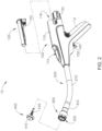
- FIGS. 1-2 depict an exemplary surgical circular stapling instrument (10) that may be used to provide an end-to-end, side-to-side, or end-to-side anastomosis between two sections of an anatomical lumen such as a portion of a patient's digestive tract.
- Instrument (10) of this example comprises a handle assembly (100), a shaft assembly (200), a stapling head assembly (300), and an anvil (400).
- Handle assembly (100) comprises a casing (110) defining an obliquely oriented pistol grip (112).
- pistol grip (112) is perpendicularly oriented.
- pistol grip (112) is omitted.
- Handle assembly (100) further includes a user feedback feature (114) that permits viewing of a movable indicator needle (not shown) as will be described in greater detail below.
- a series of hash marks, colored regions, and/or other fixed indicators are positioned adjacent to user feedback feature (114) in order to provide a visual context for indicator needle.
- Instrument (10) includes a battery pack (120).
- Battery pack (120) is operable to provide electrical power to a motor (160) in pistol grip (112).
- battery pack (120) may be inserted into a socket (116) defined by casing (110). Once battery pack (120) is fully inserted in socket (116), latches (122) of battery pack (120) may resiliently engage interior features of casing (110) to provide a snap fit.
- battery pack (120) and handle assembly (100) may have complementary electrical contacts, pins and sockets, and/or other features that provide paths for electrical communication from battery pack (120) to electrically powered components in handle assembly (100) when battery pack (120) is inserted in socket (116).
- Shaft assembly (200) extends distally from handle assembly (100) and includes a preformed bend.
- the preformed bend is configured to facilitate positioning of stapling head assembly (300) within a patient's colon.
- Various suitable bend angles or radii that may be used will be apparent to those of ordinary skill in the art in view of the teachings herein.
- Stapling head assembly (300) is located at the distal end of shaft assembly (200). As shown in FIGS. 1-2 , anvil (400) is configured to removably couple with shaft assembly (200), adjacent to stapling head assembly (300). Anvil (400) and stapling head assembly (300) are configured to cooperate to manipulate tissue in three ways, including clamping the tissue, cutting the tissue, and stapling the tissue.
- a knob (130) at the proximal end of handle assembly (100) is rotatable relative to casing (110) to provide precise clamping of the tissue between anvil (400) and stapling head assembly (300). When a safety trigger (140) of handle assembly (100) is pivoted away from a firing trigger (150) of handle assembly (100), firing trigger (150) may be actuated to thereby provide cutting and stapling of the tissue.
- anvil (400) includes a head (410) and a shank (420).
- Head (410) includes a proximal surface (412) that defines an annular array of staple forming pockets (414).
- Staple forming pockets (414) are arranged in two concentric annular arrays in the present example. In some other versions, staple forming pockets (414) are arranged in three or more concentric annular arrays. Staple forming pockets (414) are configured to deform staples as the staples are driven into staple forming pockets (414). For instance, each staple forming pocket (414) may deform a generally "U" shaped staple into a "B" shape as is known in the art.
- proximal surface (412) terminates at an inner edge (416), which defines an outer boundary of an annular recess (418) surrounding shank (420).
- Shank (420) defines a bore (422) and includes a pair of pivoting latch members (430) positioned in bore (422).
- each latch member (430) includes a "T" shaped distal end (432), a rounded proximal end (434), and a latch shelf (436) located distal to proximal end (434).
- "T" shaped distal ends (432) secure latch members (430) within bore (422).
- Latch members (430) are positioned within bore (422) such that distal ends (434) are positioned at the proximal ends of lateral openings (424), which are formed through the sidewall of shank (420).
- Lateral openings (424) thus provide clearance for distal ends (434) and latch shelves (436) to deflect radially outwardly from the longitudinal axis defined by shank (420).
- latch members (430) are configured to resiliently bias distal ends (434) and latch shelves (436) to pivot radially inwardly toward the longitudinal axis defined by shank (420). Latch members (430) thus act as retaining clips. This allows anvil (400) to be removably secured to a trocar (330) of stapling head assembly (300) as will be described in greater detail below.
- anvil (400) may be removably secured to a trocar (330) using any other suitable components, features, or techniques. As shown in FIG. 4 , anvil (400) of the present example includes a breakable washer (417) within annular recess (418). This washer (417) is broken by knife member (340) when the knife member (340) completes a full distal range of motion.
- shank (420) of the present example includes a set of longitudinally extending splines (426) that are spaced about shank (420) in an angular array.
- the proximal end of each spline (426) includes a respective lead-in edge (428).
- splines (426) are configured to engage corresponding splines (316) of an inner body member (310) of stapling head assembly (300) in order to consistently provide a predetermined angular alignment between anvil (400) and stapling head assembly (300).
- this angular alignment may ensure that staple forming pockets (414) of anvil (400) are consistently angularly aligned appropriately with staple openings (324) of stapling head assembly (300).
- splines (426) are precisely and consistently positioned in relation to staple forming pockets (414).
- the machine or other device that is used to join head (410) and shank (420) together may have appropriate indexing capabilities in order to reliably and consistently achieve the proper angular positioning of head (410) and shank (420) to thereby provide precise and consistent positioning of splines (426) in relation to staple forming pockets (414).
- head (410) and shank (420) are formed together simultaneously, as a single unitary construction.
- stapling head assembly (300) of the present example is coupled to a distal end of shaft assembly (200) and comprises a body member (310) and a slidable staple driver member (not shown).
- Body member (310) includes a distally extending cylindraceous inner core member (312).
- Body member (310) is fixedly secured to an outer sheath (210) of shaft assembly (200).
- Body member (310) and outer sheath (210) thus serve together as a mechanical ground for stapling head assembly (300).
- inner core member (312) of body member (310) defines a bore (314).
- a plurality of longitudinally extending splines (316) are equidistantly spaced in an angular array within bore (314).
- the distal ends of splines (316) include lead-in edges (318) that are configured to complement lead-in edges (428) of splines (426) on shank (420) of anvil (400).
- lead-in edges (318, 428) may cooperatively engage each other to drive anvil (400) to rotate relative to trocar (330) to angularly align splines (426) of anvil (400) with the gaps between splines (316) of body member (310).
- the gaps between splines (316) may be configured to have a width that is substantially equal to the width of splines (426).
- anvil (400) may achieve a predetermined angular alignment relative to stapling head assembly (300). This predetermined angular alignment may ensure that staple openings (324) of deck member (320) are precisely aligned with corresponding staple forming pockets (414) of anvil (400).
- splines (316, 426) are configured to cooperate with each other to ensure that staples ejected through staple openings (324) are accurately driven into corresponding staple forming pockets (414, 510, 530) on a consistent basis, regardless of the angular orientation of anvil (400) relative to stapling head assembly (300) at the time anvil (400) is initially secured to trocar (330).
- Trocar (330) is positioned coaxially within inner core member (312) of body member (310).
- Trocar (330) includes a colored region (333).
- trocar (330) is operable to translate distally and proximally relative to body member (310) in response to rotation of knob (130) relative to casing (110) of handle assembly (100).
- Trocar (330) comprises a shaft (332) and a head (334).
- Head (334) includes a pointed tip (336) and an inwardly extending proximal surface (338).
- Shaft (332) thus provides a reduced outer diameter just proximal to head (334), with surface (338) providing a transition between that reduced outer diameter of shaft (332) and the outer diameter of head (334).
- Knife member (340) includes a distally presented, sharp circular cutting edge (342). Knife member (340) also defines an opening that is configured to coaxially receive core member (312) of body member (310).
- a deck member (320) is fixedly secured to body member (310).
- Deck member (320) includes a distally presented deck surface (322) defining two concentric annular arrays of staple openings (324).
- Staple openings (324) are arranged to correspond with the arrangement of staple drivers and staple forming pockets (414) described above.
- each staple opening (324) is configured to provide a path for a corresponding staple driver to drive a corresponding staple through deck member (320) and into a corresponding staple forming pocket (414) when stapling head assembly (300) is actuated.
- the arrangement of staple openings (322) may be modified just like the arrangement of staple forming pockets (414) as described above.
- deck member (320) defines an inner diameter that is just slightly larger than the outer diameter defined by knife member (340). Deck member (320) is thus configured to allow knife member (340) to translate distally to a point where cutting edge (342) is distal to deck surface (322).
- anvils 500, 600, 700
- surgical instrument (10) includes anvil (500, 600, 700), that is intended to be used in place of anvil (400) described above with reference to FIGS. 1-5 .
- surgical instrument (10) includes a body (shown as handle assembly (100)), shaft assembly (200) extending distally from handle assembly (100), stapling head assembly (300), and anvil (400).
- Stapling head assembly (300) is positioned at a distal end of shaft assembly (200).
- Stapling head assembly (300) includes an anvil coupling feature (shown as trocar (330)), at least one annular array of staples, and the staple driver.
- anvils (500, 600, 700) are each configured to couple with trocar (330) and each are configured to deform staples driven by the staple driver.
- FIGS. 9-12 show various perspective views of a first exemplary anvil (500) that may be incorporated into instrument (10) of FIG. 1 .
- Anvil (500) includes a head (510) and a shank (520).
- Shank (520) extends proximally from head (510) and is configured to be coupled with head (510) once formed.
- Head (510) includes a proximal surface (512) that defines an annular array of staple forming pockets (514) shown in FIG. 10 .
- staple forming pockets (514) are arranged in two concentric annular arrays, similar to those shown in FIG. 16 .
- staple forming pockets (514b) may be arranged in three or more concentric annular arrays, similar to those shown in FIG. 17 .
- Staple forming pockets (514) are configured to deform the staples as the staples are driven into staple forming pockets (514).
- each staple forming pocket (514) may deform a generally "U” shaped staple into a "B" shape as is known in the art.
- proximal surface (512) of head (510) terminates at an inner edge (516), which defines an outer boundary of an annular recess (518) surrounding shank (520).
- head (510), including staple forming pockets (514) may be formed using an injection molding process, such as a metal injection molding process.
- Metal injection molding refers to any metalworking process where finely-powdered metal is mixed with a binder material to create a feedstock that is subsequently shaped and solidified using molding process (such as injection molding). Metal injection molding allows for high volume, complex parts to be shaped.
- head (510) may be formed from a polymeric material using an injection molding process.
- at least a portion of at least one staple forming pocket (514) may be coined or electrochemically machined to improve one or more properties of staple forming pockets (514).
- Shank (520) includes a longitudinally extending body (521) that defines a bore (522) and may include a pair of pivoting latch members (not shown) positioned in bore (522), that may be similar in structure and function to latch members (430) described above with reference to shank (420) of anvil (400).
- the latch members are positioned within bore (522) such that the distal ends are positioned at the proximal ends of lateral openings (524), which are formed through the sidewall of shank (520). Lateral openings (524) provide clearance for the latch member to deflect radially outwardly from the longitudinal axis defined by shank (520).
- the latch members allow anvil (500) to be removably secured to a trocar (330) of stapling head assembly (300).
- shank (520) is secured to trocar (330) and trocar (330) is retracted proximally, the inner diameter of bore (314) in inner core member (312) of body member (310) laterally constrains the latch members to maintain engagement with proximal surface (338) of head (334) of trocar (330). This engagement prevents anvil (500) from being released from trocar (330) during firing of stapling head assembly (300).
- the latch members may be omitted, such that anvil (500) may be removably secured to a trocar (330) using any other suitable components, features, or techniques.
- shank (520) includes a set of longitudinally extending splines (526) that are spaced about shank (520) in an angular array.
- the proximal end of each spline (526) includes a respective lead-in edge (528).
- Splines (526) are configured to engage corresponding splines (316) of an inner body member (310) of stapling head assembly (300) to consistently provide a predetermined angular alignment between anvil (500) and stapling head assembly (300). This angular alignment may ensure that staple forming pockets (514) of anvil (500) are consistently angularly aligned appropriately with staple openings (324) of stapling head assembly (300).
- shank (520) further includes a flange (540) extending radially outward from a distal end (542) of shank (520).
- flange (540) has a larger area than longitudinally extending body (521) of shank (520).
- Flange (540) includes opposing proximal and distal surfaces (544, 546).
- shank (520) may be machined using one or more machining processes.
- head (510) includes a recessed portion (548) that extends proximally from a distal outer surface (550).
- Recessed portion (548) includes a recessed surface (552) surrounded by an annular wall (554), with an aperture (556) extending through recessed surface (552) that is configured to receive longitudinally extending body (521) of shank (520).
- aperture (556) is concentric to both distal outer surface (550) and recessed surface (552); however, other positionings of aperture (556) relative to distal outer surface (550) and recessed surface (552) are also envisioned.
- recessed portion (548) is sized and configured to receive flange (540) of shank (520).
- recessed portion (548) and flange (540) are shown as circular, it is also envisioned that recessed portion (548) and flange (540) may have a variety of other shapes (e.g. rectangular) that may prevent relative rotation of head (510) and shank (520), if desired.
- Distal outer surface (555) also includes one or more recesses (558), with two being shown, which may be used to secure a distal feature (such as a cap).
- Head (510) may also include a tapered portion (560) extending proximally from distal outer surface (550). Tapered portion (560) is shown as a chamfer.
- Recessed surface (552) of recessed portion (548) may be in direct contact with proximal surface (544) of flange (520) once head (510) is coupled with shank (520).
- distal outer surface (550) of head (510) is generally flush with distal surface of flange (540) after head (510) is coupled with shank (520).
- the depth of recessed portion (548) is about the same as the thickness of flange (540). However, the depth of recessed portion (548) and/or the thickness of flange (540) may vary. Additionally, distal outer surface (550) may be arcuate, if desired.
- head (510) may be coupled to shank (520) using a cap (562), shown as a thin anvil plate.
- Cap (562) is configured to sandwich flange (540) of shank (520) between cap (562) and head (510).
- Cap (562) includes proximal and distal surfaces (564, 566).
- the cap (562) may be of polymeric material.
- a cap (562) is overmolded onto head (510) using one or more overmolding processes. More specifically, cap (562) may be overmolded onto distal surface (546) of flange (540) and/or distal outer surface (550) of head (510). As a result, cap (562) may not be a separate component.
- cap (562) may be selectively coupleable to head (510) using one or more securement features that are configured to couple with recess (558).
- cap (562) is formed from a polymeric material; however, cap (562) may be formed from any suitable material.
- Staple forming pockets (514) may be formed simultaneously with or after head (510) is formed.
- FIGS. 11 and 12 show perspective views of head (510), but with staple forming pockets (514) not yet formed.
- head (510) may be machined after forming head (510) if desired.
- staple forming pocket (514) may be coined or electrochemical machined after forming staple forming pocket (514) using an injection molding process (e.g. a metal injection molding process). More specifically, FIG. 13A shows a staple forming pocket (514a) prior to being coined or electrochemically machined, while FIG. 13B shows the staple forming pocket (514) of FIG. 13A , after being coined or electrochemically machined. As shown in FIG. 13A , staple forming pocket (514a) includes a central portion (570a) disposed between outer portions (572a, 574a). As shown in FIGS.
- central portion (570) of staple forming pocket (514) is subsequently coined or electrochemically machined, which results in a smoother surface and a denser surface than another portion (e.g. outer portions (572, 574)) that was not coined or electrochemical machined.
- outer portions (572, 574) have surface that is rougher and less dense than central portion (570) of staple forming pocket (514).
- the entire staple forming pocket (514), including outer portions (572, 574), may be coined or electrochemically machined, if desired.
- Coining is a form of precision stamping where a workpiece is subjected to a sufficiently high stress to induce plastic flow on the surface of the material.
- the plastic flow reduces surface grain size and work hardens the surface of the workpiece, while the material deeper within the workpiece retains its toughness and ductility.
- Coining also improves the dimensional tolerances of staple forming pocket (514).
- Electrochemical machining is a method of removing metal using one or more electrochemical processes. Electrochemical machining may be used for mass production due to cost effectiveness and is utilized for working extremely hard materials or materials that are difficult to machine using conventional methods. Electrochemical machining may cut small or uniquely-shaped angles, intricate contours, or cavities in hard metals workpieces.
- FIG. 14A shows central portion (570a) of staple forming pocket (514a) taken along line 14A-14A of FIG. 13A
- FIG. 14B shows central portion (570) of staple forming pocket (514), taken along line 14B-14B of FIG. 13B
- central portion (570a) having been coined or electrochemically machined is both smoother and denser than another portion (e.g. outer portions (572, 574)) of the same staple forming pocket (514) that was not coined or electrochemically machined.
- FIG. 15A shows a portion of staple forming pocket (514a) of FIG. 13A , taken along line 15A-15A
- FIG. 15B shows a portion of staple forming pocket (514) of FIG. 13B , taken along line 15B-15B.
- a channel (576) results after the coining or electrochemical machining process.
- FIG. 16 shows an annular array of staple forming pockets (514) of FIG. 13B , after being coined or electrochemically machined. More specifically, central portions (570) are coined or electrochemically machined.
- FIG. 17 shows another an annular array of staple forming pockets (514b) after being coined or electrochemically machined. Similar to staple forming pockets (514), staple forming pockets (514b) also include a central portion (570b) and outer portions (572b, 574b). As shown, a central portion (570b) is coined or electrochemically machined, and as a result, is both smoother and denser than another portion (e.g. outer portions (572b, 574b)) of same staple forming pocket (514b) that is not coined or electrochemically machined.
- a central portion (570b) is coined or electrochemically machined, and as a result, is both smoother and denser than another portion (e.g. outer portions (572b, 574b)) of same staple forming pocket (514b) that is not coined or electrochemically machined.
- FIG. 18 shows a perspective view of a second exemplary anvil (600) that may be incorporated into instrument (10) of FIG. 1 in place of anvil (400, 500) described above.
- anvil (600) includes a head (610), a shank (620), and a cap (662).
- cap (662) includes one or more engagement features.
- head (610) includes a proximal surface (612), staple forming pockets (614), a recessed portion (648), a distal outer surface (650), a recessed surface (652), an annular wall (654), an aperture (656), recesses (658), and a tapered portion (660).
- shank (620) includes a bore (622), lateral openings (624), a set of longitudinally extending splines (626), lead-in edges (628), a flange (640), and a distal end (642). Similar to flange (540), flange (640) includes opposing proximal and distal surfaces (644, 646). Similar to cap (562), cap (662) includes opposing proximal distal surfaces (664, 666).
- Proximal surface (612) of head (610) defines an annular array of staple forming pockets (614), which are similar to those shown in FIG. 10 .
- head (610), including staple forming pockets (614) may be formed using a metal injection molding process and subsequently machined using one or more machining processes.
- at least a portion of at least one staple forming pocket (614) may be coined or electrochemically machined to improve one or more properties of staple forming pockets (614).
- Recessed portion (648) of head (610) extends proximally from distal outer surface (650).
- Recessed surface (652) is surrounded by annular wall (654), with aperture (656) extending through recessed surface (652).
- Aperture (656) is configured to receive longitudinally extending body (621) of shank (620) therethrough.
- Recessed portion (648) is sized and configured to receive flange (640) of shank (620).
- Recessed portion (648) of head (610) may be in direct contact with proximal surface (644) of flange (620), once head (610) is coupled with shank (620).
- Distal outer surface (655) of head (610) also includes one or more recesses (658), with two being shown, which may be used to secure a distal feature, such as cap (662).
- Tapered portion (660) extends proximally from distal outer surface (650).
- shank (620) extends proximally from head (610) and is configured to be coupled with head (610) once formed. While not shown in FIGS. 8-12 , shank (620) includes an outwardly extending portion (630). As shown in FIG. 18 , flange (640) extending radially outward from distal end (642) of shank (620). Flange (640) includes opposing proximal and distal surfaces (644, 646). As described in greater detail with reference to FIG. 20 , shank (620) may be formed using a metal injection molding process and subsequently machined using one or more machining processes. As a result, both head (610) and shank (620) may be separately formed using metal injection molding processes. Additionally, both head (610) and shank (620) may be separately machined after being formed from the respective metal injection molding processes.
- Head (610) may be coupled to shank (620) using cap (662), shown in this exemplary embodiment as an arcuate cap.
- Cap (662) is configured to sandwich flange (640) of shank (620) between cap (662) and head (610).
- cap (662) is selectively couplable to head (610) using one or more securement features.
- cap (662) may include at least one proximally facing projection (668), that is configured to couple with at least one corresponding recess (658).
- coupling cap (662) with head (610) includes inserting proximally facing projections (668) into recesses (658).
- each recess (662) is shown as extending completely through distal outer surface (650), it is envisioned that recesses (658) may extend only partly through distal outer surface (650).
- cap (662) is shown as being formed from a polymeric material; it is envisioned that cap (662) may be formed from any suitable material. As shown, distal surface (666) of cap (662) is rounded, forming a hemispherical shape.
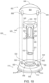
- FIG. 19 shows a perspective view of a third exemplary anvil (700) that may be incorporated into instrument (10) of FIG. 1 in place of anvil (400, 500) described above.
- anvil (700) includes a head (710) and a shank (720).
- head (710) includes a proximal surface (712), staple forming pockets (714), a recessed portion (748), a distal outer surface (750), a recessed surface (752), an annular wall (754), an aperture (756), and a tapered portion (760).
- shank (720) includes a bore (722), lateral openings (724), a set of longitudinally extending splines (726), lead-in edges (728), and a flange (740) and a distal end (742). Similar to flange (540), flange (740) includes opposing proximal and distal surfaces (744, 746).
- Proximal surface (712) of head (710) defines an annular array of staple forming pockets (714), which are similar to those shown in FIG. 10 .
- head (710) including staple forming pockets (714), may be formed using a metal injection molding process and subsequently machined using one or more machining processes.
- staple forming pocket (514) in FIGS. 13A-16 at least a portion of at least one staple forming pocket (714) may be coined or electrochemically machined to improve one or more properties of staple forming pockets (714).
- Recessed portion (748) of head (710) extends proximally from distal outer surface (750).
- Recessed surface (752) is surrounded by annular wall (754), with aperture (756) extending through recessed surface (752). Aperture (756) is configured to receive longitudinally extending body (721) of shank (720) therethrough.
- Recessed portion (748) is sized and configured to receive flange (740) of shank (720). Recessed surface (752) of recessed portion (748) may be in direct contact with proximal surface (744) of flange (720), once head (710) is coupled with shank (720).
- Tapered portion (760) extends proximally from distal outer surface (750).
- shank (720) extends proximally from head (710) and is configured to be coupled with head (710) once formed. While not shown in FIGS. 8-12 , shank (720) includes an outwardly extending portion (730). As shown in FIG. 19 , flange (740) extend radially outward from distal end (742) of shank (720). Flange (740) includes opposing proximal and distal surfaces (744, 746). Distal surface (746) of flange (740) includes an inner shallow portion (762) and a rounded outer edge portion (764). As shown, rounded outer edge portion (764) includes a distal most portion (766) that is the distal most point of shank (720). A proximal surface (744) of flange (740) is coupled with distal outer surface (750) of head (710). Shank (720) may be formed using a metal injection molding process and subsequently machined using one or more machining processes.
- head (510, 610, 710) may be formed using a metal injection molding process using a metal injection molding machine.
- method (800) includes machining at least a portion of head (510, 610, 710). Machining may include coining or electrochemical machining at least a portion of at least one staple forming pocket (514, 614, 714) using a stamping or ECM machine (814). As previously described, the portion of staple forming pocket (514, 614, 714) coined or electrochemically machined is both smoother and denser than another portion that was not coined or electrochemical machined. Other benefits may also be achieved.
- method (800) includes forming shank (520, 620, 720) using an injection molding machine (816).
- Injection molding machine (816) may be the same or different than injection molding machine (812).
- Shank (520, 620, 720) may be formed using a metal injection molding process using a metal injection molding machine.
- method (800) includes machining shank (520, 620, 720) using a lathe (818). If desired, shank (520, 620, 720) may be machined from a single piece of material without be previously formed using an injection molding process.
- method (800) includes coupling head (510, 610, 710) with shank (520, 620, 720) that were separately manufactured.
- Coupling head (510, 610) with shank (520, 620) may include coupling cap (562, 662) with head (510, 610) to sandwich flange (540, 640) of shank (520, 620) between cap (562, 662) and head (510, 610). More specifically, where cap (662) includes proximally facing projections (668), coupling cap (662) with head (610) includes inserting proximally facing projections (668) into recesses (658) of head (610).
- coupling head (510, 610, 710) with shank (520, 620, 720) may include, for example, one or more overmolding, welds, adhesive, and/or mechanical securement features (e.g. projections (668)).
- staples formed by anvil (400, 500, 600, 700) will have a three-dimensional profile, where the legs are angularly offset from a plane passing through a crown of the staple; in addition to being bent generally toward each other.
- the staples formed using anvil (400, 500, 600, 700) may have an appearance similar to at least some of the staples shown and described in U.S. Pub. No. 2014/0239037, entitled “Staple Forming Features for Surgical Stapling Instrument," published August 28, 2014 , now U.S. Pat. No. 10, 092, 292, issued on October 9, 2018 .
- the staples formed using anvil may have an appearance similar to at least some of the staples shown and described in U.S. Pat. Pub. No. 2018/0132849, entitled “Staple Forming Pocket Configurations for Circular Surgical Stapler Anvil,” published May 17, 2018 . Additional features of anvils are disclosed in U.S. Pub. No. 2017/0258471 published September 14, 2017 ; U.S. Pub. No. 2015/0083772 published March 26, 2015 , now abandoned; U.S. Pub. No. 2015/0083774 published March 26, 2015 , now U.S. Pat. No. 9,907,552, issued March 6, 2018 ; U.S. Pub. No.
- anvil 400, 500, 600, 700
- anvil may be further constructed and operable in accordance with at least some of the teachings of U.S. Pat. No. 5,205,459 ; U.S. Pat. No. 5,271,544 ; U.S. Pat. No. 5,275,322 ; U.S. Pat. No. 5,285,945 ; U.S. Pat. No. 5,292,053 ; U.S. Pat. No. 5,333,773 ; U.S. Pat. No. 5,350,104 ; U.S. Pat. No. 5,533,661 ; and/or U.S. Pat. No. 8,910,847 . Still other suitable configurations will be apparent to one of ordinary skill in the art in view of the teachings herein.
- teachings herein may also be readily combined with one or more teachings of U.S. Pub. No. 2017/0258471, entitled “Methods and Systems for Performing Circular Stapling," published September 14, 2017 .
- Other suitable kinds of instruments in which the teachings herein may be applied, and various ways in which the teachings herein may be applied to such instruments, will be apparent to those of ordinary skill in the art.
- Versions of the devices described above may have application in conventional medical treatments and procedures conducted by a medical professional, as well as application in robotic-assisted medical treatments and procedures.
- various teachings herein may be readily incorporated into a robotic surgical system such as the DAVINCI TM system by Intuitive Surgical, Inc., of Sunnyvale, California.
- Versions described above may be designed to be disposed of after a single use, or they can be designed to be used multiple times. Versions may, in either or both cases, be reconditioned for reuse after at least one use. Reconditioning may include any combination of the steps of disassembly of the device, followed by cleaning or replacement of particular pieces, and subsequent reassembly. In particular, some versions of the device may be disassembled, and any number of the particular pieces or parts of the device may be selectively replaced or removed in any combination. Upon cleaning and/or replacement of particular parts, some versions of the device may be reassembled for subsequent use either at a reconditioning facility, or by a user immediately prior to a procedure.
- reconditioning of a device may utilize a variety of techniques for disassembly, cleaning/replacement, and reassembly. Use of such techniques, and the resulting reconditioned device, are all within the scope of the present application.
- versions described herein may be sterilized before and/or after a procedure.
- the device is placed in a closed and sealed container, such as a plastic or TYVEK bag.
- the container and device may then be placed in a field of radiation that can penetrate the container, such as gamma radiation, x-rays, or high-energy electrons.
- the radiation may kill bacteria on the device and in the container.
- the sterilized device may then be stored in the sterile container for later use.
- a device may also be sterilized using any other technique known in the art, including but not limited to beta or gamma radiation, ethylene oxide, or steam.
Landscapes
- Health & Medical Sciences (AREA)
- Surgery (AREA)
- Life Sciences & Earth Sciences (AREA)
- Engineering & Computer Science (AREA)
- Heart & Thoracic Surgery (AREA)
- Biomedical Technology (AREA)
- Nuclear Medicine, Radiotherapy & Molecular Imaging (AREA)
- Medical Informatics (AREA)
- Molecular Biology (AREA)
- Animal Behavior & Ethology (AREA)
- General Health & Medical Sciences (AREA)
- Public Health (AREA)
- Veterinary Medicine (AREA)
- Mechanical Engineering (AREA)
- Surgical Instruments (AREA)
Claims (13)
- Verfahren zum Herstellen eines Ambosses eines chirurgischen Rundklammergeräts, wobei der Amboss (500) einen Kopf (510) und einen Schaft (520) einschließt, der sich von dem Kopf proximal erstreckt, wobei der Schaft einen Flansch (540) einschließt, der sich von einem distalen Ende des Schafts radial nach außen erstreckt, das Verfahren umfassend:(a) Ausbilden des Kopfes (510) eines chirurgischen Rundklammergeräts unter Verwendung eines Metallspritzgussprozesses;(b) Ausbilden einer ringförmigen Anordnung von Klammerausbildungstaschen (514) in dem Kopf (510);(c) Bearbeiten des Schafts (520) des chirurgischen Rundklammergeräts; und(d) Koppeln des Kopfes (510) und des Schafts (520) des chirurgischen Rundklammergeräts, die getrennt hergestellt wurden, durch ein Aufspritzen einer Kappe auf den Kopf des Ambosses, um den Flansch des Schafts zwischen der Kappe und dem Kopf sandwichartig zu umschließen.
- Verfahren nach Anspruch 1, ferner umfassend:
Ausbilden des Schafts unter Verwendung eines Metallspritzgussprozesses vor dem Bearbeiten des Schafts. - Verfahren nach Anspruch 1, ferner umfassend:
Bearbeiten von mindestens einem Abschnitt des Kopfes nach dem Ausbilden des Kopfes unter Verwendung des Metallspritzgussprozesses. - Verfahren nach Anspruch 1, wobei das Ausbilden des Kopfes unter Verwendung des Metallspritzgussprozesses und das Ausbilden der ringförmigen Anordnung von Klammerausbildungstaschen in dem Kopf gleichzeitig durchgeführt werden.
- Verfahren nach Anspruch 1, wobei das Ausbilden des Kopfes unter Verwendung des Metallspritzgussprozesses vor dem Ausbilden der ringförmigen Anordnung von Klammerausbildungstaschen in dem Kopf erfolgt.
- Verfahren nach Anspruch 1, wobei das Verfahren nach dem Ausbilden der ringförmigen Anordnung von Klammerausbildungstaschen unter Verwendung des Metallspritzgussprozesses ferner ein Prägen oder ein elektrochemisches Bearbeiten von mindestens einem Abschnitt von mindestens einer Klammerausbildungstasche der ringförmigen Anordnung von Klammerausbildungstaschen umfasst.
- Verfahren nach Anspruch 6, wobei der geprägte oder elektrochemisch bearbeitete Abschnitt sowohl glatter als auch dichter als ein anderer Abschnitt ist, der nicht geprägt oder elektrochemisch bearbeitet wurde.
- Verfahren nach Anspruch 7, wobei der geprägte oder elektrochemisch bearbeitete Abschnitt ein zentraler Abschnitt von mindestens einer Klammerausbildungstasche der ringförmigen Anordnung von Klammerausbildungstaschen ist.
- Verfahren nach Anspruch 1, wobei das Ausbilden des Kopfes ferner das Ausbilden des Kopfes umfasst, um eine distale Außenoberfläche (550) und einen distalen vertieften Abschnitt (548) einzuschließen, der proximal zu der distalen Außenoberfläche angeordnet ist, wobei der distale vertiefte Abschnitt bemessen und konfiguriert ist, um den Flansch des Schafts aufzunehmen.
- Verfahren nach Anspruch 9, wobei der Flansch gegenüberliegende proximale und distale Oberflächen (544, 546) einschließt, wobei das Koppeln des Kopfes mit dem Schaft ferner ein Berühren der proximalen Oberfläche des Flansches mit dem distalen vertieften Abschnitt des Kopfes umfasst.
- Verfahren nach Anspruch 10, wobei das Berühren der proximalen Oberfläche des Flansches mit dem distalen vertieften Abschnitt des Kopfes ferner das Berühren der proximalen Oberfläche des Flansches mit dem distalen vertieften Abschnitt des Kopfes derart umfasst, dass die distale Außenoberfläche des Kopfes im Allgemeinen bündig mit der distalen Oberfläche des Flansches ist.
- Verfahren nach Anspruch 1, wobei der Flansch einen inneren flachen Abschnitt und einen abgerundeten äußeren Randabschnitt umfasst, wobei das Koppeln des Kopfes mit dem Schaft ferner das Koppeln einer proximalen Oberfläche des Flansches mit einer distalen Oberfläche des Kopfes umfasst.
- Amboss eines chirurgischen Rundklammergeräts, erhältlich durch das Verfahren nach Anspruch 1.
Applications Claiming Priority (1)
| Application Number | Priority Date | Filing Date | Title |
|---|---|---|---|
| US16/236,700 US11291450B2 (en) | 2018-12-31 | 2018-12-31 | Anvil for circular surgical stapler and associated method of manufacture with MIM |
Publications (4)
| Publication Number | Publication Date |
|---|---|
| EP3673835A2 EP3673835A2 (de) | 2020-07-01 |
| EP3673835A3 EP3673835A3 (de) | 2020-09-09 |
| EP3673835C0 EP3673835C0 (de) | 2025-02-26 |
| EP3673835B1 true EP3673835B1 (de) | 2025-02-26 |
Family
ID=69055827
Family Applications (1)
| Application Number | Title | Priority Date | Filing Date |
|---|---|---|---|
| EP19219993.3A Active EP3673835B1 (de) | 2018-12-31 | 2019-12-30 | Amboss für kreisförmiges chirurgisches klammergerät und zugehöriges herstellungsverfahren mit mim |
Country Status (6)
| Country | Link |
|---|---|
| US (2) | US11291450B2 (de) |
| EP (1) | EP3673835B1 (de) |
| JP (1) | JP7494183B2 (de) |
| CN (1) | CN113260322B (de) |
| BR (1) | BR112021012566A2 (de) |
| WO (1) | WO2020141381A1 (de) |
Families Citing this family (13)
| Publication number | Priority date | Publication date | Assignee | Title |
|---|---|---|---|---|
| US11291450B2 (en) | 2018-12-31 | 2022-04-05 | Cilag Gmbh International | Anvil for circular surgical stapler and associated method of manufacture with MIM |
| US11911039B2 (en) | 2021-08-13 | 2024-02-27 | Cilag Gmbh International | Circular surgical stapler having staples with expandable crowns |
| US11998209B2 (en) | 2021-08-13 | 2024-06-04 | Cilag Gmbh International | Staple forming features for circular surgical stapler |
| US11944310B2 (en) | 2021-08-13 | 2024-04-02 | Cilag Gmbh International | Non-circular end effector features for surgical stapler |
| US12256934B2 (en) | 2021-08-13 | 2025-03-25 | Cilag Gmbh International | Methods of forming an anastomosis between organs with an expandable pattern |
| US12201301B2 (en) | 2021-08-13 | 2025-01-21 | Cilag Gmbh International | Circular surgical stapler end effector having staple line alignment feature |
| US11666339B2 (en) * | 2021-08-13 | 2023-06-06 | Cilag Gmbh International | Circular surgical stapler for forming cross-pattern of staples |
| US11653926B2 (en) | 2021-08-13 | 2023-05-23 | Cilag Gmbh International | Circular surgical stapler for forming pattern of non-tangential staples |
| US12004744B2 (en) | 2021-09-27 | 2024-06-11 | Cilag Gmbh International | Staple and staple-forming pocket arrangements for surgical staplers |
| US12453553B2 (en) | 2021-09-27 | 2025-10-28 | Cilag Gmbh International | Overlapping staple pattern for surgical stapler |
| US11992218B2 (en) | 2021-10-18 | 2024-05-28 | Cilag Gmbh International | Metal injection molded anvil for circular surgical stapler |
| CN116329516A (zh) * | 2023-03-23 | 2023-06-27 | 安徽昊方机电股份有限公司 | 抵钉座及制作方法 |
| WO2024228981A1 (en) * | 2023-05-01 | 2024-11-07 | Intuitive Surgical Operations, Inc. | Components of surgical stapling instruments and methods for manufacturing the same |
Family Cites Families (168)
| Publication number | Priority date | Publication date | Assignee | Title |
|---|---|---|---|---|
| US4184620A (en) * | 1977-08-01 | 1980-01-22 | Parker Manufacturing Company | Spring powered stapler |
| US4119258A (en) * | 1977-08-01 | 1978-10-10 | Parker Manufacturing Company | Plastic staple gun |
| US4224267A (en) * | 1978-03-28 | 1980-09-23 | Westinghouse Electric Corp. | Wire, rod, stick, and the like, with or without fluxing agent for welding applications |
| JPS62136383A (ja) * | 1985-11-21 | 1987-06-19 | 海老原 代師行 | ステ−プラ |
| US5366459A (en) | 1987-05-14 | 1994-11-22 | Inbae Yoon | Surgical clip and clip application procedures |
| US5285944A (en) * | 1987-05-26 | 1994-02-15 | United States Surgical Corporation | Surgical stapler apparatus |
| US4813143A (en) * | 1987-06-25 | 1989-03-21 | Alcas Cutlery Corporation | Handle and knives comprising the same |
| US5104025A (en) * | 1990-09-28 | 1992-04-14 | Ethicon, Inc. | Intraluminal anastomotic surgical stapler with detached anvil |
| GR920100358A (el) | 1991-08-23 | 1993-06-07 | Ethicon Inc | Οργανο συρραφής χειρουργικής αναστομώσεως. |
| US5333773A (en) | 1991-08-23 | 1994-08-02 | Ethicon, Inc. | Sealing means for endoscopic surgical anastomosis stapling instrument |
| US5350104A (en) | 1991-08-23 | 1994-09-27 | Ethicon, Inc. | Sealing means for endoscopic surgical anastomosis stapling instrument |
| US5364001A (en) * | 1991-10-18 | 1994-11-15 | United States Surgical Corporation | Self contained gas powered surgical apparatus |
| AU657364B2 (en) * | 1991-10-18 | 1995-03-09 | United States Surgical Corporation | Self contained gas powered surgical apparatus |
| US5163945A (en) | 1991-10-18 | 1992-11-17 | Ethicon, Inc. | Surgical clip applier |
| US5308576A (en) * | 1991-10-18 | 1994-05-03 | United States Surgical Corporation | Injection molded anvils |
| US5297746A (en) * | 1992-02-06 | 1994-03-29 | Nelmor Company, Inc. | Granulator knife |
| US5271543A (en) * | 1992-02-07 | 1993-12-21 | Ethicon, Inc. | Surgical anastomosis stapling instrument with flexible support shaft and anvil adjusting mechanism |
| US5342373A (en) | 1992-09-14 | 1994-08-30 | Ethicon, Inc. | Sterile clips and instrument for their placement |
| US5411514A (en) * | 1992-09-30 | 1995-05-02 | Linvatec Corporation | Bendable variable angle rotating shaver |
| US5403312A (en) | 1993-07-22 | 1995-04-04 | Ethicon, Inc. | Electrosurgical hemostatic device |
| US5431668A (en) | 1993-04-29 | 1995-07-11 | Ethicon, Inc. | Ligating clip applier |
| US5409276A (en) * | 1993-06-23 | 1995-04-25 | Engasser; George L. | Readily releasable hasp and staple |
| US5487499A (en) * | 1993-10-08 | 1996-01-30 | United States Surgical Corporation | Surgical apparatus for applying surgical fasteners including a counter |
| US7043819B1 (en) * | 1996-12-23 | 2006-05-16 | Recast Airfoil Group | Methods for forming metal parts having superior surface characteristics |
| CA2143560C (en) | 1994-03-02 | 2007-01-16 | Mark Fogelberg | Sterile occlusion fasteners and instrument and method for their placement |
| US5584845A (en) * | 1994-08-18 | 1996-12-17 | Innovasive Devices, Inc. | Surgical scissor blade and method for making the same |
| US5480089A (en) * | 1994-08-19 | 1996-01-02 | United States Surgical Corporation | Surgical stapler apparatus with improved staple pockets |
| JPH08289895A (ja) * | 1995-04-21 | 1996-11-05 | Olympus Optical Co Ltd | 縫合器 |
| US5722306A (en) * | 1995-06-07 | 1998-03-03 | Alloy Technology International Inc. | Method for making a pelletizer knife and blank |
| US5807338A (en) * | 1995-10-20 | 1998-09-15 | United States Surgical Corporation | Modular trocar system and methods of assembly |
| US6269714B1 (en) * | 1996-05-30 | 2001-08-07 | Kakoh Kiki Co., Ltd. | Cutter knife for thermoplastic resin pelletizer and production method of said cutter knife |
| US6176021B1 (en) * | 1997-03-12 | 2001-01-23 | Mitutoyo Corporation | Micrometer |
| US6050996A (en) * | 1997-11-12 | 2000-04-18 | Sherwood Services Ag | Bipolar electrosurgical instrument with replaceable electrodes |
| US5951574A (en) | 1998-10-23 | 1999-09-14 | Ethicon Endo-Surgery, Inc. | Multiple clip applier having a split feeding mechanism |
| US6142933A (en) * | 1998-11-23 | 2000-11-07 | Ethicon Endo-Surgery, Inc. | Anoscope for hemorrhoidal surgery |
| US8025199B2 (en) * | 2004-02-23 | 2011-09-27 | Tyco Healthcare Group Lp | Surgical cutting and stapling device |
| US6185771B1 (en) * | 1999-12-06 | 2001-02-13 | John E. Trusty, Sr. | Pocket tool having slidably extensible pliers |
| JP4346439B2 (ja) | 2001-10-05 | 2009-10-21 | タイコ ヘルスケア グループ エルピー | 外科的ファスナーデバイスのための傾斜トップアンビル |
| US9597078B2 (en) * | 2003-04-29 | 2017-03-21 | Covidien Lp | Surgical stapling device with dissecting tip |
| US7380696B2 (en) | 2003-05-20 | 2008-06-03 | Ethicon Endo-Surgery, Inc. | Articulating surgical stapling instrument incorporating a two-piece E-beam firing mechanism |
| US7000818B2 (en) | 2003-05-20 | 2006-02-21 | Ethicon, Endo-Surger, Inc. | Surgical stapling instrument having separate distinct closing and firing systems |
| US7150749B2 (en) * | 2003-06-13 | 2006-12-19 | Sherwood Services Ag | Vessel sealer and divider having elongated knife stroke and safety cutting mechanism |
| JP4755983B2 (ja) * | 2003-07-16 | 2011-08-24 | タイコ ヘルスケア グループ リミテッド パートナーシップ | 組織テンショナーを備えた外科用ステープル留めデバイス |
| US20050149087A1 (en) * | 2003-11-05 | 2005-07-07 | Applied Medical Resources Corporation | Multiple-angle scissor blade |
| US7204404B2 (en) | 2003-12-30 | 2007-04-17 | Ethicon Endo-Surgery, Inc. | Slotted pins guiding knife in a curved cutter stapler |
| US20050145672A1 (en) | 2003-12-30 | 2005-07-07 | Schwemberger Richard F. | Curved cutter stapler with aligned tissue retention feature |
| US6988650B2 (en) | 2003-12-30 | 2006-01-24 | Ethicon Endo-Surgery, Inc. | Retaining pin lever advancement mechanism for a curved cutter stapler |
| US7134587B2 (en) | 2003-12-30 | 2006-11-14 | Ethicon Endo-Surgery, Inc. | Knife retraction arm for a curved cutter stapler |
| US20050139636A1 (en) | 2003-12-30 | 2005-06-30 | Schwemberger Richard F. | Replaceable cartridge module for a surgical stapling and cutting instrument |
| US7207472B2 (en) | 2003-12-30 | 2007-04-24 | Ethicon Endo-Surgery, Inc. | Cartridge with locking knife for a curved cutter stapler |
| US20050143759A1 (en) | 2003-12-30 | 2005-06-30 | Kelly William D. | Curved cutter stapler shaped for male pelvis |
| US7147140B2 (en) | 2003-12-30 | 2006-12-12 | Ethicon Endo - Surgery, Inc. | Cartridge retainer for a curved cutter stapler |
| US8181840B2 (en) * | 2004-03-19 | 2012-05-22 | Tyco Healthcare Group Lp | Tissue tensioner assembly and approximation mechanism for surgical stapling device |
| US9072535B2 (en) | 2011-05-27 | 2015-07-07 | Ethicon Endo-Surgery, Inc. | Surgical stapling instruments with rotatable staple deployment arrangements |
| US20060047309A1 (en) * | 2004-08-25 | 2006-03-02 | Cichocki Frank R Jr | Metal injection molded suture needles |
| US7195631B2 (en) * | 2004-09-09 | 2007-03-27 | Sherwood Services Ag | Forceps with spring loaded end effector assembly |
| US8601907B2 (en) * | 2004-09-24 | 2013-12-10 | Kai U.S.A., Ltd. | Knife blade manufacturing process |
| EP2345375A1 (de) * | 2004-10-18 | 2011-07-20 | Tyco Healthcare Group LP | Ringförmige Klebestruktur |
| EP1804682B1 (de) * | 2004-10-18 | 2017-11-29 | Covidien LP | Struktur zum aufsprühen eines wundbehandlungsmaterials |
| US7328829B2 (en) * | 2004-12-13 | 2008-02-12 | Niti Medical Technologies Ltd. | Palm size surgical stapler for single hand operation |
| US7261724B2 (en) | 2005-04-14 | 2007-08-28 | Ethicon Endo-Surgery, Inc. | Surgical clip advancement mechanism |
| US7731724B2 (en) | 2005-04-14 | 2010-06-08 | Ethicon Endo-Surgery, Inc. | Surgical clip advancement and alignment mechanism |
| US7686820B2 (en) | 2005-04-14 | 2010-03-30 | Ethicon Endo-Surgery, Inc. | Surgical clip applier ratchet mechanism |
| US8038686B2 (en) | 2005-04-14 | 2011-10-18 | Ethicon Endo-Surgery, Inc. | Clip applier configured to prevent clip fallout |
| US7699860B2 (en) | 2005-04-14 | 2010-04-20 | Ethicon Endo-Surgery, Inc. | Surgical clip |
| JP5042222B2 (ja) * | 2005-07-27 | 2012-10-03 | タイコ ヘルスケア グループ リミテッド パートナーシップ | 外科用ステープラのステープルポケットを形成するシステムおよび方法 |
| US7398908B2 (en) * | 2005-08-15 | 2008-07-15 | Tyco Healthcare Group Lp | Surgical stapling instruments including a cartridge having multiple staple sizes |
| US7670334B2 (en) | 2006-01-10 | 2010-03-02 | Ethicon Endo-Surgery, Inc. | Surgical instrument having an articulating end effector |
| US20070169605A1 (en) * | 2006-01-23 | 2007-07-26 | Szymanski David A | Components having sharp edge made of sintered particulate material |
| US7422139B2 (en) | 2006-01-31 | 2008-09-09 | Ethicon Endo-Surgery, Inc. | Motor-driven surgical cutting fastening instrument with tactile position feedback |
| US20070175955A1 (en) | 2006-01-31 | 2007-08-02 | Shelton Frederick E Iv | Surgical cutting and fastening instrument with closure trigger locking mechanism |
| US7845537B2 (en) | 2006-01-31 | 2010-12-07 | Ethicon Endo-Surgery, Inc. | Surgical instrument having recording capabilities |
| US7464849B2 (en) | 2006-01-31 | 2008-12-16 | Ethicon Endo-Surgery, Inc. | Electro-mechanical surgical instrument with closure system and anvil alignment components |
| US8021389B2 (en) | 2006-05-17 | 2011-09-20 | Warsaw Orthopedic, Inc. | Surgical staple assembly |
| US8136711B2 (en) * | 2006-09-08 | 2012-03-20 | Tyco Healthcare Group Lp | Dissection tip and introducer for surgical instrument |
| US8403196B2 (en) * | 2006-09-08 | 2013-03-26 | Covidien Lp | Dissection tip and introducer for surgical instrument |
| US7794475B2 (en) * | 2006-09-29 | 2010-09-14 | Ethicon Endo-Surgery, Inc. | Surgical staples having compressible or crushable members for securing tissue therein and stapling instruments for deploying the same |
| US7866525B2 (en) * | 2006-10-06 | 2011-01-11 | Tyco Healthcare Group Lp | Surgical instrument having a plastic surface |
| US7914901B2 (en) * | 2006-12-19 | 2011-03-29 | Ethicon Endo-Surgery, Inc. | Support structures for molded parts |
| US7438209B1 (en) * | 2007-03-15 | 2008-10-21 | Ethicon Endo-Surgery, Inc. | Surgical stapling instruments having a releasable staple-forming pocket |
| US8377044B2 (en) * | 2007-03-30 | 2013-02-19 | Ethicon Endo-Surgery, Inc. | Detachable end effectors |
| US7753245B2 (en) | 2007-06-22 | 2010-07-13 | Ethicon Endo-Surgery, Inc. | Surgical stapling instruments |
| US8408439B2 (en) | 2007-06-22 | 2013-04-02 | Ethicon Endo-Surgery, Inc. | Surgical stapling instrument with an articulatable end effector |
| WO2009000161A1 (en) * | 2007-06-27 | 2008-12-31 | Suzhou Touchstone International Medical Science Co., Ltd. | A surgical purse-string staple |
| US8561870B2 (en) | 2008-02-13 | 2013-10-22 | Ethicon Endo-Surgery, Inc. | Surgical stapling instrument |
| US7980443B2 (en) | 2008-02-15 | 2011-07-19 | Ethicon Endo-Surgery, Inc. | End effectors for a surgical cutting and stapling instrument |
| US8118206B2 (en) * | 2008-03-15 | 2012-02-21 | Surgisense Corporation | Sensing adjunct for surgical staplers |
| WO2009133875A1 (ja) * | 2008-04-30 | 2009-11-05 | 学校法人自治医科大学 | 自然開口部越管腔内視鏡手術(notes)用外科手術システム及び外科手術方法 |
| CA2665017A1 (en) * | 2008-05-05 | 2009-11-05 | Tyco Healthcare Group Lp | Surgical instrument with sequential clamping and cutting |
| US8210411B2 (en) | 2008-09-23 | 2012-07-03 | Ethicon Endo-Surgery, Inc. | Motor-driven surgical cutting instrument |
| US8608045B2 (en) | 2008-10-10 | 2013-12-17 | Ethicon Endo-Sugery, Inc. | Powered surgical cutting and stapling apparatus with manually retractable firing system |
| US7918377B2 (en) * | 2008-10-16 | 2011-04-05 | Ethicon Endo-Surgery, Inc. | Surgical stapling instrument with apparatus for providing anvil position feedback |
| US8231042B2 (en) * | 2008-11-06 | 2012-07-31 | Tyco Healthcare Group Lp | Surgical stapler |
| US7886951B2 (en) * | 2008-11-24 | 2011-02-15 | Tyco Healthcare Group Lp | Pouch used to deliver medication when ruptured |
| US8087562B1 (en) * | 2009-06-22 | 2012-01-03 | Cardica, Inc. | Anvil for surgical instrument |
| US8267301B2 (en) | 2009-08-19 | 2012-09-18 | Tyco Healthcare Group Lp | Surgical stapler |
| US8262679B2 (en) | 2009-10-09 | 2012-09-11 | Ethicon Endo-Surgery, Inc. | Clip advancer |
| US8220688B2 (en) | 2009-12-24 | 2012-07-17 | Ethicon Endo-Surgery, Inc. | Motor-driven surgical cutting instrument with electric actuator directional control assembly |
| US8733613B2 (en) | 2010-09-29 | 2014-05-27 | Ethicon Endo-Surgery, Inc. | Staple cartridge |
| US8740034B2 (en) | 2010-09-30 | 2014-06-03 | Ethicon Endo-Surgery, Inc. | Surgical stapling instrument with interchangeable staple cartridge arrangements |
| US9232941B2 (en) * | 2010-09-30 | 2016-01-12 | Ethicon Endo-Surgery, Inc. | Tissue thickness compensator comprising a reservoir |
| CN103281972A (zh) * | 2010-11-10 | 2013-09-04 | Imds公司 | 缝合线传送器 |
| US9033204B2 (en) * | 2011-03-14 | 2015-05-19 | Ethicon Endo-Surgery, Inc. | Circular stapling devices with tissue-puncturing anvil features |
| US8573464B2 (en) * | 2011-05-19 | 2013-11-05 | Ethicon Endo-Surgery, Inc. | Circular stapling instrument having a breakaway washer attachment member |
| US8833629B2 (en) | 2011-05-19 | 2014-09-16 | Ethicon Endo-Surgery, Inc. | Reusable circular stapler handle with open assembly architecture |
| HUE057367T2 (hu) * | 2011-08-24 | 2022-05-28 | Touchstone International Medical Science Co Ltd | Körvarrógép |
| US9675351B2 (en) * | 2011-10-26 | 2017-06-13 | Covidien Lp | Buttress release from surgical stapler by knife pushing |
| US9101358B2 (en) | 2012-06-15 | 2015-08-11 | Ethicon Endo-Surgery, Inc. | Articulatable surgical instrument comprising a firing drive |
| US10213205B2 (en) * | 2012-07-06 | 2019-02-26 | Covidien Lp | T-slot tilt anvil for circular stapling instrument |
| US9724100B2 (en) * | 2012-12-04 | 2017-08-08 | Ethicon Llc | Circular anvil introduction system with alignment feature |
| US9204881B2 (en) * | 2013-01-11 | 2015-12-08 | Covidien Lp | Buttress retainer for EEA anvil |
| US9192383B2 (en) * | 2013-02-04 | 2015-11-24 | Covidien Lp | Circular stapling device including buttress material |
| US9717497B2 (en) | 2013-02-28 | 2017-08-01 | Ethicon Llc | Lockout feature for movable cutting member of surgical instrument |
| US9795379B2 (en) | 2013-02-28 | 2017-10-24 | Ethicon Llc | Surgical instrument with multi-diameter shaft |
| US9186142B2 (en) | 2013-02-28 | 2015-11-17 | Ethicon Endo-Surgery, Inc. | Surgical instrument end effector articulation drive with pinion and opposing racks |
| US9867615B2 (en) | 2013-02-28 | 2018-01-16 | Ethicon Llc | Surgical instrument with articulation lock having a detenting binary spring |
| US9808248B2 (en) | 2013-02-28 | 2017-11-07 | Ethicon Llc | Installation features for surgical instrument end effector cartridge |
| US9517065B2 (en) | 2013-02-28 | 2016-12-13 | Ethicon Endo-Surgery, Llc | Integrated tissue positioning and jaw alignment features for surgical stapler |
| US10092292B2 (en) | 2013-02-28 | 2018-10-09 | Ethicon Llc | Staple forming features for surgical stapling instrument |
| US9839421B2 (en) | 2013-02-28 | 2017-12-12 | Ethicon Llc | Jaw closure feature for end effector of surgical instrument |
| US20140263552A1 (en) | 2013-03-13 | 2014-09-18 | Ethicon Endo-Surgery, Inc. | Staple cartridge tissue thickness sensor system |
| CN104107078A (zh) | 2013-04-19 | 2014-10-22 | 瑞奇外科器械(中国)有限公司 | 吻合器及其钉砧组件 |
| US9907552B2 (en) | 2013-09-23 | 2018-03-06 | Ethicon Llc | Control features for motorized surgical stapling instrument |
| US20150083772A1 (en) | 2013-09-23 | 2015-03-26 | Ethicon Endo-Surgery, Inc. | Surgical stapler with rotary cam drive and return |
| US10478189B2 (en) | 2015-06-26 | 2019-11-19 | Ethicon Llc | Method of applying an annular array of staples to tissue |
| US10980542B2 (en) | 2016-11-14 | 2021-04-20 | Ethicon Llc | Circular surgical stapler with recessed deck |
| US9713469B2 (en) | 2013-09-23 | 2017-07-25 | Ethicon Llc | Surgical stapler with rotary cam drive |
| US10695068B2 (en) | 2017-04-28 | 2020-06-30 | Ethicon Llc | Hysteresis removal feature in surgical stapling instrument |
| US10709452B2 (en) | 2013-09-23 | 2020-07-14 | Ethicon Llc | Methods and systems for performing circular stapling |
| US20180132849A1 (en) | 2016-11-14 | 2018-05-17 | Ethicon Endo-Surgery, Llc | Staple forming pocket configurations for circular surgical stapler anvil |
| US10729444B2 (en) | 2017-04-28 | 2020-08-04 | Ethicon Llc | Liquid-immune trigger circuit for surgical instrument |
| US9936949B2 (en) | 2013-09-23 | 2018-04-10 | Ethicon Llc | Surgical stapling instrument with drive assembly having toggle features |
| CN204542260U (zh) | 2015-03-12 | 2015-08-12 | 逸思(苏州)医疗科技有限公司 | 改进的执行器及外科器械 |
| WO2016179737A1 (en) | 2015-05-08 | 2016-11-17 | Covidien Lp | Anvil assembly and method of assembling components of anvil assembly |
| US10307157B2 (en) * | 2015-06-26 | 2019-06-04 | Ethicon Llc | Surgical stapler with anvil seating detection |
| US10524795B2 (en) | 2015-07-30 | 2020-01-07 | Ethicon Llc | Surgical instrument comprising systems for permitting the optional transection of tissue |
| US20180325502A1 (en) * | 2015-08-31 | 2018-11-15 | Devicor Medical Products, Inc. | Multi-faceted needle tip and method of manufacturing |
| US10278703B2 (en) * | 2016-03-21 | 2019-05-07 | Ethicon, Inc. | Temporary fixation tools for use with circular anastomotic staplers |
| US10485542B2 (en) * | 2016-04-01 | 2019-11-26 | Ethicon Llc | Surgical stapling instrument comprising multiple lockouts |
| WO2017197594A1 (en) | 2016-05-18 | 2017-11-23 | Covidien Lp | Method of manufacturing an anvil assembly |
| US10779847B2 (en) * | 2016-08-25 | 2020-09-22 | Ethicon Llc | Ultrasonic transducer to waveguide joining |
| US20180085932A1 (en) * | 2016-09-26 | 2018-03-29 | Hsiu-Man Yu Chen | Cutter |
| WO2018067451A1 (en) * | 2016-10-03 | 2018-04-12 | Intuitive Surgical Operations, Inc. | Surgical instrument with retaining feature for cutting element |
| KR101838188B1 (ko) * | 2016-10-31 | 2018-03-13 | 비앤알(주) | 원형 문합기 |
| US10537324B2 (en) * | 2016-12-21 | 2020-01-21 | Ethicon Llc | Stepped staple cartridge with asymmetrical staples |
| US11564687B2 (en) * | 2017-02-17 | 2023-01-31 | Cilag Gmbh International | Method of surgical stapling with end effector component having a curved tip |
| US10993716B2 (en) * | 2017-06-27 | 2021-05-04 | Ethicon Llc | Surgical anvil arrangements |
| US11324503B2 (en) * | 2017-06-27 | 2022-05-10 | Cilag Gmbh International | Surgical firing member arrangements |
| US10856869B2 (en) * | 2017-06-27 | 2020-12-08 | Ethicon Llc | Surgical anvil arrangements |
| US10772629B2 (en) * | 2017-06-27 | 2020-09-15 | Ethicon Llc | Surgical anvil arrangements |
| US11266405B2 (en) * | 2017-06-27 | 2022-03-08 | Cilag Gmbh International | Surgical anvil manufacturing methods |
| US10912562B2 (en) * | 2017-08-14 | 2021-02-09 | Standard Bariatrics, Inc. | End effectors, surgical stapling devices, and methods of using same |
| US10751059B2 (en) * | 2017-09-27 | 2020-08-25 | Ethicon Llc | Circular stapling instrument anvil with shank having unitary latches with living hinge |
| WO2019079561A1 (en) * | 2017-10-20 | 2019-04-25 | Milwaukee Electric Tool Corporation | BEARING RETENTION DEVICE FOR ELECTRIC TOOL |
| US11123081B2 (en) * | 2018-02-18 | 2021-09-21 | Okay Industries, Inc. | Surgical clip applicator and manufacturing method therefor |
| US11000286B2 (en) * | 2018-03-28 | 2021-05-11 | Covidien Lp | Surgical anvil assemblies for surgical stapling instruments |
| US11316326B2 (en) * | 2018-05-03 | 2022-04-26 | Hakko Corp | Thermal cartridge device |
| US11045192B2 (en) * | 2018-08-20 | 2021-06-29 | Cilag Gmbh International | Fabricating techniques for surgical stapler anvils |
| US11207065B2 (en) * | 2018-08-20 | 2021-12-28 | Cilag Gmbh International | Method for fabricating surgical stapler anvils |
| US11259804B2 (en) * | 2018-12-31 | 2022-03-01 | Cilag Gmbh International | Frame for surgical stapler and associated method of manufacture with stamping |
| US11051809B2 (en) * | 2018-12-31 | 2021-07-06 | Cilag Gmbh International | Cartridge receiving jaw for surgical stapler and associated method of manufacture with MIM |
| US11291450B2 (en) | 2018-12-31 | 2022-04-05 | Cilag Gmbh International | Anvil for circular surgical stapler and associated method of manufacture with MIM |
| US11141777B2 (en) * | 2018-12-31 | 2021-10-12 | Cilag Gmbh International | Multi-piece jaw assembly for surgical clip applier |
| US11439391B2 (en) * | 2019-01-30 | 2022-09-13 | Cilag Gmbh International | Surgical stapler with toggling distal tip |
| US11304697B2 (en) * | 2019-01-30 | 2022-04-19 | Cilag Gmbh International | Surgical stapler with deflectable distal tip |
| US11974743B2 (en) * | 2019-12-02 | 2024-05-07 | Covidien Lp | Linear stapling device with a gap locking member |
| US12383260B2 (en) * | 2019-12-13 | 2025-08-12 | Covidien Lp | Surgical stapler with universal tip reload |
| US11992218B2 (en) * | 2021-10-18 | 2024-05-28 | Cilag Gmbh International | Metal injection molded anvil for circular surgical stapler |
-
2018
- 2018-12-31 US US16/236,700 patent/US11291450B2/en active Active
-
2019
- 2019-12-16 BR BR112021012566-3A patent/BR112021012566A2/pt not_active IP Right Cessation
- 2019-12-16 JP JP2021538249A patent/JP7494183B2/ja active Active
- 2019-12-16 CN CN201980087177.0A patent/CN113260322B/zh active Active
- 2019-12-16 WO PCT/IB2019/060822 patent/WO2020141381A1/en not_active Ceased
- 2019-12-30 EP EP19219993.3A patent/EP3673835B1/de active Active
-
2021
- 2021-01-22 US US17/155,799 patent/US12023032B2/en active Active
Also Published As
| Publication number | Publication date |
|---|---|
| US20200205835A1 (en) | 2020-07-02 |
| CN113260322A (zh) | 2021-08-13 |
| JP2022515659A (ja) | 2022-02-21 |
| EP3673835C0 (de) | 2025-02-26 |
| WO2020141381A1 (en) | 2020-07-09 |
| US20210196278A1 (en) | 2021-07-01 |
| BR112021012566A2 (pt) | 2021-09-14 |
| EP3673835A2 (de) | 2020-07-01 |
| EP3673835A3 (de) | 2020-09-09 |
| JP7494183B2 (ja) | 2024-06-03 |
| US12023032B2 (en) | 2024-07-02 |
| US11291450B2 (en) | 2022-04-05 |
| CN113260322B (zh) | 2025-03-21 |
Similar Documents
| Publication | Publication Date | Title |
|---|---|---|
| EP3673835B1 (de) | Amboss für kreisförmiges chirurgisches klammergerät und zugehöriges herstellungsverfahren mit mim | |
| US11547413B2 (en) | Methods and devices for performing a surgical anastomosis | |
| EP2997908B1 (de) | Vorrichtung zur durchführung einer chirurgischen anastomose | |
| US20230049352A1 (en) | Circular surgical stapler end effector having staple line alignment feature | |
| US11992218B2 (en) | Metal injection molded anvil for circular surgical stapler | |
| EP4106640B1 (de) | Messer für ein kreisförmiges chirurgisches klammergerät | |
| US11504128B2 (en) | Shaft attachment feature for circular surgical stapler |
Legal Events
| Date | Code | Title | Description |
|---|---|---|---|
| PUAI | Public reference made under article 153(3) epc to a published international application that has entered the european phase |
Free format text: ORIGINAL CODE: 0009012 |
|
| STAA | Information on the status of an ep patent application or granted ep patent |
Free format text: STATUS: THE APPLICATION HAS BEEN PUBLISHED |
|
| AK | Designated contracting states |
Kind code of ref document: A2 Designated state(s): AL AT BE BG CH CY CZ DE DK EE ES FI FR GB GR HR HU IE IS IT LI LT LU LV MC MK MT NL NO PL PT RO RS SE SI SK SM TR |
|
| AX | Request for extension of the european patent |
Extension state: BA ME |
|
| PUAL | Search report despatched |
Free format text: ORIGINAL CODE: 0009013 |
|
| AK | Designated contracting states |
Kind code of ref document: A3 Designated state(s): AL AT BE BG CH CY CZ DE DK EE ES FI FR GB GR HR HU IE IS IT LI LT LU LV MC MK MT NL NO PL PT RO RS SE SI SK SM TR |
|
| AX | Request for extension of the european patent |
Extension state: BA ME |
|
| RIC1 | Information provided on ipc code assigned before grant |
Ipc: A61B 17/115 20060101AFI20200803BHEP |
|
| STAA | Information on the status of an ep patent application or granted ep patent |
Free format text: STATUS: REQUEST FOR EXAMINATION WAS MADE |
|
| 17P | Request for examination filed |
Effective date: 20210309 |
|
| RBV | Designated contracting states (corrected) |
Designated state(s): AL AT BE BG CH CY CZ DE DK EE ES FI FR GB GR HR HU IE IS IT LI LT LU LV MC MK MT NL NO PL PT RO RS SE SI SK SM TR |
|
| STAA | Information on the status of an ep patent application or granted ep patent |
Free format text: STATUS: EXAMINATION IS IN PROGRESS |
|
| 17Q | First examination report despatched |
Effective date: 20231214 |
|
| REG | Reference to a national code |
Ref country code: DE Ref legal event code: R079 Free format text: PREVIOUS MAIN CLASS: A61B0017115000 Ipc: A61B0017000000 Ref document number: 602019066436 Country of ref document: DE |
|
| RIC1 | Information provided on ipc code assigned before grant |
Ipc: A61B 17/115 20060101ALI20240626BHEP Ipc: A61B 17/072 20060101ALI20240626BHEP Ipc: A61B 17/00 20060101AFI20240626BHEP |
|
| GRAP | Despatch of communication of intention to grant a patent |
Free format text: ORIGINAL CODE: EPIDOSNIGR1 |
|
| STAA | Information on the status of an ep patent application or granted ep patent |
Free format text: STATUS: GRANT OF PATENT IS INTENDED |
|
| INTG | Intention to grant announced |
Effective date: 20241209 |
|
| GRAS | Grant fee paid |
Free format text: ORIGINAL CODE: EPIDOSNIGR3 |
|
| GRAA | (expected) grant |
Free format text: ORIGINAL CODE: 0009210 |
|
| STAA | Information on the status of an ep patent application or granted ep patent |
Free format text: STATUS: THE PATENT HAS BEEN GRANTED |
|
| AK | Designated contracting states |
Kind code of ref document: B1 Designated state(s): AL AT BE BG CH CY CZ DE DK EE ES FI FR GB GR HR HU IE IS IT LI LT LU LV MC MK MT NL NO PL PT RO RS SE SI SK SM TR |
|
| REG | Reference to a national code |
Ref country code: GB Ref legal event code: FG4D |
|
| REG | Reference to a national code |
Ref country code: CH Ref legal event code: EP |
|
| REG | Reference to a national code |
Ref country code: DE Ref legal event code: R096 Ref document number: 602019066436 Country of ref document: DE |
|
| REG | Reference to a national code |
Ref country code: IE Ref legal event code: FG4D |
|
| U01 | Request for unitary effect filed |
Effective date: 20250318 |
|
| U07 | Unitary effect registered |
Designated state(s): AT BE BG DE DK EE FI FR IT LT LU LV MT NL PT RO SE SI Effective date: 20250325 |
|
| PG25 | Lapsed in a contracting state [announced via postgrant information from national office to epo] |
Ref country code: RS Free format text: LAPSE BECAUSE OF FAILURE TO SUBMIT A TRANSLATION OF THE DESCRIPTION OR TO PAY THE FEE WITHIN THE PRESCRIBED TIME-LIMIT Effective date: 20250526 |
|
| PG25 | Lapsed in a contracting state [announced via postgrant information from national office to epo] |
Ref country code: PL Free format text: LAPSE BECAUSE OF FAILURE TO SUBMIT A TRANSLATION OF THE DESCRIPTION OR TO PAY THE FEE WITHIN THE PRESCRIBED TIME-LIMIT Effective date: 20250226 |
|
| PG25 | Lapsed in a contracting state [announced via postgrant information from national office to epo] |
Ref country code: ES Free format text: LAPSE BECAUSE OF FAILURE TO SUBMIT A TRANSLATION OF THE DESCRIPTION OR TO PAY THE FEE WITHIN THE PRESCRIBED TIME-LIMIT Effective date: 20250226 |
|
| PG25 | Lapsed in a contracting state [announced via postgrant information from national office to epo] |
Ref country code: IS Free format text: LAPSE BECAUSE OF FAILURE TO SUBMIT A TRANSLATION OF THE DESCRIPTION OR TO PAY THE FEE WITHIN THE PRESCRIBED TIME-LIMIT Effective date: 20250626 Ref country code: NO Free format text: LAPSE BECAUSE OF FAILURE TO SUBMIT A TRANSLATION OF THE DESCRIPTION OR TO PAY THE FEE WITHIN THE PRESCRIBED TIME-LIMIT Effective date: 20250526 |
|
| PG25 | Lapsed in a contracting state [announced via postgrant information from national office to epo] |
Ref country code: HR Free format text: LAPSE BECAUSE OF FAILURE TO SUBMIT A TRANSLATION OF THE DESCRIPTION OR TO PAY THE FEE WITHIN THE PRESCRIBED TIME-LIMIT Effective date: 20250226 |
|
| PG25 | Lapsed in a contracting state [announced via postgrant information from national office to epo] |
Ref country code: GR Free format text: LAPSE BECAUSE OF FAILURE TO SUBMIT A TRANSLATION OF THE DESCRIPTION OR TO PAY THE FEE WITHIN THE PRESCRIBED TIME-LIMIT Effective date: 20250527 |
|
| PG25 | Lapsed in a contracting state [announced via postgrant information from national office to epo] |
Ref country code: SM Free format text: LAPSE BECAUSE OF FAILURE TO SUBMIT A TRANSLATION OF THE DESCRIPTION OR TO PAY THE FEE WITHIN THE PRESCRIBED TIME-LIMIT Effective date: 20250226 |
|
| PG25 | Lapsed in a contracting state [announced via postgrant information from national office to epo] |
Ref country code: CZ Free format text: LAPSE BECAUSE OF FAILURE TO SUBMIT A TRANSLATION OF THE DESCRIPTION OR TO PAY THE FEE WITHIN THE PRESCRIBED TIME-LIMIT Effective date: 20250226 |
|
| PG25 | Lapsed in a contracting state [announced via postgrant information from national office to epo] |
Ref country code: SK Free format text: LAPSE BECAUSE OF FAILURE TO SUBMIT A TRANSLATION OF THE DESCRIPTION OR TO PAY THE FEE WITHIN THE PRESCRIBED TIME-LIMIT Effective date: 20250226 |
|
| U20 | Renewal fee for the european patent with unitary effect paid |
Year of fee payment: 7 Effective date: 20251110 |
|
| PLBE | No opposition filed within time limit |
Free format text: ORIGINAL CODE: 0009261 |
|
| STAA | Information on the status of an ep patent application or granted ep patent |
Free format text: STATUS: NO OPPOSITION FILED WITHIN TIME LIMIT |
|
| PGFP | Annual fee paid to national office [announced via postgrant information from national office to epo] |
Ref country code: GB Payment date: 20251114 Year of fee payment: 7 |
|
| 26N | No opposition filed |
Effective date: 20251127 |