EP3673823B1 - Applicateur d'ensemble de contrefort présentant des caractéristiques d'alignement proximales pour une agrafeuse chirurgicale à extrémité courbée - Google Patents
Applicateur d'ensemble de contrefort présentant des caractéristiques d'alignement proximales pour une agrafeuse chirurgicale à extrémité courbée Download PDFInfo
- Publication number
- EP3673823B1 EP3673823B1 EP19219391.0A EP19219391A EP3673823B1 EP 3673823 B1 EP3673823 B1 EP 3673823B1 EP 19219391 A EP19219391 A EP 19219391A EP 3673823 B1 EP3673823 B1 EP 3673823B1
- Authority
- EP
- European Patent Office
- Prior art keywords
- end effector
- buttress
- platform
- anvil
- cartridge
- Prior art date
- Legal status (The legal status is an assumption and is not a legal conclusion. Google has not performed a legal analysis and makes no representation as to the accuracy of the status listed.)
- Active
Links
- 239000012636 effector Substances 0.000 claims description 393
- 230000000712 assembly Effects 0.000 claims description 73
- 238000000429 assembly Methods 0.000 claims description 73
- 238000010304 firing Methods 0.000 description 47
- 238000000034 method Methods 0.000 description 37
- 238000005520 cutting process Methods 0.000 description 29
- 239000010410 layer Substances 0.000 description 28
- 239000000463 material Substances 0.000 description 28
- 230000033001 locomotion Effects 0.000 description 12
- 239000000853 adhesive Substances 0.000 description 11
- 230000001070 adhesive effect Effects 0.000 description 11
- 238000003780 insertion Methods 0.000 description 9
- 230000037431 insertion Effects 0.000 description 9
- 239000012790 adhesive layer Substances 0.000 description 8
- 230000006835 compression Effects 0.000 description 8
- 238000007906 compression Methods 0.000 description 8
- 230000014759 maintenance of location Effects 0.000 description 8
- 230000007246 mechanism Effects 0.000 description 8
- 230000008878 coupling Effects 0.000 description 7
- 238000010168 coupling process Methods 0.000 description 7
- 238000005859 coupling reaction Methods 0.000 description 7
- 238000012986 modification Methods 0.000 description 7
- 230000004048 modification Effects 0.000 description 7
- 230000000717 retained effect Effects 0.000 description 7
- 230000014509 gene expression Effects 0.000 description 6
- 238000012800 visualization Methods 0.000 description 6
- 239000003814 drug Substances 0.000 description 5
- 238000009434 installation Methods 0.000 description 5
- 210000003484 anatomy Anatomy 0.000 description 4
- 238000013459 approach Methods 0.000 description 4
- 238000013461 design Methods 0.000 description 4
- 239000002874 hemostatic agent Substances 0.000 description 4
- 210000000056 organ Anatomy 0.000 description 4
- 230000005855 radiation Effects 0.000 description 4
- 230000004044 response Effects 0.000 description 4
- 229920000954 Polyglycolide Polymers 0.000 description 3
- 229940030225 antihemorrhagics Drugs 0.000 description 3
- 230000008901 benefit Effects 0.000 description 3
- 230000000740 bleeding effect Effects 0.000 description 3
- 230000008859 change Effects 0.000 description 3
- 238000004140 cleaning Methods 0.000 description 3
- 239000012792 core layer Substances 0.000 description 3
- 230000005574 cross-species transmission Effects 0.000 description 3
- 229940079593 drug Drugs 0.000 description 3
- 230000000694 effects Effects 0.000 description 3
- 239000013536 elastomeric material Substances 0.000 description 3
- 239000012530 fluid Substances 0.000 description 3
- 230000000670 limiting effect Effects 0.000 description 3
- 239000011159 matrix material Substances 0.000 description 3
- 229920001296 polysiloxane Polymers 0.000 description 3
- 230000002787 reinforcement Effects 0.000 description 3
- 238000007789 sealing Methods 0.000 description 3
- 238000001356 surgical procedure Methods 0.000 description 3
- 230000000007 visual effect Effects 0.000 description 3
- 102000009123 Fibrin Human genes 0.000 description 2
- 108010073385 Fibrin Proteins 0.000 description 2
- BWGVNKXGVNDBDI-UHFFFAOYSA-N Fibrin monomer Chemical compound CNC(=O)CNC(=O)CN BWGVNKXGVNDBDI-UHFFFAOYSA-N 0.000 description 2
- 239000004820 Pressure-sensitive adhesive Substances 0.000 description 2
- 239000008280 blood Substances 0.000 description 2
- 210000004369 blood Anatomy 0.000 description 2
- 238000000151 deposition Methods 0.000 description 2
- 238000002224 dissection Methods 0.000 description 2
- 229950003499 fibrin Drugs 0.000 description 2
- 208000014674 injury Diseases 0.000 description 2
- 238000002955 isolation Methods 0.000 description 2
- 238000012544 monitoring process Methods 0.000 description 2
- 229920002463 poly(p-dioxanone) polymer Polymers 0.000 description 2
- 239000000622 polydioxanone Substances 0.000 description 2
- 230000008569 process Effects 0.000 description 2
- 239000012858 resilient material Substances 0.000 description 2
- 210000000115 thoracic cavity Anatomy 0.000 description 2
- 230000008733 trauma Effects 0.000 description 2
- 238000011282 treatment Methods 0.000 description 2
- 238000002604 ultrasonography Methods 0.000 description 2
- LCSKNASZPVZHEG-UHFFFAOYSA-N 3,6-dimethyl-1,4-dioxane-2,5-dione;1,4-dioxane-2,5-dione Chemical compound O=C1COC(=O)CO1.CC1OC(=O)C(C)OC1=O LCSKNASZPVZHEG-UHFFFAOYSA-N 0.000 description 1
- 241000894006 Bacteria Species 0.000 description 1
- 102000008186 Collagen Human genes 0.000 description 1
- 108010035532 Collagen Proteins 0.000 description 1
- IAYPIBMASNFSPL-UHFFFAOYSA-N Ethylene oxide Chemical compound C1CO1 IAYPIBMASNFSPL-UHFFFAOYSA-N 0.000 description 1
- 108090000190 Thrombin Proteins 0.000 description 1
- 239000004775 Tyvek Substances 0.000 description 1
- 229920000690 Tyvek Polymers 0.000 description 1
- 210000001015 abdomen Anatomy 0.000 description 1
- 230000009471 action Effects 0.000 description 1
- 230000006978 adaptation Effects 0.000 description 1
- 230000003872 anastomosis Effects 0.000 description 1
- 239000011324 bead Substances 0.000 description 1
- 230000005540 biological transmission Effects 0.000 description 1
- 230000015572 biosynthetic process Effects 0.000 description 1
- 210000004204 blood vessel Anatomy 0.000 description 1
- 210000001124 body fluid Anatomy 0.000 description 1
- 239000003153 chemical reaction reagent Substances 0.000 description 1
- 230000001112 coagulating effect Effects 0.000 description 1
- 229920001436 collagen Polymers 0.000 description 1
- 230000000295 complement effect Effects 0.000 description 1
- 238000012790 confirmation Methods 0.000 description 1
- 238000010276 construction Methods 0.000 description 1
- 238000013270 controlled release Methods 0.000 description 1
- 230000007423 decrease Effects 0.000 description 1
- 230000003247 decreasing effect Effects 0.000 description 1
- 230000032798 delamination Effects 0.000 description 1
- 238000009826 distribution Methods 0.000 description 1
- 238000002651 drug therapy Methods 0.000 description 1
- 239000000835 fiber Substances 0.000 description 1
- 239000002657 fibrous material Substances 0.000 description 1
- 230000006870 function Effects 0.000 description 1
- 210000001035 gastrointestinal tract Anatomy 0.000 description 1
- 238000001415 gene therapy Methods 0.000 description 1
- 230000002439 hemostatic effect Effects 0.000 description 1
- 230000002401 inhibitory effect Effects 0.000 description 1
- 238000010030 laminating Methods 0.000 description 1
- 238000003698 laser cutting Methods 0.000 description 1
- 210000004072 lung Anatomy 0.000 description 1
- 238000004519 manufacturing process Methods 0.000 description 1
- 238000002324 minimally invasive surgery Methods 0.000 description 1
- 238000000465 moulding Methods 0.000 description 1
- 230000001151 other effect Effects 0.000 description 1
- 238000004806 packaging method and process Methods 0.000 description 1
- 229920003023 plastic Polymers 0.000 description 1
- 239000004033 plastic Substances 0.000 description 1
- 239000004633 polyglycolic acid Substances 0.000 description 1
- 229920000642 polymer Polymers 0.000 description 1
- 230000002980 postoperative effect Effects 0.000 description 1
- 230000002265 prevention Effects 0.000 description 1
- 238000011084 recovery Methods 0.000 description 1
- 230000003014 reinforcing effect Effects 0.000 description 1
- 239000000565 sealant Substances 0.000 description 1
- 230000035945 sensitivity Effects 0.000 description 1
- 239000002356 single layer Substances 0.000 description 1
- 125000006850 spacer group Chemical group 0.000 description 1
- 230000001954 sterilising effect Effects 0.000 description 1
- 238000004659 sterilization and disinfection Methods 0.000 description 1
- 238000004381 surface treatment Methods 0.000 description 1
- 230000001360 synchronised effect Effects 0.000 description 1
- 229940124597 therapeutic agent Drugs 0.000 description 1
- 230000001225 therapeutic effect Effects 0.000 description 1
- 238000002560 therapeutic procedure Methods 0.000 description 1
- 229960004072 thrombin Drugs 0.000 description 1
- 238000013519 translation Methods 0.000 description 1
- YFHICDDUDORKJB-UHFFFAOYSA-N trimethylene carbonate Chemical compound O=C1OCCCO1 YFHICDDUDORKJB-UHFFFAOYSA-N 0.000 description 1
- 210000001835 viscera Anatomy 0.000 description 1
- 239000011800 void material Substances 0.000 description 1
- 210000000707 wrist Anatomy 0.000 description 1
Images


Classifications
-
- A—HUMAN NECESSITIES
- A61—MEDICAL OR VETERINARY SCIENCE; HYGIENE
- A61B—DIAGNOSIS; SURGERY; IDENTIFICATION
- A61B17/00—Surgical instruments, devices or methods
- A61B17/068—Surgical staplers, e.g. containing multiple staples or clamps
- A61B17/072—Surgical staplers, e.g. containing multiple staples or clamps for applying a row of staples in a single action, e.g. the staples being applied simultaneously
- A61B17/07292—Reinforcements for staple line, e.g. pledgets
-
- A—HUMAN NECESSITIES
- A61—MEDICAL OR VETERINARY SCIENCE; HYGIENE
- A61B—DIAGNOSIS; SURGERY; IDENTIFICATION
- A61B17/00—Surgical instruments, devices or methods
- A61B17/068—Surgical staplers, e.g. containing multiple staples or clamps
- A61B17/0682—Surgical staplers, e.g. containing multiple staples or clamps for applying U-shaped staples or clamps, e.g. without a forming anvil
-
- A—HUMAN NECESSITIES
- A61—MEDICAL OR VETERINARY SCIENCE; HYGIENE
- A61B—DIAGNOSIS; SURGERY; IDENTIFICATION
- A61B17/00—Surgical instruments, devices or methods
- A61B17/068—Surgical staplers, e.g. containing multiple staples or clamps
- A61B17/072—Surgical staplers, e.g. containing multiple staples or clamps for applying a row of staples in a single action, e.g. the staples being applied simultaneously
- A61B17/07207—Surgical staplers, e.g. containing multiple staples or clamps for applying a row of staples in a single action, e.g. the staples being applied simultaneously the staples being applied sequentially
-
- A—HUMAN NECESSITIES
- A61—MEDICAL OR VETERINARY SCIENCE; HYGIENE
- A61B—DIAGNOSIS; SURGERY; IDENTIFICATION
- A61B17/00—Surgical instruments, devices or methods
- A61B17/068—Surgical staplers, e.g. containing multiple staples or clamps
-
- A—HUMAN NECESSITIES
- A61—MEDICAL OR VETERINARY SCIENCE; HYGIENE
- A61B—DIAGNOSIS; SURGERY; IDENTIFICATION
- A61B17/00—Surgical instruments, devices or methods
- A61B2017/00526—Methods of manufacturing
- A61B2017/0053—Loading magazines or sutures into applying tools
-
- A—HUMAN NECESSITIES
- A61—MEDICAL OR VETERINARY SCIENCE; HYGIENE
- A61B—DIAGNOSIS; SURGERY; IDENTIFICATION
- A61B17/00—Surgical instruments, devices or methods
- A61B17/068—Surgical staplers, e.g. containing multiple staples or clamps
- A61B2017/0688—Packages or dispensers for surgical staplers
-
- A—HUMAN NECESSITIES
- A61—MEDICAL OR VETERINARY SCIENCE; HYGIENE
- A61B—DIAGNOSIS; SURGERY; IDENTIFICATION
- A61B17/00—Surgical instruments, devices or methods
- A61B17/068—Surgical staplers, e.g. containing multiple staples or clamps
- A61B17/072—Surgical staplers, e.g. containing multiple staples or clamps for applying a row of staples in a single action, e.g. the staples being applied simultaneously
- A61B2017/07214—Stapler heads
- A61B2017/07221—Stapler heads curved
-
- A—HUMAN NECESSITIES
- A61—MEDICAL OR VETERINARY SCIENCE; HYGIENE
- A61B—DIAGNOSIS; SURGERY; IDENTIFICATION
- A61B17/00—Surgical instruments, devices or methods
- A61B17/068—Surgical staplers, e.g. containing multiple staples or clamps
- A61B17/072—Surgical staplers, e.g. containing multiple staples or clamps for applying a row of staples in a single action, e.g. the staples being applied simultaneously
- A61B2017/07214—Stapler heads
- A61B2017/07257—Stapler heads characterised by its anvil
-
- A—HUMAN NECESSITIES
- A61—MEDICAL OR VETERINARY SCIENCE; HYGIENE
- A61B—DIAGNOSIS; SURGERY; IDENTIFICATION
- A61B17/00—Surgical instruments, devices or methods
- A61B17/068—Surgical staplers, e.g. containing multiple staples or clamps
- A61B17/072—Surgical staplers, e.g. containing multiple staples or clamps for applying a row of staples in a single action, e.g. the staples being applied simultaneously
- A61B2017/07214—Stapler heads
- A61B2017/07271—Stapler heads characterised by its cartridge
-
- A—HUMAN NECESSITIES
- A61—MEDICAL OR VETERINARY SCIENCE; HYGIENE
- A61B—DIAGNOSIS; SURGERY; IDENTIFICATION
- A61B17/00—Surgical instruments, devices or methods
- A61B17/068—Surgical staplers, e.g. containing multiple staples or clamps
- A61B17/072—Surgical staplers, e.g. containing multiple staples or clamps for applying a row of staples in a single action, e.g. the staples being applied simultaneously
- A61B2017/07214—Stapler heads
- A61B2017/07278—Stapler heads characterised by its sled or its staple holder
-
- A—HUMAN NECESSITIES
- A61—MEDICAL OR VETERINARY SCIENCE; HYGIENE
- A61B—DIAGNOSIS; SURGERY; IDENTIFICATION
- A61B17/00—Surgical instruments, devices or methods
- A61B17/068—Surgical staplers, e.g. containing multiple staples or clamps
- A61B17/072—Surgical staplers, e.g. containing multiple staples or clamps for applying a row of staples in a single action, e.g. the staples being applied simultaneously
- A61B2017/07214—Stapler heads
- A61B2017/07285—Stapler heads characterised by its cutter
-
- A—HUMAN NECESSITIES
- A61—MEDICAL OR VETERINARY SCIENCE; HYGIENE
- A61B—DIAGNOSIS; SURGERY; IDENTIFICATION
- A61B17/00—Surgical instruments, devices or methods
- A61B17/28—Surgical forceps
- A61B17/29—Forceps for use in minimally invasive surgery
- A61B2017/2926—Details of heads or jaws
- A61B2017/2927—Details of heads or jaws the angular position of the head being adjustable with respect to the shaft
-
- A—HUMAN NECESSITIES
- A61—MEDICAL OR VETERINARY SCIENCE; HYGIENE
- A61B—DIAGNOSIS; SURGERY; IDENTIFICATION
- A61B17/00—Surgical instruments, devices or methods
- A61B17/28—Surgical forceps
- A61B17/29—Forceps for use in minimally invasive surgery
- A61B2017/2926—Details of heads or jaws
- A61B2017/2945—Curved jaws
-
- A—HUMAN NECESSITIES
- A61—MEDICAL OR VETERINARY SCIENCE; HYGIENE
- A61B—DIAGNOSIS; SURGERY; IDENTIFICATION
- A61B90/00—Instruments, implements or accessories specially adapted for surgery or diagnosis and not covered by any of the groups A61B1/00 - A61B50/00, e.g. for luxation treatment or for protecting wound edges
- A61B90/08—Accessories or related features not otherwise provided for
- A61B2090/0801—Prevention of accidental cutting or pricking
- A61B2090/08021—Prevention of accidental cutting or pricking of the patient or his organs
Definitions
- Such a shaft may enable insertion to a desired depth and rotation about the longitudinal axis of the shaft, thereby facilitating positioning of the end effector within the patient. Positioning of an end effector may be further facilitated through inclusion of one or more articulation joints or features, enabling the end effector to be selectively articulated or otherwise deflected relative to the longitudinal axis of the shaft.
- endoscopic surgical instruments include surgical staplers. Some such staplers are operable to clamp down on layers of tissue, cut through the clamped layers of tissue, and drive staples through the layers of tissue to substantially seal the severed layers of tissue together near the severed ends of the tissue layers.
- surgical staplers are disclosed in U.S. Pat. No. 4,805,823, entitled “Pocket Configuration for Internal Organ Staplers,” issued February 21, 1989 ; U.S. Pat. No. 5,415,334, entitled “Surgical Stapler and Staple Cartridge,” issued May 16, 1995 ; U.S. Pat. No. 5,465,895, entitled “Surgical Stapler Instrument,” issued November 14, 1995 ; U.S. Pat. No.
- surgical staplers referred to above are described as being used in endoscopic procedures, it should be understood that such surgical staplers may also be used in open procedures and/or other non-endoscopic procedures.
- a surgical stapler may be inserted through a thoracotomy and thereby between a patient's ribs to reach one or more organs in a thoracic surgical procedure that does not use a trocar as a conduit for the stapler.
- Such procedures may include the use of the stapler to sever and close a vessel leading to a lung. For instance, the vessels leading to an organ may be severed and closed by a stapler before removal of the organ from the thoracic cavity.
- surgical staplers may be used in various other settings and procedures.
- proximal and distal are defined herein relative to a human or robotic operator of the surgical instrument.
- proximal refers the position of an element closer to the human or robotic operator of the surgical instrument and further away from the surgical end effector of the surgical instrument.
- distal refers to the position of an element closer to the surgical end effector of the surgical instrument and further away from the human or robotic operator of the surgical instrument.
- upper,” “lower,” “lateral,” “transverse,” “bottom,” “top,” are relative terms to provide additional clarity to the figure descriptions provided below. The terms “upper,” “lower,” “lateral,” “transverse,” “bottom,” “top,” are thus not intended to unnecessarily limit the invention described herein.
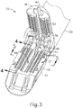
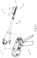
- FIGS. 1-7 depict an exemplary surgical stapling and severing instrument (10) that is sized for insertion, in a nonarticulated state as depicted in FIG. 1 , through a trocar cannula to a surgical site in a patient for performing a surgical procedure.
- a trocar may be inserted in a patient's abdomen, between two of the patient's ribs, or elsewhere.
- instrument (10) is used without a trocar.
- instrument (10) may be inserted directly through a thoracotomy or other type of incision.
- Instrument (10) of the present example includes a handle portion (20) connected to a shaft (22).
- articulation joint (11) may be remotely articulated, as depicted in phantom in FIG. 1 , by an articulation control (13), such that end effector (12) may be deflected from the longitudinal axis (LA) of shaft (22) at a desired angle ( ⁇ ). End effector (12) may thereby reach behind an organ or approach tissue from a desired angle or for other reasons.
- articulation joint (11) enables deflection of end effector (12) along a single plane.
- articulation joint (11) enables deflection of end effector along more than one plane.
- Articulation joint (11) and articulation control (13) may be configured in accordance with the teachings of any of the numerous references that are cited herein.
- articulation joint (11) and/or articulation control (13) may have any other suitable configuration.
- articulation control (13) may instead be configured as a knob that rotates about an axis that is perpendicular to the longitudinal axis (LA) of shaft (22).
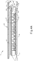
- Firing beam cap (44) slidably engages a lower surface of lower jaw (16) by having firing beam (14) extend through lower jaw slot (45) (shown in FIG. 4B ) that is formed through lower jaw (16).
- Middle pin (46) slidingly engages a top surface of lower jaw (16), cooperating with firing beam cap (44). Thereby, firing beam (14) affirmatively spaces end effector (12) during firing.
- end effector (12) could be rotated such that when the user views end effector (12), anvil (18) is visible by the user. It may be desirable to provide visibility of the surgical site for the user beyond what is possible in instrument (10) of FIG. 1 . For instance, in the case of some surgical procedures where fluid carrying vessels are transected and stapled, it may be desirable to have visual confirmation that anvil (18) and lower jaw (16) completely cover the vessel to be cut, such that the vessel may be fully cut and stapled in one single actuation. In other words, the user may wish to avoid cutting and stapling only a portion of a vessel.
- Viewing angle ( ⁇ ) may establish the relative visibility that a user has regarding distal tip (219).
- the user can see in front of distal tip (219) along any line of sight that passes through the intersection of sight line (240) and longitudinal axis (LA) within viewing angle ( ⁇ ).
- viewing angle ( ⁇ ) defines an angle greater than 90 degrees.
- viewing angle ( ⁇ ) defines an angle greater than 135 degrees.
- end effector (212) may not lend itself well to marching operations, as distal tip (219) may impart trauma to tissue that is not gathered into the space between anvil (218) and lower jaw (216) as anvil (218) is closed toward lower jaw (216).
- end effector (212) may be best suited for cutting and stapling operations (e.g., vessel transection) where all of the tissue that is to be cut and stapled is gathered proximal to distal tip (219).
- end effectors (12, 212) that provides the marching capabilities of end effector (12), the improved visibility associated with end effector (212), and the tissue gathering capabilities of end effector (212), without providing an increased risk of trauma that might otherwise be associated with fully rigid versions of end effector (212).
- an anvil has a distal tip that is resiliently biased to assume a bent or angled configuration like distal tip (219); yet the resiliently biased distal tip is deflectable away from the lower jaw in response to a sufficient load on the distal tip.
- instrument (310) may be configured in accordance with at least some of the teachings of U.S. Pub. No. 2017/0086823, entitled "Surgical Stapling Instrument with Shaft Release, Powered Firing, and Powered Articulation," published March 30, 2017 .
- Other suitable components, features, and configurations for providing instrument (310) with a modular configuration will be apparent to those of ordinary skill in the art in view of the teachings herein.
- instrument (10) may be modified to incorporate a modular configuration as shown and described with respect to instrument (310) or other instruments described herein.
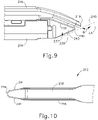
- instrument (310) comprises an end effector (312) having an anvil (318) that has an angled distal tip (319). Furthermore, distal tip (319) of anvil (318) is elastically deformable. In this manner, and as shown best in FIGS. 12A and 12B , angled distal tip (319) is operable to elastically deform from a first angled position to a second position.
- the second position for angled distal tip (319) may be substantially straight in some versions, but may be angled to a degree (e.g., slightly above or slightly below the longitudinal axis (A1) in other versions.
- angles ( ⁇ 1, ⁇ 2) are relative to longitudinal axis (A1), and the sum of angles ( ⁇ 1, ⁇ 2) represent the range of motion distal tip (319) undergoes.
- angle ( ⁇ 1) is between about 20 and about 70 degrees, or more particularly between about 30 degrees and about 50 degrees, in a downward direction from longitudinal axis (A1) toward cartridge (37).
- angle ( ⁇ 2) is between about 0 and about 90 degrees in an upward direction from longitudinal axis (Al) away from cartridge (37).
- the range of motion undergone by tip (319) is between about 20 degrees and about 110 degrees.
- the angles described for angles ( ⁇ 1, ⁇ 2) are exemplary only and not limiting. Other suitable angles will be apparent to those of ordinary skill in the art in view of the teachings herein.
- tissue (90) When tissue (90) is clamped between a closed cartridge (537) and anvil (518), the user can look to see where anvil (518) has clamped tissue (90). Furthermore, the user can determine whether the tissue is completely clamped between anvil (518) and cartridge (537) such that tissue does not spill over the end of end effector (512). The user may be able to also visualize the quality of the clamp between anvil (518) and cartridge (537) against tissue (90). It will be appreciated that in some instances, end effector (512) may be rotated before, during, or after clamping tissue (90). As a result, the shape of anvil (518) may also provide more accessible viewing of distal tip (519).
- anvil (618) may provide an atraumatic tissue deflection surface as anvil (618) contacts or moves through tissue.
- atraumatic tissue deflection may include urging tissue (e.g., a large vessel) proximally into the space between anvil (618) and lower jaw (616) as anvil (618) closes toward lower jaw (616).
- tissue e.g., a large vessel
- the shape of anvil (618) may also provide better maneuverability of end effector (612) and better visibility of the distal end of end effector (612) in relation to anatomical structures at the surgical site.
- Other suitable variations of anvil (618) will be apparent to one of ordinary skill in the art in view of the teachings herein.
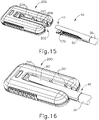
- FIGS. 15 and 16 illustrate an exemplary end effector (40) configured to apply a buttress to a tissue site where a cutting and stapling operation is performed.
- End effector (40) includes distal end (141) and is connected with a shaft assembly (30).
- End effector (40) comprises an anvil (60), a lower jaw (50), and a staple cartridge (170) received by lower jaw (50).
- end effector (40) may be used in place of end effector (12) of instrument (10).
- End effector (40) may be integrally formed with instrument (10) or in the alternative may be interchangeable with end effector (12) of instrument (10).
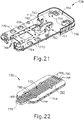
- Buttress applier cartridge (716) further includes a housing assembly (724) having an upper housing (726) and a lower housing (728), which each generally define a "U" shape to present open end (718).
- Various components are interposed between upper and lower housings (726, 728).
- these components include a chassis (736) supporting a platform (730), which is also referred to as a compression layer (730).
- Upper adhesive layer (742) is provided on outer layer of buttress (714) in order to adhere buttress (714) within end effectors described herein. Adherence of the buttress (714) can occur through a variety of mechanisms including but not limited to a pressure sensitive adhesive. In the case of pressure sensitive adhesion, adhesion occurs upon the application of at least a predetermined minimum force.
- each adhesive layer (742) includes a pressure sensitive adhesive material. Examples of various suitable materials that may be used to form adhesive layers (742) are disclosed in U.S. Pat. Pub. No. 2016/0278774, entitled "Method of Applying a Buttress to a Surgical Stapler," published September 29, 2016 . Alternatively, any other suitable materials may be used. As shown in the present example, adhesive layer (742) is applied to form a continuous outer seal to enhance longevity once applied to an end effector.
- adhesive may include (but is not limited to) tacky materials and also materials that are pliable or wax-like and adhere to a complex geometry via deformation and conformance. Some suitable adhesives may provide such pliability to adhere to a complex geometry via deformation and conformance without necessarily providing a high initial tack. In some instances, adhesives with lower tackiness may be removed more cleanly from surfaces.
- suitable materials that may be used to form adhesive layers (742) will be apparent to those of ordinary skill in the art in view of the teachings herein.
- Each actuator sled (752, 754) includes a pair of arms (755a, 755b) extending laterally inward to selectively and releasably secure buttress assemblies (712) to platform (730).
- Arms (755a, 755b) may also be referred to as retaining features or retention members, similar to the retaining features (204) described above with respect to applicator (200) in FIGS. 15 and 16 .
- FIG. 20 show arms (755a, 755b) positioned such that buttress assemblies (712) are interposed between the free ends of arms (755a, 755b) and platform (730).
- pad (772) is formed with varying stiffness along its longitudinal length to simultaneously provide sufficient reactionary forces of at least the predetermined minimum force for adhesion while accommodating a parallel-camber orientation, an over-camber orientation, and an under-camber orientation of an end effector as discussed below in greater detail.
- parallel-camber orientation refers to an upper jaw and a lower jaw of an end effector being functionally parallel to each other.
- over-camber orientation refers to an upper jaw of an end effector being over rotated relative a lower jaw of an end effector.
- under-camber orientation refers to an upper jaw being under rotated relative to a lower jaw of an end effector.
- a distal cantilever catch (796) laterally extends to the left from the distal portion of upper left sled body (790), and a proximal cantilever catch (798) laterally extends to the left from the proximal portion of upper left sled body (790).
- Distal and proximal cantilever catches (796, 798) are respectively portions of distal and proximal detent couplings (800, 802) discussed below in greater detail.
- each distal cantilever catch (796) is respectively engaged with each distal ground cam (814), and each proximal cantilever catch (798) is respectively engaged with each proximal ground cam (816) to urge left and right actuator sleds (752, 754) inward toward the restraint position.
- Directing left and right actuator sleds (752, 754) outward from the restraint position toward the release position as shown in FIG. 32 resiliently deflects distal and proximal cantilever catches (796, 798) as distal and proximal cantilever catches (796, 798) follow distal and proximal ground cams (814, 816).
- an alternate opening similar to opening (701) described above, can be incorporated into a buttress applier cartridge to accommodate an end effector having a curved tip.
- those buttress applier cartridges described herein can also include one or more alignment features configured to align the end effector of the surgical stapler with the buttress assemblies prior to applying the buttress assemblies to the end effector.
- those buttress applier cartridges comprise an alignment feature connectable with the platform and extending proximally therefrom.
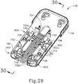
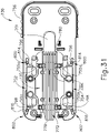
- buttress applier cartridge assembly (2110) is shown, which is similar to buttress applier cartridge assembly (710) shown and described above. To that extent, the teachings above with respect to buttress applier cartridge assembly (710) apply equally to buttress applier cartridge assembly (2110) except for the differences described below.
- Buttress applier cartridge assembly (2110) comprises buttress applier cartridge (2116) having housing assembly (724), which has upper housing (726) and lower housing (728).
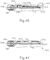
- housing assembly (724) defines a channel (2103) that is open at a proximal end and configured to accommodate an end effector, such as end effector (1012) as shown in FIGS. 39 and 41 .
- platform (2130) is configured to retain buttress assemblies (712) in the same manner as described above with respect to buttress applier cartridge (716).
- platform (2130) is compressible and also extends proximally to distally such that the space or area defined by channel (2103) is encompassed by platform (2130).
- platform (2130) Near a distal end of channel (2103), platform (2130) includes opening (2101), which is defined by a hole or cut-out in platform (2130).
- opening (2101) is located distal to where one or more buttress assemblies (712) are supported or supportable by platform (2130).
- opening (2101) comprises a U-shaped cut-out.
- Alignment feature (2132) is configured as a proximal alignment feature. In this way, alignment feature (2132) is configured to engage or contact a proximal edge or one or more tissue stops of the end effector when the end effector is open prior to clamping but fully positioned with buttress applier cartridge (2116) within channel (2103). In some instances, the proximal edge or one or more tissue stops of the end effector may be located on the jaw of the end effector comprising the staple cartridge. In some other instances, the proximal edge or one or more tissue stops of the end effector may be located on the jaw of the end effector comprising the anvil.
- alignment feature (2132) guides the end effector to align the end effector relative to the buttress assemblies (712) supported by the buttress applier cartridge.
- alignment feature (2132) is configured as a proximal alignment feature that aligns a longitudinal position of the end effector, including aligning the distal part of the end effector.
- opening (2101) deforms such that the portion of platform (2130) around opening (2101) deflects downward away from curved tip (1014) as curved tip (1014) contacts platform (2130) and pushes platform (2130) downward.
- alignment features with a buttress applier cartridge that align an end effector of a surgical stapler with the buttress applier cartridge, or ways to modify alignment feature (2132) for use with such an end effector will be apparent to those of ordinary skill in the art.
Landscapes
- Health & Medical Sciences (AREA)
- Life Sciences & Earth Sciences (AREA)
- Surgery (AREA)
- Heart & Thoracic Surgery (AREA)
- Engineering & Computer Science (AREA)
- Biomedical Technology (AREA)
- Nuclear Medicine, Radiotherapy & Molecular Imaging (AREA)
- Medical Informatics (AREA)
- Molecular Biology (AREA)
- Animal Behavior & Ethology (AREA)
- General Health & Medical Sciences (AREA)
- Public Health (AREA)
- Veterinary Medicine (AREA)
- Surgical Instruments (AREA)
Claims (17)
- Cartouche d'applicateur de contrefort (2116) configurée pour retenir un ou plusieurs ensembles de contrefort (712), la cartouche d'applicateur de contrefort étant en outre configurée pour être utilisée avec un effecteur d'extrémité d'une agrafeuse chirurgicale pour appliquer le ou les ensembles de contrefort à un ou plusieurs ensembles sélectionnés parmi une première mâchoire et une seconde mâchoire de l'effecteur d'extrémité, la première mâchoire de l'effecteur d'extrémité comprenant une enclume et la seconde mâchoire de l'effecteur d'extrémité comprenant une cartouche d'agrafes, la cartouche d'applicateur de contrefort comprenant :(a) un ensemble boîtier (724) ayant une extrémité proximale et une extrémité distale, l'ensemble boîtier définissant un canal (2103) s'étendant longitudinalement et configuré pour recevoir l'effecteur d'extrémité ;(b) une plate-forme (2130), pouvant être reliée directement ou indirectement à l'ensemble boîtier, la plate-forme s'étendant longitudinalement à l'intérieur d'une zone définie par le canal, la plate-forme étant configurée pour supporter le ou les ensembles de contrefort sur celle-ci ;(c) une ouverture (2101) qui s'étend transversalement d'un premier côté de la plate-forme à un second côté de la plate-forme opposé au premier côté de la plate-forme, l'ouverture étant configurée pour recevoir une extrémité courbée de l'effecteur d'extrémité permettant à au moins une partie de l'extrémité courbée de s'étendre du premier côté de la plate-forme au second côté de la plate-forme ; et caractérisée en ce que la cartouche d'applicateur de contrefort comprend en outre :
(d) une caractéristique d'alignement (2132), la caractéristique d'alignement pouvant être reliée à la plate-forme et s'étendant de manière proximale à partir de celle-ci, la caractéristique d'alignement étant configurée pour entrer en contact avec une butée de tissu de l'effecteur d'extrémité lorsque l'effecteur d'extrémité est entièrement positionné à l'intérieur du canal défini par l'ensemble boîtier. - Cartouche d'applicateur de contrefort selon la revendication 1, la caractéristique d'alignement (2132) étant rigide.
- Cartouche d'applicateur de contrefort selon la revendication 1 ou la revendication 2, la caractéristique d'alignement (2132) étant plus mince que la plate-forme.
- Cartouche d'applicateur de contrefort selon l'une quelconque des revendications précédentes, la caractéristique d'alignement (2132) étant positionnée entre l'endroit où le ou les ensembles de contrefort peuvent être supportés par la plate-forme.
- Cartouche d'applicateur de contrefort selon l'une quelconque des revendications précédentes, la caractéristique d'alignement (2132) s'étendant orthogonalement par rapport au canal s'étendant longitudinalement (2130) de telle sorte que la caractéristique d'alignement s'étend à travers une ligne de coupe définie par l'effecteur d'extrémité lorsque l'effecteur d'extrémité est positionné dans le canal.
- Cartouche d'applicateur de contrefort selon l'une quelconque des revendications précédentes, la caractéristique d'alignement (2132) pouvant être reliée à une extrémité proximale de la plate-forme.
- Cartouche d'applicateur de contrefort selon l'une quelconque des revendications précédentes, la caractéristique d'alignement (2132) étant configurée pour guider l'extrémité courbée de l'effecteur d'extrémité pour aligner l'extrémité courbée de l'effecteur d'extrémité avec l'ouverture.
- Cartouche d'applicateur de contrefort selon l'une quelconque des revendications précédentes, la plate-forme (2130) augmentant en épaisseur d'une partie proximale (2178) à une partie distale (2180).
- Cartouche d'applicateur de contrefort selon l'une quelconque des revendications précédentes, la plate-forme (2130) étant compressible.
- Cartouche d'applicateur de contrefort selon l'une quelconque des revendications précédentes, comprenant en outre un châssis (2136), le châssis étant relié à l'ensemble boîtier et la plate-forme (2130) étant relié au châssis (2136).
- Cartouche d'applicateur de contrefort selon l'une quelconque des revendications précédentes, l'ouverture (2101) comprenant une découpe en forme de U.
- Cartouche d'applicateur de contrefort selon l'une quelconque des revendications précédentes, l'ouverture (2101) étant située de manière distale par rapport à l'endroit où le ou les ensembles de contrefort (712) peuvent être supportés par la plate-forme.
- Cartouche d'applicateur de contrefort selon l'une quelconque des revendications précédentes, le serrage de l'effecteur d'extrémité sur la plate-forme (2130) amenant l'extrémité courbée de l'effecteur d'extrémité à s'étendre au moins partiellement à travers l'ouverture (2101).
- Cartouche d'applicateur de contrefort selon l'une quelconque des revendications précédentes, l'ouverture (2101) se déformant lorsque l'extrémité courbée passe à travers l'ouverture.
- Cartouche d'applicateur de contrefort selon l'une quelconque des revendications précédentes, l'ouverture (2130) et la caractéristique d'alignement (2132) étant espacées de telle sorte que, lorsque les butées de tissu de l'effecteur d'extrémité entrent en contact avec la caractéristique d'alignement et que l'effecteur d'extrémité est serré, l'extrémité courbée de l'effecteur d'extrémité s'aligne avec l'ouverture et s'étend à travers l'ouverture.
- Cartouche d'applicateur de contrefort selon l'une quelconque des revendications précédentes, configurée en outre de telle sorte qu'un bord proximal d'une sélection de la première mâchoire et de la seconde mâchoire de l'effecteur d'extrémité est configuré pour aligner une position longitudinale de l'effecteur d'extrémité par rapport à la plate-forme (2130) et au ou aux ensembles de contrefort configurés pour être supportés par la plate-forme.
- Cartouche d'applicateur de contrefort selon l'une quelconque des revendications précédentes, l'extrémité courbée de l'effecteur d'extrémité étant une extrémité de dissection.
Priority Applications (2)
| Application Number | Priority Date | Filing Date | Title |
|---|---|---|---|
| EP22169173.6A EP4052659A1 (fr) | 2018-12-28 | 2019-12-23 | Applicateur d'ensemble de contrefort présentant des caractéristiques d'alignement proximales pour une agrafeuse chirurgicale à extrémité courbée |
| EP22169172.8A EP4052658B1 (fr) | 2018-12-28 | 2019-12-23 | Applicateur d'ensemble de contrefort présentant des caractéristiques d'alignement proximales pour une agrafeuse chirurgicale à extrémité courbée |
Applications Claiming Priority (1)
| Application Number | Priority Date | Filing Date | Title |
|---|---|---|---|
| US16/235,670 US10905424B2 (en) | 2018-12-28 | 2018-12-28 | Curved tip surgical stapler buttress assembly applicator with proximal alignment features |
Related Child Applications (2)
| Application Number | Title | Priority Date | Filing Date |
|---|---|---|---|
| EP22169173.6A Division EP4052659A1 (fr) | 2018-12-28 | 2019-12-23 | Applicateur d'ensemble de contrefort présentant des caractéristiques d'alignement proximales pour une agrafeuse chirurgicale à extrémité courbée |
| EP22169172.8A Division EP4052658B1 (fr) | 2018-12-28 | 2019-12-23 | Applicateur d'ensemble de contrefort présentant des caractéristiques d'alignement proximales pour une agrafeuse chirurgicale à extrémité courbée |
Publications (2)
| Publication Number | Publication Date |
|---|---|
| EP3673823A1 EP3673823A1 (fr) | 2020-07-01 |
| EP3673823B1 true EP3673823B1 (fr) | 2022-04-27 |
Family
ID=69005607
Family Applications (3)
| Application Number | Title | Priority Date | Filing Date |
|---|---|---|---|
| EP22169172.8A Active EP4052658B1 (fr) | 2018-12-28 | 2019-12-23 | Applicateur d'ensemble de contrefort présentant des caractéristiques d'alignement proximales pour une agrafeuse chirurgicale à extrémité courbée |
| EP22169173.6A Withdrawn EP4052659A1 (fr) | 2018-12-28 | 2019-12-23 | Applicateur d'ensemble de contrefort présentant des caractéristiques d'alignement proximales pour une agrafeuse chirurgicale à extrémité courbée |
| EP19219391.0A Active EP3673823B1 (fr) | 2018-12-28 | 2019-12-23 | Applicateur d'ensemble de contrefort présentant des caractéristiques d'alignement proximales pour une agrafeuse chirurgicale à extrémité courbée |
Family Applications Before (2)
| Application Number | Title | Priority Date | Filing Date |
|---|---|---|---|
| EP22169172.8A Active EP4052658B1 (fr) | 2018-12-28 | 2019-12-23 | Applicateur d'ensemble de contrefort présentant des caractéristiques d'alignement proximales pour une agrafeuse chirurgicale à extrémité courbée |
| EP22169173.6A Withdrawn EP4052659A1 (fr) | 2018-12-28 | 2019-12-23 | Applicateur d'ensemble de contrefort présentant des caractéristiques d'alignement proximales pour une agrafeuse chirurgicale à extrémité courbée |
Country Status (6)
| Country | Link |
|---|---|
| US (1) | US10905424B2 (fr) |
| EP (3) | EP4052658B1 (fr) |
| JP (1) | JP7460636B2 (fr) |
| CN (1) | CN113271871B (fr) |
| BR (1) | BR112021012454A2 (fr) |
| WO (1) | WO2020136492A1 (fr) |
Families Citing this family (15)
| Publication number | Priority date | Publication date | Assignee | Title |
|---|---|---|---|---|
| EP4344684A3 (fr) | 2013-12-17 | 2024-10-09 | Standard Bariatrics Inc. | Guide de ligne de résection pour une procédure médicale |
| EP3125796B1 (fr) | 2014-03-29 | 2024-03-06 | Standard Bariatrics Inc. | Dispositifs d'agrafage chirurgical |
| EP3125779B1 (fr) | 2014-03-29 | 2023-10-25 | Standard Bariatrics, Inc. | Effecteurs pour dispositifs d'agrafage chirurgical |
| US10285837B1 (en) | 2015-09-16 | 2019-05-14 | Standard Bariatrics, Inc. | Systems and methods for measuring volume of potential sleeve in a sleeve gastrectomy |
| US10542981B2 (en) | 2016-11-14 | 2020-01-28 | Ethicon Llc | Atraumatic stapling head features for circular surgical stapler |
| US10912562B2 (en) * | 2017-08-14 | 2021-02-09 | Standard Bariatrics, Inc. | End effectors, surgical stapling devices, and methods of using same |
| USD903115S1 (en) * | 2018-12-28 | 2020-11-24 | Ethicon Llc | Applicator for a surgical stapler buttress |
| USD926317S1 (en) | 2018-12-28 | 2021-07-27 | Cilag Gmbh International | Surgical stapler deck with tissue engagement cleat features |
| USD926318S1 (en) | 2018-12-28 | 2021-07-27 | Cilag Gmbh International | Surgical stapler deck with tissue engagement recess features |
| US11202628B2 (en) | 2018-12-28 | 2021-12-21 | Cilag Gmbh International | Surgical stapler with tissue engagement features around tissue containment pin |
| USD901686S1 (en) * | 2018-12-28 | 2020-11-10 | Ethicon Llc | Applicator for surgical stapler buttress |
| US11033269B2 (en) | 2018-12-28 | 2021-06-15 | Cilag Gmbh International | Method of applying buttresses to surgically cut and stapled sites |
| CN114641265A (zh) | 2019-11-04 | 2022-06-17 | 标准肥胖病研究公司 | 在手术期间使用拉普拉斯定律张力回缩进行手术的系统和方法 |
| AU2021300228A1 (en) | 2020-06-30 | 2023-02-09 | Standard Bariatrics, Inc. | Systems, devices, and methods for preventing or reducing loss of insufflation during a laparoscopic surgical procedure |
| MX2023011134A (es) | 2021-03-23 | 2023-10-04 | Standard Bariatrics Inc | Sistemas y metodos para prevenir la migracion de tejidos en grapadoras quirurgicas. |
Family Cites Families (125)
| Publication number | Priority date | Publication date | Assignee | Title |
|---|---|---|---|---|
| US4805823A (en) | 1988-03-18 | 1989-02-21 | Ethicon, Inc. | Pocket configuration for internal organ staplers |
| US5657429A (en) | 1992-08-10 | 1997-08-12 | Computer Motion, Inc. | Automated endoscope system optimal positioning |
| US5415334A (en) | 1993-05-05 | 1995-05-16 | Ethicon Endo-Surgery | Surgical stapler and staple cartridge |
| EP0699053B1 (fr) | 1993-05-14 | 1999-03-17 | Sri International | Appareil chirurgical |
| US5465895A (en) | 1994-02-03 | 1995-11-14 | Ethicon Endo-Surgery, Inc. | Surgical stapler instrument |
| US5597107A (en) | 1994-02-03 | 1997-01-28 | Ethicon Endo-Surgery, Inc. | Surgical stapler instrument |
| US5704534A (en) | 1994-12-19 | 1998-01-06 | Ethicon Endo-Surgery, Inc. | Articulation assembly for surgical instruments |
| US5632432A (en) | 1994-12-19 | 1997-05-27 | Ethicon Endo-Surgery, Inc. | Surgical instrument |
| US5902312A (en) * | 1995-07-03 | 1999-05-11 | Frater; Dirk A. | System for mounting bolster material on tissue staplers |
| US5814055A (en) | 1995-09-19 | 1998-09-29 | Ethicon Endo-Surgery, Inc. | Surgical clamping mechanism |
| US5792135A (en) | 1996-05-20 | 1998-08-11 | Intuitive Surgical, Inc. | Articulated surgical instrument for performing minimally invasive surgery with enhanced dexterity and sensitivity |
| US6364888B1 (en) | 1996-09-09 | 2002-04-02 | Intuitive Surgical, Inc. | Alignment of master and slave in a minimally invasive surgical apparatus |
| US5752965A (en) * | 1996-10-21 | 1998-05-19 | Bio-Vascular, Inc. | Apparatus and method for producing a reinforced surgical fastener suture line |
| US6331181B1 (en) | 1998-12-08 | 2001-12-18 | Intuitive Surgical, Inc. | Surgical robotic tools, data architecture, and use |
| US6231565B1 (en) | 1997-06-18 | 2001-05-15 | United States Surgical Corporation | Robotic arm DLUs for performing surgical tasks |
| US6459926B1 (en) | 1998-11-20 | 2002-10-01 | Intuitive Surgical, Inc. | Repositioning and reorientation of master/slave relationship in minimally invasive telesurgery |
| US6638285B2 (en) * | 2001-04-16 | 2003-10-28 | Shlomo Gabbay | Biological tissue strip and system and method to seal tissue |
| US6783524B2 (en) | 2001-04-19 | 2004-08-31 | Intuitive Surgical, Inc. | Robotic surgical tool with ultrasound cauterizing and cutting instrument |
| ATE547992T1 (de) | 2001-06-29 | 2012-03-15 | Intuitive Surgical Operations | Gelenkmechanismus fuer plattformverbindung |
| US6939358B2 (en) | 2001-12-20 | 2005-09-06 | Gore Enterprise Holdings, Inc. | Apparatus and method for applying reinforcement material to a surgical stapler |
| US7380696B2 (en) | 2003-05-20 | 2008-06-03 | Ethicon Endo-Surgery, Inc. | Articulating surgical stapling instrument incorporating a two-piece E-beam firing mechanism |
| US7143923B2 (en) | 2003-05-20 | 2006-12-05 | Ethicon Endo-Surgery, Inc. | Surgical stapling instrument having a firing lockout for an unclosed anvil |
| US9060770B2 (en) | 2003-05-20 | 2015-06-23 | Ethicon Endo-Surgery, Inc. | Robotically-driven surgical instrument with E-beam driver |
| US7380695B2 (en) | 2003-05-20 | 2008-06-03 | Ethicon Endo-Surgery, Inc. | Surgical stapling instrument having a single lockout mechanism for prevention of firing |
| US6978921B2 (en) | 2003-05-20 | 2005-12-27 | Ethicon Endo-Surgery, Inc. | Surgical stapling instrument incorporating an E-beam firing mechanism |
| US7303108B2 (en) | 2003-09-29 | 2007-12-04 | Ethicon Endo-Surgery, Inc. | Surgical stapling instrument incorporating a multi-stroke firing mechanism with a flexible rack |
| US7434715B2 (en) | 2003-09-29 | 2008-10-14 | Ethicon Endo-Surgery, Inc. | Surgical stapling instrument having multistroke firing with opening lockout |
| US20050070929A1 (en) * | 2003-09-30 | 2005-03-31 | Dalessandro David A. | Apparatus and method for attaching a surgical buttress to a stapling apparatus |
| US7147139B2 (en) | 2003-12-30 | 2006-12-12 | Ethicon Endo-Surgery, Inc | Closure plate lockout for a curved cutter stapler |
| US7134587B2 (en) | 2003-12-30 | 2006-11-14 | Ethicon Endo-Surgery, Inc. | Knife retraction arm for a curved cutter stapler |
| US20050139636A1 (en) | 2003-12-30 | 2005-06-30 | Schwemberger Richard F. | Replaceable cartridge module for a surgical stapling and cutting instrument |
| US7207472B2 (en) | 2003-12-30 | 2007-04-24 | Ethicon Endo-Surgery, Inc. | Cartridge with locking knife for a curved cutter stapler |
| US20050143759A1 (en) | 2003-12-30 | 2005-06-30 | Kelly William D. | Curved cutter stapler shaped for male pelvis |
| US7147140B2 (en) | 2003-12-30 | 2006-12-12 | Ethicon Endo - Surgery, Inc. | Cartridge retainer for a curved cutter stapler |
| US20050145672A1 (en) | 2003-12-30 | 2005-07-07 | Schwemberger Richard F. | Curved cutter stapler with aligned tissue retention feature |
| US6988650B2 (en) | 2003-12-30 | 2006-01-24 | Ethicon Endo-Surgery, Inc. | Retaining pin lever advancement mechanism for a curved cutter stapler |
| US7204404B2 (en) | 2003-12-30 | 2007-04-17 | Ethicon Endo-Surgery, Inc. | Slotted pins guiding knife in a curved cutter stapler |
| GB2451776B (en) * | 2004-02-17 | 2009-04-08 | Cook Biotech Inc | Medical devices and methods useful for applying bolster material |
| US7367485B2 (en) | 2004-06-30 | 2008-05-06 | Ethicon Endo-Surgery, Inc. | Surgical stapling instrument incorporating a multistroke firing mechanism having a rotary transmission |
| US8579176B2 (en) | 2005-07-26 | 2013-11-12 | Ethicon Endo-Surgery, Inc. | Surgical stapling and cutting device and method for using the device |
| US8800838B2 (en) | 2005-08-31 | 2014-08-12 | Ethicon Endo-Surgery, Inc. | Robotically-controlled cable-based surgical end effectors |
| US7644848B2 (en) | 2006-01-31 | 2010-01-12 | Ethicon Endo-Surgery, Inc. | Electronic lockouts and surgical instrument including same |
| US7845537B2 (en) | 2006-01-31 | 2010-12-07 | Ethicon Endo-Surgery, Inc. | Surgical instrument having recording capabilities |
| US20110290856A1 (en) | 2006-01-31 | 2011-12-01 | Ethicon Endo-Surgery, Inc. | Robotically-controlled surgical instrument with force-feedback capabilities |
| US8992422B2 (en) | 2006-03-23 | 2015-03-31 | Ethicon Endo-Surgery, Inc. | Robotically-controlled endoscopic accessory channel |
| US20070246505A1 (en) * | 2006-04-24 | 2007-10-25 | Medical Ventures Inc. | Surgical buttress assemblies and methods of uses thereof |
| US7721930B2 (en) | 2006-11-10 | 2010-05-25 | Thicon Endo-Surgery, Inc. | Disposable cartridge with adhesive for use with a stapling device |
| US8684253B2 (en) | 2007-01-10 | 2014-04-01 | Ethicon Endo-Surgery, Inc. | Surgical instrument with wireless communication between a control unit of a robotic system and remote sensor |
| US20080169328A1 (en) | 2007-01-11 | 2008-07-17 | Shelton Frederick E | Buttress material for use with a surgical stapler |
| US8011550B2 (en) * | 2009-03-31 | 2011-09-06 | Tyco Healthcare Group Lp | Surgical stapling apparatus |
| US8413871B2 (en) * | 2007-03-06 | 2013-04-09 | Covidien Lp | Surgical stapling apparatus |
| US8931682B2 (en) | 2007-06-04 | 2015-01-13 | Ethicon Endo-Surgery, Inc. | Robotically-controlled shaft based rotary drive systems for surgical instruments |
| US8408439B2 (en) | 2007-06-22 | 2013-04-02 | Ethicon Endo-Surgery, Inc. | Surgical stapling instrument with an articulatable end effector |
| EP2205164B1 (fr) * | 2007-10-08 | 2013-07-03 | Gore Enterprise Holdings, Inc. | Dispositif pour fournir un renforcement des lignes d'agrafage en chirurgie |
| US8348129B2 (en) | 2009-10-09 | 2013-01-08 | Ethicon Endo-Surgery, Inc. | Surgical stapler having a closure mechanism |
| US8573465B2 (en) | 2008-02-14 | 2013-11-05 | Ethicon Endo-Surgery, Inc. | Robotically-controlled surgical end effector system with rotary actuated closure systems |
| US9179912B2 (en) | 2008-02-14 | 2015-11-10 | Ethicon Endo-Surgery, Inc. | Robotically-controlled motorized surgical cutting and fastening instrument |
| US8371491B2 (en) | 2008-02-15 | 2013-02-12 | Ethicon Endo-Surgery, Inc. | Surgical end effector having buttress retention features |
| US8091756B2 (en) * | 2008-05-09 | 2012-01-10 | Tyco Healthcare Group Lp | Varying tissue compression using take-up component |
| US9386983B2 (en) | 2008-09-23 | 2016-07-12 | Ethicon Endo-Surgery, Llc | Robotically-controlled motorized surgical instrument |
| US8210411B2 (en) | 2008-09-23 | 2012-07-03 | Ethicon Endo-Surgery, Inc. | Motor-driven surgical cutting instrument |
| US8365972B2 (en) * | 2009-03-31 | 2013-02-05 | Covidien Lp | Surgical stapling apparatus |
| US8220688B2 (en) | 2009-12-24 | 2012-07-17 | Ethicon Endo-Surgery, Inc. | Motor-driven surgical cutting instrument with electric actuator directional control assembly |
| US8801734B2 (en) | 2010-07-30 | 2014-08-12 | Ethicon Endo-Surgery, Inc. | Circular stapling instruments with secondary cutting arrangements and methods of using same |
| US9220500B2 (en) * | 2010-09-30 | 2015-12-29 | Ethicon Endo-Surgery, Inc. | Tissue thickness compensator comprising structure to produce a resilient load |
| US9839420B2 (en) | 2010-09-30 | 2017-12-12 | Ethicon Llc | Tissue thickness compensator comprising at least one medicament |
| US8579990B2 (en) | 2011-03-30 | 2013-11-12 | Ethicon, Inc. | Tissue repair devices of rapid therapeutic absorbency |
| US9492170B2 (en) | 2011-08-10 | 2016-11-15 | Ethicon Endo-Surgery, Inc. | Device for applying adjunct in endoscopic procedure |
| US9101359B2 (en) | 2011-09-13 | 2015-08-11 | Ethicon Endo-Surgery, Inc. | Surgical staple cartridge with self-dispensing staple buttress |
| US8998060B2 (en) | 2011-09-13 | 2015-04-07 | Ethicon Endo-Surgery, Inc. | Resistive heated surgical staple cartridge with phase change sealant |
| US9999408B2 (en) | 2011-09-14 | 2018-06-19 | Ethicon Endo-Surgery, Inc. | Surgical instrument with fluid fillable buttress |
| US8814025B2 (en) | 2011-09-15 | 2014-08-26 | Ethicon Endo-Surgery, Inc. | Fibrin pad matrix with suspended heat activated beads of adhesive |
| US20130068816A1 (en) | 2011-09-15 | 2013-03-21 | Venkataramanan Mandakolathur Vasudevan | Surgical instrument and buttress material |
| US20130075447A1 (en) | 2011-09-22 | 2013-03-28 | II William B. Weisenburgh | Adjunct therapy device for applying hemostatic agent |
| US9393018B2 (en) | 2011-09-22 | 2016-07-19 | Ethicon Endo-Surgery, Inc. | Surgical staple assembly with hemostatic feature |
| US9198644B2 (en) | 2011-09-22 | 2015-12-01 | Ethicon Endo-Surgery, Inc. | Anvil cartridge for surgical fastening device |
| US9050084B2 (en) * | 2011-09-23 | 2015-06-09 | Ethicon Endo-Surgery, Inc. | Staple cartridge including collapsible deck arrangement |
| US8899464B2 (en) | 2011-10-03 | 2014-12-02 | Ethicon Endo-Surgery, Inc. | Attachment of surgical staple buttress to cartridge |
| US8584920B2 (en) * | 2011-11-04 | 2013-11-19 | Covidien Lp | Surgical stapling apparatus including releasable buttress |
| RU2623130C2 (ru) | 2012-02-14 | 2017-06-22 | Этикон Эндо-Серджери, Инк. | Линейный сшивающий аппарат |
| US9198662B2 (en) * | 2012-03-28 | 2015-12-01 | Ethicon Endo-Surgery, Inc. | Tissue thickness compensator having improved visibility |
| US9433420B2 (en) * | 2013-01-23 | 2016-09-06 | Covidien Lp | Surgical apparatus including surgical buttress |
| US9386984B2 (en) * | 2013-02-08 | 2016-07-12 | Ethicon Endo-Surgery, Llc | Staple cartridge comprising a releasable cover |
| US10092292B2 (en) | 2013-02-28 | 2018-10-09 | Ethicon Llc | Staple forming features for surgical stapling instrument |
| US9839421B2 (en) | 2013-02-28 | 2017-12-12 | Ethicon Llc | Jaw closure feature for end effector of surgical instrument |
| US9717497B2 (en) | 2013-02-28 | 2017-08-01 | Ethicon Llc | Lockout feature for movable cutting member of surgical instrument |
| US9186142B2 (en) | 2013-02-28 | 2015-11-17 | Ethicon Endo-Surgery, Inc. | Surgical instrument end effector articulation drive with pinion and opposing racks |
| US9517065B2 (en) | 2013-02-28 | 2016-12-13 | Ethicon Endo-Surgery, Llc | Integrated tissue positioning and jaw alignment features for surgical stapler |
| US9795379B2 (en) | 2013-02-28 | 2017-10-24 | Ethicon Llc | Surgical instrument with multi-diameter shaft |
| US9622746B2 (en) | 2013-02-28 | 2017-04-18 | Ethicon Endo-Surgery, Llc | Distal tip features for end effector of surgical instrument |
| US9867615B2 (en) | 2013-02-28 | 2018-01-16 | Ethicon Llc | Surgical instrument with articulation lock having a detenting binary spring |
| US9808248B2 (en) | 2013-02-28 | 2017-11-07 | Ethicon Llc | Installation features for surgical instrument end effector cartridge |
| US9782169B2 (en) | 2013-03-01 | 2017-10-10 | Ethicon Llc | Rotary powered articulation joints for surgical instruments |
| US9597082B2 (en) | 2013-03-14 | 2017-03-21 | Ethicon Endo-Surgery, Llc | Method and apparatus for sealing end-to-end anastomosis |
| US8992060B2 (en) | 2013-05-08 | 2015-03-31 | Ford Global Technologies, Llc | Uniform illumination of lamps |
| US9913642B2 (en) | 2014-03-26 | 2018-03-13 | Ethicon Llc | Surgical instrument comprising a sensor system |
| US10426476B2 (en) | 2014-09-26 | 2019-10-01 | Ethicon Llc | Circular fastener cartridges for applying radially expandable fastener lines |
| US10172611B2 (en) | 2014-06-10 | 2019-01-08 | Ethicon Llc | Adjunct materials and methods of using same in surgical methods for tissue sealing |
| US9848871B2 (en) | 2014-06-10 | 2017-12-26 | Ethicon Llc | Woven and fibrous materials for reinforcing a staple line |
| US9936954B2 (en) | 2014-06-10 | 2018-04-10 | Ethicon Llc | Devices and methods for sealing staples in tissue |
| US10568621B2 (en) * | 2015-03-25 | 2020-02-25 | Ethicon Llc | Surgical staple buttress with integral adhesive for releasably attaching to a surgical stapler |
| US10548593B2 (en) * | 2015-03-25 | 2020-02-04 | Ethicon Llc | Flowable bioabsorbable polymer adhesive for releasably attaching a staple buttress to a surgical stapler |
| US10349939B2 (en) | 2015-03-25 | 2019-07-16 | Ethicon Llc | Method of applying a buttress to a surgical stapler |
| US10420558B2 (en) | 2015-07-30 | 2019-09-24 | Ethicon Llc | Surgical instrument comprising a system for bypassing an operational step of the surgical instrument |
| US11058425B2 (en) | 2015-08-17 | 2021-07-13 | Ethicon Llc | Implantable layers for a surgical instrument |
| US10166023B2 (en) | 2015-08-24 | 2019-01-01 | Ethicon Llc | Method of applying a buttress to a surgical stapler end effector |
| US11039832B2 (en) | 2015-08-24 | 2021-06-22 | Cilag Gmbh International | Surgical stapler buttress applicator with spent staple cartridge lockout |
| US10639039B2 (en) | 2015-08-24 | 2020-05-05 | Ethicon Llc | Surgical stapler buttress applicator with multi-zone platform for pressure focused release |
| US10342542B2 (en) | 2015-08-24 | 2019-07-09 | Ethicon Llc | Surgical stapler buttress applicator with end effector actuated release mechanism |
| US10342532B2 (en) * | 2015-08-24 | 2019-07-09 | Ethicon Llc | Surgical stapler buttress applicator with multi-point actuated release mechanism |
| US10349940B2 (en) | 2015-08-24 | 2019-07-16 | Ethicon Llc | Surgical stapler buttress applicator with state indicator |
| US10569071B2 (en) | 2015-08-31 | 2020-02-25 | Ethicon Llc | Medicant eluting adjuncts and methods of using medicant eluting adjuncts |
| US10182813B2 (en) | 2015-09-29 | 2019-01-22 | Ethicon Llc | Surgical stapling instrument with shaft release, powered firing, and powered articulation |
| US20170086829A1 (en) | 2015-09-30 | 2017-03-30 | Ethicon Endo-Surgery, Llc | Compressible adjunct with intermediate supporting structures |
| US10603039B2 (en) | 2015-09-30 | 2020-03-31 | Ethicon Llc | Progressively releasable implantable adjunct for use with a surgical stapling instrument |
| US10045780B2 (en) | 2015-12-31 | 2018-08-14 | Ethicon Llc | Method of applying staples in lower anterior bowel resection |
| US10729434B2 (en) | 2017-02-17 | 2020-08-04 | Ethicon Llc | Surgical stapler with insertable distal anvil tip |
| US10716564B2 (en) | 2017-02-17 | 2020-07-21 | Ethicon Llc | Stapling adjunct attachment |
| US11564687B2 (en) | 2017-02-17 | 2023-01-31 | Cilag Gmbh International | Method of surgical stapling with end effector component having a curved tip |
| USD833010S1 (en) | 2017-02-17 | 2018-11-06 | Ethicon Llc | Stapling head feature for a surgical stapler |
| USD836198S1 (en) | 2017-02-17 | 2018-12-18 | Ethicon Llc | Staple cartridge for a surgical stapler |
| US10758231B2 (en) | 2017-02-17 | 2020-09-01 | Ethicon Llc | Surgical stapler with bent anvil tip, angled staple cartridge tip, and tissue gripping features |
| USD836199S1 (en) | 2017-02-17 | 2018-12-18 | Ethicon Llc | End effector for a surgical stapler |
| US10806451B2 (en) | 2017-02-17 | 2020-10-20 | Ethicon Llc | Surgical stapler with cooperating distal tip features on anvil and staple cartridge |
| US10912561B2 (en) | 2018-07-16 | 2021-02-09 | Ethicon Llc | Buttress applier cartridge for surgical stapler having end effector with deflectable curved tip |
-
2018
- 2018-12-28 US US16/235,670 patent/US10905424B2/en active Active
-
2019
- 2019-12-16 CN CN201980086853.2A patent/CN113271871B/zh active Active
- 2019-12-16 BR BR112021012454-3A patent/BR112021012454A2/pt unknown
- 2019-12-16 JP JP2021537813A patent/JP7460636B2/ja active Active
- 2019-12-16 WO PCT/IB2019/060820 patent/WO2020136492A1/fr active Application Filing
- 2019-12-23 EP EP22169172.8A patent/EP4052658B1/fr active Active
- 2019-12-23 EP EP22169173.6A patent/EP4052659A1/fr not_active Withdrawn
- 2019-12-23 EP EP19219391.0A patent/EP3673823B1/fr active Active
Also Published As
| Publication number | Publication date |
|---|---|
| US10905424B2 (en) | 2021-02-02 |
| EP3673823A1 (fr) | 2020-07-01 |
| US20200205827A1 (en) | 2020-07-02 |
| EP4052658B1 (fr) | 2024-05-15 |
| CN113271871B (zh) | 2022-12-06 |
| JP7460636B2 (ja) | 2024-04-02 |
| JP2022516716A (ja) | 2022-03-02 |
| BR112021012454A2 (pt) | 2021-09-08 |
| EP4052658A1 (fr) | 2022-09-07 |
| CN113271871A (zh) | 2021-08-17 |
| EP4052658C0 (fr) | 2024-05-15 |
| EP4052659A1 (fr) | 2022-09-07 |
| WO2020136492A1 (fr) | 2020-07-02 |
Similar Documents
| Publication | Publication Date | Title |
|---|---|---|
| EP3673823B1 (fr) | Applicateur d'ensemble de contrefort présentant des caractéristiques d'alignement proximales pour une agrafeuse chirurgicale à extrémité courbée | |
| US12076014B2 (en) | Method of applying buttresses to surgically cut and stapled sites | |
| EP3363384B1 (fr) | Agrafeuse chirurgicale présentant des caractéristiques de pointe distale coopérantes sur l'enclume et la cartouche d'agrafes | |
| EP3673822B1 (fr) | Applicateur d'ensemble de renfort pour agrafeuse à extrémité courbée présentant une poche de couche de compression | |
| EP3673825B1 (fr) | Applicateur d'ensemble de contrefort d'agrafeuse chirurgicale à pointe courbe comportant une fonction d'ouverture pour l'alignement de la pointe courbe | |
| US10828031B2 (en) | Surgical stapler with elastically deformable tip | |
| US10499918B2 (en) | Surgical stapler buttress assembly with features to interact with movable end effector components | |
| EP3597121A2 (fr) | Mâchoire d'effecteur d'extrémité d'agrafage chirurgical ayant une pointe déviant vers l'autre mâchoire |
Legal Events
| Date | Code | Title | Description |
|---|---|---|---|
| PUAI | Public reference made under article 153(3) epc to a published international application that has entered the european phase |
Free format text: ORIGINAL CODE: 0009012 |
|
| STAA | Information on the status of an ep patent application or granted ep patent |
Free format text: STATUS: THE APPLICATION HAS BEEN PUBLISHED |
|
| AK | Designated contracting states |
Kind code of ref document: A1 Designated state(s): AL AT BE BG CH CY CZ DE DK EE ES FI FR GB GR HR HU IE IS IT LI LT LU LV MC MK MT NL NO PL PT RO RS SE SI SK SM TR |
|
| AX | Request for extension of the european patent |
Extension state: BA ME |
|
| STAA | Information on the status of an ep patent application or granted ep patent |
Free format text: STATUS: REQUEST FOR EXAMINATION WAS MADE |
|
| 17P | Request for examination filed |
Effective date: 20201221 |
|
| RBV | Designated contracting states (corrected) |
Designated state(s): AL AT BE BG CH CY CZ DE DK EE ES FI FR GB GR HR HU IE IS IT LI LT LU LV MC MK MT NL NO PL PT RO RS SE SI SK SM TR |
|
| RIC1 | Information provided on ipc code assigned before grant |
Ipc: A61B 17/072 20060101AFI20210504BHEP Ipc: A61B 17/00 20060101ALN20210504BHEP Ipc: A61B 90/00 20160101ALN20210504BHEP |
|
| GRAP | Despatch of communication of intention to grant a patent |
Free format text: ORIGINAL CODE: EPIDOSNIGR1 |
|
| STAA | Information on the status of an ep patent application or granted ep patent |
Free format text: STATUS: GRANT OF PATENT IS INTENDED |
|
| INTG | Intention to grant announced |
Effective date: 20210616 |
|
| GRAJ | Information related to disapproval of communication of intention to grant by the applicant or resumption of examination proceedings by the epo deleted |
Free format text: ORIGINAL CODE: EPIDOSDIGR1 |
|
| STAA | Information on the status of an ep patent application or granted ep patent |
Free format text: STATUS: REQUEST FOR EXAMINATION WAS MADE |
|
| INTC | Intention to grant announced (deleted) | ||
| GRAP | Despatch of communication of intention to grant a patent |
Free format text: ORIGINAL CODE: EPIDOSNIGR1 |
|
| STAA | Information on the status of an ep patent application or granted ep patent |
Free format text: STATUS: GRANT OF PATENT IS INTENDED |
|
| RIC1 | Information provided on ipc code assigned before grant |
Ipc: A61B 90/00 20160101ALN20211015BHEP Ipc: A61B 17/00 20060101ALN20211015BHEP Ipc: A61B 17/072 20060101AFI20211015BHEP |
|
| INTG | Intention to grant announced |
Effective date: 20211108 |
|
| GRAS | Grant fee paid |
Free format text: ORIGINAL CODE: EPIDOSNIGR3 |
|
| GRAA | (expected) grant |
Free format text: ORIGINAL CODE: 0009210 |
|
| STAA | Information on the status of an ep patent application or granted ep patent |
Free format text: STATUS: THE PATENT HAS BEEN GRANTED |
|
| RAP1 | Party data changed (applicant data changed or rights of an application transferred) |
Owner name: CILAG GMBH INTERNATIONAL |
|
| AK | Designated contracting states |
Kind code of ref document: B1 Designated state(s): AL AT BE BG CH CY CZ DE DK EE ES FI FR GB GR HR HU IE IS IT LI LT LU LV MC MK MT NL NO PL PT RO RS SE SI SK SM TR |
|
| REG | Reference to a national code |
Ref country code: GB Ref legal event code: FG4D |
|
| REG | Reference to a national code |
Ref country code: CH Ref legal event code: EP |
|
| REG | Reference to a national code |
Ref country code: DE Ref legal event code: R096 Ref document number: 602019014124 Country of ref document: DE |
|
| REG | Reference to a national code |
Ref country code: AT Ref legal event code: REF Ref document number: 1486320 Country of ref document: AT Kind code of ref document: T Effective date: 20220515 |
|
| REG | Reference to a national code |
Ref country code: IE Ref legal event code: FG4D |
|
| REG | Reference to a national code |
Ref country code: LT Ref legal event code: MG9D |
|
| REG | Reference to a national code |
Ref country code: NL Ref legal event code: MP Effective date: 20220427 |
|
| REG | Reference to a national code |
Ref country code: AT Ref legal event code: MK05 Ref document number: 1486320 Country of ref document: AT Kind code of ref document: T Effective date: 20220427 |
|
| PG25 | Lapsed in a contracting state [announced via postgrant information from national office to epo] |
Ref country code: NL Free format text: LAPSE BECAUSE OF FAILURE TO SUBMIT A TRANSLATION OF THE DESCRIPTION OR TO PAY THE FEE WITHIN THE PRESCRIBED TIME-LIMIT Effective date: 20220427 |
|
| PG25 | Lapsed in a contracting state [announced via postgrant information from national office to epo] |
Ref country code: SE Free format text: LAPSE BECAUSE OF FAILURE TO SUBMIT A TRANSLATION OF THE DESCRIPTION OR TO PAY THE FEE WITHIN THE PRESCRIBED TIME-LIMIT Effective date: 20220427 Ref country code: PT Free format text: LAPSE BECAUSE OF FAILURE TO SUBMIT A TRANSLATION OF THE DESCRIPTION OR TO PAY THE FEE WITHIN THE PRESCRIBED TIME-LIMIT Effective date: 20220829 Ref country code: NO Free format text: LAPSE BECAUSE OF FAILURE TO SUBMIT A TRANSLATION OF THE DESCRIPTION OR TO PAY THE FEE WITHIN THE PRESCRIBED TIME-LIMIT Effective date: 20220727 Ref country code: LT Free format text: LAPSE BECAUSE OF FAILURE TO SUBMIT A TRANSLATION OF THE DESCRIPTION OR TO PAY THE FEE WITHIN THE PRESCRIBED TIME-LIMIT Effective date: 20220427 Ref country code: HR Free format text: LAPSE BECAUSE OF FAILURE TO SUBMIT A TRANSLATION OF THE DESCRIPTION OR TO PAY THE FEE WITHIN THE PRESCRIBED TIME-LIMIT Effective date: 20220427 Ref country code: GR Free format text: LAPSE BECAUSE OF FAILURE TO SUBMIT A TRANSLATION OF THE DESCRIPTION OR TO PAY THE FEE WITHIN THE PRESCRIBED TIME-LIMIT Effective date: 20220728 Ref country code: FI Free format text: LAPSE BECAUSE OF FAILURE TO SUBMIT A TRANSLATION OF THE DESCRIPTION OR TO PAY THE FEE WITHIN THE PRESCRIBED TIME-LIMIT Effective date: 20220427 Ref country code: ES Free format text: LAPSE BECAUSE OF FAILURE TO SUBMIT A TRANSLATION OF THE DESCRIPTION OR TO PAY THE FEE WITHIN THE PRESCRIBED TIME-LIMIT Effective date: 20220427 Ref country code: BG Free format text: LAPSE BECAUSE OF FAILURE TO SUBMIT A TRANSLATION OF THE DESCRIPTION OR TO PAY THE FEE WITHIN THE PRESCRIBED TIME-LIMIT Effective date: 20220727 Ref country code: AT Free format text: LAPSE BECAUSE OF FAILURE TO SUBMIT A TRANSLATION OF THE DESCRIPTION OR TO PAY THE FEE WITHIN THE PRESCRIBED TIME-LIMIT Effective date: 20220427 |
|
| PG25 | Lapsed in a contracting state [announced via postgrant information from national office to epo] |
Ref country code: RS Free format text: LAPSE BECAUSE OF FAILURE TO SUBMIT A TRANSLATION OF THE DESCRIPTION OR TO PAY THE FEE WITHIN THE PRESCRIBED TIME-LIMIT Effective date: 20220427 Ref country code: PL Free format text: LAPSE BECAUSE OF FAILURE TO SUBMIT A TRANSLATION OF THE DESCRIPTION OR TO PAY THE FEE WITHIN THE PRESCRIBED TIME-LIMIT Effective date: 20220427 Ref country code: LV Free format text: LAPSE BECAUSE OF FAILURE TO SUBMIT A TRANSLATION OF THE DESCRIPTION OR TO PAY THE FEE WITHIN THE PRESCRIBED TIME-LIMIT Effective date: 20220427 Ref country code: IS Free format text: LAPSE BECAUSE OF FAILURE TO SUBMIT A TRANSLATION OF THE DESCRIPTION OR TO PAY THE FEE WITHIN THE PRESCRIBED TIME-LIMIT Effective date: 20220827 |
|
| REG | Reference to a national code |
Ref country code: DE Ref legal event code: R097 Ref document number: 602019014124 Country of ref document: DE |
|
| PG25 | Lapsed in a contracting state [announced via postgrant information from national office to epo] |
Ref country code: SM Free format text: LAPSE BECAUSE OF FAILURE TO SUBMIT A TRANSLATION OF THE DESCRIPTION OR TO PAY THE FEE WITHIN THE PRESCRIBED TIME-LIMIT Effective date: 20220427 Ref country code: SK Free format text: LAPSE BECAUSE OF FAILURE TO SUBMIT A TRANSLATION OF THE DESCRIPTION OR TO PAY THE FEE WITHIN THE PRESCRIBED TIME-LIMIT Effective date: 20220427 Ref country code: RO Free format text: LAPSE BECAUSE OF FAILURE TO SUBMIT A TRANSLATION OF THE DESCRIPTION OR TO PAY THE FEE WITHIN THE PRESCRIBED TIME-LIMIT Effective date: 20220427 Ref country code: EE Free format text: LAPSE BECAUSE OF FAILURE TO SUBMIT A TRANSLATION OF THE DESCRIPTION OR TO PAY THE FEE WITHIN THE PRESCRIBED TIME-LIMIT Effective date: 20220427 Ref country code: DK Free format text: LAPSE BECAUSE OF FAILURE TO SUBMIT A TRANSLATION OF THE DESCRIPTION OR TO PAY THE FEE WITHIN THE PRESCRIBED TIME-LIMIT Effective date: 20220427 Ref country code: CZ Free format text: LAPSE BECAUSE OF FAILURE TO SUBMIT A TRANSLATION OF THE DESCRIPTION OR TO PAY THE FEE WITHIN THE PRESCRIBED TIME-LIMIT Effective date: 20220427 |
|
| PLBE | No opposition filed within time limit |
Free format text: ORIGINAL CODE: 0009261 |
|
| STAA | Information on the status of an ep patent application or granted ep patent |
Free format text: STATUS: NO OPPOSITION FILED WITHIN TIME LIMIT |
|
| PG25 | Lapsed in a contracting state [announced via postgrant information from national office to epo] |
Ref country code: AL Free format text: LAPSE BECAUSE OF FAILURE TO SUBMIT A TRANSLATION OF THE DESCRIPTION OR TO PAY THE FEE WITHIN THE PRESCRIBED TIME-LIMIT Effective date: 20220427 |
|
| 26N | No opposition filed |
Effective date: 20230130 |
|
| PG25 | Lapsed in a contracting state [announced via postgrant information from national office to epo] |
Ref country code: SI Free format text: LAPSE BECAUSE OF FAILURE TO SUBMIT A TRANSLATION OF THE DESCRIPTION OR TO PAY THE FEE WITHIN THE PRESCRIBED TIME-LIMIT Effective date: 20220427 |
|
| REG | Reference to a national code |
Ref country code: CH Ref legal event code: PL |
|
| REG | Reference to a national code |
Ref country code: BE Ref legal event code: MM Effective date: 20221231 |
|
| PG25 | Lapsed in a contracting state [announced via postgrant information from national office to epo] |
Ref country code: LU Free format text: LAPSE BECAUSE OF NON-PAYMENT OF DUE FEES Effective date: 20221223 |
|
| PG25 | Lapsed in a contracting state [announced via postgrant information from national office to epo] |
Ref country code: LI Free format text: LAPSE BECAUSE OF NON-PAYMENT OF DUE FEES Effective date: 20221231 Ref country code: IE Free format text: LAPSE BECAUSE OF NON-PAYMENT OF DUE FEES Effective date: 20221223 Ref country code: CH Free format text: LAPSE BECAUSE OF NON-PAYMENT OF DUE FEES Effective date: 20221231 |
|
| PG25 | Lapsed in a contracting state [announced via postgrant information from national office to epo] |
Ref country code: BE Free format text: LAPSE BECAUSE OF NON-PAYMENT OF DUE FEES Effective date: 20221231 |
|
| PG25 | Lapsed in a contracting state [announced via postgrant information from national office to epo] |
Ref country code: HU Free format text: LAPSE BECAUSE OF FAILURE TO SUBMIT A TRANSLATION OF THE DESCRIPTION OR TO PAY THE FEE WITHIN THE PRESCRIBED TIME-LIMIT; INVALID AB INITIO Effective date: 20191223 |
|
| PG25 | Lapsed in a contracting state [announced via postgrant information from national office to epo] |
Ref country code: CY Free format text: LAPSE BECAUSE OF FAILURE TO SUBMIT A TRANSLATION OF THE DESCRIPTION OR TO PAY THE FEE WITHIN THE PRESCRIBED TIME-LIMIT Effective date: 20220427 |
|
| PG25 | Lapsed in a contracting state [announced via postgrant information from national office to epo] |
Ref country code: MK Free format text: LAPSE BECAUSE OF FAILURE TO SUBMIT A TRANSLATION OF THE DESCRIPTION OR TO PAY THE FEE WITHIN THE PRESCRIBED TIME-LIMIT Effective date: 20220427 |
|
| PG25 | Lapsed in a contracting state [announced via postgrant information from national office to epo] |
Ref country code: MC Free format text: LAPSE BECAUSE OF FAILURE TO SUBMIT A TRANSLATION OF THE DESCRIPTION OR TO PAY THE FEE WITHIN THE PRESCRIBED TIME-LIMIT Effective date: 20220427 |
|
| PG25 | Lapsed in a contracting state [announced via postgrant information from national office to epo] |
Ref country code: TR Free format text: LAPSE BECAUSE OF FAILURE TO SUBMIT A TRANSLATION OF THE DESCRIPTION OR TO PAY THE FEE WITHIN THE PRESCRIBED TIME-LIMIT Effective date: 20220427 Ref country code: MC Free format text: LAPSE BECAUSE OF FAILURE TO SUBMIT A TRANSLATION OF THE DESCRIPTION OR TO PAY THE FEE WITHIN THE PRESCRIBED TIME-LIMIT Effective date: 20220427 |
|
| PG25 | Lapsed in a contracting state [announced via postgrant information from national office to epo] |
Ref country code: MT Free format text: LAPSE BECAUSE OF FAILURE TO SUBMIT A TRANSLATION OF THE DESCRIPTION OR TO PAY THE FEE WITHIN THE PRESCRIBED TIME-LIMIT Effective date: 20220427 |
|
| PG25 | Lapsed in a contracting state [announced via postgrant information from national office to epo] |
Ref country code: BG Free format text: LAPSE BECAUSE OF FAILURE TO SUBMIT A TRANSLATION OF THE DESCRIPTION OR TO PAY THE FEE WITHIN THE PRESCRIBED TIME-LIMIT Effective date: 20220427 |
|
| PG25 | Lapsed in a contracting state [announced via postgrant information from national office to epo] |
Ref country code: BG Free format text: LAPSE BECAUSE OF FAILURE TO SUBMIT A TRANSLATION OF THE DESCRIPTION OR TO PAY THE FEE WITHIN THE PRESCRIBED TIME-LIMIT Effective date: 20220427 |
|
| PGFP | Annual fee paid to national office [announced via postgrant information from national office to epo] |
Ref country code: DE Payment date: 20241029 Year of fee payment: 6 |
|
| PGFP | Annual fee paid to national office [announced via postgrant information from national office to epo] |
Ref country code: GB Payment date: 20241031 Year of fee payment: 6 |
|
| PGFP | Annual fee paid to national office [announced via postgrant information from national office to epo] |
Ref country code: FR Payment date: 20241111 Year of fee payment: 6 |
|
| PGFP | Annual fee paid to national office [announced via postgrant information from national office to epo] |
Ref country code: IT Payment date: 20241112 Year of fee payment: 6 |