EP3673341B1 - Scharniervorrichtung - Google Patents
Scharniervorrichtung Download PDFInfo
- Publication number
- EP3673341B1 EP3673341B1 EP18743907.0A EP18743907A EP3673341B1 EP 3673341 B1 EP3673341 B1 EP 3673341B1 EP 18743907 A EP18743907 A EP 18743907A EP 3673341 B1 EP3673341 B1 EP 3673341B1
- Authority
- EP
- European Patent Office
- Prior art keywords
- conductor
- hinge
- width
- portions
- rotation
- Prior art date
- Legal status (The legal status is an assumption and is not a legal conclusion. Google has not performed a legal analysis and makes no representation as to the accuracy of the status listed.)
- Active
Links
Images





Classifications
-
- E—FIXED CONSTRUCTIONS
- E05—LOCKS; KEYS; WINDOW OR DOOR FITTINGS; SAFES
- E05D—HINGES OR SUSPENSION DEVICES FOR DOORS, WINDOWS OR WINGS
- E05D11/00—Additional features or accessories of hinges
- E05D11/0054—Covers, e.g. for protection
-
- E—FIXED CONSTRUCTIONS
- E05—LOCKS; KEYS; WINDOW OR DOOR FITTINGS; SAFES
- E05D—HINGES OR SUSPENSION DEVICES FOR DOORS, WINDOWS OR WINGS
- E05D11/00—Additional features or accessories of hinges
- E05D11/0081—Additional features or accessories of hinges for transmitting energy, e.g. electrical cable routing
-
- E—FIXED CONSTRUCTIONS
- E05—LOCKS; KEYS; WINDOW OR DOOR FITTINGS; SAFES
- E05D—HINGES OR SUSPENSION DEVICES FOR DOORS, WINDOWS OR WINGS
- E05D5/00—Construction of single parts, e.g. the parts for attachment
- E05D5/10—Pins, sockets or sleeves; Removable pins
- E05D5/14—Construction of sockets or sleeves
-
- E—FIXED CONSTRUCTIONS
- E05—LOCKS; KEYS; WINDOW OR DOOR FITTINGS; SAFES
- E05F—DEVICES FOR MOVING WINGS INTO OPEN OR CLOSED POSITION; CHECKS FOR WINGS; WING FITTINGS NOT OTHERWISE PROVIDED FOR, CONCERNED WITH THE FUNCTIONING OF THE WING
- E05F1/00—Closers or openers for wings, not otherwise provided for in this subclass
- E05F1/08—Closers or openers for wings, not otherwise provided for in this subclass spring-actuated, e.g. for horizontally sliding wings
- E05F1/10—Closers or openers for wings, not otherwise provided for in this subclass spring-actuated, e.g. for horizontally sliding wings for swinging wings, e.g. counterbalance
- E05F1/12—Mechanisms in the shape of hinges or pivots, operated by springs
- E05F1/1246—Mechanisms in the shape of hinges or pivots, operated by springs with a coil spring perpendicular to the pivot axis
- E05F1/1253—Mechanisms in the shape of hinges or pivots, operated by springs with a coil spring perpendicular to the pivot axis with a compression spring
-
- F—MECHANICAL ENGINEERING; LIGHTING; HEATING; WEAPONS; BLASTING
- F16—ENGINEERING ELEMENTS AND UNITS; GENERAL MEASURES FOR PRODUCING AND MAINTAINING EFFECTIVE FUNCTIONING OF MACHINES OR INSTALLATIONS; THERMAL INSULATION IN GENERAL
- F16C—SHAFTS; FLEXIBLE SHAFTS; ELEMENTS OR CRANKSHAFT MECHANISMS; ROTARY BODIES OTHER THAN GEARING ELEMENTS; BEARINGS
- F16C11/00—Pivots; Pivotal connections
- F16C11/04—Pivotal connections
-
- G—PHYSICS
- G06—COMPUTING OR CALCULATING; COUNTING
- G06F—ELECTRIC DIGITAL DATA PROCESSING
- G06F1/00—Details not covered by groups G06F3/00 - G06F13/00 and G06F21/00
- G06F1/16—Constructional details or arrangements
- G06F1/1613—Constructional details or arrangements for portable computers
- G06F1/1633—Constructional details or arrangements of portable computers not specific to the type of enclosures covered by groups G06F1/1615 - G06F1/1626
- G06F1/1675—Miscellaneous details related to the relative movement between the different enclosures or enclosure parts
- G06F1/1683—Miscellaneous details related to the relative movement between the different enclosures or enclosure parts for the transmission of signal or power between the different housings, e.g. details of wired or wireless communication, passage of cabling
-
- E—FIXED CONSTRUCTIONS
- E05—LOCKS; KEYS; WINDOW OR DOOR FITTINGS; SAFES
- E05B—LOCKS; ACCESSORIES THEREFOR; HANDCUFFS
- E05B65/00—Locks or fastenings for special use
- E05B65/006—Locks or fastenings for special use for covers or panels
- E05B65/0067—Locks or fastenings for special use for covers or panels for portable computers, e.g. for locking the screen panel to the keyboard panel
-
- E—FIXED CONSTRUCTIONS
- E05—LOCKS; KEYS; WINDOW OR DOOR FITTINGS; SAFES
- E05D—HINGES OR SUSPENSION DEVICES FOR DOORS, WINDOWS OR WINGS
- E05D3/00—Hinges with pins
- E05D3/06—Hinges with pins with two or more pins
- E05D3/12—Hinges with pins with two or more pins with two parallel pins and one arm
- E05D3/122—Gear hinges
-
- E—FIXED CONSTRUCTIONS
- E05—LOCKS; KEYS; WINDOW OR DOOR FITTINGS; SAFES
- E05Y—INDEXING SCHEME ASSOCIATED WITH SUBCLASSES E05D AND E05F, RELATING TO CONSTRUCTION ELEMENTS, ELECTRIC CONTROL, POWER SUPPLY, POWER SIGNAL OR TRANSMISSION, USER INTERFACES, MOUNTING OR COUPLING, DETAILS, ACCESSORIES, AUXILIARY OPERATIONS NOT OTHERWISE PROVIDED FOR, APPLICATION THEREOF
- E05Y2999/00—Subject-matter not otherwise provided for in this subclass
-
- G—PHYSICS
- G06—COMPUTING OR CALCULATING; COUNTING
- G06F—ELECTRIC DIGITAL DATA PROCESSING
- G06F1/00—Details not covered by groups G06F3/00 - G06F13/00 and G06F21/00
- G06F1/16—Constructional details or arrangements
- G06F1/1613—Constructional details or arrangements for portable computers
- G06F1/1615—Constructional details or arrangements for portable computers with several enclosures having relative motions, each enclosure supporting at least one I/O or computing function
- G06F1/1616—Constructional details or arrangements for portable computers with several enclosures having relative motions, each enclosure supporting at least one I/O or computing function with folding flat displays, e.g. laptop computers or notebooks having a clamshell configuration, with body parts pivoting to an open position around an axis parallel to the plane they define in closed position
-
- G—PHYSICS
- G06—COMPUTING OR CALCULATING; COUNTING
- G06F—ELECTRIC DIGITAL DATA PROCESSING
- G06F1/00—Details not covered by groups G06F3/00 - G06F13/00 and G06F21/00
- G06F1/16—Constructional details or arrangements
- G06F1/1613—Constructional details or arrangements for portable computers
- G06F1/1633—Constructional details or arrangements of portable computers not specific to the type of enclosures covered by groups G06F1/1615 - G06F1/1626
- G06F1/1675—Miscellaneous details related to the relative movement between the different enclosures or enclosure parts
- G06F1/1681—Details related solely to hinges
-
- H—ELECTRICITY
- H04—ELECTRIC COMMUNICATION TECHNIQUE
- H04M—TELEPHONIC COMMUNICATION
- H04M1/00—Substation equipment, e.g. for use by subscribers
- H04M1/02—Constructional features of telephone sets
- H04M1/0202—Portable telephone sets, e.g. cordless phones, mobile phones or bar type handsets
- H04M1/0206—Portable telephones comprising a plurality of mechanically joined movable body parts, e.g. hinged housings
- H04M1/0208—Portable telephones comprising a plurality of mechanically joined movable body parts, e.g. hinged housings characterized by the relative motions of the body parts
- H04M1/0214—Foldable telephones, i.e. with body parts pivoting to an open position around an axis parallel to the plane they define in closed position
- H04M1/0216—Foldable in one direction, i.e. using a one degree of freedom hinge
- H04M1/022—The hinge comprising two parallel pivoting axes
Definitions
- US 2012/206864 A1 discloses a portable device which includes a first housing integrated with a display device, and a second housing movably coupled to the first housing by a hinge assembly.
- the hinge assembly includes a hinge link to couple hinge mechanisms that are movably operable to open and close the first and second housings of the portable device relative to each other.
- An electrical interconnection guide is integrated with the hinge link.
- US 2012/257368 A1 discloses an extendable connecting link, in which a first link section attaches in a first housing part of a device and a second link section attaches in a second housing part of the device.
- the first and second link sections interlock and slide-engage relative to each other.
- An interconnection channel routes an electrical interconnection between the first housing part and the second housing part of the device, where the interconnection channel is formed when the first and second link sections are slide-engaged.
- the first and second link sections also slide relative to each other to increase or decrease a length of the extendable connecting link.
- EP 2 528 307 A1 discloses a mobile device which includes a first housing, a second housing, and a hinge assembly rotatably coupling the first housing to the second housing and enabling movement of the device between an open configuration and a closed configuration.
- the first housing is planar with the second housing.
- the present invention provides a device according to claim 1. In another aspect, the present invention provides a device according to claim 2. Certain more specific aspects of the invention are set out in the dependent claims.
- the present concepts relate to devices, such as computing devices employing hinge assemblies that can rotationally secure first and second device portions relative to a hinge axis, such as a first hinge axis that relates to the first portion and a second hinge axis that relates to the second portion.
- a hinge axis such as a first hinge axis that relates to the first portion and a second hinge axis that relates to the second portion.
- Some of the present hinge assemblies can be viewed as including a 'pop-up' feature in that the hinge assembly can automatically open the hinge from a closed position when activated by a user.
- some of the present hinge assemblies can offer a path for a conductor through the hinge assembly that only exposes the conductor to a single axis of rotation during rotation of the first and second portions.
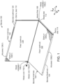
- FIG. 1 shows an example device 100 that has first and second portions 102 and 104 that are rotatably secured together by hinge assemblies 106.
- hinge assemblies 106 In the illustrated implementation, two hinge assemblies 106(1) and 106(2) are employed, but other implementations could employ a single hinge assembly or more than two hinge assemblies.
- the first portion 102 can extend from a hinge end 108 to a distal end 110.
- the second portion 104 also can extend from a hinge end 112 to a distal end 114.
- the hinge assemblies 106 can define two hinge axes 116.
- the first portion 102 can rotate around first hinge axis 116(1) and the second portion 104 can rotate around second hinge axis 116(2).
- the first portion 102 can include opposing first and second major surfaces 118 and 120 (hereinafter, first and second surfaces).
- the second portion 104 can include opposing first and second major surfaces 122 and 124 (hereinafter, first and second surfaces). (Note the second surfaces 120 and 124 are facing away from the viewer and as such are not directly visible in this view, but are shown and designated in subsequent FIGS.).
- displays 126 are supported by housing 128.
- the displays 126 can be positioned on the first and/or second surfaces 118, 120, 122, and/or 124, respectively. In the illustrated configuration, the displays 126 are positioned on first surfaces 118 and 122, respectively.
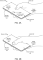
- FIGS. 2A-2D collectively show a use case scenario of device 100.
- FIG. 2A starts with device 100 in the closed orientation where the first and second portions 102 and 104 are positioned parallel to and against one another and are rotatably secured by hinge assemblies 106.
- the second surfaces are facing outwardly with the first portion's second surface 120 facing the reader and the second portion's second surface 124 facing the user's palm.
- the first surfaces are facing inwardly and first surface 122 is visible to the reader in FIG. 2C .
- the closed orientation can be very compact and easy for the user 202 to transport. For instance, the device may fit in the user's pocket. Further, the first surfaces can be protected in this closed orientation by the second surfaces.
- device 100 can also feature a user-controllable lock 204.
- the user-controllable lock 204 can function to maintain the first and second portions 102 and 104 in the closed orientation unless released by the user 202.
- the hinge assemblies 106 also include a pop-up feature that biases the first and second portions 102 and 104 away from each other from the closed orientation.
- the user 202 wants to open the device 100. For instance, the user may want to be able to view displays (126, FIG. 1 ). As shown in FIG. 2B , to open the device the user 202 can simply engage the user-controllable lock 204. In this implementation, the user can engage the user-controllable lock with a single digit (in the illustration his/her thumb) to activate the user-controllable lock and release the first and second portions 102 and 104.
- the device 100 can automatically open the first and second portions 102 and 104 a few degrees without further user effort.
- the hinge assemblies 106 provide a force that biases the first and second portions apart from the closed orientation unless the user-controllable lock maintains the closed orientation. This bias can be viewed as a ⁇ pop-up' feature. Further, once the device is popped-up, the device can maintain the orientation without user intervention (e.g., the user doesn't have to hold the device open).
- the pop-up feature can allow the user 202 to easily manually open the display 126 further if desired, and/or the user can view some or all of the displays at this point.
- a graphical user interface (GUI) 208 shows that the user has a new text message on display 126(2) that says, "Meet you at 5:00 P.M.” The user can easily view the text without further manipulation of the device portions. If the user wants to text back or perform other actions, the user can easily open the device further with one hand. In this case, assume the user is done, and can close the device 100 simply by pressing down with his/her thumb until the device is closed, and the user-controllable lock 204 re-engages as shown in FIG. 2D . Note that in this implementation, the device sensed that only a portion of the displays were visible in the pop-up orientation of FIG. 2C , and so the device customized the GUI for this orientation. A different GUI may be generated if the user opens the device to a different orientation.
- FIG. 2D shows two alternative user-controllable lock locations on the side of the device 100 as indicated at 204(1) and 204(2).
- the side locations can allow a single user-controllable lock to be accessed in both the zero-degree orientation and the 360-degree orientation.
- FIGS. 3A , 3B and 6A-8F collectively show details of example hinge assembly 106(1).
- FIG. 3A is a perspective view of example hinge assembly 106(1) and FIG.3B is an exploded view of hinge assembly 106(1) in the 180-degree orientation.
- the hinge assembly 106(1) can include a communication member 302 and hinge guides 304.
- the communication member 302 can define hinge shafts 306 that are received in apertures 308 that are defined by the hinge guides 304.
- the hinge assembly 106(1) can also include a timing element 310 that synchronizes rotation (e.g., extent of rotation) of the first and second portions 102 and 104 around the first and second hinge axes 116.
- the timing element 310 can ensure that 20 degrees of rotation around the first hinge axis 116(1) simultaneously produces 20 degrees of rotation around the second hinge axis 116(2).
- the timing element 310 can be manifest as gears.
- the hinge guides 304 can define primary gears 312 that can interact with intervening or secondary gears 314.
- the secondary gears 314 are rotatably secured relative to primary gears 312 by retainer 316.
- the communication member 302 can also receive nested inner and outer barrels 318 and 320 in a rotational relation (e.g., the inner and outer barrels are secured relative to the communication member and can rotate around the hinge axes 116.
- a conductor 322 such as traditional insulated wire(s)s and/or a flexible printed circuit(s) (FPC) can pass from portion 102 through the inner and outer barrels 318 and 320 and to the second portion 104.
- the conductor can be associated with a protective material 323.
- the protective material can provide abrasion resistance to the conductor, maintain cross-sectional integrity of the conductor (e.g., keep a rectangular conductor rectangular), and/or influence bending characteristics of the conductor to reduce pinching/binding.
- the protective material 323 is manifest as metal strips on both sides of the conductor 322.
- the conductor 322 can be retained by a cap 324, which secures to retainer 316 over the inner barrels 318, and outer barrels 320.
- Flexible covers 326 can extend between the outer barrels 320 and the conductor 322 to reduce foreign objects, such as dust and/or lint, among others, entering the hinge assembly 106(1), such as the primary and secondary gears 312 and 314.
- the hinge shafts 306 can terminate at tabs 328.
- the tabs 328 can be integral to the hinge shafts 306.
- the tabs can be on terminals 330.
- the terminals 330 can be secured to the hinge shafts 306 in a non-rotational fashion. In the illustrated example, the terminals 330 are keyed to the terminus of the hinge shafts 306 to prevent rotation. In the illustrated configuration, the terminals 330 can be secured to the hinge shafts 306 after the hinge shafts are passed through apertures 308. This configuration can allow the apertures 308 to be designed without regard to the geometry of the tabs and instead with regard to creating friction on the hinge shafts. Thus, the apertures 308 in the hinge guides 304 can act as friction cylinders on the hinge shafts 306.
- Force generating elements (e.g., biasing elements) 331, such as springs 332 can operate relative to force transferring elements 333, such as hinge guides 304 and/or pop-up arms 334.
- the springs 332 are positioned between the hinge guides 304 and the pop-up arms 334.
- Retainers 336 and 338 retain the springs 332 relative to the hinge guides 304 and the pop-up arms 334, respectively.
- the tabs 328 can include pins 340 that can be received in elongate slots 342 in the pop-up arms 334.
- the elongated slots 342 can allow relative movement between the pop-up arms 334 and the tabs 328 transverse to the hinge axes 116, but can limit relative movement in other directions.
- a retainer 344 can be positioned between the tabs 328 and the pop-up arms 334 between the elongate slots 342.
- the hinge guides 304 can be fixed to the first and second portions 102 and 104, such as by fasteners (not shown) through holes 346 (not all of which are designated with specificity) into housing 128.
- the inner barrels 318 can define guide surfaces 348 and 350.
- the guide surfaces 348 and 350 can define a path P of the conductor 322 through the hinge assembly 106(1) that maintains a minimum bend radius of the conductor during rotation of the first and second portions.
- the minimum bend radius can prevent crimping and/or other damage to the conductor during rotation of the first and second portions 102 and 104. This aspect will be described in more detail below relative to FIGS. 6D , 7D , and 8D .
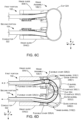
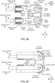
- FIGS. 4 and 5 illustrate two additional example hinge assemblies 106A and 106B.
- a majority of the elements of hinge assemblies 106A and 106B are similar to those described above relative to hinge assembly 106(1) and as such are not re-introduced or discussed here.
- the communication member 302A includes retainer 316A. Further, the communication member 302A defines brackets 402 that cooperatively interact with the inner and outer barrels 318A and 320A to define path P for the conductor 322A.
- the inner barrels 318A can define pins 404 that are received in domes 406 of the cap 324A to retain the inner barrels while allowing rotation as defined by the domes.
- FIG. 5 shows hinge assembly 106B with expanded brackets 402B.
- the brackets operate cooperatively with a single barrel 502 to define path P for the conductor 322B.
- FIGS. 6A-8F collectively show features of the hinge assembly 106(1) during rotation of the first and second portions 102 and 104 through several orientations.
- FIGS. 6A-6F show the first and second portions 102 and 104 (e.g., the hinge guides 304(1) and 304(2)) parallel to one another at a zero-degree (e.g., closed) orientation similar to FIG. 2A .
- FIG. 6A is a perspective view
- FIG. 6B is a (side) elevational view (e.g., parallel to the hinge axes 116)
- FIG. 6C is a (top) elevational view.
- FIGS. 6D-6F are sectional views as indicated in FIG. 6B .
- FIGS. 7A-7F are similar views to FIGS.
- FIGS. 8A-8F are similar views at a 180-degree (e.g. parallel) orientation. Note that while the drawings are organized by orientation, it may be helpful for the reader to also compare specific views at multiple orientations. For instance, the function of the elements shown in FIG. 6D may be understood by reviewing FIG. 6D in combination with FIGS. 7D and/or 8D.
- the guide surfaces 348 and 350, along with outer barrels 320 are defining the path P through the hinge assembly 106(1).
- guide surfaces 350(1) and 350(2) are collectively defining a minimum bend radius 'r' for the conductor 322 through the hinge assembly 106(1).
- the minimum bend radius is almost as wide as the hinge assembly 106.
- the minimum bend radius has a diameter D (e.g., 2r) that is greater than a distance or width Wi between the conductor 322 in the first and second portion 102 and 104 in this closed position.
- the relatively large minimum bend radius can protect the conductor from crimping and/or other damage as the first and second portions are rotated through a range of rotation, such as zero-degrees to 360-degrees.
- a width w 2 between guide surfaces 348(1) and 350(1) and 348(2) and 350(2) is approximately equal to a width w 3 of the conductor 322 in the hinge assembly 106(1).
- a width w 4 between cap 324 and outer barrels 320(1) and 320(2) is also approximately equal to widths w 2 and w 3 . This configuration allows the hinge assembly 106(1) to hold or cradle the conductor in place during rotation to avoid situations where the conductor slips out of the path P and gets pinched or otherwise damaged.
- path P protects the conductor 322 from damage due to twisting because in this implementation the path P is contained within a plane that is parallel to the xy-reference plane (e.g., there is no z-reference axis change along the path). Thus, the conductor is only exposed to a single axis of rotation (e.g., around the hinge axis(s)) and is not subject to twisting. Stated another way, in this implementation, path P is straight, allowing for different length management techniques of the conductor 322 through the range of motion that would not otherwise be allowed if the conductor was required to make a sharp corner adjacent to the bending location.
- flexible covers 326(2) and 326(4) are sealing between the hinge guides 304 and the outer barrels 320 to prevent debris from entering the hinge assembly 106(1).
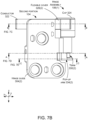
- FIG. 6E shows tabs 328 of the hinge shafts 306 engaging surfaces 602 of the pop-arms 334. This engagement is forcing the pop-up arms 334 to the left (as indicated by arrow 604). The leftward movement of the pop-up arms 334 is compressing the springs 332 and causing the springs to exert an opposing force in the opposite direction (e.g., a pop-up force).
- a pop-up force e.g., a pop-up force
- a device implementation can employ pop-up asymmetrically.
- the device might include the pop-up feature when closed at the zero-degree orientation, such as with displays facing inwardly, but not at the 360-degree orientation, such as with the displays facing outwardly, for example.
- the degree of pop-up from zero degrees could be different than from 360 degrees.
- the pop-up could be zero to 30 degrees versus 360 to 340 degrees.
- FIG. 6F shows the movement of the pop-up arms 334 relative to the hinge axes 116.
- the elongate slots 342 in the pop-up arms 334 have shifted to the left (e.g., the pins 340 (of the terminals 330 of FIG. 6E ) are positioned at the extreme right of the slots 342).
- the pop-up arms 334 have been moved to the left and are compressing springs 332.
- the slots 342 can facilitate movement of the pop-up arms 334 along the length of the slots while constraining movement of the pop arms in other directions, such as the x-reference direction. This ability to facilitate movement in one direction while constraining movement in other directions can focus the energy in the springs 332 for use as pop up torque.
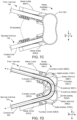
- FIGS. 7A-7F show the first and second portions 102 and 104 rotated about 30 degrees from the zero-degree orientation of FIGS. 6A-6F . Specifically, about 15 degrees of rotation has occurred around each hinge axis 116. As shown in FIG. 7D , the guide surfaces 348 and 350 are continuing to define conductor path P including the bend radius r through the hinge assembly 106(1).
- the flexible covers 326 can allow slight relative movement between the conductor 322 and the hinge assembly 106(1) while sealing between the first and second portions 102 and 104 and the hinge assembly 106(1) to prevent debris from entering the inner barrels 318 and the outer barrels 320.
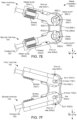
- FIGS. 7E and 7F show the rotation of the first and second portions 102 and 104 around hinge axes 116(1) and 116(2) has progressed until the springs 332 are no longer compressed. Specifically, the springs 332 have exerted a (pop-up) force on the pop-up arms 334. The pop-up arms 334 have pushed on the tabs 328 causing rotation of the first and second portions around the hinge axes. This rotation is rotating the tabs 328 away from the surfaces 602 of the pop-up arms 334. The springs 332 are forcing the pop-up arms to the right as reflected by the fact that the pins 340 have moved from the right-most extreme of the elongate slots 342 to the left-most extreme.
- the first and second portions can rotate through a range of rotations, such as from 0-360 degrees.
- the springs were imparting a pop-up force on the hinge shafts 306 to rotate the first and second portions apart.
- the first sub-range of rotation may resume, such as from 330 degrees to 360 degrees when the tabs 328 encounter surfaces 606.
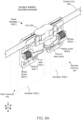
- FIGS. 8A-8F show the first and second portions 102 and 104 rotated to a 180-degree orientation with the first and second portions abutting one another (e.g., touching or with a slight gap).
- FIG. 8D shows the inner and outer barrels 318 and 320 continuing to define the path P of the conductor 322 through the hinge assembly 106(1). Note that as rotation of the first and second portions 102 and 104 has progressed from the zero-degree orientation of FIGS. 6A-6F to the 180-degree orientation that the path P has not imparted any z-axis rotation on the conductor 322. Further, flexible covers 326(1)-326(4) are blocking entry of debris into the hinge assembly 106(1) proximate to the conductor 322 (e.g., along path P).
- FIGS. 8E and 8F show the tabs 328 are not engaging surfaces 602 or 606 and the springs 332 are uncompressed in this open orientation.
- One example includes a device comprising of a first portion and a second portion that are rotatably coupled to rotate around first and second hinge axes from a closed orientation to an open orientation.
- the device can also include a first barrel positioned to rotate around the first hinge axis and defining a first guide surface and a second barrel positioned to rotate around the second hinge axis and defining a second guide surface.
- the device can also include a conductor spanning between the first and second portions along a path collectively defined by the first and second guide surfaces.
- Another example can include any of the above and/or below examples where the first barrel comprises nested first inner and first outer barrels and the second barrel comprises nested second inner and second outer barrels.
- Another example can include any of the above and/or below examples where in the closed orientation, the path defines a minimum bend radius of the conductor that is greater than one half a distance between the conductor in the first and second portions.
- Another example can include any of the above and/or below examples where in a range of rotation from the closed orientation to the open orientation, the conductor is maintained in a plane that is transverse to the first and second hinge axes.
- Another example can include any of the above and/or below examples where the device further comprises a first flexible cover extending between the first portion and the first barrel and a second flexible cover extending between the second portion and the second barrel.
- Another example can include any of the above and/or below examples where the device further comprises opposing first and second flexible covers extending between the first portion and the first barrel and opposing third and fourth flexible cover extending between the second portion and the second barrel.
- Another example can include any of the above and/or below examples where the first barrel defines a third guide surface and the second barrel defines a fourth guide surface.
- Another example can include any of the above and/or below examples where the first and second guide surfaces collectively define a first side of the path and the third and fourth guide surfaces collectively define an opposing second side of the path.
- Another example can include any of the above and/or below examples where the device further comprises a force generating element.
- Another example can include any of the above and/or below examples where the force generating element comprises a spring.
- Another example can include any of the above and/or below examples where the device further comprises a force transferring element that conveys force from the force generating element to the first and second portions for a first sub-range of rotation between the closed orientation and the open orientation, and wherein the force transferring element does not convey the force during a second sub-range of rotation.
- Another example can include any of the above and/or below examples where the first sub-range of rotation is zero-degrees to 30-degrees and 331-degrees to 360-degrees and wherein the second sub-range of rotation is 31-degrees to 330-degrees.
- Another example can include any of the above and/or below examples where the force transferring element comprises a pop-up arm.
- Another example can include any of the above and/or below examples where the force transferring element comprises a first pop-up arm that operates relative to the first hinge axis and a second pop-up arm that operates relative to the second hinge axis.
- Another example can include any of the above and/or below examples where the device further comprises a communication member that defines first and second hinge shafts that extend along the first and second hinge axes.
- Another example can include any of the above and/or below examples where the first hinge shaft defines a first tab and the second hinge shaft defines a second tab.
- Another example can include any of the above and/or below examples where engagement between the first tab and the pop-up arm and engagement between the second tab and the second pop-up arm creates the force in the first sub-range of rotation.
- Another example can include a device comprising of a first portion and a second portion that are rotatably coupled via a hinge shaft that includes a tab extending orthogonally from the hinge shaft.
- the device can also include a spring.
- the device can also comprise of a force transferring element extending between the spring and the tab and compressing the spring when engaging the tab and thereby creating a force to rotate the first and second portions away from one another.
- Another example can include any of the above and/or below examples where the force transferring element comprises a pop-up arm.
- Another example can include a device comprising of a hinge assembly that rotatably secures a first portion and a second portion relative to a hinge axis and defines a planar conductor path between the first and second portions through the hinge assembly and a pop-up arm that compresses a spring when the first portion and the second portion are rotated to a closed orientation, and wherein the compressed spring creates a bias to rotate the first and second portions from the closed orientation to an open orientation.
- Individual elements of the hinge assemblies can be made from various materials, such as metals, plastics, and/or composites. These materials can be prepared in various ways, such as in the form of sheet metals, die cast metals, machined metals, 3D printed materials, molded or 3D printed plastics, and/or molded or 3D printed composites, among others, and/or any combination of these materials and/or preparations can be employed.
- the present hinge assembly concepts can be utilized with any type of device, such as but not limited to notebook computers, smart phones, wearable smart devices, tablets, and/or other types of existing, developing, and/or yet to be developed devices.
- hinge assemblies and devices are contemplated beyond those shown above relative to FIGS. 1-8F .
Landscapes
- Engineering & Computer Science (AREA)
- Computer Hardware Design (AREA)
- Theoretical Computer Science (AREA)
- General Engineering & Computer Science (AREA)
- Mechanical Engineering (AREA)
- Physics & Mathematics (AREA)
- Human Computer Interaction (AREA)
- General Physics & Mathematics (AREA)
- Computer Networks & Wireless Communication (AREA)
- Signal Processing (AREA)
- Mathematical Physics (AREA)
- Casings For Electric Apparatus (AREA)
Claims (10)
- Vorrichtung, umfassend:einen ersten Abschnitt (102) und einen zweiten Abschnitt (104), die drehbar gekoppelt sind, um sich mittels einer Scharnieranordnung (106) um erste und zweite Scharnierachsen (116(1), 116(2)) aus einer geschlossenen Ausrichtung, in der der erste und zweite Abschnitt (102, 104) parallel zueinander und aneinanderliegend positioniert sind, in eine offene Ausrichtung zu drehen; undeinen Leiter (322), der eine Breite (w3) aufweist;wobei die Scharnieranordnung (106) umfasst:ein Verbindungselement (302) und Scharnierführungen (304),verschachtelte erste innere und erste äußere Zylinder (318(1), 320(1)), die an dem Verbindungselement (302) befestigt und so konfiguriert sind, dass sie sich um die erste Scharnierachse (116(1)) drehen, wobei der erste innere Zylinder (318(1)) eine erste Führungsfläche (348(1)) und eine zweite Führungsfläche (350(1)) mit einer Breite (w2) dazwischen zum Halten des Leiters (322) definiert,verschachtelte zweite innere und zweite äußere Zylinder (318(2), 320(2)), die an dem Verbindungselement (302) befestigt und so konfiguriert sind, dass sie sich um die zweite Scharnierachse (116(2)) drehen, und wobei der zweite innere Zylinder (318(2)) eine dritte Führungsfläche (348(2)) und eine vierte Führungsfläche (350(2)) mit einer Breite (w2) dazwischen zum Halten des Leiters (322) definiert; undeine Kappe (324), die an einem Halter (316) über dem ersten und zweiten inneren Zylinder und dem ersten und zweiten äußeren Zylinder befestigt ist, wobei die Kappe von den äußeren Zylindern um eine Breite (w4) beabstandet ist, wobei die Kappe (324) so konfiguriert ist, dass sie den Leiter (322) zurückhält;wobei der Leiter (322) sich zwischen dem ersten und zweiten Abschnitt (102, 104) entlang eines Pfads (P) durch den ersten und zweiten inneren und äußeren Zylinder (318, 320) erstreckt, wobei der Pfad (P) gemeinsam durch den ersten und zweiten äußeren Zylinder (320(1), (320(2)) und die erste, zweite, dritte und vierte Führungsfläche (348(1), 350(1), 348(2), 350(2)) definiert wird;wobei die Breite (w3) des Leiters (322), die Breite (w2) zwischen der ersten und zweiten Führungsfläche (348(1), 350(1)), die Breite (w2) zwischen der dritten und vierten Führungsfläche (348(2), 350(2)) und die Breite (w4) zwischen der Kappe und den äußeren Zylindern ungefähr gleich sind, sodass die Scharnieranordnung den Leiter während der Drehung an seinem Platz hält;wobei in der geschlossenen Ausrichtung der Pfad (P) einen minimalen Biegeradius des Leiters (322) definiert, der größer ist als eine halbe Distanz zwischen dem Leiter (322) in dem ersten und zweiten Abschnitt (102, 104); undwobei der Pfad (P) so konfiguriert ist, dass der Leiter (322) in einem Drehbereich von der geschlossenen Ausrichtung zur offenen Ausrichtung in einer Ebene beibehalten wird, die quer zu der ersten und zweiten Scharnierachse (116(1), 116(2)) verläuft.
- Vorrichtung, umfassend:einen ersten Abschnitt (102) und einen zweiten Abschnitt (104), die drehbar gekoppelt sind, um sich mittels einer Scharnieranordnung (106B) um erste und zweite Scharnierachsen (116(1), 116(2)) aus einer geschlossenen Ausrichtung, in der der erste und zweite Abschnitt (102, 104) parallel zueinander und aneinanderliegend positioniert sind, in eine offene Ausrichtung zu drehen; undeinen Leiter (322B), der eine Breite (w3) aufweist;wobei die Scharnieranordnung (106B) umfasst:ein Verbindungselement (302) und Scharnierführungen (304), wobei das Verbindungselement einen Halter (316A) beinhaltet und erste und zweite Klammern (402B(1), 402B(2)) definiert;einen ersten Zylinder (502(1)), der an dem Verbindungselement (302A) befestigt und so konfiguriert ist, dass er sich um die erste Scharnierachse (116(1)) dreht, wobei der erste Zylinder (502(1)) eine erste Führungsfläche (348A(1)) und eine zweite Führungsfläche (350A(1)) mit einer Breite (w2) dazwischen zum Halten des Leiters (322) definiert;einen zweiten Zylinder (502(2)), der an dem Verbindungselement (302A) befestigt und so konfiguriert ist, dass er sich um die zweiten Scharnierachse (116(2)) dreht und eine dritte Führungsfläche (350A(2)) und eine vierte Führungsfläche (350A(2)) mit einer Breite (w2) dazwischen zum Halten des Leiters (322) definiert; undeine Kappe (324), die an einem Halter (316) über dem ersten und zweiten Zylinder befestigt ist, wobei die Kappe von den Klammern um eine Breite (w4) beabstandet ist, wobei die Kappe (324) so konfiguriert ist, dass sie den Leiter (322) zurückhält;wobei der Leiter (322) sich zwischen dem ersten und zweiten Abschnitt entlang eines Pfads (P) erstreckt, der gemeinsam durch erste und zweite Klammern (402B(1), 402B(2)) und die erste, zweite, dritte und vierte Führungsfläche definiert wird;wobei die Breite (w3) des Leiters (322), die Breite (w2) zwischen der ersten und zweiten Führungsfläche (348(1), 350(1)), die Breite (w2) zwischen der dritten und vierten Führungsfläche (348(2), 350(2)) und die Breite (w4) zwischen der Kappe und den Klammern ungefähr gleich sind, sodass die Scharnieranordnung den Leiter während der Drehung an seinem Platz hält;wobei in der geschlossenen Ausrichtung der Pfad (P) einen minimalen Biegeradius des Leiters (322) definiert, der größer ist als eine halbe Distanz zwischen dem Leiter (322) in dem ersten und zweiten Abschnitt (102, 104); undwobei der Pfad (P) so konfiguriert ist, dass der Leiter (322) in einem Drehbereich von der geschlossenen Ausrichtung zur offenen Ausrichtung in einer Ebene beibehalten wird, die quer zu der ersten und zweiten Scharnierachse (116(1), 116(2)) verläuft.
- Vorrichtung nach Anspruch 1, ferner umfassend eine erste flexible Abdeckung (326(1)), die sich zwischen dem ersten Abschnitt (102) und den ersten inneren und äußeren Zylindern (318(1), 320(1)) erstreckt, und eine zweite flexible Abdeckung (326(2)), die sich zwischen dem zweiten Abschnitt und den zweiten inneren und äußeren Zylindern (318(2), 320(2)) erstreckt.
- Vorrichtung nach Anspruch 1, ferner umfassend gegenüberliegende erste und zweite flexible Abdeckungen (326(2), 326(4)), die sich zwischen dem ersten Abschnitt (102) und den verschachtelten ersten inneren und äußeren Zylindern (318(1), 320(1)) und gegenüberliegenden dritten und vierten flexiblen Abdeckungen (326(1), 326(3)) erstrecken, die sich zwischen dem zweiten Abschnitt (104) und den verschachtelten zweiten inneren und äußeren Zylindern (318(1), 320(1)) erstrecken.
- Vorrichtung nach Anspruch 1 oder Anspruch 2, ferner umfassend ein Krafterzeugungselement (331).
- Vorrichtung nach Anspruch 5, wobei das Krafterzeugungselement (331) eine Feder (332) umfasst.
- Vorrichtung nach Anspruch 5, ferner umfassend ein Kraftübertragungselement (333), das so konfiguriert ist, dass es für einen ersten Unterdrehbereich zwischen der geschlossenen Ausrichtung und der offenen Ausrichtung Kraft von dem Krafterzeugungselement (331) an den ersten und zweiten Abschnitt (102, 104) übermittelt, und wobei das Kraftübertragungselement (333) die Kraft während eines zweiten Unterdrehbereichs nicht übermittelt.
- Vorrichtung nach Anspruch 7, wobei der erste Unterdrehbereich Null Grad bis 30 Grad und 331 Grad bis 360 Grad beträgt und wobei der zweite Unterdrehbereich 31 Grad bis 330 Grad beträgt.
- Vorrichtung nach Anspruch 7, wobei das Kraftübertragungselement (333) einen Pop-up-Arm (334) umfasst.
- Vorrichtung nach Anspruch 7, wobei das Kraftübertragungselement (333) einen ersten Pop-up-Arm (334), der so konfiguriert ist, dass er relativ zu der ersten Scharnierachse (116(1)) arbeitet, und einen zweiten Pop-up-Arm (334) umfasst, der so konfiguriert ist, dass er relativ zu der zweiten Scharnierachse arbeitet.
Applications Claiming Priority (2)
| Application Number | Priority Date | Filing Date | Title |
|---|---|---|---|
| US15/713,449 US10795416B2 (en) | 2017-09-22 | 2017-09-22 | Hinged device |
| PCT/US2018/039217 WO2019060011A1 (en) | 2017-09-22 | 2018-06-25 | ARTICULATED DEVICE |
Publications (2)
| Publication Number | Publication Date |
|---|---|
| EP3673341A1 EP3673341A1 (de) | 2020-07-01 |
| EP3673341B1 true EP3673341B1 (de) | 2024-11-06 |
Family
ID=62986185
Family Applications (1)
| Application Number | Title | Priority Date | Filing Date |
|---|---|---|---|
| EP18743907.0A Active EP3673341B1 (de) | 2017-09-22 | 2018-06-25 | Scharniervorrichtung |
Country Status (3)
| Country | Link |
|---|---|
| US (1) | US10795416B2 (de) |
| EP (1) | EP3673341B1 (de) |
| WO (1) | WO2019060011A1 (de) |
Families Citing this family (30)
| Publication number | Priority date | Publication date | Assignee | Title |
|---|---|---|---|---|
| US10474203B2 (en) | 2016-09-01 | 2019-11-12 | Microsoft Technology Licensing, Llc | Hinged device |
| US10364598B2 (en) | 2016-09-02 | 2019-07-30 | Microsoft Technology Licensing, Llc | Hinged device |
| US10641318B2 (en) * | 2016-12-09 | 2020-05-05 | Microsoft Technology Licensing, Llc | Hinged device |
| US10754377B2 (en) | 2017-04-05 | 2020-08-25 | Microsoft Technology Licensing, Llc | Hinged device |
| US10344510B2 (en) | 2017-06-16 | 2019-07-09 | Microsoft Technology Licensing, Llc | Hinged device |
| US10571977B2 (en) * | 2017-12-26 | 2020-02-25 | Intel Corporation | Technologies for hinges for dual screen devices |
| US11091944B2 (en) * | 2018-03-28 | 2021-08-17 | Microsoft Technology Licensing, Llc | Hinged device |
| TWI673545B (zh) * | 2018-06-21 | 2019-10-01 | 兆利科技工業股份有限公司 | 折疊式裝置的轉軸模組 |
| US11181950B2 (en) * | 2018-07-24 | 2021-11-23 | Microsoft Technology Licensing, Llc | Hinged device |
| US10787846B2 (en) * | 2018-08-03 | 2020-09-29 | General Electric Company | Additively manufactured hinge assembly |
| USD962920S1 (en) * | 2019-01-07 | 2022-09-06 | Compal Electronics, Inc. | Notebook computer with liftable display |
| USD965585S1 (en) * | 2019-01-07 | 2022-10-04 | Compal Electronics, Inc. | Notebook computer with liftable display |
| USD965586S1 (en) * | 2019-01-07 | 2022-10-04 | Compal Electronics, Inc. | Notebook computer with liftable display |
| KR102576840B1 (ko) * | 2019-02-19 | 2023-09-12 | 삼성전자주식회사 | 힌지 모듈 및 이를 포함하는 접이식 디스플레이 장치 |
| US10761572B1 (en) | 2019-03-25 | 2020-09-01 | Microsoft Technology Licensing, Llc | Hinged device |
| KR102798966B1 (ko) * | 2019-04-01 | 2025-04-24 | 삼성디스플레이 주식회사 | 전자 장치 |
| US11106248B2 (en) * | 2019-04-10 | 2021-08-31 | Microsoft Technology Licensing, Llc | Hinged device |
| US10545541B1 (en) * | 2019-05-06 | 2020-01-28 | Microsoft Technology Licensing, Llc | Hinged device |
| US11353931B2 (en) * | 2019-06-27 | 2022-06-07 | Jarlly Tec Co., Ltd. | Hinge device for a foldable device |
| US11219135B2 (en) * | 2019-10-01 | 2022-01-04 | Microsoft Technology Licensing, Llc | Impact resistant hinge |
| KR102222181B1 (ko) * | 2020-01-22 | 2021-03-04 | 박수철 | 폴딩도어의 힌지 조립체 |
| US11720151B2 (en) | 2020-08-03 | 2023-08-08 | Microsoft Technology Licensing, Llc | Hinged device |
| US11567543B2 (en) * | 2020-09-29 | 2023-01-31 | Microsoft Technology Licensing, Llc | Hinge assembly for mobile computing device |
| US11669132B2 (en) * | 2020-09-29 | 2023-06-06 | Microsoft Technology Licensing, Llc | Hinge assembly for mobile computing device |
| US11599159B2 (en) * | 2021-05-25 | 2023-03-07 | Microsoft Technology Licensing, Llc | Sliding double-pivot hinge |
| KR20230049264A (ko) | 2021-10-06 | 2023-04-13 | 삼성전자주식회사 | 힌지 모듈을 포함하는 전자 장치 |
| US11720144B2 (en) * | 2021-11-29 | 2023-08-08 | Microsoft Technology Licensing, Llc | Hinged device |
| US12181916B2 (en) | 2022-10-13 | 2024-12-31 | Microsoft Technology Licensing, Llc | Device push-to-open detection and power control |
| EP4461158A1 (de) * | 2023-05-10 | 2024-11-13 | ULTIMATE Europe Transportation Equipment GmbH | Scharnier |
| US20260104742A1 (en) * | 2024-10-15 | 2026-04-16 | Microsoft Technology Licensing, Llc | Hinged Device |
Family Cites Families (24)
| Publication number | Priority date | Publication date | Assignee | Title |
|---|---|---|---|---|
| US4004771A (en) * | 1972-09-09 | 1977-01-25 | Gewerkschaft Eisenhutte Westfalia | Ball-and-socket type connections for use with mining apparatus |
| DE3613574A1 (de) * | 1986-04-22 | 1987-12-23 | Theodor Puschkarski | Verbindungselement zum verbinden zweier platten |
| FR2746151B1 (fr) * | 1996-03-15 | 1998-05-22 | Dispositif de protection et de guidage d'un composant allonge associe, au niveau de l'articulation, a deux elements rigides articules l'un a l'autre, et ses applications industrielles | |
| US7054147B2 (en) * | 2003-09-11 | 2006-05-30 | Nokia Corporation | Double articulated hinge mechanism for electronic devices |
| TWI250764B (en) * | 2004-05-14 | 2006-03-01 | Benq Corp | Hinge connector for folding-type electronic apparatus |
| US7414834B2 (en) * | 2005-04-21 | 2008-08-19 | Nokia Corporation | Mobile communications device with synchronising hinge |
| CN1959135B (zh) * | 2005-11-04 | 2011-06-29 | 深圳富泰宏精密工业有限公司 | 铰链结构及应用该铰链结构的折叠式电子装置 |
| KR100653212B1 (ko) * | 2005-11-17 | 2006-12-05 | 주식회사 팬택 | 폴더형 힌지장치 및 폴더형 힌지장치를 사용한개인휴대단말기 |
| US7667959B2 (en) * | 2005-12-20 | 2010-02-23 | Nokia Corp. | Foldable electronic device having double-axis hinge and locking spring |
| US7593524B2 (en) * | 2006-11-27 | 2009-09-22 | Nokia Corporation | Hinge arrangement |
| US20120011683A9 (en) * | 2008-02-29 | 2012-01-19 | Kim David K J | Routing flexible printed circuit board through hinge of electronic device |
| ITMI20082355A1 (it) * | 2008-12-30 | 2010-06-30 | Guido Medana | Sistema di vincolo per l'assemblaggio di occhiali ed occhiali ottenuti con tale sistema. |
| US7886406B2 (en) * | 2009-01-22 | 2011-02-15 | Chao-Ming Chang | Hinge device having two back-to-back interconnected C-shaped clamps |
| US8593800B2 (en) * | 2009-11-05 | 2013-11-26 | Panasonic Corporation | Electronic equipment with hinge mechanism |
| US8660621B2 (en) | 2010-08-20 | 2014-02-25 | Blackberry Limited | Mobile phone |
| CN102609036A (zh) * | 2011-01-24 | 2012-07-25 | 鸿富锦精密工业(深圳)有限公司 | 便携式电子装置 |
| US9535465B2 (en) * | 2011-02-10 | 2017-01-03 | Microsoft Technology Licensing, Llc | Hinge electrical interconnection guide |
| US8773849B2 (en) * | 2011-04-11 | 2014-07-08 | Microsoft Corporation | Extendable connecting link |
| JP6079630B2 (ja) * | 2011-09-21 | 2017-02-15 | 日本電気株式会社 | 電子機器 |
| DE102013108083B3 (de) * | 2013-07-29 | 2014-05-15 | Simonswerk, Gesellschaft mit beschränkter Haftung | Verdeckt liegendes Türband mit elektrischer Verbindung |
| US10253804B2 (en) * | 2017-01-24 | 2019-04-09 | Microsoft Technology Licensing, Llc | Hinged device |
| KR102426694B1 (ko) * | 2017-05-02 | 2022-07-29 | 삼성전자주식회사 | 플렉서블 디스플레이를 포함하는 전자 장치 |
| US10296044B2 (en) * | 2017-06-08 | 2019-05-21 | Microsoft Technology Licensing, Llc | Hinged device |
| US10344510B2 (en) * | 2017-06-16 | 2019-07-09 | Microsoft Technology Licensing, Llc | Hinged device |
-
2017
- 2017-09-22 US US15/713,449 patent/US10795416B2/en active Active
-
2018
- 2018-06-25 WO PCT/US2018/039217 patent/WO2019060011A1/en not_active Ceased
- 2018-06-25 EP EP18743907.0A patent/EP3673341B1/de active Active
Also Published As
| Publication number | Publication date |
|---|---|
| US20190094917A1 (en) | 2019-03-28 |
| US10795416B2 (en) | 2020-10-06 |
| EP3673341A1 (de) | 2020-07-01 |
| WO2019060011A1 (en) | 2019-03-28 |
Similar Documents
| Publication | Publication Date | Title |
|---|---|---|
| EP3673341B1 (de) | Scharniervorrichtung | |
| EP3756064B1 (de) | Scharniervorrichtung | |
| CN110494819B (zh) | 铰接设备 | |
| CN107533822B (zh) | 柔性屏组件及终端 | |
| US7193653B2 (en) | Camera lens assembly and portable wireless terminal comprising the same | |
| JP2914923B2 (ja) | ポインティング・デバイスを有する小型電子機器 | |
| CN101341455B (zh) | 具有双轴线铰链的可折叠电子设备及铰链 | |
| WO2019120167A1 (zh) | 转动机构及折叠终端 | |
| US20050225093A1 (en) | Automatic opening and closing hinge assembly for portable electronic devices | |
| JP2004328279A (ja) | 携帯端末機 | |
| CN111749974B (zh) | 锁释机构、开合装置和电子设备 | |
| US20090260183A1 (en) | Hinge assembly for foldable electronic devices | |
| US7822447B2 (en) | Push rod and sliding type portable terminal having the same | |
| US7027846B2 (en) | Clam-shaped electronic device and hinge mechanism thereof | |
| US7334297B2 (en) | Hinge assembly for foldable electronic device | |
| CN106450651B (zh) | 一种电子设备及其连接轴、天线实现方法 | |
| US20030234988A1 (en) | Hand-held electronic appliance | |
| JP4733678B2 (ja) | 携帯機器 | |
| US7401381B2 (en) | Folding mechanism | |
| US8478368B2 (en) | Portable electronic device | |
| CN107589781A (zh) | 支撑脚架与携带型电子装置 | |
| US20040106314A1 (en) | Portable apparatus with inward-pushing triggered mechanism for ejecting add-on device | |
| CN111654605B (zh) | 摄像头模组及电子设备 | |
| JPH077274A (ja) | 携帯形小型装置 | |
| WO2024021890A1 (zh) | 支撑装置、壳体及电子设备 |
Legal Events
| Date | Code | Title | Description |
|---|---|---|---|
| STAA | Information on the status of an ep patent application or granted ep patent |
Free format text: STATUS: UNKNOWN |
|
| STAA | Information on the status of an ep patent application or granted ep patent |
Free format text: STATUS: THE INTERNATIONAL PUBLICATION HAS BEEN MADE |
|
| PUAI | Public reference made under article 153(3) epc to a published international application that has entered the european phase |
Free format text: ORIGINAL CODE: 0009012 |
|
| STAA | Information on the status of an ep patent application or granted ep patent |
Free format text: STATUS: REQUEST FOR EXAMINATION WAS MADE |
|
| 17P | Request for examination filed |
Effective date: 20200327 |
|
| AK | Designated contracting states |
Kind code of ref document: A1 Designated state(s): AL AT BE BG CH CY CZ DE DK EE ES FI FR GB GR HR HU IE IS IT LI LT LU LV MC MK MT NL NO PL PT RO RS SE SI SK SM TR |
|
| AX | Request for extension of the european patent |
Extension state: BA ME |
|
| DAV | Request for validation of the european patent (deleted) | ||
| DAX | Request for extension of the european patent (deleted) | ||
| STAA | Information on the status of an ep patent application or granted ep patent |
Free format text: STATUS: EXAMINATION IS IN PROGRESS |
|
| 17Q | First examination report despatched |
Effective date: 20210608 |
|
| RAP3 | Party data changed (applicant data changed or rights of an application transferred) |
Owner name: MICROSOFT TECHNOLOGY LICENSING, LLC |
|
| GRAP | Despatch of communication of intention to grant a patent |
Free format text: ORIGINAL CODE: EPIDOSNIGR1 |
|
| STAA | Information on the status of an ep patent application or granted ep patent |
Free format text: STATUS: GRANT OF PATENT IS INTENDED |
|
| INTG | Intention to grant announced |
Effective date: 20240712 |
|
| GRAS | Grant fee paid |
Free format text: ORIGINAL CODE: EPIDOSNIGR3 |
|
| GRAA | (expected) grant |
Free format text: ORIGINAL CODE: 0009210 |
|
| STAA | Information on the status of an ep patent application or granted ep patent |
Free format text: STATUS: THE PATENT HAS BEEN GRANTED |
|
| AK | Designated contracting states |
Kind code of ref document: B1 Designated state(s): AL AT BE BG CH CY CZ DE DK EE ES FI FR GB GR HR HU IE IS IT LI LT LU LV MC MK MT NL NO PL PT RO RS SE SI SK SM TR |
|
| REG | Reference to a national code |
Ref country code: GB Ref legal event code: FG4D |
|
| REG | Reference to a national code |
Ref country code: CH Ref legal event code: EP |
|
| P01 | Opt-out of the competence of the unified patent court (upc) registered |
Free format text: CASE NUMBER: APP_55807/2024 Effective date: 20241011 |
|
| REG | Reference to a national code |
Ref country code: DE Ref legal event code: R096 Ref document number: 602018076266 Country of ref document: DE |
|
| REG | Reference to a national code |
Ref country code: IE Ref legal event code: FG4D |
|
| REG | Reference to a national code |
Ref country code: LT Ref legal event code: MG9D |
|
| REG | Reference to a national code |
Ref country code: NL Ref legal event code: MP Effective date: 20241106 |
|
| PG25 | Lapsed in a contracting state [announced via postgrant information from national office to epo] |
Ref country code: IS Free format text: LAPSE BECAUSE OF FAILURE TO SUBMIT A TRANSLATION OF THE DESCRIPTION OR TO PAY THE FEE WITHIN THE PRESCRIBED TIME-LIMIT Effective date: 20250306 Ref country code: PT Free format text: LAPSE BECAUSE OF FAILURE TO SUBMIT A TRANSLATION OF THE DESCRIPTION OR TO PAY THE FEE WITHIN THE PRESCRIBED TIME-LIMIT Effective date: 20250306 Ref country code: HR Free format text: LAPSE BECAUSE OF FAILURE TO SUBMIT A TRANSLATION OF THE DESCRIPTION OR TO PAY THE FEE WITHIN THE PRESCRIBED TIME-LIMIT Effective date: 20241106 |
|
| PG25 | Lapsed in a contracting state [announced via postgrant information from national office to epo] |
Ref country code: FI Free format text: LAPSE BECAUSE OF FAILURE TO SUBMIT A TRANSLATION OF THE DESCRIPTION OR TO PAY THE FEE WITHIN THE PRESCRIBED TIME-LIMIT Effective date: 20241106 Ref country code: NL Free format text: LAPSE BECAUSE OF FAILURE TO SUBMIT A TRANSLATION OF THE DESCRIPTION OR TO PAY THE FEE WITHIN THE PRESCRIBED TIME-LIMIT Effective date: 20241106 |
|
| REG | Reference to a national code |
Ref country code: AT Ref legal event code: MK05 Ref document number: 1740061 Country of ref document: AT Kind code of ref document: T Effective date: 20241106 |
|
| PG25 | Lapsed in a contracting state [announced via postgrant information from national office to epo] |
Ref country code: BG Free format text: LAPSE BECAUSE OF FAILURE TO SUBMIT A TRANSLATION OF THE DESCRIPTION OR TO PAY THE FEE WITHIN THE PRESCRIBED TIME-LIMIT Effective date: 20241106 |
|
| PG25 | Lapsed in a contracting state [announced via postgrant information from national office to epo] |
Ref country code: ES Free format text: LAPSE BECAUSE OF FAILURE TO SUBMIT A TRANSLATION OF THE DESCRIPTION OR TO PAY THE FEE WITHIN THE PRESCRIBED TIME-LIMIT Effective date: 20241106 |
|
| PG25 | Lapsed in a contracting state [announced via postgrant information from national office to epo] |
Ref country code: NO Free format text: LAPSE BECAUSE OF FAILURE TO SUBMIT A TRANSLATION OF THE DESCRIPTION OR TO PAY THE FEE WITHIN THE PRESCRIBED TIME-LIMIT Effective date: 20250206 |
|
| PG25 | Lapsed in a contracting state [announced via postgrant information from national office to epo] |
Ref country code: GR Free format text: LAPSE BECAUSE OF FAILURE TO SUBMIT A TRANSLATION OF THE DESCRIPTION OR TO PAY THE FEE WITHIN THE PRESCRIBED TIME-LIMIT Effective date: 20250207 Ref country code: LV Free format text: LAPSE BECAUSE OF FAILURE TO SUBMIT A TRANSLATION OF THE DESCRIPTION OR TO PAY THE FEE WITHIN THE PRESCRIBED TIME-LIMIT Effective date: 20241106 Ref country code: AT Free format text: LAPSE BECAUSE OF FAILURE TO SUBMIT A TRANSLATION OF THE DESCRIPTION OR TO PAY THE FEE WITHIN THE PRESCRIBED TIME-LIMIT Effective date: 20241106 |
|
| PG25 | Lapsed in a contracting state [announced via postgrant information from national office to epo] |
Ref country code: PL Free format text: LAPSE BECAUSE OF FAILURE TO SUBMIT A TRANSLATION OF THE DESCRIPTION OR TO PAY THE FEE WITHIN THE PRESCRIBED TIME-LIMIT Effective date: 20241106 |
|
| PG25 | Lapsed in a contracting state [announced via postgrant information from national office to epo] |
Ref country code: RS Free format text: LAPSE BECAUSE OF FAILURE TO SUBMIT A TRANSLATION OF THE DESCRIPTION OR TO PAY THE FEE WITHIN THE PRESCRIBED TIME-LIMIT Effective date: 20250206 |
|
| PG25 | Lapsed in a contracting state [announced via postgrant information from national office to epo] |
Ref country code: SM Free format text: LAPSE BECAUSE OF FAILURE TO SUBMIT A TRANSLATION OF THE DESCRIPTION OR TO PAY THE FEE WITHIN THE PRESCRIBED TIME-LIMIT Effective date: 20241106 |
|
| PGFP | Annual fee paid to national office [announced via postgrant information from national office to epo] |
Ref country code: DE Payment date: 20250520 Year of fee payment: 8 |
|
| PG25 | Lapsed in a contracting state [announced via postgrant information from national office to epo] |
Ref country code: DK Free format text: LAPSE BECAUSE OF FAILURE TO SUBMIT A TRANSLATION OF THE DESCRIPTION OR TO PAY THE FEE WITHIN THE PRESCRIBED TIME-LIMIT Effective date: 20241106 |
|
| PGFP | Annual fee paid to national office [announced via postgrant information from national office to epo] |
Ref country code: GB Payment date: 20250520 Year of fee payment: 8 |
|
| PG25 | Lapsed in a contracting state [announced via postgrant information from national office to epo] |
Ref country code: EE Free format text: LAPSE BECAUSE OF FAILURE TO SUBMIT A TRANSLATION OF THE DESCRIPTION OR TO PAY THE FEE WITHIN THE PRESCRIBED TIME-LIMIT Effective date: 20241106 |
|
| PG25 | Lapsed in a contracting state [announced via postgrant information from national office to epo] |
Ref country code: RO Free format text: LAPSE BECAUSE OF FAILURE TO SUBMIT A TRANSLATION OF THE DESCRIPTION OR TO PAY THE FEE WITHIN THE PRESCRIBED TIME-LIMIT Effective date: 20241106 |
|
| PG25 | Lapsed in a contracting state [announced via postgrant information from national office to epo] |
Ref country code: SK Free format text: LAPSE BECAUSE OF FAILURE TO SUBMIT A TRANSLATION OF THE DESCRIPTION OR TO PAY THE FEE WITHIN THE PRESCRIBED TIME-LIMIT Effective date: 20241106 |
|
| PG25 | Lapsed in a contracting state [announced via postgrant information from national office to epo] |
Ref country code: CZ Free format text: LAPSE BECAUSE OF FAILURE TO SUBMIT A TRANSLATION OF THE DESCRIPTION OR TO PAY THE FEE WITHIN THE PRESCRIBED TIME-LIMIT Effective date: 20241106 |
|
| PG25 | Lapsed in a contracting state [announced via postgrant information from national office to epo] |
Ref country code: IT Free format text: LAPSE BECAUSE OF FAILURE TO SUBMIT A TRANSLATION OF THE DESCRIPTION OR TO PAY THE FEE WITHIN THE PRESCRIBED TIME-LIMIT Effective date: 20241106 |
|
| REG | Reference to a national code |
Ref country code: DE Ref legal event code: R097 Ref document number: 602018076266 Country of ref document: DE |
|
| PG25 | Lapsed in a contracting state [announced via postgrant information from national office to epo] |
Ref country code: SE Free format text: LAPSE BECAUSE OF FAILURE TO SUBMIT A TRANSLATION OF THE DESCRIPTION OR TO PAY THE FEE WITHIN THE PRESCRIBED TIME-LIMIT Effective date: 20241106 |
|
| PLBE | No opposition filed within time limit |
Free format text: ORIGINAL CODE: 0009261 |
|
| STAA | Information on the status of an ep patent application or granted ep patent |
Free format text: STATUS: NO OPPOSITION FILED WITHIN TIME LIMIT |
|
| 26N | No opposition filed |
Effective date: 20250807 |
|
| REG | Reference to a national code |
Ref country code: CH Ref legal event code: H13 Free format text: ST27 STATUS EVENT CODE: U-0-0-H10-H13 (AS PROVIDED BY THE NATIONAL OFFICE) Effective date: 20260127 |
|
| PG25 | Lapsed in a contracting state [announced via postgrant information from national office to epo] |
Ref country code: MC Free format text: LAPSE BECAUSE OF FAILURE TO SUBMIT A TRANSLATION OF THE DESCRIPTION OR TO PAY THE FEE WITHIN THE PRESCRIBED TIME-LIMIT Effective date: 20241106 |
|
| PG25 | Lapsed in a contracting state [announced via postgrant information from national office to epo] |
Ref country code: LU Free format text: LAPSE BECAUSE OF NON-PAYMENT OF DUE FEES Effective date: 20250625 |
|
| REG | Reference to a national code |
Ref country code: BE Ref legal event code: MM Effective date: 20250630 |
|
| PG25 | Lapsed in a contracting state [announced via postgrant information from national office to epo] |
Ref country code: IE Free format text: LAPSE BECAUSE OF NON-PAYMENT OF DUE FEES Effective date: 20250625 |
|
| PG25 | Lapsed in a contracting state [announced via postgrant information from national office to epo] |
Ref country code: BE Free format text: LAPSE BECAUSE OF NON-PAYMENT OF DUE FEES Effective date: 20250630 |
|
| PG25 | Lapsed in a contracting state [announced via postgrant information from national office to epo] |
Ref country code: FR Free format text: LAPSE BECAUSE OF NON-PAYMENT OF DUE FEES Effective date: 20250630 |
|
| PG25 | Lapsed in a contracting state [announced via postgrant information from national office to epo] |
Ref country code: CH Free format text: LAPSE BECAUSE OF NON-PAYMENT OF DUE FEES Effective date: 20250630 |