EP3672902B1 - Dispositif pour le remplissage d'un récipient - Google Patents
Dispositif pour le remplissage d'un récipient Download PDFInfo
- Publication number
- EP3672902B1 EP3672902B1 EP18759619.2A EP18759619A EP3672902B1 EP 3672902 B1 EP3672902 B1 EP 3672902B1 EP 18759619 A EP18759619 A EP 18759619A EP 3672902 B1 EP3672902 B1 EP 3672902B1
- Authority
- EP
- European Patent Office
- Prior art keywords
- filling
- container
- carrier
- valve
- bolt
- Prior art date
- Legal status (The legal status is an assumption and is not a legal conclusion. Google has not performed a legal analysis and makes no representation as to the accuracy of the status listed.)
- Active
Links
Images


Classifications
-
- B—PERFORMING OPERATIONS; TRANSPORTING
- B67—OPENING, CLOSING OR CLEANING BOTTLES, JARS OR SIMILAR CONTAINERS; LIQUID HANDLING
- B67C—CLEANING, FILLING WITH LIQUIDS OR SEMILIQUIDS, OR EMPTYING, OF BOTTLES, JARS, CANS, CASKS, BARRELS, OR SIMILAR CONTAINERS, NOT OTHERWISE PROVIDED FOR; FUNNELS
- B67C3/00—Bottling liquids or semiliquids; Filling jars or cans with liquids or semiliquids using bottling or like apparatus; Filling casks or barrels with liquids or semiliquids
- B67C3/02—Bottling liquids or semiliquids; Filling jars or cans with liquids or semiliquids using bottling or like apparatus
- B67C3/22—Details
- B67C3/24—Devices for supporting or handling bottles
Definitions
- the present invention relates to a device for filling a container with a filling product, preferably for filling a container in a beverage filling plant, and a filling device for filling a filling product into a container.
- the container to be filled and the filling valve must be brought into sealing contact with each other. This is particularly necessary when filling carbonated drinks.
- the sealing contact is achieved by pressing the container against the filling valve or by pressing the filling valve against the container.
- Filling devices in which the containers to be filled are lifted have a correspondingly reduced treatment angle, which has a negative impact on the performance or the possible throughput of such filling devices.
- Such filling devices In order to achieve a high throughput, such filling devices must be very large, which results in high manufacturing and operating costs.
- the lifting movements of the clamps of the filling devices that raise and lower the containers are controlled by lifting curves. which are determined by guide curves arranged on the stationary part of the filling device.
- the pressure cylinders of the clamps of the filling devices are arranged on the rotating part of the filling devices.
- the EP 2 792 603 A1 describes a container treatment module for use in container treatment machines and thus a device according to the preamble of claim 1.
- the DE 43 32 325 A1 describes a centering device for container filling machines.
- the DE 94 12 952 U1 describes a vessel treatment machine with an upper rotor and a lower rotor that is height-adjustable relative to it.
- a device for filling a container with a filling product preferably for filling a container in a beverage filling plant with the features of claim 1.
- a device for filling a container with a filling product preferably for filling a container in a beverage filling plant, comprising a carrier bolt, a filling element attached to the carrier bolt, which has a Longitudinal axis of the filling element has a filling valve movable relative to the carrier bolt, and a container holder rigidly attached to the carrier bolt below the filling valve for holding a container to be filled.
- a connection device is provided for the height-adjustable connection of the carrier bolt to a transport device, preferably to a valve carrier, of a filling device in a beverage filling plant.
- the contact forces that act on the container held in the container holder when the filling valve is pressed are introduced directly into the carrier bolt on both sides and absorbed by it.
- the force flow during pressing only runs between the filling valve, filling element, container holder and carrier bolt. Since the filling element and the container holder are attached directly to the carrier bolt, the resulting lever arm, via which the contact forces that arise when pressing on the filling valve and the container holder are introduced onto the carrier bolt, is also short. Accordingly, the bending moment on the carrier bolt is also low and thus any inclination of the container and filling valve relative to each other is negligible.
- the transport device of the filling system is therefore decoupled from the forces acting on the container in the container holder when the filling valve is pressed and can therefore be constructed less solidly.
- connection device for the height-adjustable connection of the carrier bolt to the transport device is designed to be height-adjustable
- the connection device is designed to be height-adjustable.
- the height of the carrier bolt can thus be adjusted relative to the transport device of the filling device, so that the height level of the container holder attached to the carrier bolt corresponds to a predetermined height in the filling device.
- the height adjustment takes place solely by changing the height of the carrier bolt relative to the transport device.
- connection position or connection height of the carrier bolt specified by the height-adjustable connection device when the connection position or connection height of the carrier bolt specified by the height-adjustable connection device is adjusted, the filling element and the container holder, which are both firmly attached to the carrier bolt, are moved in parallel.
- the distance between the filling valve and the container holder therefore remains the same, so that all parameters relating to the control of the pressure and the resulting filling behavior are independent of the height position. In this way, the device can be designed to be particularly efficient.
- any possible vertical runout of the transport device such as the valve carrier, can be compensated for by adjusting the height using the connection device.
- all container holders can be set to exactly the same height without the container carrier having to be aligned particularly precisely.
- the connection device has an adjusting nut that engages with an adjusting thread provided on the support bolt.
- the support bolt is supported by the adjusting nut on the transport device from above, i.e. in the direction of the acceleration due to gravity. Turning the adjusting nut on the adjusting thread causes the adjusting nut to be displaced in the longitudinal direction of the bolt. Consequently, the support bolt also experiences a displacement relative to the transport device in accordance with the displacement of the adjusting nut.
- a filling device for filling a filling product into a container comprising a valve carrier rotatable about a central axis of rotation and at least one device for filling a container with a filling product according to one of the preceding embodiments.
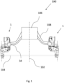
- the container To fill a container to be filled, the container is held on the container holder 4 rigidly attached to the support bolt 2 and the filling valve 30 is lowered onto the container to be filled relative to the support bolt 2 so that the filling can be carried out with the filling valve 30 pressed against it.
- connection device 5 has a clamping plate 52 which is rigidly attached to the valve carrier 104.
- the carrier bolt 2 is, as described below with reference to Figure 3 will be described in detail, is guided through a bore 54 of the clamping plate 52 and is held in a fixed position by means of two adjusting nuts 50, 50' in the direction of the bolt's longitudinal axis 22, thus in its height relative to the clamping plate 52 and thus in its height relative to the valve carrier 104.
- the support bolt 2 is supported by the first adjusting nut 50 on the clamping plate 52 from above, thus in the direction of the acceleration due to gravity.
- the second adjusting nut 50 acts as a lock nut, so that the support bolt 2 is clamped to the clamping plate 52 and is thus fixed in a fixed position.
- the height adjustment of the support bolt 2 provided by the connection device 5 is carried out by turning the first adjusting nut 50, whereby the second adjusting nut 50' must be loosened beforehand in order to release the previously described clamped state.
- Turning the first adjusting nut 50 on the adjusting thread 20 causes a displacement of the adjusting nut 50 in the direction of the bolt's longitudinal axis 22. Consequently, the support bolt 2 experiences a displacement relative to the clamping plate 52 in the direction of its bolt's longitudinal axis 22, which corresponds to the displacement of the adjusting nut 50.
Landscapes
- Filling Of Jars Or Cans And Processes For Cleaning And Sealing Jars (AREA)
Claims (6)
- Dispositif (1) pour le remplissage d'un contenant avec un produit de remplissage, de préférence pour le remplissage d'un contenant dans une installation de remplissage de boissons, comprenant un boulon de support (2), un organe de remplissage (3) disposé sur le boulon de support (2) comportant une soupape de remplissage (30) mobile le long d'un axe longitudinal (32) de l'organe de remplissage (3) par rapport au boulon de support (2), et un élément de maintien de contenant (4) fixé rigidement au boulon de support (2) au-dessous de la soupape de remplissage (30) pour le maintien d'un contenant à remplir,
caractérisé par
un dispositif de liaison (5) pour la liaison réglable en hauteur du boulon de support (2) à un dispositif de transport, de préférence à un support de soupape (104), d'un dispositif de remplissage (100), dans lequel le dispositif de liaison (5) présente au moins un écrou de réglage (50, 50') en prise avec un filetage de réglage (20) prévu sur le boulon de support (2). - Dispositif (1) selon la revendication 1, caractérisé en ce que deux écrous de réglage (50, 50') sont prévus, dans lequel un premier écrou de réglage (50) agit depuis un premier côté du dispositif de liaison (5) et un second écrou de réglage (50') agit depuis un côté du dispositif de liaison (5) opposé au premier écrou de réglage (50).
- Dispositif (1) selon la revendication 1 ou 2, caractérisé en ce que le dispositif de liaison (5) présente une plaque de serrage (52) pour la fixation rigide au dispositif de transport, dans lequel de préférence le réglage en hauteur du boulon de support (2) est effectué par rapport à la plaque de serrage (52).
- Dispositif (1) selon l'une des revendications précédentes, caractérisé en ce que le dispositif de liaison (5) présente un élément d'alignement pour l'alignement du dispositif (1) sur le dispositif de transport, vu perpendiculairement à l'axe longitudinal (32), de préférence un élément à rainure et/ou un élément à ressort et/ou une broche.
- Dispositif (1) selon l'une des revendications précédentes, caractérisé en ce que l'organe de remplissage (3) et l'élément de maintien de contenant (4) sont disposés sur le boulon de support (2) de telle sorte que, lorsque la soupape de remplissage (30) est pressée sur un contenant maintenu dans l'élément de maintien de contenant (4), les forces et/ou couples résultant du pressage sont absorbés par le boulon de support (2).
- Dispositif de remplissage (100) pour le versement d'un produit de remplissage dans un contenant, comprenant un support de soupape (104) pouvant tourner autour d'un axe de rotation central (102) et au moins un dispositif (1) pour le remplissage d'un contenant avec un produit de remplissage selon l'une des revendications précédentes.
Applications Claiming Priority (2)
| Application Number | Priority Date | Filing Date | Title |
|---|---|---|---|
| DE102017119347.2A DE102017119347A1 (de) | 2017-08-24 | 2017-08-24 | Vorrichtung zum Befüllen eines Behälters mit einem Füllprodukt und Abfüllvorrichtung |
| PCT/EP2018/072843 WO2019038413A1 (fr) | 2017-08-24 | 2018-08-24 | Dispositif de remplissage d'un contenant |
Publications (3)
| Publication Number | Publication Date |
|---|---|
| EP3672902A1 EP3672902A1 (fr) | 2020-07-01 |
| EP3672902B1 true EP3672902B1 (fr) | 2024-07-10 |
| EP3672902C0 EP3672902C0 (fr) | 2024-07-10 |
Family
ID=63371695
Family Applications (1)
| Application Number | Title | Priority Date | Filing Date |
|---|---|---|---|
| EP18759619.2A Active EP3672902B1 (fr) | 2017-08-24 | 2018-08-24 | Dispositif pour le remplissage d'un récipient |
Country Status (4)
| Country | Link |
|---|---|
| EP (1) | EP3672902B1 (fr) |
| CN (1) | CN111094171B (fr) |
| DE (1) | DE102017119347A1 (fr) |
| WO (1) | WO2019038413A1 (fr) |
Citations (1)
| Publication number | Priority date | Publication date | Assignee | Title |
|---|---|---|---|---|
| DE9412952U1 (de) * | 1994-08-11 | 1995-09-07 | Kronseder, Hermann, Dr.-Ing.E.h., 93086 Wörth | Gefäßbehandlungsmaschine |
Family Cites Families (8)
| Publication number | Priority date | Publication date | Assignee | Title |
|---|---|---|---|---|
| US998266A (en) * | 1910-06-21 | 1911-07-18 | Adolph Schneider | Bottle-filling machine. |
| NL164820C (nl) * | 1971-02-11 | 1981-02-16 | Stork Amsterdam | Inrichting voor het vullen van houders. |
| DE4332325A1 (de) * | 1993-09-23 | 1995-03-30 | Alfill Getraenketechnik | Zentriervorrichtung für Behälterfüllmaschinen |
| DE102012220091A1 (de) * | 2012-11-05 | 2014-05-08 | Krones Ag | Vorrichtung und Verfahren zum Ausstatten von Behältern mit Klebeetiketten |
| DE102013206685A1 (de) * | 2013-04-15 | 2014-10-30 | Krones Ag | Behälterbehandlungsmodul zum Einsatz in Behälterbehandlungsmaschinen |
| CN203683030U (zh) * | 2013-11-11 | 2014-07-02 | 常州纺织服装职业技术学院 | 一种轧盖机 |
| CN204162396U (zh) * | 2014-09-15 | 2015-02-18 | 广州达意隆包装机械股份有限公司 | 托瓶进瓶装置 |
| CN204527667U (zh) * | 2014-12-24 | 2015-08-05 | 海门市金昊自动化科技有限公司 | 智能型辣酱灌装机 |
-
2017
- 2017-08-24 DE DE102017119347.2A patent/DE102017119347A1/de active Pending
-
2018
- 2018-08-24 EP EP18759619.2A patent/EP3672902B1/fr active Active
- 2018-08-24 WO PCT/EP2018/072843 patent/WO2019038413A1/fr not_active Ceased
- 2018-08-24 CN CN201880060100.XA patent/CN111094171B/zh active Active
Patent Citations (1)
| Publication number | Priority date | Publication date | Assignee | Title |
|---|---|---|---|---|
| DE9412952U1 (de) * | 1994-08-11 | 1995-09-07 | Kronseder, Hermann, Dr.-Ing.E.h., 93086 Wörth | Gefäßbehandlungsmaschine |
Also Published As
| Publication number | Publication date |
|---|---|
| EP3672902A1 (fr) | 2020-07-01 |
| WO2019038413A1 (fr) | 2019-02-28 |
| CN111094171B (zh) | 2022-10-18 |
| DE102017119347A1 (de) | 2019-02-28 |
| CN111094171A (zh) | 2020-05-01 |
| EP3672902C0 (fr) | 2024-07-10 |
Similar Documents
| Publication | Publication Date | Title |
|---|---|---|
| EP3077305B1 (fr) | Étoile de transport comportant des réceptacles d'étoile réglables | |
| EP2910331B1 (fr) | Dispositif de serrage de boulons hydraulique | |
| DE102009025907A1 (de) | Vorrichtung und Verfahren zur Behandlung von Behältern | |
| CH619629A5 (fr) | ||
| EP3912939A1 (fr) | Dispositif de serrage et dispositif de manutention de conteneurs | |
| DE102017116092A1 (de) | Spannsystem, Transportglied sowie Drohne | |
| DE2030040A1 (fr) | ||
| AT519U1 (de) | Spritzgiessmaschine | |
| EP3672902B1 (fr) | Dispositif pour le remplissage d'un récipient | |
| EP3912937A1 (fr) | Dispositif de définition d'une position de bras de pince et dispositif de transport de récipients | |
| EP1600226B1 (fr) | Méthode et ensemble palier pour la connection détachable d'un outil de préhension à une barre transversale d'une presse de transfert | |
| EP2620636B1 (fr) | Dispositif d'arrêt pour un embrayage d'une éolienne | |
| DE102004021606A1 (de) | Drehübertrager zum Einführen eines flüssigen oder gasförmigen Mediums in ein rotierendes Bauteil einer Druckmaschine | |
| EP2930118B1 (fr) | Dispositif de manipulation de récipient et procédé de maintien, de préhension et/ou de rotation de récipients | |
| DE19851527A1 (de) | Füllvorrichtung für axiale Pulverpressen | |
| EP3678985B1 (fr) | Dispositif de positionnement pour le positionnement relatif d'un récipient à traiter et d'un dispositif de traitement dans une installation de traitement de récipients | |
| EP3645431B1 (fr) | Dispositif de serrage destiné à retenir un récipient dans une installation de traitement de récipient | |
| EP1761434B1 (fr) | Dispositif et procede pour monter des pompes de pulverisation et des elements similaires sur des recipients et pour les verrouiller | |
| EP1461255A1 (fr) | Dispositif pour maintenir un contenant et procede pour fixer un contenant | |
| DE3406922C2 (fr) | ||
| DE102012005300A1 (de) | Vorrichtung zum zumindest teilweisen Aufschrauben eines Drehverschlusses auf eine Flasche | |
| EP2269813A2 (fr) | Poinçon de presse pour une presse rotative | |
| EP3492218B1 (fr) | Dispositif porte-pièces | |
| DE3031150A1 (de) | Plattenklemmeinrichtung | |
| DE3638544C2 (fr) |
Legal Events
| Date | Code | Title | Description |
|---|---|---|---|
| STAA | Information on the status of an ep patent application or granted ep patent |
Free format text: STATUS: UNKNOWN |
|
| STAA | Information on the status of an ep patent application or granted ep patent |
Free format text: STATUS: THE INTERNATIONAL PUBLICATION HAS BEEN MADE |
|
| PUAI | Public reference made under article 153(3) epc to a published international application that has entered the european phase |
Free format text: ORIGINAL CODE: 0009012 |
|
| STAA | Information on the status of an ep patent application or granted ep patent |
Free format text: STATUS: REQUEST FOR EXAMINATION WAS MADE |
|
| 17P | Request for examination filed |
Effective date: 20200317 |
|
| AK | Designated contracting states |
Kind code of ref document: A1 Designated state(s): AL AT BE BG CH CY CZ DE DK EE ES FI FR GB GR HR HU IE IS IT LI LT LU LV MC MK MT NL NO PL PT RO RS SE SI SK SM TR |
|
| AX | Request for extension of the european patent |
Extension state: BA ME |
|
| DAV | Request for validation of the european patent (deleted) | ||
| DAX | Request for extension of the european patent (deleted) | ||
| STAA | Information on the status of an ep patent application or granted ep patent |
Free format text: STATUS: EXAMINATION IS IN PROGRESS |
|
| 17Q | First examination report despatched |
Effective date: 20220301 |
|
| P01 | Opt-out of the competence of the unified patent court (upc) registered |
Effective date: 20230523 |
|
| GRAP | Despatch of communication of intention to grant a patent |
Free format text: ORIGINAL CODE: EPIDOSNIGR1 |
|
| STAA | Information on the status of an ep patent application or granted ep patent |
Free format text: STATUS: GRANT OF PATENT IS INTENDED |
|
| INTG | Intention to grant announced |
Effective date: 20240131 |
|
| GRAS | Grant fee paid |
Free format text: ORIGINAL CODE: EPIDOSNIGR3 |
|
| GRAA | (expected) grant |
Free format text: ORIGINAL CODE: 0009210 |
|
| STAA | Information on the status of an ep patent application or granted ep patent |
Free format text: STATUS: THE PATENT HAS BEEN GRANTED |
|
| AK | Designated contracting states |
Kind code of ref document: B1 Designated state(s): AL AT BE BG CH CY CZ DE DK EE ES FI FR GB GR HR HU IE IS IT LI LT LU LV MC MK MT NL NO PL PT RO RS SE SI SK SM TR |
|
| REG | Reference to a national code |
Ref country code: CH Ref legal event code: EP |
|
| REG | Reference to a national code |
Ref country code: DE Ref legal event code: R096 Ref document number: 502018014844 Country of ref document: DE |
|
| U01 | Request for unitary effect filed |
Effective date: 20240710 |
|
| U07 | Unitary effect registered |
Designated state(s): AT BE BG DE DK EE FI FR IT LT LU LV MT NL PT SE SI Effective date: 20240723 |
|
| P04 | Withdrawal of opt-out of the competence of the unified patent court (upc) registered |
Free format text: CASE NUMBER: APP_42575/2024 Effective date: 20240719 |
|
| U20 | Renewal fee for the european patent with unitary effect paid |
Year of fee payment: 7 Effective date: 20240723 |
|
| P05 | Withdrawal of opt-out of the competence of the unified patent court (upc) changed |
Free format text: CASE NUMBER: APP_42575/2024 Effective date: 20240723 |
|
| PG25 | Lapsed in a contracting state [announced via postgrant information from national office to epo] |
Ref country code: NO Free format text: LAPSE BECAUSE OF FAILURE TO SUBMIT A TRANSLATION OF THE DESCRIPTION OR TO PAY THE FEE WITHIN THE PRESCRIBED TIME-LIMIT Effective date: 20241010 |
|
| PG25 | Lapsed in a contracting state [announced via postgrant information from national office to epo] |
Ref country code: GR Free format text: LAPSE BECAUSE OF FAILURE TO SUBMIT A TRANSLATION OF THE DESCRIPTION OR TO PAY THE FEE WITHIN THE PRESCRIBED TIME-LIMIT Effective date: 20241011 Ref country code: PL Free format text: LAPSE BECAUSE OF FAILURE TO SUBMIT A TRANSLATION OF THE DESCRIPTION OR TO PAY THE FEE WITHIN THE PRESCRIBED TIME-LIMIT Effective date: 20240710 |
|
| PG25 | Lapsed in a contracting state [announced via postgrant information from national office to epo] |
Ref country code: IS Free format text: LAPSE BECAUSE OF FAILURE TO SUBMIT A TRANSLATION OF THE DESCRIPTION OR TO PAY THE FEE WITHIN THE PRESCRIBED TIME-LIMIT Effective date: 20241110 |
|
| PG25 | Lapsed in a contracting state [announced via postgrant information from national office to epo] |
Ref country code: HR Free format text: LAPSE BECAUSE OF FAILURE TO SUBMIT A TRANSLATION OF THE DESCRIPTION OR TO PAY THE FEE WITHIN THE PRESCRIBED TIME-LIMIT Effective date: 20240710 |
|
| PG25 | Lapsed in a contracting state [announced via postgrant information from national office to epo] |
Ref country code: ES Free format text: LAPSE BECAUSE OF FAILURE TO SUBMIT A TRANSLATION OF THE DESCRIPTION OR TO PAY THE FEE WITHIN THE PRESCRIBED TIME-LIMIT Effective date: 20240710 Ref country code: RS Free format text: LAPSE BECAUSE OF FAILURE TO SUBMIT A TRANSLATION OF THE DESCRIPTION OR TO PAY THE FEE WITHIN THE PRESCRIBED TIME-LIMIT Effective date: 20241010 |
|
| PG25 | Lapsed in a contracting state [announced via postgrant information from national office to epo] |
Ref country code: RS Free format text: LAPSE BECAUSE OF FAILURE TO SUBMIT A TRANSLATION OF THE DESCRIPTION OR TO PAY THE FEE WITHIN THE PRESCRIBED TIME-LIMIT Effective date: 20241010 Ref country code: PL Free format text: LAPSE BECAUSE OF FAILURE TO SUBMIT A TRANSLATION OF THE DESCRIPTION OR TO PAY THE FEE WITHIN THE PRESCRIBED TIME-LIMIT Effective date: 20240710 Ref country code: NO Free format text: LAPSE BECAUSE OF FAILURE TO SUBMIT A TRANSLATION OF THE DESCRIPTION OR TO PAY THE FEE WITHIN THE PRESCRIBED TIME-LIMIT Effective date: 20241010 Ref country code: IS Free format text: LAPSE BECAUSE OF FAILURE TO SUBMIT A TRANSLATION OF THE DESCRIPTION OR TO PAY THE FEE WITHIN THE PRESCRIBED TIME-LIMIT Effective date: 20241110 Ref country code: HR Free format text: LAPSE BECAUSE OF FAILURE TO SUBMIT A TRANSLATION OF THE DESCRIPTION OR TO PAY THE FEE WITHIN THE PRESCRIBED TIME-LIMIT Effective date: 20240710 Ref country code: GR Free format text: LAPSE BECAUSE OF FAILURE TO SUBMIT A TRANSLATION OF THE DESCRIPTION OR TO PAY THE FEE WITHIN THE PRESCRIBED TIME-LIMIT Effective date: 20241011 Ref country code: ES Free format text: LAPSE BECAUSE OF FAILURE TO SUBMIT A TRANSLATION OF THE DESCRIPTION OR TO PAY THE FEE WITHIN THE PRESCRIBED TIME-LIMIT Effective date: 20240710 |
|
| U1N | Appointed representative for the unitary patent procedure changed after the registration of the unitary effect |
Representative=s name: NORDMEYER, PHILIPP WERNER; DE |
|
| REG | Reference to a national code |
Ref country code: CH Ref legal event code: PL |
|
| PG25 | Lapsed in a contracting state [announced via postgrant information from national office to epo] |
Ref country code: SM Free format text: LAPSE BECAUSE OF FAILURE TO SUBMIT A TRANSLATION OF THE DESCRIPTION OR TO PAY THE FEE WITHIN THE PRESCRIBED TIME-LIMIT Effective date: 20240710 |
|
| PG25 | Lapsed in a contracting state [announced via postgrant information from national office to epo] |
Ref country code: CH Free format text: LAPSE BECAUSE OF NON-PAYMENT OF DUE FEES Effective date: 20240831 Ref country code: MC Free format text: LAPSE BECAUSE OF FAILURE TO SUBMIT A TRANSLATION OF THE DESCRIPTION OR TO PAY THE FEE WITHIN THE PRESCRIBED TIME-LIMIT Effective date: 20240710 |
|
| PG25 | Lapsed in a contracting state [announced via postgrant information from national office to epo] |
Ref country code: CZ Free format text: LAPSE BECAUSE OF FAILURE TO SUBMIT A TRANSLATION OF THE DESCRIPTION OR TO PAY THE FEE WITHIN THE PRESCRIBED TIME-LIMIT Effective date: 20240710 |
|
| PG25 | Lapsed in a contracting state [announced via postgrant information from national office to epo] |
Ref country code: SK Free format text: LAPSE BECAUSE OF FAILURE TO SUBMIT A TRANSLATION OF THE DESCRIPTION OR TO PAY THE FEE WITHIN THE PRESCRIBED TIME-LIMIT Effective date: 20240710 |
|
| PLBE | No opposition filed within time limit |
Free format text: ORIGINAL CODE: 0009261 |
|
| STAA | Information on the status of an ep patent application or granted ep patent |
Free format text: STATUS: NO OPPOSITION FILED WITHIN TIME LIMIT |
|
| 26N | No opposition filed |
Effective date: 20250411 |
|
| GBPC | Gb: european patent ceased through non-payment of renewal fee |
Effective date: 20241010 |
|
| PG25 | Lapsed in a contracting state [announced via postgrant information from national office to epo] |
Ref country code: GB Free format text: LAPSE BECAUSE OF NON-PAYMENT OF DUE FEES Effective date: 20241010 |
|
| PG25 | Lapsed in a contracting state [announced via postgrant information from national office to epo] |
Ref country code: IE Free format text: LAPSE BECAUSE OF NON-PAYMENT OF DUE FEES Effective date: 20240824 |
|
| U20 | Renewal fee for the european patent with unitary effect paid |
Year of fee payment: 8 Effective date: 20250709 |
|
| PG25 | Lapsed in a contracting state [announced via postgrant information from national office to epo] |
Ref country code: RO Free format text: LAPSE BECAUSE OF FAILURE TO SUBMIT A TRANSLATION OF THE DESCRIPTION OR TO PAY THE FEE WITHIN THE PRESCRIBED TIME-LIMIT Effective date: 20240710 |
|
| PG25 | Lapsed in a contracting state [announced via postgrant information from national office to epo] |
Ref country code: CY Free format text: LAPSE BECAUSE OF FAILURE TO SUBMIT A TRANSLATION OF THE DESCRIPTION OR TO PAY THE FEE WITHIN THE PRESCRIBED TIME-LIMIT; INVALID AB INITIO Effective date: 20180824 |
|
| PG25 | Lapsed in a contracting state [announced via postgrant information from national office to epo] |
Ref country code: HU Free format text: LAPSE BECAUSE OF FAILURE TO SUBMIT A TRANSLATION OF THE DESCRIPTION OR TO PAY THE FEE WITHIN THE PRESCRIBED TIME-LIMIT; INVALID AB INITIO Effective date: 20180824 |