EP3672866B1 - Antriebsvorrichtung für wasserfahrzeuge - Google Patents
Antriebsvorrichtung für wasserfahrzeuge Download PDFInfo
- Publication number
- EP3672866B1 EP3672866B1 EP18848946.2A EP18848946A EP3672866B1 EP 3672866 B1 EP3672866 B1 EP 3672866B1 EP 18848946 A EP18848946 A EP 18848946A EP 3672866 B1 EP3672866 B1 EP 3672866B1
- Authority
- EP
- European Patent Office
- Prior art keywords
- watercraft
- pair
- propulsion mechanism
- cables
- flexible fins
- Prior art date
- Legal status (The legal status is an assumption and is not a legal conclusion. Google has not performed a legal analysis and makes no representation as to the accuracy of the status listed.)
- Active
Links
Images













Classifications
-
- B—PERFORMING OPERATIONS; TRANSPORTING
- B63—SHIPS OR OTHER WATERBORNE VESSELS; RELATED EQUIPMENT
- B63H—MARINE PROPULSION OR STEERING
- B63H16/00—Marine propulsion by muscle power
- B63H16/04—Oars; Sculls; Paddles; Poles
-
- B—PERFORMING OPERATIONS; TRANSPORTING
- B63—SHIPS OR OTHER WATERBORNE VESSELS; RELATED EQUIPMENT
- B63B—SHIPS OR OTHER WATERBORNE VESSELS; EQUIPMENT FOR SHIPPING
- B63B34/00—Vessels specially adapted for water sports or leisure; Body-supporting devices specially adapted for water sports or leisure
- B63B34/26—Accessories for canoes, kayaks or the like
-
- B—PERFORMING OPERATIONS; TRANSPORTING
- B63—SHIPS OR OTHER WATERBORNE VESSELS; RELATED EQUIPMENT
- B63H—MARINE PROPULSION OR STEERING
- B63H1/00—Propulsive elements directly acting on water
- B63H1/30—Propulsive elements directly acting on water of non-rotary type
- B63H1/36—Propulsive elements directly acting on water of non-rotary type swinging sideways, e.g. fishtail type
-
- B—PERFORMING OPERATIONS; TRANSPORTING
- B63—SHIPS OR OTHER WATERBORNE VESSELS; RELATED EQUIPMENT
- B63H—MARINE PROPULSION OR STEERING
- B63H16/00—Marine propulsion by muscle power
- B63H16/08—Other apparatus for converting muscle power into propulsive effort
- B63H16/18—Other apparatus for converting muscle power into propulsive effort using sliding or pivoting handle or pedal, i.e. the motive force being transmitted to a propelling means by means of a lever operated by the hand or foot of the occupant
-
- B—PERFORMING OPERATIONS; TRANSPORTING
- B63—SHIPS OR OTHER WATERBORNE VESSELS; RELATED EQUIPMENT
- B63H—MARINE PROPULSION OR STEERING
- B63H16/00—Marine propulsion by muscle power
- B63H16/08—Other apparatus for converting muscle power into propulsive effort
- B63H16/20—Other apparatus for converting muscle power into propulsive effort using rotary cranking arm
Definitions
- This invention relates to novel propulsion means for a watercraft using oscillating foils with ability to provide thrust in any direction.
- Oscillating fin propulsion has been used to produce efficient propulsion.
- This technology appears in US2014/134901 or U.S. Pat. No. 6,022,249 , which discloses a self-propelled watercraft, such as a kayak, which typically include a hull with a keel, having propulsion means extending below the water line.
- the propulsion means comprises a pair of fins each having a leading edge and a trailing edge and adapted to oscillate through an arcuate path in a generally transverse direction with respect to the central longitudinal dimension of the watercraft.
- Foot operated pedals worked from the cockpit are operatively associated with the propulsion means for applying input force to the propulsion means.
- the propulsion means includes a pair of fins which twist to form an angle of attack for providing forward thrust with respect to the longitudinal dimension of the watercraft while moving in both directions along the arcuate path.
- U.S. Pat. No. 9,359,052 also discloses a self-propelled watercraft having propulsion means extending below the water line comprising a pair of flexible fins each rotatable on a substantially horizontal axis and each being adapted to oscillate through an arcuate path in a generally transverse direction with respect to the central longitudinal dimension of the watercraft.
- Input means are operatively associated with the pair of flexible fins for applying input force to oscillate the pair of flexible fins.
- An improvement is provided by means for positioning the pair of flexible fins to propel the watercraft forward and to rotate the pair of flexible fins 180° about separate axes which are each disposed at a substantially right angle to the horizontal axis to propel the watercraft aft.
- the flexible fins When input force is applied, the flexible fins can twist to form an angle of attack for providing forward or aft thrust with respect to the longitudinal dimension of the watercraft while moving the flexible fins in both directions along the arcuate path. However, it is not possible to provide thrust other than in forward or aft directions.
- a propulsion mechanism adapted to be inserted in an opening in the bottom of a watercraft comprising a pair of flexible fins extending below the water line, said pair of flexible fins each adapted to oscillate through an arcuate path on a horizontal axis to propel the watercraft, said horizontal axis being continuously rotatable in either direction about a generally vertical axis to propel said watercraft in any direction, and means operatively associated with said propulsion fins for applying input force whereby as input force is applied, said flexible fins can twist to form an angle of attack for providing thrust while moving in both directions along said arcuate path.
- a novel watercraft comprising a propulsion mechanism extending through an opening in the bottom of the watercraft, said propulsion mechanism comprising a pair of flexible fins extending below the water line, said pair of flexible fins each adapted to oscillate through an arcuate path on a horizontal axis to propel the watercraft, said horizontal axis being continuously rotatable in either direction about a generally vertical axis to propel said watercraft in any direction, and means operatively associated with said propulsion fins for applying input force whereby as input force is applied, said flexible fins can twist to form an angle of attack for providing thrust while moving in both directions along said arcuate path.
- a propulsion mechanism adapted to be inserted in an opening in the bottom of a watercraft comprising a pair of flexible fins extending below the water line, said pair of flexible fins each adapted to oscillate through an arcuate path on a horizontal axis to propel the watercraft, said horizontal axis being continuously rotatable in either direction about a generally vertical axis to propel said watercraft in any direction, and a pair of pedals operatively associated with said propulsion fins for applying input force whereby as input force is applied, said flexible fins can twist to form an angle of attack for providing thrust while moving in both directions along said arcuate path.
- a novel watercraft comprising a propulsion mechanism extending through an opening in the bottom of the watercraft, said propulsion mechanism comprising a pair of flexible fins extending below the water line, said pair of flexible fins each adapted to oscillate through an arcuate path on a horizontal axis to propel the watercraft, said horizontal axis being continuously rotatable in either direction about a generally vertical axis to propel said watercraft in any direction, and a pair of pedals operatively associated with said propulsion fins for applying input force whereby as input force is applied, said flexible fins can twist to form an angle of attack for providing thrust while moving in both directions along said arcuate path.
- a propulsion mechanism adapted to be inserted in an opening in the bottom of a watercraft comprising a pair of flexible fins extending below the water line, said pair of flexible fins each adapted to oscillate through an arcuate path on a horizontal axis to propel the watercraft, said horizontal axis being continuously rotatable in either direction about a generally vertical axis to propel said watercraft in any direction, the vertical axis being coupled to elements operable from within the watercraft to steer the watercraft in any direction while being pedaled, and a pair of pedals operatively associated with the propulsion fins for applying input force whereby as input force is applied, the flexible fins can twist to form an angle of attack for providing thrust while moving in both directions along the arcuate path.
- a novel watercraft comprising a propulsion mechanism extending through an opening in the bottom of the watercraft, said propulsion mechanism comprising a pair of flexible fins extending below the water line, said pair of flexible fins each adapted to oscillate through an arcuate path on a horizontal axis to propel the watercraft, said horizontal axis being continuously rotatable in either direction about a generally vertical axis to propel said watercraft in any direction, said vertical axis being coupled to elements operable from within the watercraft to steer the watercraft in any direction while being pedaled, and a pair of pedals operatively associated with the propulsion fins for applying input force whereby as input force is applied, the flexible fins can twist to form an angle of attack for providing thrust while moving in both directions along the arcuate path.
- this invention comprises a novel watercraft comprising a propulsion mechanism extending through an opening in the bottom of the watercraft.
- the propulsion mechanism is adapted to rotate about a generally vertical axis coupled to elements operable from within the watercraft to rotate the propulsion mechanism in any direction.
- the watercraft has locking means to prevent the propulsion mechanism from rotating.
- the locking means are adapted to disengage when the elements are operated.
- a pair of pedals are operatively associated with the propulsion mechanism for applying input force whereby as input force is applied thrust is produced.
- a key feature of this invention's design is that the drive can produce thrust in any direction which adds to the maneuverability of the boat.
- the fins are able to rotate as a pair around a single vertical axis. This means the lower section or “lower unit” of the drive comprising the fins is able to be rotated independently of the upper section or “upper unit” comprising the means for applying input force, preferably pedals, allowing the drive to thrust in any direction.
- This invention dramatically increases the maneuverability of kayaks, allowing the drive to be used to propel and turn the boat.
- both the drive and the rudder can be used independently to maneuver the boat, further increasing the maneuverability.
- the lower unit can also be rotated 180 degrees into a reverse position, and then the user can thrust in reverse with the drive and steer with the rudder.
- the drive can, however, be used as the sole means of propulsion and steering on a watercraft.
- the ability to rotate the drive to any direction through 360° is even more beneficial than reverse. It allows the watercraft to rotate about its own axis and move sideways through the water, hold in a location pointing any direction, and provides extremely precise and effective maneuverability.
- Another feature of this invention is that an indicator can be placed on top of the device which shows the direction that the watercraft will be thrusted.
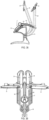
- This invention uses a four cable transmission system with modifications to allow the rotation of the lower unit. All four cables are redirected to be grouped around and parallel to the vertical axis of the pivot that has been added to the drive. Each set of cables that transmit the force at the same time are located on opposite sides of the vertical axis. Each of the four cables are separated into two lengths of cable, with the break occurring halfway along the vertical length of cable.
- One set of upper cables is attached to a free-floating horizontal bearing ring. This ring interfaces with another free-floating horizontal bearing ring, with ball bearings between the two rings. This second ring is attached to the lower sections of cable. The second set of upper cables is attached to a smaller horizontal free-floating bearing ring.
- This ring interfaces with another small free-floating horizontal bearing ring, with ball bearings between flanges on the two rings.
- This second ring is attached to the lower sections of cable.
- This smaller horizontal bearing ring assembly is small enough to pass freely inside the larger bearing ring assembly.
- the larger ring bearing moves up and down along the vertical axis.
- the smaller ring bearing assembly also travels up and down along the vertical axis, in an opposite direction to the larger bearing ring assembly. With each pedal stroke, the smaller ring assembly passes through the larger ring assembly.
- the two ring bearing assemblies allow for the lower unit to rotate independently of the upper unit. As the lower unit is pivoted around the vertical axis, the lower bearing rings rotate with the lower cables and lower unit and the upper bearing rings and upper cables do not rotate.
- the ball bearings between each upper and lower bearing ring allow for free rotation even under high cable tension.
- the bearing ring assemblies are free to rotate a full 360° at any position along the vertical axis, and can be rotated when the drive is being pedaled or not being pedaled.
- Another feature of this invention is the drive steering systems and clutch which allows for the user to control the position of the lower unit of the drive, and therefore the direction of thrust, by operating a steering handle located within arm's reach of the user.
- This handle rotates around a vertical axis, and the direction the handle is pointing correlates with the direction of thrust from the drive.
- This handle can be rotated infinitely in either direction.
- the clutch serves to keep the lower unit fixed while the drive is in use, but to allow the user to turn the lower unit with the handle. Force from the lower unit will not release the clutch. If the lower unit is over forced, as upon hitting a submerged object, there is a built in slip mechanism to allow all parts of the steering system to rotate, including the clutch. This is to avoid high load damaging the clutch or the steering system.
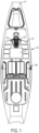
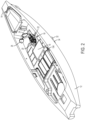
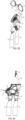
- Figure 1 shows a preferred watercraft 10 having a hull 12, a bow 14, a cockpit 16 having a floor 18, a through well or opening 20 in which is received the propulsion mechanism 22 of this invention.
- the pedals 24 and 26, pedal shafts 28 and 30 and fins 32 and 34 all form part of propulsion mechanism 22.
- the pedals 18 and 20 are operatively connected to pedal shafts 26 and 28.
- the supporting structure for the propulsion mechanism is spine 21.
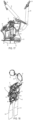
- the drums 40 and 42 are rotated about a horizontal axis represented by shaft 45 in Figure 4 .
- the fins 32 and 34 oscillate on a horizontal axis through an arcuate path to propel the watercraft.
- each bearing ring assembly has an upper and lower ring separated by a ring of ball bearings.
- the two bearing ring assemblies are nested, one inside the other.
- the large bearing ring assembly 38 has an upper non-rotatable ring 44 and a lower rotatable ring 46.
- the lower ring 46 rotates with respect to the upper non-rotatable ring 44 on ball bearing ring 48.
- the smaller inner bearing ring assembly 36 also has an upper non-rotatable small ring 50 and a lower rotatable small ring 52.
- the lower ring 52 rotates on ball bearing ring 53.
- Each rotatable ring 46, 52 carries two downwardly extending cables.
- Rotatable ring 46 carries cables 54 and 56.
- Rotatable ring 52 carries cables 58 and 60.
- cable 54 runs to the front of drum 40.
- Cable 56 runs to the rear of drum 42.
- cable 58 runs to the front of drum 42 and cable 60 runs to the rear of drum 40.
- Non-rotatable small ring 50 carries two upwardly extending cables 68 and 70.
- Non-rotatable ring 44 also carries two upwardly extending cable 72 and 74.
- pedal shafts 28 and 30 rotate about a fixed shaft 76.
- Shaft 76 carries cable guide elements 78 and 80 which rotate with pedal shaft 28 about shaft 76.
- Guide elements 82 and 84 rotate with pedal shaft 30 about shaft 76 as shown in Figure 28 .
- a pair of pulleys 86 and 88 are carried at the top of central vertical shaft 90. Each pulley supports two of the cables 68 and 72 passing over pulley 86 and cables 70 and 74 passing over pulley 88.
- the horizontal shaft 45 carries the drums 40 and 42 to which is joined masts 92 and 94, carrying fins 32 and 34.
- the horizontal shaft 45 is connected to central vertical shaft 90.
- the vertical shaft 90 projects upwardly and generally, although not necessarily, forms a substantially right angle to the longitudinal dimension of the watercraft.
- the horizontal shaft 45 is continuously rotatable through 360° in either direction about vertical shaft 90.
- steering is performed by the occupant of the cockpit by operating handle 104 with steering rod 105 which is coupled to compression tube 106 containing toothed belt 120 through connection 108 to turn pinion gear 110.
- Pinion gear 110 engages ring or spur gear 112 which is carried by vertical shaft 90.
- each of the fins is rotatable about its mast, so that the edge of the fin opposite the leading edge can move from one side to the other with respect to the center line of drums 40 and 42.
- This action results in both fins exerting of forward force or push on the watercraft in both directions of movement of the fins, providing superior efficiency and speed.
- the extent of travel or movement of the trailing edges is limited by the adjustment provided by tensioners 62 and 64.
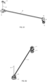
- the rear pulley 96 carries cable 98 which runs from attachment 100 connected to pedal shaft 28 to attachment 102 connected to pedal shaft 30.
- the other is pulled back.
- one bearing assembly is pulled up, the other bearing assembly is pulled down as the pedal is advanced, and the other pedal is pulled back, thereby being made ready to be advanced by input force to the other pedal to pull up the other bearing assembly.
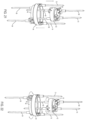
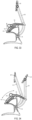
- FIGs 32 to 35 illustrate a preferred feature of the invention.
- Each of the pedal shafts 28 and 30 carries a pivotally attached arm 114 having at its free end a series of teeth 116 which engage curved rack 118.
- the teeth 116 can be made to engage at any point up or down the rack 118 as shown in Figure 34 , followed by re-engaging the teeth 116 at the selected location, Figure 35 .
- the occupant of the cockpit can adjust the distance from the cockpit to the pedals 24, 26 to suit.
- the direction indicator 97 is attached via a flexible rod 99 to the vertical shaft 90.
- This vertical shaft 90 is attached to the horizontal shaft 45 so the indicator rotates when the horizontal shaft 45, along with drums 40, 42 and fins 32, 34, rotates.
- the drive steering system allows for the user to control the position of the lower unit of the drive, and therefore the direction of thrust, by operating a steering handle 104 located within arm's reach of the user.
- This handle 104 rotates around a vertical axis, and the direction the handle 104 is pointing correlates with the direction of thrust from the drive.
- This handle 104 can be rotated infinitely in either direction.
- the steering system comprises a handle 104 affixed to a vertical shaft 105 that enters the hull of the boat.
- the shaft 105 is then connected to the ring gear 124 of a planetary gear system within housing cover 122 and housing element 123.
- This planetary gear system both reverses the direction of rotation, and doubles the angular rotation.
- the sun gear 126 output of this planetary gear system 127 is mated to a toothed drum 128 that interfaces with the toothed belt 120.
- This belt 120 runs through the compression tube 106 to a clutch system that mates with the drive.
- Both the steering system and the clutch system are provided with a pair of idler pulleys 109, 111 to tension belt 120.
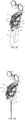
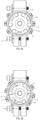
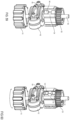
- the toothed belt 120 interfaces with a toothed drum 130 on the clutch system, Figure 53 .
- This drum has tines 132 attached to the bottom of it that extend down into a clutch mechanism. When the user turns the handle 104, these tines press on roller bearings 134, forcing them away from the clutch surface, releasing the clutch and allowing the steering system to rotate.
- the purpose of the clutch is to keep the propulsion mechanism fixed while the drive is in use, but to allow the user to turn the lower unit with the handle 104. Force from the lower unit will not release the clutch. If the lower unit is over forced (in the case of hitting a submerged object for example) there is a built in slip mechanism to allow all parts of the steering system to rotate, including the clutch.
- the output shaft from the clutch is mated to a gear 110 that interlocks with a gear 112 on the drive.
- a gear 110 that interlocks with a gear 112 on the drive.
- the gear 112 on the drive is twice as big as the clutch gear 110, and these mated gears turn opposite directions. This is why the planetary gear ratio and reversal in the steering system is necessary.
- the Dual Clutch Mechanism In the propulsion mechanism of this invention rotatable through 360°, there is preferably a dual clutch system which is a subsystem of the steering system located in the well 20, directly next to the drive, interfacing with the lower unit of the drive by way of a 1:2 ratio spur gear.
- the spur gear 112 on the drive mates slidably with the spur gear 110 on the lower end of the dual clutch mechanism.
- This spur gear 110 is affixed to the output shaft 136 of the clutch.
- the purpose of the clutch is to allow rotational force from the steering handle 104 to rotate the lower unit of the drive, while resisting any rotational torque from the lower unit of the drive on the clutch output shaft 136. This allows the drive to be locked in position whenever the user is not actively turning the drive with the steering handle 104.
- Toothed Drum (input) - This is the drum 130 that interfaces with the belt drive. It is the input of the dual clutch mechanism. It is a toothed drum 130 with three tines 132 that extend down from the lower surface of the drum 130 and into the clutch mechanism. When the toothed drum 130 is rotated, the tines 132 protruding into the clutch mechanism contact the roller bearings 134, pulling them away from the clutch sleeve 138, allowing free rotation of the clutch output shaft 136.
- Roller Bearings 134 - There are six roller bearings 136, located inside the clutch mechanism.
- Clutch sleeve 138 is the cylindrical component that surrounds the roller bearings.
- the inside wall of the clutch sleeve 138 acts as a fixed clutch surface and interfaces with the roller bearings 136.
- Trilobe - This is the lobed component 140 in the center of the clutch mechanism. It is affixed to the output shaft 136 of the clutch. Its function is to translate rotational force from the spur gear 110 into a camming action of the roller bearings 134 between the clutch sleeve 138 and the trilobe 140. This action locks the output shaft 136 of the clutch mechanism, holding the drive in position.
- Spur Gear - This spur gear 110 interfaces with the spur gear 112 on the drive, and is affixed to the output shaft 136 of the clutch mechanism.
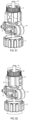
- Figures 56 and 60 indicate, by arrows, the rotational force on the spur gear 110 showing the spur gear as it rotates, rotating the trilobe 140, the cam features on the trilobe pressing three of the roller bearings 134 into the inner wall of the clutch sleeve 138, locking the mechanism. If the spur gear were to be forced in the other direction, the other three roller bearings would lock between the trilobe 140 and the clutch sleeve 138.
- Clutch Overide Bracket - The above described elements of the clutch mechanism are held in bracket 142 which is secured by bolts 144.
- the bracket 142 attaches the clutch sleeve 138 to the well 20. It clamps around a smaller cylindrical section 139 of the clutch sleeve 138. This clamping force can be adjusted to create a specific amount of holding force. If the drive is over powered, to avoid any mechanical failure in the clutch mechanism, the clutch sleeve 138 will slip in the clutch override bracket 142, allowing the drive and steering handle 104 to turn.
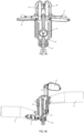
- FIG. 63 to 65 there another embodiment of the invention is shown.
- the two bearing ring assemblies are not present and, hence, the vertical axis 90 about which the drums with fins are continuously rotatable is limited to about 90° to the left and right. While less preferred, this embodiment does afford the user a wide choice in change of direction using the above-described steering mechanism.
- the manually operated steering system shown in detail in Figure 54 can be replaced by an electronic system to operate the drive belt 120 of Figures 51 and 52 .
- the manually operated steering system can be coupled with an electrically powered assist to decrease the input load required of the user to steer.
- FIG 66 this view shows that the propulsion mechanism is supported at its forward extremity at an area 146 in well 20 and at its rear at area 148.
Landscapes
- Chemical & Material Sciences (AREA)
- Engineering & Computer Science (AREA)
- Combustion & Propulsion (AREA)
- Mechanical Engineering (AREA)
- Ocean & Marine Engineering (AREA)
- Mechanical Control Devices (AREA)
Claims (15)
- Antriebsmechanismus (22), der dazu angepasst ist, in eine Öffnung (20) im Boden eines Wasserfahrzeugs (10) eingesetzt zu werden, wobei der Antriebsmechanismus (22) Folgendes umfasst:eine horizontale Welle (45);eine im Allgemeinen vertikale Welle (90);ein Paar flexibler Flossen (32, 34), die sich unterhalb der Wasserlinie erstrecken; undEinrichtungen (24, 26), die betriebsfähig den Flossen (32, 34) zum Aufbringen einer Eingangskraft zugeordnet sind,wobei das Paar flexibler Flossen (32, 34) jeweils dazu angepasst ist, durch einen bogenförmigen Weg auf der horizontalen Welle (45) zu schwingen, um das Wasserfahrzeug (10) anzutreiben, wobei die horizontale Welle (45) kontinuierlich in jeder Richtung um die im Allgemeinen vertikale Welle (90) drehbar ist, um das Wasserfahrzeug (10) in beliebiger Richtung in einer im Allgemeinen horizontalen Ebene anzutreiben, wobei, wenn eine Eingangskraft auf das Paar flexibler Flossen (32, 34) ausgeübt wird, sich das Paar flexibler Flossen (32, 34) verdreht, um einen Anstellwinkel zum Erzeugen von Schub zu bilden, während es sich in beiden Richtungen entlang des bogenförmigen Weges bewegt.
- Antriebsmechanismus (22) nach Anspruch 1, ferner umfassend Pedale (24, 26), wobei obere Seile (68, 70, 72, 74) jedes der Pedale (24, 26) mit Lagerringanordnungen (36, 38) koppeln, wobei jede der Lagerringanordnungen (36, 38) einen oberen nicht drehbaren Ring (44, 50) und einen unteren drehbaren Ring (46, 52) umfasst, wobei die oberen Seile (68, 70, 72, 74) mit den oberen Ringen (44, 50) gekoppelt sind und untere Seile (54, 60) die unteren Ringe (46, 52) mit der horizontalen Welle (45) koppeln, um das Paar flexibler Flossen (32, 34) in Schwingung zu versetzen, wobei sich die unteren Seile (54, 60) und die Lagerringanordnungen (36, 38) in Ausrichtung mit der vertikalen Welle (90) durch eine Eingangskraft auf die Pedale (24, 26) hin- und herbewegen, wobei eine Lagerringanordnung (36) der Lageranordnungen (36, 38) frei durch die andere Lagerringanordnung (38) der Lageranordnungen (36, 38) verläuft.
- Antriebsmechanismus (22) nach Anspruch 2, wobei jedes der Pedale (24, 26) zwei Seile (68, 72) betätigt, wobei ein Seil (68) der zwei Seile (68, 72) mit einem oberen nicht drehbaren Ring (50) der oberen Ringe (44, 50) gekoppelt ist und das andere Seil (72) der zwei Seile (68, 72) mit dem anderen oberen nicht drehbaren Ring (44) der oberen Ringe (44, 50) gekoppelt ist, zwei untere Seile (54, 60) einen unteren drehbaren Ring (46) der unteren Ringe (46, 52) mit der horizontalen Welle (45) gekoppelt sind, und zwei untere Seile (56, 58) den anderen unteren drehbaren Ring (52) der unteren Ringe (46, 52) mit der horizontalen Welle (45) koppeln.
- Antriebsmechanismus (22) nach Anspruch 3, wobei die horizontale Welle (45) eine horizontale Welle (45) umfasst, die zwei auf der Welle schwingbare Trommeln (40, 42) trägt, wobei jede der zwei Trommeln (40, 42) eine des Paars flexibler Flossen (32, 34) trägt, wobei zwei der unteren Seile an gegenüberliegenden Seiten jeder der zwei Trommeln (40, 42) angebracht sind.
- Antriebsmechanismus (22) nach Anspruch 1, ferner umfassend ein Paar Pedale (24, 26), die mit dem Paar flexibler Flossen (32, 34) zum Aufbringen der Eingangskraft gekoppelt sind.
- Antriebsmechanismus (22) nach Anspruch 5, wobei die vertikale Welle (90) dazu ausgelegt ist, durch Elemente ferngesteuert zu werden, die vom Inneren des Wasserfahrzeugs (10) aus betriebsfähig sind, um das Wasserfahrzeug (10) in eine beliebige Richtung zu lenken, während es mit den Pedalen bewegt wird.
- Antriebsmechanismus (22) nach einem der Ansprüche 1 bis 6, wobei die horizontale Welle (45) kontinuierlich um etwa 90 Grad nach links und rechts um die vertikale Welle (90) drehbar ist.
- Wasserfahrzeug (10), umfassend den Antriebsmechanismus (22) nach einem der Ansprüche 1 bis 7, der sich durch eine Öffnung (20) im Boden des Wasserfahrzeugs (10) erstreckt.
- Wasserfahrzeug (10) nach Anspruch 8 mit einem Führerplatz, einem Lenkgriff (104) neben einem Führerplatz (16) des Wasserfahrzeugs (10), der durch einen Insassen des Führerplatzes (16) betriebsfähig ist, wobei der Lenkgriff (104) mit der vertikalen Welle (90) gekoppelt ist, um die horizontale Welle (45) zu drehen.
- Wasserfahrzeug (10) nach Anspruch 8, wobei das Wasserfahrzeug (10) ein Kajak ist.
- Wasserfahrzeug (10) nach Anspruch 9, wobei ein Fahrtrichtungsanzeiger (97) so angeordnet ist, dass er vom Führerstand (16) aus sichtbar ist, wobei der Fahrtrichtungsanzeiger (97) mit der vertikalen Welle (90) gekoppelt ist.
- Wasserfahrzeug (10) nach Anspruch 8, wobei die vertikale Welle dazu ausgelegt ist, durch Elemente ferngesteuert zu werden, die vom Inneren des Wasserfahrzeugs (10) aus betätigbar sind, um den Antriebsmechanismus (22) in eine beliebige Richtung zu drehen, und wobei der Antriebsmechanismus (22) eine Verriegelungseinrichtung, um den Antriebsmechanismus (22) am Drehen zu hindern, wobei die Verriegelungseinrichtung dazu angepasst ist, sich zu lösen, wenn die Elemente betätigt werden, und ein Paar Pedale (24, 26) umfasst, die betriebsfähig dem Antriebsmechanismus (22) zum Aufbringen einer Eingangskraft zugeordnet sind, wodurch beim Aufbringen der Eingangskraft eine Schubkraft erzeugt wird.
- Wasserfahrzeug (10) nach Anspruch 8, umfassend den Antriebsmechanismus (22) nach Anspruch 5, wobei der Antriebsmechanismus (22) dazu ausgelegt ist, von innerhalb des Wasserfahrzeugs (10) gelenkt zu werden, um den Antriebsmechanismus (22) in beliebiger Richtung in der allgemein horizontalen Ebene zu drehen, und wobei der Antriebsmechanismus (22) eine mit der vertikalen Welle (90) gekoppelte Kupplung umfasst, die dazu betriebsfähig ist, die vertikale Welle (90) in einer Position zu verriegeln, um einem Drehmoment zu widerstehen und eine Drehung zu ermöglichen, wenn sie aktiv von innerhalb des Wasserfahrzeugs (10) gelenkt wird.
- Wasserfahrzeug (10) nach Anspruch 13, ferner umfassend ein Paar Pedale (24, 26), die mit dem Paar flexibler Flossen (32, 34) gekoppelt sind, wodurch sich das Paar flexibler Flossen (32, 34) beim Aufbringen der Eingangskraft verdrehen kann, um den Anstellwinkel zum Bereitstellen von Schub zu bilden, während es sich in beiden Richtungen über den bogenförmigen Weg bewegt.
- Wasserfahrzeug (10) nach Anspruch 14, wobei das Paar Pedale (24, 26) zum Aufbringen der Eingangskraft betriebsfähig mit dem Paar flexibler Flossen (32, 34) gekoppelt ist, wobei sich das Paar flexibler Flossen (32, 34) beim Aufbringen der Eingangskraft verdrehen kann, um den Anstellwinkel zum Bereitstellen von Schub zu bilden, während es sich in beiden Richtungen über den bogenförmigen Weg bewegt, und wobei die Kupplung an dem Wasserfahrzeug (10) angebracht und dazu angepasst ist, zu rutschen, falls das Paar flexibler Flossen (32, 34) überlastet wird.
Applications Claiming Priority (2)
| Application Number | Priority Date | Filing Date | Title |
|---|---|---|---|
| US15/683,287 US10259553B2 (en) | 2017-08-22 | 2017-08-22 | Propulsion device for watercraft |
| PCT/US2018/017981 WO2019040116A1 (en) | 2017-08-22 | 2018-02-13 | PROPULSION DEVICE FOR CRAFT |
Publications (3)
| Publication Number | Publication Date |
|---|---|
| EP3672866A1 EP3672866A1 (de) | 2020-07-01 |
| EP3672866A4 EP3672866A4 (de) | 2021-08-11 |
| EP3672866B1 true EP3672866B1 (de) | 2024-08-28 |
Family
ID=65434799
Family Applications (1)
| Application Number | Title | Priority Date | Filing Date |
|---|---|---|---|
| EP18848946.2A Active EP3672866B1 (de) | 2017-08-22 | 2018-02-13 | Antriebsvorrichtung für wasserfahrzeuge |
Country Status (4)
| Country | Link |
|---|---|
| US (1) | US10259553B2 (de) |
| EP (1) | EP3672866B1 (de) |
| AU (1) | AU2018319543B2 (de) |
| WO (1) | WO2019040116A1 (de) |
Families Citing this family (8)
| Publication number | Priority date | Publication date | Assignee | Title |
|---|---|---|---|---|
| US11649028B2 (en) | 2019-02-27 | 2023-05-16 | Pelican International Inc. | Watercraft having an interface for mounting a propulsion mechanism |
| US10829189B2 (en) * | 2019-02-27 | 2020-11-10 | Pelican International Inc. | Interface for mounting a propulsion mechanism to a watercraft |
| US11390367B2 (en) | 2020-09-03 | 2022-07-19 | Hobie Cat Ip, Llc | Modular rudder system |
| EP4298012A4 (de) * | 2021-02-24 | 2025-04-16 | Pelican International Inc. | Schnittstelle zur montage eines antriebsmechanismus an einem wasserfahrzeug |
| US12479558B2 (en) | 2021-04-07 | 2025-11-25 | White River Marine Group, Llc | Support assemblies for watercrafts and related methods of assembly |
| US12583571B2 (en) | 2023-03-05 | 2026-03-24 | Paul Laurent Artigues | Motion transforming differentially biased transmission for human powered vehicles |
| USD1110235S1 (en) * | 2023-12-01 | 2026-01-27 | Lifetime Products, Inc. | Kayak with shark features |
| USD1110236S1 (en) * | 2024-01-22 | 2026-01-27 | Lifetime Products, Inc. | Kayak circle bucket |
Family Cites Families (23)
| Publication number | Priority date | Publication date | Assignee | Title |
|---|---|---|---|---|
| US2003934A (en) | 1933-01-30 | 1935-06-04 | Felters Company | Grease retaining washer for bearings |
| GB452719A (en) | 1935-02-25 | 1936-08-25 | Friedrich Budig | Improvements in propulsion means for water craft |
| US2286914A (en) | 1941-03-10 | 1942-06-16 | Merton L Knapp | Rowboat attachment |
| US2873713A (en) | 1955-12-01 | 1959-02-17 | Aage I Baastrup | Hand-operated mechanism for propelling boats and canoes |
| US2948255A (en) | 1956-08-09 | 1960-08-09 | Sbrana Adolphe | Nautical propulsion system using webs and craft fitted with such system |
| US3695211A (en) | 1970-05-07 | 1972-10-03 | William J Gross | Self-propelled boat |
| IT1022161B (it) | 1974-09-20 | 1978-03-20 | Truzzi Giuseppe | Dispositivo amovipile per la propulsione a vela e la guida di natanti |
| JPS5233290A (en) | 1975-09-05 | 1977-03-14 | Mikio Maruyama | Manual propulsion apparatus |
| US4427392A (en) | 1981-05-18 | 1984-01-24 | Schneider Harold J | Pedal driven outboard propeller and steering assembly |
| US4490119A (en) | 1983-03-21 | 1984-12-25 | Young Ronald G | Boat propulsion apparatus |
| JPH01144198A (ja) | 1987-11-30 | 1989-06-06 | Nissin Electric Co Ltd | 異常過熱検出方法 |
| US4960396A (en) | 1988-01-19 | 1990-10-02 | Lawerence Stolzer | Foot-operated boat paddle propulsion system |
| US4936802A (en) | 1989-02-02 | 1990-06-26 | Sunaga Kaihatsu Kabushiki Kaisha | Swinging and propelling ship |
| JPH0686033B2 (ja) | 1989-07-03 | 1994-11-02 | 日本国土開発株式会社 | 鉄筋の溶接継手用バッキング部材 |
| US5460551A (en) | 1994-08-05 | 1995-10-24 | Beres; Jeffrey W. | Pedal-powered kayak |
| US5580288A (en) * | 1995-09-29 | 1996-12-03 | Marinc; Victor | Belt driven pedal boat |
| US6022249A (en) | 1997-07-30 | 2000-02-08 | R.R. Sail Inc. | Watercraft |
| US7637791B2 (en) * | 2005-08-08 | 2009-12-29 | Hobie Cat Company | Fin for oscillating foil propulsion system |
| US8753156B2 (en) * | 2009-02-12 | 2014-06-17 | Hobie Cat Company | Remote drive |
| US9359052B2 (en) * | 2012-11-13 | 2016-06-07 | Hobie Cat Company | Reversing propulsion device for watercraft |
| US9475559B2 (en) * | 2013-07-03 | 2016-10-25 | Hobie Cat Company | Foot operated propulsion system for watercraft |
| US9676459B1 (en) * | 2014-11-17 | 2017-06-13 | Joseph D Maresh | Oscillating fin propulsion apparatus |
| US9738362B2 (en) * | 2015-07-22 | 2017-08-22 | Hobie Cat Company | Flow fin |
-
2017
- 2017-08-22 US US15/683,287 patent/US10259553B2/en active Active
-
2018
- 2018-02-13 EP EP18848946.2A patent/EP3672866B1/de active Active
- 2018-02-13 WO PCT/US2018/017981 patent/WO2019040116A1/en not_active Ceased
- 2018-02-13 AU AU2018319543A patent/AU2018319543B2/en active Active
Also Published As
| Publication number | Publication date |
|---|---|
| US20190061895A1 (en) | 2019-02-28 |
| EP3672866A4 (de) | 2021-08-11 |
| US10259553B2 (en) | 2019-04-16 |
| WO2019040116A1 (en) | 2019-02-28 |
| EP3672866A1 (de) | 2020-07-01 |
| AU2018319543B2 (en) | 2020-03-26 |
Similar Documents
| Publication | Publication Date | Title |
|---|---|---|
| EP3672866B1 (de) | Antriebsvorrichtung für wasserfahrzeuge | |
| US8388392B2 (en) | Steering device for outboard engine | |
| EP2396220B1 (de) | Fernantrieb | |
| CA2971710C (en) | Hand propelled wheeled vehicle | |
| CN107249979A (zh) | 水上自行车 | |
| US6193253B1 (en) | Manual operating assembly for a vehicle | |
| US4623314A (en) | Bow facing rowing arrangement | |
| EP2521669B1 (de) | Selbstangetriebenes fahrzeug | |
| KR101801636B1 (ko) | 보트용 추진장치 및 이를 적용한 보트 | |
| US20150166158A1 (en) | Pedal propulsion device for a watercraft | |
| JP4625493B2 (ja) | 水上自転車 | |
| US20100101472A1 (en) | Power steering apparatus of watercraft with propeller | |
| US12286209B2 (en) | Steerable and retractable paddle-wheel mechanism for propelling a boat | |
| CN223237911U (zh) | 舵装置、推进系统和皮划艇 | |
| US20250304233A1 (en) | Control lever for human-powered watercraft with steerable propulsion means | |
| RU220533U1 (ru) | Устройство для высокоскоростного передвижения человека в воде | |
| RU218273U1 (ru) | Устройство для скоростного передвижения человека в воде | |
| GB2625245A (en) | A personal watercraft | |
| US20060066073A1 (en) | Pedal drive | |
| CN111071380A (zh) | 人力驱动船只或陆地交通工具 | |
| WO2011073607A1 (en) | Manual propulsion module | |
| KR20050098738A (ko) | 무동력 보트의 추진장치 | |
| KR200363816Y1 (ko) | 무동력 보트의 추진장치 | |
| CA2206855A1 (en) | Human-powered marine propulsion system | |
| HK1163624A (en) | Remote drive |
Legal Events
| Date | Code | Title | Description |
|---|---|---|---|
| STAA | Information on the status of an ep patent application or granted ep patent |
Free format text: STATUS: THE INTERNATIONAL PUBLICATION HAS BEEN MADE |
|
| PUAI | Public reference made under article 153(3) epc to a published international application that has entered the european phase |
Free format text: ORIGINAL CODE: 0009012 |
|
| STAA | Information on the status of an ep patent application or granted ep patent |
Free format text: STATUS: REQUEST FOR EXAMINATION WAS MADE |
|
| 17P | Request for examination filed |
Effective date: 20200316 |
|
| AK | Designated contracting states |
Kind code of ref document: A1 Designated state(s): AL AT BE BG CH CY CZ DE DK EE ES FI FR GB GR HR HU IE IS IT LI LT LU LV MC MK MT NL NO PL PT RO RS SE SI SK SM TR |
|
| AX | Request for extension of the european patent |
Extension state: BA ME |
|
| RIN1 | Information on inventor provided before grant (corrected) |
Inventor name: YELLIN, SHANE Inventor name: DOW, PHILIP, JAMES Inventor name: BRACKETT, DREW, WILLIAM Inventor name: KETTERMAN, GREGORY, SCOTT Inventor name: CZARNOWSKI, JAMES, TAYLOR Inventor name: MYERS, JOHN |
|
| DAV | Request for validation of the european patent (deleted) | ||
| DAX | Request for extension of the european patent (deleted) | ||
| A4 | Supplementary search report drawn up and despatched |
Effective date: 20210712 |
|
| RIC1 | Information provided on ipc code assigned before grant |
Ipc: B63H 1/30 20060101AFI20210706BHEP Ipc: B63H 1/36 20060101ALI20210706BHEP Ipc: B63H 16/00 20060101ALI20210706BHEP Ipc: B63H 16/10 20060101ALI20210706BHEP |
|
| RAP1 | Party data changed (applicant data changed or rights of an application transferred) |
Owner name: HOBIE CAT IP, LLC |
|
| GRAP | Despatch of communication of intention to grant a patent |
Free format text: ORIGINAL CODE: EPIDOSNIGR1 |
|
| STAA | Information on the status of an ep patent application or granted ep patent |
Free format text: STATUS: GRANT OF PATENT IS INTENDED |
|
| INTG | Intention to grant announced |
Effective date: 20240116 |
|
| GRAJ | Information related to disapproval of communication of intention to grant by the applicant or resumption of examination proceedings by the epo deleted |
Free format text: ORIGINAL CODE: EPIDOSDIGR1 |
|
| STAA | Information on the status of an ep patent application or granted ep patent |
Free format text: STATUS: REQUEST FOR EXAMINATION WAS MADE |
|
| GRAP | Despatch of communication of intention to grant a patent |
Free format text: ORIGINAL CODE: EPIDOSNIGR1 |
|
| STAA | Information on the status of an ep patent application or granted ep patent |
Free format text: STATUS: GRANT OF PATENT IS INTENDED |
|
| INTC | Intention to grant announced (deleted) | ||
| INTG | Intention to grant announced |
Effective date: 20240321 |
|
| GRAS | Grant fee paid |
Free format text: ORIGINAL CODE: EPIDOSNIGR3 |
|
| GRAA | (expected) grant |
Free format text: ORIGINAL CODE: 0009210 |
|
| STAA | Information on the status of an ep patent application or granted ep patent |
Free format text: STATUS: THE PATENT HAS BEEN GRANTED |
|
| P01 | Opt-out of the competence of the unified patent court (upc) registered |
Free format text: CASE NUMBER: APP_40317/2024 Effective date: 20240707 |
|
| AK | Designated contracting states |
Kind code of ref document: B1 Designated state(s): AL AT BE BG CH CY CZ DE DK EE ES FI FR GB GR HR HU IE IS IT LI LT LU LV MC MK MT NL NO PL PT RO RS SE SI SK SM TR |
|
| REG | Reference to a national code |
Ref country code: GB Ref legal event code: FG4D |
|
| REG | Reference to a national code |
Ref country code: CH Ref legal event code: EP |
|
| REG | Reference to a national code |
Ref country code: DE Ref legal event code: R096 Ref document number: 602018073750 Country of ref document: DE |
|
| REG | Reference to a national code |
Ref country code: IE Ref legal event code: FG4D |
|
| REG | Reference to a national code |
Ref country code: LT Ref legal event code: MG9D |
|
| PG25 | Lapsed in a contracting state [announced via postgrant information from national office to epo] |
Ref country code: NO Free format text: LAPSE BECAUSE OF FAILURE TO SUBMIT A TRANSLATION OF THE DESCRIPTION OR TO PAY THE FEE WITHIN THE PRESCRIBED TIME-LIMIT Effective date: 20241128 |
|
| REG | Reference to a national code |
Ref country code: AT Ref legal event code: MK05 Ref document number: 1717690 Country of ref document: AT Kind code of ref document: T Effective date: 20240828 |
|
| PG25 | Lapsed in a contracting state [announced via postgrant information from national office to epo] |
Ref country code: NL Free format text: LAPSE BECAUSE OF FAILURE TO SUBMIT A TRANSLATION OF THE DESCRIPTION OR TO PAY THE FEE WITHIN THE PRESCRIBED TIME-LIMIT Effective date: 20240828 Ref country code: GR Free format text: LAPSE BECAUSE OF FAILURE TO SUBMIT A TRANSLATION OF THE DESCRIPTION OR TO PAY THE FEE WITHIN THE PRESCRIBED TIME-LIMIT Effective date: 20241129 Ref country code: PT Free format text: LAPSE BECAUSE OF FAILURE TO SUBMIT A TRANSLATION OF THE DESCRIPTION OR TO PAY THE FEE WITHIN THE PRESCRIBED TIME-LIMIT Effective date: 20241230 Ref country code: PL Free format text: LAPSE BECAUSE OF FAILURE TO SUBMIT A TRANSLATION OF THE DESCRIPTION OR TO PAY THE FEE WITHIN THE PRESCRIBED TIME-LIMIT Effective date: 20240828 Ref country code: FI Free format text: LAPSE BECAUSE OF FAILURE TO SUBMIT A TRANSLATION OF THE DESCRIPTION OR TO PAY THE FEE WITHIN THE PRESCRIBED TIME-LIMIT Effective date: 20240828 |
|
| PG25 | Lapsed in a contracting state [announced via postgrant information from national office to epo] |
Ref country code: BG Free format text: LAPSE BECAUSE OF FAILURE TO SUBMIT A TRANSLATION OF THE DESCRIPTION OR TO PAY THE FEE WITHIN THE PRESCRIBED TIME-LIMIT Effective date: 20240828 |
|
| PG25 | Lapsed in a contracting state [announced via postgrant information from national office to epo] |
Ref country code: LV Free format text: LAPSE BECAUSE OF FAILURE TO SUBMIT A TRANSLATION OF THE DESCRIPTION OR TO PAY THE FEE WITHIN THE PRESCRIBED TIME-LIMIT Effective date: 20240828 |
|
| REG | Reference to a national code |
Ref country code: NL Ref legal event code: MP Effective date: 20240828 |
|
| PG25 | Lapsed in a contracting state [announced via postgrant information from national office to epo] |
Ref country code: IS Free format text: LAPSE BECAUSE OF FAILURE TO SUBMIT A TRANSLATION OF THE DESCRIPTION OR TO PAY THE FEE WITHIN THE PRESCRIBED TIME-LIMIT Effective date: 20241228 Ref country code: AT Free format text: LAPSE BECAUSE OF FAILURE TO SUBMIT A TRANSLATION OF THE DESCRIPTION OR TO PAY THE FEE WITHIN THE PRESCRIBED TIME-LIMIT Effective date: 20240828 |
|
| PG25 | Lapsed in a contracting state [announced via postgrant information from national office to epo] |
Ref country code: HR Free format text: LAPSE BECAUSE OF FAILURE TO SUBMIT A TRANSLATION OF THE DESCRIPTION OR TO PAY THE FEE WITHIN THE PRESCRIBED TIME-LIMIT Effective date: 20240828 |
|
| PG25 | Lapsed in a contracting state [announced via postgrant information from national office to epo] |
Ref country code: ES Free format text: LAPSE BECAUSE OF FAILURE TO SUBMIT A TRANSLATION OF THE DESCRIPTION OR TO PAY THE FEE WITHIN THE PRESCRIBED TIME-LIMIT Effective date: 20240828 Ref country code: RS Free format text: LAPSE BECAUSE OF FAILURE TO SUBMIT A TRANSLATION OF THE DESCRIPTION OR TO PAY THE FEE WITHIN THE PRESCRIBED TIME-LIMIT Effective date: 20241128 |
|
| PG25 | Lapsed in a contracting state [announced via postgrant information from national office to epo] |
Ref country code: RS Free format text: LAPSE BECAUSE OF FAILURE TO SUBMIT A TRANSLATION OF THE DESCRIPTION OR TO PAY THE FEE WITHIN THE PRESCRIBED TIME-LIMIT Effective date: 20241128 Ref country code: PT Free format text: LAPSE BECAUSE OF FAILURE TO SUBMIT A TRANSLATION OF THE DESCRIPTION OR TO PAY THE FEE WITHIN THE PRESCRIBED TIME-LIMIT Effective date: 20241230 Ref country code: PL Free format text: LAPSE BECAUSE OF FAILURE TO SUBMIT A TRANSLATION OF THE DESCRIPTION OR TO PAY THE FEE WITHIN THE PRESCRIBED TIME-LIMIT Effective date: 20240828 Ref country code: NO Free format text: LAPSE BECAUSE OF FAILURE TO SUBMIT A TRANSLATION OF THE DESCRIPTION OR TO PAY THE FEE WITHIN THE PRESCRIBED TIME-LIMIT Effective date: 20241128 Ref country code: NL Free format text: LAPSE BECAUSE OF FAILURE TO SUBMIT A TRANSLATION OF THE DESCRIPTION OR TO PAY THE FEE WITHIN THE PRESCRIBED TIME-LIMIT Effective date: 20240828 Ref country code: LV Free format text: LAPSE BECAUSE OF FAILURE TO SUBMIT A TRANSLATION OF THE DESCRIPTION OR TO PAY THE FEE WITHIN THE PRESCRIBED TIME-LIMIT Effective date: 20240828 Ref country code: IS Free format text: LAPSE BECAUSE OF FAILURE TO SUBMIT A TRANSLATION OF THE DESCRIPTION OR TO PAY THE FEE WITHIN THE PRESCRIBED TIME-LIMIT Effective date: 20241228 Ref country code: HR Free format text: LAPSE BECAUSE OF FAILURE TO SUBMIT A TRANSLATION OF THE DESCRIPTION OR TO PAY THE FEE WITHIN THE PRESCRIBED TIME-LIMIT Effective date: 20240828 Ref country code: GR Free format text: LAPSE BECAUSE OF FAILURE TO SUBMIT A TRANSLATION OF THE DESCRIPTION OR TO PAY THE FEE WITHIN THE PRESCRIBED TIME-LIMIT Effective date: 20241129 Ref country code: FI Free format text: LAPSE BECAUSE OF FAILURE TO SUBMIT A TRANSLATION OF THE DESCRIPTION OR TO PAY THE FEE WITHIN THE PRESCRIBED TIME-LIMIT Effective date: 20240828 Ref country code: ES Free format text: LAPSE BECAUSE OF FAILURE TO SUBMIT A TRANSLATION OF THE DESCRIPTION OR TO PAY THE FEE WITHIN THE PRESCRIBED TIME-LIMIT Effective date: 20240828 Ref country code: BG Free format text: LAPSE BECAUSE OF FAILURE TO SUBMIT A TRANSLATION OF THE DESCRIPTION OR TO PAY THE FEE WITHIN THE PRESCRIBED TIME-LIMIT Effective date: 20240828 Ref country code: AT Free format text: LAPSE BECAUSE OF FAILURE TO SUBMIT A TRANSLATION OF THE DESCRIPTION OR TO PAY THE FEE WITHIN THE PRESCRIBED TIME-LIMIT Effective date: 20240828 |
|
| PG25 | Lapsed in a contracting state [announced via postgrant information from national office to epo] |
Ref country code: SM Free format text: LAPSE BECAUSE OF FAILURE TO SUBMIT A TRANSLATION OF THE DESCRIPTION OR TO PAY THE FEE WITHIN THE PRESCRIBED TIME-LIMIT Effective date: 20240828 Ref country code: RO Free format text: LAPSE BECAUSE OF FAILURE TO SUBMIT A TRANSLATION OF THE DESCRIPTION OR TO PAY THE FEE WITHIN THE PRESCRIBED TIME-LIMIT Effective date: 20240828 Ref country code: DK Free format text: LAPSE BECAUSE OF FAILURE TO SUBMIT A TRANSLATION OF THE DESCRIPTION OR TO PAY THE FEE WITHIN THE PRESCRIBED TIME-LIMIT Effective date: 20240828 |
|
| PG25 | Lapsed in a contracting state [announced via postgrant information from national office to epo] |
Ref country code: EE Free format text: LAPSE BECAUSE OF FAILURE TO SUBMIT A TRANSLATION OF THE DESCRIPTION OR TO PAY THE FEE WITHIN THE PRESCRIBED TIME-LIMIT Effective date: 20240828 |
|
| PG25 | Lapsed in a contracting state [announced via postgrant information from national office to epo] |
Ref country code: CZ Free format text: LAPSE BECAUSE OF FAILURE TO SUBMIT A TRANSLATION OF THE DESCRIPTION OR TO PAY THE FEE WITHIN THE PRESCRIBED TIME-LIMIT Effective date: 20240828 |
|
| PG25 | Lapsed in a contracting state [announced via postgrant information from national office to epo] |
Ref country code: IT Free format text: LAPSE BECAUSE OF FAILURE TO SUBMIT A TRANSLATION OF THE DESCRIPTION OR TO PAY THE FEE WITHIN THE PRESCRIBED TIME-LIMIT Effective date: 20240828 Ref country code: SK Free format text: LAPSE BECAUSE OF FAILURE TO SUBMIT A TRANSLATION OF THE DESCRIPTION OR TO PAY THE FEE WITHIN THE PRESCRIBED TIME-LIMIT Effective date: 20240828 |
|
| REG | Reference to a national code |
Ref country code: DE Ref legal event code: R097 Ref document number: 602018073750 Country of ref document: DE |
|
| PLBE | No opposition filed within time limit |
Free format text: ORIGINAL CODE: 0009261 |
|
| STAA | Information on the status of an ep patent application or granted ep patent |
Free format text: STATUS: NO OPPOSITION FILED WITHIN TIME LIMIT |
|
| 26N | No opposition filed |
Effective date: 20250530 |
|
| PG25 | Lapsed in a contracting state [announced via postgrant information from national office to epo] |
Ref country code: SE Free format text: LAPSE BECAUSE OF FAILURE TO SUBMIT A TRANSLATION OF THE DESCRIPTION OR TO PAY THE FEE WITHIN THE PRESCRIBED TIME-LIMIT Effective date: 20240828 |
|
| PG25 | Lapsed in a contracting state [announced via postgrant information from national office to epo] |
Ref country code: MC Free format text: LAPSE BECAUSE OF FAILURE TO SUBMIT A TRANSLATION OF THE DESCRIPTION OR TO PAY THE FEE WITHIN THE PRESCRIBED TIME-LIMIT Effective date: 20240828 |
|
| REG | Reference to a national code |
Ref country code: CH Ref legal event code: PL |
|
| PG25 | Lapsed in a contracting state [announced via postgrant information from national office to epo] |
Ref country code: LU Free format text: LAPSE BECAUSE OF NON-PAYMENT OF DUE FEES Effective date: 20250213 |
|
| PG25 | Lapsed in a contracting state [announced via postgrant information from national office to epo] |
Ref country code: CH Free format text: LAPSE BECAUSE OF NON-PAYMENT OF DUE FEES Effective date: 20250228 |
|
| GBPC | Gb: european patent ceased through non-payment of renewal fee |
Effective date: 20250213 |
|
| REG | Reference to a national code |
Ref country code: DE Ref legal event code: R082 Ref document number: 602018073750 Country of ref document: DE |
|
| REG | Reference to a national code |
Ref country code: BE Ref legal event code: MM Effective date: 20250228 |
|
| REG | Reference to a national code |
Ref country code: DE Ref legal event code: R081 Ref document number: 602018073750 Country of ref document: DE Owner name: WHITE RIVER MARINE GROUP, LLC, SPRINGFIELD, US Free format text: FORMER OWNER: HOBIE CAT IP, LLC, LIVONIA, MI, US |
|
| PG25 | Lapsed in a contracting state [announced via postgrant information from national office to epo] |
Ref country code: GB Free format text: LAPSE BECAUSE OF NON-PAYMENT OF DUE FEES Effective date: 20250213 |
|
| PGFP | Annual fee paid to national office [announced via postgrant information from national office to epo] |
Ref country code: FR Payment date: 20251208 Year of fee payment: 9 |
|
| PG25 | Lapsed in a contracting state [announced via postgrant information from national office to epo] |
Ref country code: BE Free format text: LAPSE BECAUSE OF NON-PAYMENT OF DUE FEES Effective date: 20250228 |
|
| PG25 | Lapsed in a contracting state [announced via postgrant information from national office to epo] |
Ref country code: IE Free format text: LAPSE BECAUSE OF NON-PAYMENT OF DUE FEES Effective date: 20250213 |
|
| PGFP | Annual fee paid to national office [announced via postgrant information from national office to epo] |
Ref country code: DE Payment date: 20251216 Year of fee payment: 9 |