EP3672754B1 - Reflow-ofen mit zeolithkasten und verfahren zur rückgewinnung von gas mit einer solchen zeolithbox - Google Patents
Reflow-ofen mit zeolithkasten und verfahren zur rückgewinnung von gas mit einer solchen zeolithbox Download PDFInfo
- Publication number
- EP3672754B1 EP3672754B1 EP18760115.8A EP18760115A EP3672754B1 EP 3672754 B1 EP3672754 B1 EP 3672754B1 EP 18760115 A EP18760115 A EP 18760115A EP 3672754 B1 EP3672754 B1 EP 3672754B1
- Authority
- EP
- European Patent Office
- Prior art keywords
- reflow oven
- gases
- box
- zeolite
- gas
- Prior art date
- Legal status (The legal status is an assumption and is not a legal conclusion. Google has not performed a legal analysis and makes no representation as to the accuracy of the status listed.)
- Active
Links
Images


Classifications
-
- B—PERFORMING OPERATIONS; TRANSPORTING
- B23—MACHINE TOOLS; METAL-WORKING NOT OTHERWISE PROVIDED FOR
- B23K—SOLDERING OR UNSOLDERING; WELDING; CLADDING OR PLATING BY SOLDERING OR WELDING; CUTTING BY APPLYING HEAT LOCALLY, e.g. FLAME CUTTING; WORKING BY LASER BEAM
- B23K1/00—Soldering, e.g. brazing, or unsoldering
- B23K1/008—Soldering within a furnace
-
- B—PERFORMING OPERATIONS; TRANSPORTING
- B23—MACHINE TOOLS; METAL-WORKING NOT OTHERWISE PROVIDED FOR
- B23K—SOLDERING OR UNSOLDERING; WELDING; CLADDING OR PLATING BY SOLDERING OR WELDING; CUTTING BY APPLYING HEAT LOCALLY, e.g. FLAME CUTTING; WORKING BY LASER BEAM
- B23K3/00—Tools, devices or special appurtenances for soldering, e.g. brazing, or unsoldering, not specially adapted for particular methods
- B23K3/04—Heating appliances
-
- B—PERFORMING OPERATIONS; TRANSPORTING
- B23—MACHINE TOOLS; METAL-WORKING NOT OTHERWISE PROVIDED FOR
- B23K—SOLDERING OR UNSOLDERING; WELDING; CLADDING OR PLATING BY SOLDERING OR WELDING; CUTTING BY APPLYING HEAT LOCALLY, e.g. FLAME CUTTING; WORKING BY LASER BEAM
- B23K3/00—Tools, devices or special appurtenances for soldering, e.g. brazing, or unsoldering, not specially adapted for particular methods
- B23K3/08—Auxiliary devices therefor
-
- B—PERFORMING OPERATIONS; TRANSPORTING
- B23—MACHINE TOOLS; METAL-WORKING NOT OTHERWISE PROVIDED FOR
- B23K—SOLDERING OR UNSOLDERING; WELDING; CLADDING OR PLATING BY SOLDERING OR WELDING; CUTTING BY APPLYING HEAT LOCALLY, e.g. FLAME CUTTING; WORKING BY LASER BEAM
- B23K1/00—Soldering, e.g. brazing, or unsoldering
- B23K1/0008—Soldering, e.g. brazing, or unsoldering specially adapted for particular articles or work
- B23K1/0016—Soldering of electronic components
-
- B—PERFORMING OPERATIONS; TRANSPORTING
- B23—MACHINE TOOLS; METAL-WORKING NOT OTHERWISE PROVIDED FOR
- B23K—SOLDERING OR UNSOLDERING; WELDING; CLADDING OR PLATING BY SOLDERING OR WELDING; CUTTING BY APPLYING HEAT LOCALLY, e.g. FLAME CUTTING; WORKING BY LASER BEAM
- B23K1/00—Soldering, e.g. brazing, or unsoldering
- B23K1/20—Preliminary treatment of work or areas to be soldered, e.g. in respect of a galvanic coating
- B23K1/203—Fluxing, i.e. applying flux onto surfaces
-
- B—PERFORMING OPERATIONS; TRANSPORTING
- B23—MACHINE TOOLS; METAL-WORKING NOT OTHERWISE PROVIDED FOR
- B23K—SOLDERING OR UNSOLDERING; WELDING; CLADDING OR PLATING BY SOLDERING OR WELDING; CUTTING BY APPLYING HEAT LOCALLY, e.g. FLAME CUTTING; WORKING BY LASER BEAM
- B23K2101/00—Articles made by soldering, welding or cutting
- B23K2101/36—Electric or electronic devices
- B23K2101/42—Printed circuits
Definitions
- the present application belongs to the technical field of reflow soldering, and in particular relates to a reflow oven according to the preamble of claim 1 (see for example US 5 715 990 A ), and a method of gas recovery of such reflow oven, see claim 7.
- the reflow soldering technology means that after the working gas in the reflow oven hearth is heated to a high enough temperature, it is blown to a component-mounted printed circuit board (PCB) so that the solder used for the components is bonded to the PCB after being melted.
- PCB printed circuit board
- a separator connected to the reflow oven hearth is provided in the reflow oven of the prior art so that after the gases are output from the reflow oven hearth, the flux is removed by the separator from the gases, and then the gases are sent back to the hearth for recovery.
- An oxygen content detecting sensor is mounted between the output end of the separator and the hearth, the result of the oxygen content in the flux-removed gases is obtained through the oxygen content detecting sensor, and the amount of nitrogen input into the hearth can be controlled according to the result so that the ratio of the oxygen content to the nitrogen content in the reflow oven hearth can be kept within the preset range.
- US 2009/324454 A1 discloses a purification catalyst for reflow furnace gas and a method for preventing contamination of reflow furnace, and reflow furnace.
- JP H07 159297 A discloses an oxygen concentration measuring device.
- At least one objective of the present application is to provide such a reflow oven that the ratios of the gases in the reflow oven hearth are steady and the components in the residual flux passing through the separator are improved, and thus the sensor is protected.
- a reflow oven according to a first aspect of the present invention is defined in claim 1.
- Said reflow oven comprises a reflow oven hearth.
- Said reflow oven hearth comprises a gas outlet and a gas inlet.
- Said reflow oven further comprises a separator, said separator comprising a separator inlet and a separator outlet, and said separator inlet being connected to said gas outlet of said reflow oven hearth so that the gases in said reflow oven hearth can flow into said separator, and a zeolite box, said zeolite box comprising a zeolite box inlet and a zeolite box outlet, said zeolite box inlet being connected to said separator outlet, and said zeolite box outlet being connected to said gas inlet of said reflow oven hearth so that the gases flowing through said separator can enter said zeolite box and the gases flowing through said zeolite box can flow from said zeolite box outlet back to said reflow oven hearth.
- said reflow oven further comprises a sensor, said sensor being provided in the gas passage between said zeolite box outlet and said gas inlet of said reflow oven hearth.
- a nitrogen inlet is provided on said reflow oven hearth, said reflow oven further comprises a nitrogen regulating valve, said nitrogen regulating valve being connected to said nitrogen inlet and being used to regulate the amount of input nitrogen, and a control device, said control device (120) receiving a detection signal from said sensor and controlling said nitrogen regulating valve according to the detection signal of said sensor.
- said zeolite box comprises a box body, said box body having a chamber and an opening, an inner net cage, said inner net cage being detachably mounted in said chamber through said opening, gas openings being provided in at least two side walls, said inner net cage containing a plurality of zeolites, and said gas openings having such a size that they can block said plurality of zeolites, and a box cover, said box cover sealing said opening.
- said zeolite is in the shape of a polygon so that there is a clearance between said plurality of zeolites.
- the average particle size of said plurality of zeolites is above 2 cm.
- said at least two side walls of said inner net cage are perforated plates.
- a method of gas recovery of a reflow oven as described above is defined in claim 7.
- the reflow oven hearth of said reflow oven comprises a gas outlet and a gas inlet.
- Said gas recovery method comprises the following steps: enabling the gases output from the gas outlet of the reflow oven hearth to flow through the separator and the zeolite box in turn so that the flux is removed from the gases, enabling the gases to flow through the sensor so as to detect the concentration of oxygen in the gases, and finally enabling the gases to flow from the gas inlet of the reflow oven hearth back to the reflow oven hearth and controlling the amount of nitrogen input into said reflow oven hearth according to the oxygen concentration detected by the sensor.
- the pressure of the gases flowing through said zeolite box is 1 kPa to 2 kPa.
- the velocity of the gases flowing through said zeolite box is above 15 m 3 /h.
- the reflow oven in the present application enables the gases flowing out of the separator to flow into the zeolite box, most of the flux is removed from the gases in the separator, the residual flux is further removed through the zeolite box, and thus the sensor connected to the zeolite box outlet is protected.
- a plurality of zeolites are filled in the zeolite box in the present application. Since fine cavities and passages are filled in each zeolite, zeolites have a remarkable effect on the removal of the remaining low-content flux component from the gases where most of the flux has been removed by the separator.
- polygonal zeolites have certain volumes and are supported in the zeolite box to form clearances, and thus almost no resistance is brought about to the flow of the gases in the zeolite box.
- the chamber of the zeolite box has an inner net cage.
- the inner net cage can not only contain and block zeolites, but also facilitate the replacement of zeolites.
- the amount of nitrogen input into the oven hearth is controlled according to the detection result of the oxygen content detecting sensor so that the ratios of the gases in the oven hearth are steady.
- the high-temperature environment When reflow soldering is performed for a PCB in a reflow oven, the high-temperature environment will evaporate the flux into a gas and it will be mixed with other gases.
- the gases containing the flux component flow out of the gas outlet on the reflow oven hearth, the flux component is removed by the separator, and then the gases flow from the gas inlet on the reflow oven hearth back to the reflow oven hearth to complete gas recovery.
- Said other gases can be the air, or a specific inert gas, or a mixture of inert gases in the reflow oven.
- Said other gases in the reflow oven in the present application refer to a mixture of nitrogen and oxygen at a certain ratio.
- the flow of the gases is realized by use of the negative pressure produced by the fan (not shown in the figures) in the reflow oven.
- the fan In the reflow oven of the prior art, the fan has usually already existed in the reflow oven.
- an additional fan or electric motor can be used to increase the power for the flow of the gases.
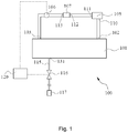
- FIG 1 is a block diagram for the connections of the components of the reflow oven (100) in the present application.
- the reflow oven in the present application comprises a reflow oven hearth (101), a separator (105), a zeolite box (107) and a sensor (106).
- a gas outlet (102) and a gas inlet (103) are provided on the reflow oven hearth (101).
- the separator (105) By connecting the gas outlet (102) to the separator inlet (110) of the separator (105) with a gas pipeline, the gases containing the flux can flow from the gas outlet (102) into the separator (105) and most of the flux can be removed by the separator (105).
- the separator (105) further has a separator outlet (111).
- the separator outlet (111) By connecting the separator outlet (111) to the zeolite box inlet (112) of the zeolite box (107) with a gas pipeline, the gases flowing through the separator (105) flow into the zeolite box (107) and then flow out of the zeolite box outlet (113) of the zeolite box (107). The residual flux in the gases is removed by the zeolite box (107).
- the sensor (106) is provided in the gas pipeline between the zeolite box outlet (113) and the gas inlet (103) of the reflow oven hearth. In this way, after the gases in which the flux is completely removed flow out of the zeolite box outlet (113), the oxygen concentration in the gases is first detected by the sensor (106) and a detection signal is obtained. After that, the gases are transported to the reflow oven hearth (101) via the gas inlet (103). Said gas pipeline can equally be replaced with another type of duct or a similar passage.
- the reflow oven (100) further comprises a nitrogen regulating passage (115), a nitrogen regulating valve (116) and a control device (120).
- a nitrogen regulating passage (115) With one end of the nitrogen regulating passage (115) connected to the nitrogen inlet (131) on the reflow oven hearth (101) and the other end connected to a nitrogen source (117), the nitrogen regulating passage (115) is used to supply nitrogen to the reflow oven hearth (101).
- the nitrogen regulating valve (116) is located in the nitrogen regulating passage (115), and the control device (120) controls the nitrogen regulating valve (116) so as to control the amount of nitrogen supplied to the reflow oven hearth (101).
- the control device (120) receives a detection signal indicating the oxygen concentration from the sensor (106), and determines according to the detection signal whether a proper amount of nitrogen needs to be supplied to the reflow oven hearth (101) so as to guarantee that the preset ratio of nitrogen to oxygen in the reflow oven hearth (101) is maintained.
- the working process of the reflow oven (100) in the present application is as follows: After soldering starts in the reflow oven, the flux vapors produced are mixed with nitrogen and oxygen to form gases containing the flux component, the gases flow out of the gas outlet (102), most of the flux is removed by use of the separation process in the separator (105), the remaining flux is further removed by use of the flowing filtering process in the zeolite box (107), and finally the gases return to the reflow oven hearth (101) via the gas inlet (103) to continue participating in soldering in the reflow oven.
- the oxygen concentration in the gases is first detected by the sensor (106), and the control device (120) regulates the nitrogen regulating valve (116) according to the detection result to control the amount of nitrogen supplied from the nitrogen source (117) to the reflow oven hearth (101) to maintain the ratio of nitrogen to oxygen in the reflow oven hearth (101) and guarantee the soldering effect during soldering.
- Different separation processes for example, flux condensation or flux decomposition
- flux decomposition is used in the separator (105) in the present application to remove the flux, and thus the gases flowing out of the separator (105) after separation contain only a low-content flux.
- the content of the residual flux in the gases flowing out of the separator (105) after separation is 10%, and only a trace of residual flux or no residual flux can be detected in the gases flowing out of the zeolite box (107) after filtering.
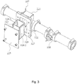
- FIG 2 shows the specific structure of the zeolite box (107) in the present application.
- the zeolite box inlet (112) shown in Figure 5 ) of the zeolite box (107) is used to connect to the separator outlet (111) (not shown in the figure, see Figure 1 ) with a gas pipeline, and the zeolite box outlet (113) (shown in Figure 5 ) of the zeolite box (107) is connected to the sensor (106).
- the zeolite box (107) comprises a box body (221), a box cover (225), and an inner net cage (323) (shown in Figure 3 ) accommodated in the box body (221).
- FIG 3 shows an exploded partial view of the zeolite box (107) in Figure 2 .
- the box body (221) has a chamber (322) used to accommodate the inner net cage (323).
- the inner net cage (323) contains zeolites (538) (as shown in Figure 5 ).
- the box body (221) has an opening (329) on one side so that the inner net cage (323) can be assembled or removed through the opening (329).
- the box cover (225) is used to seal the opening (329).
- a sealing gasket (327) is provided between the box body (221) and the box cover (225).
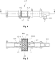
- Figure 4 is a top view of the reflow oven in Figure 2 and is used to show more detailed external installation structures of the zeolite box.
- Figure 5 is a cutaway view in the A-A direction in Figure 4 and is used to show more detailed internal installation structures of the zeolite box and show more clearly the zeolite box inlet (112) and the zeolite box outlet (113) of the zeolite box (107).
- a sleeve (537) is provided at the zeolite box inlet (112) and the zeolite box outlet (113), respectively.
- the zeolite box inlet (112) and the zeolite box outlet (113) can be sleeved in the gas pipeline and the sleeved positions can be fastened by use of a clasp or a clamp.
- the gases can be sealed more tightly when they flow from the separator outlet (111) to the zeolite box (107) and from the zeolite box (107) to the sensor (106).
- said zeolites (538) in the present application can be particles in the shape of a polygon, and a clearance (536) is formed between the particles to allow the gases to flow through when a plurality of particle zeolites (538) in the shape of a polygon are piled up together.
- the clearance (536) should be as large as possible so that the gases can encounter a small resistance when they flow through the zeolite box (107).
- the average particle size of zeolites (538) is 2 cm or so and zeolites (538) in such a size can cooperate with the inner net cage (323) to let the pressure of the gases flowing through the zeolite box (107) reach 1 kPa to 2 kPa and the velocity reach 15 m 3 /h.
- the flowing pressure of the gases is 1 kPa to 2 kPa and the flowing velocity is above 15 m 3 /h
- no additional fan or electric motor is required during the circulation of the gases, and the circulation of the gases can be realized by means of the negative pressure provided by the fan (not shown) in the reflow oven.
- fine cavities and passages are filled in the particles of zeolites (538) and the zeolites have a remarkable effect on the purification of the gases which flow out the separator (105) and contain a low-content flux.
- the inner net cage (323) is filled with zeolites (538).
- zeolites (538) To let the gases flow through the inner net cage (323) and enter the piles of zeolites (538), a series of gas openings are provided in at least two side walls (324.1 and 324.2) of the inner net cage (323) in the directions of the zeolite box inlet (112) and the zeolite box outlet (113) so that the gases can flow through the side walls (324.1 and 324.2).
- said gas openings should be in such a size that they allow the gases to flow through but prevent zeolites (538) from passing. In this way, zeolites (538) can be held in the inner net cage (323).
- Figure 6A and Figure 6B show two embodiments of side walls (324.1 and 324.2).
- side walls (324.1 and 324.2) are perforated plates, which have gas openings (628.1).
- side walls (324.1 and 324.2) are grid plates, which have gas openings (628.2).
- said gas openings (628.1 or 628.2) allow the gases to pass but prevent zeolites (538) from passing. Therefore, the size of said gas openings (628.1 or 628.2) should be determined according to the size of zeolites.
- the side walls (324.1 and 324.2) of the inner net cage (323) should have gas openings (628.1 or 628.2) as large as possible to minimize the resistance brought about by the inner net cage (323) to the flowing gases, and meanwhile, too large gas openings (628.1 or 628.2) should be prevented for fear that zeolites (538) can leak out of the gas openings (628.1 or 628.2).
- Gas openings can be provided only in the side walls (324.1 and 324.2) in the gas-flowing direction. However, gas openings can also be provided on the four side walls of the inner net cage (323) as long as the gas openings are in such a size that they can prevent zeolites (538) from passing.
- the remaining flux is removed by use of the flowing filtering process in the zeolite box (107).
- This is an optimized solution and structure for removing the remaining flux from the air, or specific inert gas, or a mixture of inert gases (for example, nitrogen and oxygen) in the reflow oven.
Landscapes
- Engineering & Computer Science (AREA)
- Mechanical Engineering (AREA)
- Electric Connection Of Electric Components To Printed Circuits (AREA)
- Waste-Gas Treatment And Other Accessory Devices For Furnaces (AREA)
- Processing Of Solid Wastes (AREA)
Claims (9)
- Reflow-Ofen, wobei der Reflow-Ofen einen Reflow-Ofenherd (101) umfasst und der Reflow-Ofenherd (101) einen Gasauslass (102) und einen Gaseinlass (103) umfasst, dadurch gekennzeichnet, dass der Reflow-Ofen ferner umfasst:
einen Separator (105), wobei der Separator (105) einen Separatoreinlass (110) und einen Separatorauslass (111) umfasst und der Separatoreinlass (110) mit dem Gasauslass (102) des Reflow-Ofenherdes (101) verbunden ist, sodass die Gase in dem Reflow-Ofenherd (101) in den Separator (105) strömen können, und gekennzeichnet durch:einen Zeolithkasten (107), wobei der Zeolithkasten (107) einen Zeolithkasteneinlass (112) und einen Zeolithkastenauslass (113) umfasst, wobei der Zeolithkasteneinlass (112) mit dem Separatorauslass (111) verbunden ist und der Zeolithkastenauslass (113) mit dem Gaseinlass (103) des Reflow-Ofenherdes (101) verbunden ist, sodass die Gase, die durch den Separator (105) strömen, in den Zeolithkasten (107) eintreten können und die Gase, die durch den Zeolithkasten (107) strömen, von dem Zeolithkastenauslass (113) zurück zu dem Reflow-Ofenherd (101) strömen können,wobei der Zeolithkasten (107) umfasst:einen Kastenkörper (221), wobei der Kastenkörper (221) eine Kammer (322) und eine Öffnung (329) aufweist,einen inneren Netzkäfig (323), wobei der innere Netzkäfig (323) abnehmbar in der Kammer (322) durch die Öffnung (329) befestigt ist, wobei Gasöffnungen (628.1 und 628.2) in mindestens zwei Seitenwänden (324.1 und 324.2) des inneren Netzkäfigs (323) vorgesehen sind, wobei der innere Netzkäfig (323) eine Vielzahl von Zeolithen (538) enthält und die Gasöffnungen (628.1 und 628.2) eine solche Größe aufweisen, dass sie die Vielzahl von Zeolithen (538) blockieren können, undeine Kastenabdeckung (225), wobei die Kastenabdeckung (225) die Öffnung (329) verschließt. - Reflow-Ofen nach Anspruch 1, dadurch gekennzeichnet, dass der Reflow-Ofen ferner umfasst:
einen Sensor (106), wobei der Sensor (106) in dem Gasdurchgang zwischen dem Zeolithkastenauslass (113) und dem Gaseinlass (103) des Reflow-Ofenherdes (101) vorgesehen ist. - Reflow-Ofen nach Anspruch 2, wobei ein Stickstoffeinlass (131) an dem Reflow-Ofenherd (101) vorgesehen ist, dadurch gekennzeichnet, dass der Reflow-Ofen ferner umfasst:ein Stickstoffregulierventil (116), wobei das Stickstoffregulierventil (116) mit dem Stickstoffeinlass (131) verbunden ist und verwendet wird, um die Menge an Eingangsstickstoff zu regulieren, undeine Steuervorrichtung (120), wobei die Steuervorrichtung (120) ein Erfassungssignal von dem Sensor (106) empfängt und das Stickstoffregulierventil (116) gemäß dem Erfassungssignal des Sensors (106) steuert.
- Reflow-Ofen nach Anspruch 1, dadurch gekennzeichnet, dass der Zeolith (538) die Form eines Polygons hat, sodass es einen Zwischenraum (536) zwischen der Vielzahl von Zeolithen (538) gibt.
- Reflow-Ofen nach Anspruch 4, dadurch gekennzeichnet, dass die durchschnittliche Teilchengröße der Vielzahl von Zeolithen (538) über 2 cm liegt.
- Reflow-Ofen nach Anspruch 1, dadurch gekennzeichnet, dass die mindestens zwei Seitenwände (324.1 und 324.2) des inneren Netzkäfigs (323) perforierte Platten sind.
- Verfahren zur Gasrückgewinnung eines Reflow-Ofens nach einem der Ansprüche 2-3, wobei der Reflow-Ofenherd (101) des Reflow-Ofens einen Gasauslass (102) und einen Gaseinlass (103) umfasst, dadurch gekennzeichnet, dass das Gasrückgewinnungsverfahren die folgenden Schritte umfasst:Ermöglichen, dass die Gase, die vom Gasauslass (102) des Reflow-Ofenherdes (101) ausgegeben werden, nacheinander durch den Separator (105) und den Zeolithkasten (107) strömen, sodass das Flussmittel aus den Gasen entfernt wird,Ermöglichen, dass die Gase durch den Sensor (106) strömen, um die Konzentration von Sauerstoff in den Gasen zu erfassen, undErmöglichen, dass die Gase von dem Gaseinlass (103) des Reflow-Ofenherdes (101) zurück zu dem Reflow-Ofenherd (101) strömen und die Menge an Stickstoff, die in den Reflow-Ofenherd (101) eingegeben wird, gemäß der Sauerstoffkonzentration, die durch den Sensor (106) erfasst wird, steuern.
- Verfahren nach Anspruch 7, dadurch gekennzeichnet, dass der Druck der durch den Zeolithkasten (107) strömenden Gase 1 kPa bis 2 kPa beträgt.
- Verfahren nach Anspruch 7, dadurch gekennzeichnet, dass die Geschwindigkeit der durch den Zeolithkasten (107) strömenden Gase 15 m3/h beträgt.
Applications Claiming Priority (3)
| Application Number | Priority Date | Filing Date | Title |
|---|---|---|---|
| CN201710726250.7A CN109420814A (zh) | 2017-08-22 | 2017-08-22 | 一种回流焊炉及气体回收方法 |
| CN201721056520.XU CN207289104U (zh) | 2017-08-22 | 2017-08-22 | 一种回流焊炉 |
| PCT/US2018/045899 WO2019040284A1 (en) | 2017-08-22 | 2018-08-09 | REFUELING OVEN WITH ZEOLITE BOX, AND METHOD FOR RECOVERING GAS WITH SUCH ZEOLITE BOX |
Publications (2)
| Publication Number | Publication Date |
|---|---|
| EP3672754A1 EP3672754A1 (de) | 2020-07-01 |
| EP3672754B1 true EP3672754B1 (de) | 2021-10-06 |
Family
ID=63405378
Family Applications (1)
| Application Number | Title | Priority Date | Filing Date |
|---|---|---|---|
| EP18760115.8A Active EP3672754B1 (de) | 2017-08-22 | 2018-08-09 | Reflow-ofen mit zeolithkasten und verfahren zur rückgewinnung von gas mit einer solchen zeolithbox |
Country Status (5)
| Country | Link |
|---|---|
| US (2) | US11440116B2 (de) |
| EP (1) | EP3672754B1 (de) |
| JP (1) | JP7227961B2 (de) |
| TW (1) | TWI779074B (de) |
| WO (1) | WO2019040284A1 (de) |
Family Cites Families (15)
| Publication number | Priority date | Publication date | Assignee | Title |
|---|---|---|---|---|
| JPH0697645A (ja) * | 1992-01-20 | 1994-04-08 | Tokyo Gas Co Ltd | リフローはんだ付け炉内の酸素濃度を減少させる方法及びその装置 |
| EP0934792A3 (de) * | 1992-11-17 | 2001-09-05 | Matsushita Electric Industrial Co., Ltd. | Verfahren und Vorrichtung zum Aufschmelzlöten |
| JPH07159297A (ja) * | 1993-12-08 | 1995-06-23 | Furukawa Electric Co Ltd:The | 不活性ガス雰囲気リフロー炉の酸素濃度測定装置 |
| WO2001028304A1 (en) * | 1999-10-14 | 2001-04-19 | Fujitsu Limited | Reflowing furnace |
| JP2007273571A (ja) * | 2006-03-30 | 2007-10-18 | Tamura Furukawa Machinery:Kk | リフロー炉 |
| JP4721352B2 (ja) * | 2006-06-09 | 2011-07-13 | 株式会社タムラ製作所 | リフロー炉 |
| CN101115357A (zh) * | 2006-07-26 | 2008-01-30 | 有限会社横田技术 | 回流焊接装置及焊剂回收装置 |
| WO2008047639A1 (fr) | 2006-10-11 | 2008-04-24 | Nikki-Universal Co., Ltd. | Catalyseur de purification pour un gaz à l'intérieur d'un four à fusion, procédé pour empêcher la contamination du four à fusion, et four à fusion |
| US8110015B2 (en) * | 2007-05-30 | 2012-02-07 | Illinois Tool Works, Inc. | Method and apparatus for removing contaminants from a reflow apparatus |
| DE102012220159B4 (de) | 2012-11-06 | 2019-06-27 | Ersa Gmbh | Verfahren und Reinigungssystem zur Reinigung des Prozessgases in Lötanlagen und Lötabsaugsystemen |
| BR102012032031A2 (pt) * | 2012-12-14 | 2014-09-09 | Air Liquide Brasil Ltda | Equipamento portátil para monitoramento e controle do nível de oxigênio em atmosfera de fornos de refusão |
| EP3053691A1 (de) * | 2015-02-04 | 2016-08-10 | Illinois Tool Works Inc. | Reflow Lötofen mit verbessertem Gasreinigungssystem |
| US20160339486A1 (en) * | 2015-05-21 | 2016-11-24 | Illinois Tool Works Inc. | Reflow oven liner, system and method |
| CN106695048A (zh) | 2016-12-21 | 2017-05-24 | 通富微电子股份有限公司 | 一种回流焊炉及其控制系统 |
| CN207289104U (zh) | 2017-08-22 | 2018-05-01 | 伊利诺斯工具制品有限公司 | 一种回流焊炉 |
-
2018
- 2018-08-06 TW TW107127245A patent/TWI779074B/zh active
- 2018-08-09 JP JP2020511316A patent/JP7227961B2/ja active Active
- 2018-08-09 WO PCT/US2018/045899 patent/WO2019040284A1/en not_active Ceased
- 2018-08-09 US US16/640,153 patent/US11440116B2/en active Active
- 2018-08-09 EP EP18760115.8A patent/EP3672754B1/de active Active
-
2022
- 2022-09-09 US US17/941,316 patent/US12064828B2/en active Active
Also Published As
| Publication number | Publication date |
|---|---|
| US20210078091A1 (en) | 2021-03-18 |
| JP7227961B2 (ja) | 2023-02-22 |
| TW201912279A (zh) | 2019-04-01 |
| US11440116B2 (en) | 2022-09-13 |
| EP3672754A1 (de) | 2020-07-01 |
| JP2020531289A (ja) | 2020-11-05 |
| TWI779074B (zh) | 2022-10-01 |
| US20230001498A1 (en) | 2023-01-05 |
| WO2019040284A1 (en) | 2019-02-28 |
| US12064828B2 (en) | 2024-08-20 |
Similar Documents
| Publication | Publication Date | Title |
|---|---|---|
| CN207289104U (zh) | 一种回流焊炉 | |
| US6808554B2 (en) | Filtering apparatus | |
| EP3781886B1 (de) | Reflow-ofen und betriebsverfahren dafür | |
| US20030218058A1 (en) | Reflow oven gas management system and method | |
| US12364945B2 (en) | Exhaust gas purification device | |
| EP3844448B1 (de) | Ein kühlsystem für einen reflow-ofen | |
| CN107530809A (zh) | 具有至少一个含有催化剂单元的气体净化系统的回流焊接炉 | |
| US5911486A (en) | Combination product cooling and flux management apparatus | |
| US20240230232A1 (en) | Gas control system for reflow furnace and reflow furnace | |
| US20230001498A1 (en) | Reflow oven with a zeolite box, and a method for recovering gas with such zeolite box | |
| JPH07507759A (ja) | 工業用炉およびその運転方法 | |
| CN111054175B (zh) | 废气净化装置 | |
| CN111054174B (zh) | 废气净化装置 | |
| JP2021522998A (ja) | リフロー炉の排ガスフィルター | |
| WO2020218122A1 (ja) | 加熱装置及びはんだ接合済対象物の製造方法 | |
| US20140007910A1 (en) | Apparatus and method for cross-flow purge for optical components in a chamber | |
| RU2851214C1 (ru) | Система газовой рекуперации установки селективного лазерного сплавления | |
| CN118023646A (zh) | 氧气浓度检测系统及使用其的回流焊炉 | |
| JP4124382B2 (ja) | 吸着済吸着剤の燃焼装置 | |
| WO2020081273A1 (en) | Device for cleaning the waste gas of a furnace chamber of a reflow soldering furnace | |
| JP2009236471A (ja) | 熱処理装置 | |
| US20190187111A1 (en) | Flow controller and gas chromatograph equipped with the same | |
| CN117283076A (zh) | 用于回流焊炉的气体净化装置和使用该气体净化装置的回流焊炉 | |
| JPH0621644A (ja) | 温度制御の良いリフロー炉 | |
| CN117258495A (zh) | 一种低浓度废气浓缩系统和方法 |
Legal Events
| Date | Code | Title | Description |
|---|---|---|---|
| STAA | Information on the status of an ep patent application or granted ep patent |
Free format text: STATUS: UNKNOWN |
|
| STAA | Information on the status of an ep patent application or granted ep patent |
Free format text: STATUS: THE INTERNATIONAL PUBLICATION HAS BEEN MADE |
|
| PUAI | Public reference made under article 153(3) epc to a published international application that has entered the european phase |
Free format text: ORIGINAL CODE: 0009012 |
|
| STAA | Information on the status of an ep patent application or granted ep patent |
Free format text: STATUS: REQUEST FOR EXAMINATION WAS MADE |
|
| 17P | Request for examination filed |
Effective date: 20200221 |
|
| AK | Designated contracting states |
Kind code of ref document: A1 Designated state(s): AL AT BE BG CH CY CZ DE DK EE ES FI FR GB GR HR HU IE IS IT LI LT LU LV MC MK MT NL NO PL PT RO RS SE SI SK SM TR |
|
| AX | Request for extension of the european patent |
Extension state: BA ME |
|
| DAV | Request for validation of the european patent (deleted) | ||
| DAX | Request for extension of the european patent (deleted) | ||
| GRAP | Despatch of communication of intention to grant a patent |
Free format text: ORIGINAL CODE: EPIDOSNIGR1 |
|
| STAA | Information on the status of an ep patent application or granted ep patent |
Free format text: STATUS: GRANT OF PATENT IS INTENDED |
|
| INTG | Intention to grant announced |
Effective date: 20210319 |
|
| GRAS | Grant fee paid |
Free format text: ORIGINAL CODE: EPIDOSNIGR3 |
|
| GRAA | (expected) grant |
Free format text: ORIGINAL CODE: 0009210 |
|
| STAA | Information on the status of an ep patent application or granted ep patent |
Free format text: STATUS: THE PATENT HAS BEEN GRANTED |
|
| AK | Designated contracting states |
Kind code of ref document: B1 Designated state(s): AL AT BE BG CH CY CZ DE DK EE ES FI FR GB GR HR HU IE IS IT LI LT LU LV MC MK MT NL NO PL PT RO RS SE SI SK SM TR |
|
| REG | Reference to a national code |
Ref country code: GB Ref legal event code: FG4D |
|
| REG | Reference to a national code |
Ref country code: CH Ref legal event code: EP Ref country code: AT Ref legal event code: REF Ref document number: 1435793 Country of ref document: AT Kind code of ref document: T Effective date: 20211015 |
|
| REG | Reference to a national code |
Ref country code: DE Ref legal event code: R096 Ref document number: 602018024697 Country of ref document: DE |
|
| REG | Reference to a national code |
Ref country code: IE Ref legal event code: FG4D |
|
| REG | Reference to a national code |
Ref country code: LT Ref legal event code: MG9D |
|
| REG | Reference to a national code |
Ref country code: NL Ref legal event code: MP Effective date: 20211006 |
|
| REG | Reference to a national code |
Ref country code: AT Ref legal event code: MK05 Ref document number: 1435793 Country of ref document: AT Kind code of ref document: T Effective date: 20211006 |
|
| PG25 | Lapsed in a contracting state [announced via postgrant information from national office to epo] |
Ref country code: RS Free format text: LAPSE BECAUSE OF FAILURE TO SUBMIT A TRANSLATION OF THE DESCRIPTION OR TO PAY THE FEE WITHIN THE PRESCRIBED TIME-LIMIT Effective date: 20211006 Ref country code: LT Free format text: LAPSE BECAUSE OF FAILURE TO SUBMIT A TRANSLATION OF THE DESCRIPTION OR TO PAY THE FEE WITHIN THE PRESCRIBED TIME-LIMIT Effective date: 20211006 Ref country code: FI Free format text: LAPSE BECAUSE OF FAILURE TO SUBMIT A TRANSLATION OF THE DESCRIPTION OR TO PAY THE FEE WITHIN THE PRESCRIBED TIME-LIMIT Effective date: 20211006 Ref country code: BG Free format text: LAPSE BECAUSE OF FAILURE TO SUBMIT A TRANSLATION OF THE DESCRIPTION OR TO PAY THE FEE WITHIN THE PRESCRIBED TIME-LIMIT Effective date: 20220106 Ref country code: AT Free format text: LAPSE BECAUSE OF FAILURE TO SUBMIT A TRANSLATION OF THE DESCRIPTION OR TO PAY THE FEE WITHIN THE PRESCRIBED TIME-LIMIT Effective date: 20211006 |
|
| PG25 | Lapsed in a contracting state [announced via postgrant information from national office to epo] |
Ref country code: IS Free format text: LAPSE BECAUSE OF FAILURE TO SUBMIT A TRANSLATION OF THE DESCRIPTION OR TO PAY THE FEE WITHIN THE PRESCRIBED TIME-LIMIT Effective date: 20220206 Ref country code: SE Free format text: LAPSE BECAUSE OF FAILURE TO SUBMIT A TRANSLATION OF THE DESCRIPTION OR TO PAY THE FEE WITHIN THE PRESCRIBED TIME-LIMIT Effective date: 20211006 Ref country code: PT Free format text: LAPSE BECAUSE OF FAILURE TO SUBMIT A TRANSLATION OF THE DESCRIPTION OR TO PAY THE FEE WITHIN THE PRESCRIBED TIME-LIMIT Effective date: 20220207 Ref country code: PL Free format text: LAPSE BECAUSE OF FAILURE TO SUBMIT A TRANSLATION OF THE DESCRIPTION OR TO PAY THE FEE WITHIN THE PRESCRIBED TIME-LIMIT Effective date: 20211006 Ref country code: NO Free format text: LAPSE BECAUSE OF FAILURE TO SUBMIT A TRANSLATION OF THE DESCRIPTION OR TO PAY THE FEE WITHIN THE PRESCRIBED TIME-LIMIT Effective date: 20220106 Ref country code: NL Free format text: LAPSE BECAUSE OF FAILURE TO SUBMIT A TRANSLATION OF THE DESCRIPTION OR TO PAY THE FEE WITHIN THE PRESCRIBED TIME-LIMIT Effective date: 20211006 Ref country code: LV Free format text: LAPSE BECAUSE OF FAILURE TO SUBMIT A TRANSLATION OF THE DESCRIPTION OR TO PAY THE FEE WITHIN THE PRESCRIBED TIME-LIMIT Effective date: 20211006 Ref country code: HR Free format text: LAPSE BECAUSE OF FAILURE TO SUBMIT A TRANSLATION OF THE DESCRIPTION OR TO PAY THE FEE WITHIN THE PRESCRIBED TIME-LIMIT Effective date: 20211006 Ref country code: GR Free format text: LAPSE BECAUSE OF FAILURE TO SUBMIT A TRANSLATION OF THE DESCRIPTION OR TO PAY THE FEE WITHIN THE PRESCRIBED TIME-LIMIT Effective date: 20220107 Ref country code: ES Free format text: LAPSE BECAUSE OF FAILURE TO SUBMIT A TRANSLATION OF THE DESCRIPTION OR TO PAY THE FEE WITHIN THE PRESCRIBED TIME-LIMIT Effective date: 20211006 |
|
| REG | Reference to a national code |
Ref country code: DE Ref legal event code: R097 Ref document number: 602018024697 Country of ref document: DE |
|
| PG25 | Lapsed in a contracting state [announced via postgrant information from national office to epo] |
Ref country code: SM Free format text: LAPSE BECAUSE OF FAILURE TO SUBMIT A TRANSLATION OF THE DESCRIPTION OR TO PAY THE FEE WITHIN THE PRESCRIBED TIME-LIMIT Effective date: 20211006 Ref country code: SK Free format text: LAPSE BECAUSE OF FAILURE TO SUBMIT A TRANSLATION OF THE DESCRIPTION OR TO PAY THE FEE WITHIN THE PRESCRIBED TIME-LIMIT Effective date: 20211006 Ref country code: RO Free format text: LAPSE BECAUSE OF FAILURE TO SUBMIT A TRANSLATION OF THE DESCRIPTION OR TO PAY THE FEE WITHIN THE PRESCRIBED TIME-LIMIT Effective date: 20211006 Ref country code: EE Free format text: LAPSE BECAUSE OF FAILURE TO SUBMIT A TRANSLATION OF THE DESCRIPTION OR TO PAY THE FEE WITHIN THE PRESCRIBED TIME-LIMIT Effective date: 20211006 Ref country code: DK Free format text: LAPSE BECAUSE OF FAILURE TO SUBMIT A TRANSLATION OF THE DESCRIPTION OR TO PAY THE FEE WITHIN THE PRESCRIBED TIME-LIMIT Effective date: 20211006 Ref country code: CZ Free format text: LAPSE BECAUSE OF FAILURE TO SUBMIT A TRANSLATION OF THE DESCRIPTION OR TO PAY THE FEE WITHIN THE PRESCRIBED TIME-LIMIT Effective date: 20211006 |
|
| PLBE | No opposition filed within time limit |
Free format text: ORIGINAL CODE: 0009261 |
|
| STAA | Information on the status of an ep patent application or granted ep patent |
Free format text: STATUS: NO OPPOSITION FILED WITHIN TIME LIMIT |
|
| 26N | No opposition filed |
Effective date: 20220707 |
|
| PG25 | Lapsed in a contracting state [announced via postgrant information from national office to epo] |
Ref country code: AL Free format text: LAPSE BECAUSE OF FAILURE TO SUBMIT A TRANSLATION OF THE DESCRIPTION OR TO PAY THE FEE WITHIN THE PRESCRIBED TIME-LIMIT Effective date: 20211006 |
|
| PG25 | Lapsed in a contracting state [announced via postgrant information from national office to epo] |
Ref country code: SI Free format text: LAPSE BECAUSE OF FAILURE TO SUBMIT A TRANSLATION OF THE DESCRIPTION OR TO PAY THE FEE WITHIN THE PRESCRIBED TIME-LIMIT Effective date: 20211006 |
|
| PG25 | Lapsed in a contracting state [announced via postgrant information from national office to epo] |
Ref country code: MC Free format text: LAPSE BECAUSE OF FAILURE TO SUBMIT A TRANSLATION OF THE DESCRIPTION OR TO PAY THE FEE WITHIN THE PRESCRIBED TIME-LIMIT Effective date: 20211006 |
|
| REG | Reference to a national code |
Ref country code: CH Ref legal event code: PL |
|
| GBPC | Gb: european patent ceased through non-payment of renewal fee |
Effective date: 20220809 |
|
| PG25 | Lapsed in a contracting state [announced via postgrant information from national office to epo] |
Ref country code: LU Free format text: LAPSE BECAUSE OF NON-PAYMENT OF DUE FEES Effective date: 20220809 Ref country code: LI Free format text: LAPSE BECAUSE OF NON-PAYMENT OF DUE FEES Effective date: 20220831 Ref country code: CH Free format text: LAPSE BECAUSE OF NON-PAYMENT OF DUE FEES Effective date: 20220831 |
|
| REG | Reference to a national code |
Ref country code: BE Ref legal event code: MM Effective date: 20220831 |
|
| PG25 | Lapsed in a contracting state [announced via postgrant information from national office to epo] |
Ref country code: IT Free format text: LAPSE BECAUSE OF FAILURE TO SUBMIT A TRANSLATION OF THE DESCRIPTION OR TO PAY THE FEE WITHIN THE PRESCRIBED TIME-LIMIT Effective date: 20211006 |
|
| P01 | Opt-out of the competence of the unified patent court (upc) registered |
Effective date: 20230606 |
|
| PG25 | Lapsed in a contracting state [announced via postgrant information from national office to epo] |
Ref country code: IE Free format text: LAPSE BECAUSE OF NON-PAYMENT OF DUE FEES Effective date: 20220809 Ref country code: FR Free format text: LAPSE BECAUSE OF NON-PAYMENT OF DUE FEES Effective date: 20220831 |
|
| PG25 | Lapsed in a contracting state [announced via postgrant information from national office to epo] |
Ref country code: BE Free format text: LAPSE BECAUSE OF NON-PAYMENT OF DUE FEES Effective date: 20220831 |
|
| PG25 | Lapsed in a contracting state [announced via postgrant information from national office to epo] |
Ref country code: GB Free format text: LAPSE BECAUSE OF NON-PAYMENT OF DUE FEES Effective date: 20220809 |
|
| PG25 | Lapsed in a contracting state [announced via postgrant information from national office to epo] |
Ref country code: CY Free format text: LAPSE BECAUSE OF FAILURE TO SUBMIT A TRANSLATION OF THE DESCRIPTION OR TO PAY THE FEE WITHIN THE PRESCRIBED TIME-LIMIT Effective date: 20211006 |
|
| PG25 | Lapsed in a contracting state [announced via postgrant information from national office to epo] |
Ref country code: MK Free format text: LAPSE BECAUSE OF FAILURE TO SUBMIT A TRANSLATION OF THE DESCRIPTION OR TO PAY THE FEE WITHIN THE PRESCRIBED TIME-LIMIT Effective date: 20211006 Ref country code: HU Free format text: LAPSE BECAUSE OF FAILURE TO SUBMIT A TRANSLATION OF THE DESCRIPTION OR TO PAY THE FEE WITHIN THE PRESCRIBED TIME-LIMIT; INVALID AB INITIO Effective date: 20180809 |
|
| PG25 | Lapsed in a contracting state [announced via postgrant information from national office to epo] |
Ref country code: TR Free format text: LAPSE BECAUSE OF FAILURE TO SUBMIT A TRANSLATION OF THE DESCRIPTION OR TO PAY THE FEE WITHIN THE PRESCRIBED TIME-LIMIT Effective date: 20211006 |
|
| PG25 | Lapsed in a contracting state [announced via postgrant information from national office to epo] |
Ref country code: MT Free format text: LAPSE BECAUSE OF FAILURE TO SUBMIT A TRANSLATION OF THE DESCRIPTION OR TO PAY THE FEE WITHIN THE PRESCRIBED TIME-LIMIT Effective date: 20211006 |
|
| PGFP | Annual fee paid to national office [announced via postgrant information from national office to epo] |
Ref country code: DE Payment date: 20250827 Year of fee payment: 8 |