EP3672504B1 - Steuersystem für eine medizinische retrograde bohrvorrichtung - Google Patents
Steuersystem für eine medizinische retrograde bohrvorrichtung Download PDFInfo
- Publication number
- EP3672504B1 EP3672504B1 EP18848385.3A EP18848385A EP3672504B1 EP 3672504 B1 EP3672504 B1 EP 3672504B1 EP 18848385 A EP18848385 A EP 18848385A EP 3672504 B1 EP3672504 B1 EP 3672504B1
- Authority
- EP
- European Patent Office
- Prior art keywords
- blade
- cam
- inner shaft
- longitudinal axis
- elongated body
- Prior art date
- Legal status (The legal status is an assumption and is not a legal conclusion. Google has not performed a legal analysis and makes no representation as to the accuracy of the status listed.)
- Active
Links
Images


Classifications
-
- A—HUMAN NECESSITIES
- A61—MEDICAL OR VETERINARY SCIENCE; HYGIENE
- A61B—DIAGNOSIS; SURGERY; IDENTIFICATION
- A61B17/00—Surgical instruments, devices or methods
- A61B17/16—Instruments for performing osteoclasis; Drills or chisels for bones; Trepans
- A61B17/1613—Component parts
- A61B17/1615—Drill bits, i.e. rotating tools extending from a handpiece to contact the worked material
- A61B17/1617—Drill bits, i.e. rotating tools extending from a handpiece to contact the worked material with mobile or detachable parts
-
- A—HUMAN NECESSITIES
- A61—MEDICAL OR VETERINARY SCIENCE; HYGIENE
- A61B—DIAGNOSIS; SURGERY; IDENTIFICATION
- A61B17/00—Surgical instruments, devices or methods
- A61B17/16—Instruments for performing osteoclasis; Drills or chisels for bones; Trepans
- A61B17/1613—Component parts
- A61B17/162—Chucks or tool parts which are to be held in a chuck
-
- A—HUMAN NECESSITIES
- A61—MEDICAL OR VETERINARY SCIENCE; HYGIENE
- A61B—DIAGNOSIS; SURGERY; IDENTIFICATION
- A61B17/00—Surgical instruments, devices or methods
- A61B17/16—Instruments for performing osteoclasis; Drills or chisels for bones; Trepans
- A61B17/1613—Component parts
- A61B17/1622—Drill handpieces
- A61B17/1624—Drive mechanisms therefor
-
- A—HUMAN NECESSITIES
- A61—MEDICAL OR VETERINARY SCIENCE; HYGIENE
- A61B—DIAGNOSIS; SURGERY; IDENTIFICATION
- A61B17/00—Surgical instruments, devices or methods
- A61B17/16—Instruments for performing osteoclasis; Drills or chisels for bones; Trepans
- A61B17/1613—Component parts
- A61B17/1626—Control means; Display units
-
- A—HUMAN NECESSITIES
- A61—MEDICAL OR VETERINARY SCIENCE; HYGIENE
- A61B—DIAGNOSIS; SURGERY; IDENTIFICATION
- A61B17/00—Surgical instruments, devices or methods
- A61B17/16—Instruments for performing osteoclasis; Drills or chisels for bones; Trepans
- A61B17/1613—Component parts
- A61B17/1631—Special drive shafts, e.g. flexible shafts
-
- A—HUMAN NECESSITIES
- A61—MEDICAL OR VETERINARY SCIENCE; HYGIENE
- A61B—DIAGNOSIS; SURGERY; IDENTIFICATION
- A61B17/00—Surgical instruments, devices or methods
- A61B17/16—Instruments for performing osteoclasis; Drills or chisels for bones; Trepans
- A61B17/1662—Instruments for performing osteoclasis; Drills or chisels for bones; Trepans for particular parts of the body
- A61B17/1675—Instruments for performing osteoclasis; Drills or chisels for bones; Trepans for particular parts of the body for the knee
-
- A—HUMAN NECESSITIES
- A61—MEDICAL OR VETERINARY SCIENCE; HYGIENE
- A61B—DIAGNOSIS; SURGERY; IDENTIFICATION
- A61B17/00—Surgical instruments, devices or methods
- A61B2017/00367—Details of actuation of instruments, e.g. relations between pushing buttons, or the like, and activation of the tool, working tip, or the like
Definitions
- the invention relates to rotary cutting devices useful in arthroscopy, and more particularly, to flip retrograde cutting devices for drilling of sockets and tunnels for ACL reconstruction.
- a small incision is made in the skin covering the arthroscopic site or joint, and a cannula is inserted in the incision to provide a pathway for surgical devices to be placed in the joint and manipulated through arthroscopic visualization.
- Surgical devices inserted through cannulas must be long and thin, which creates limitations on devices for cutting tissue, as the diameter of the cannula ordinarily limits the width of the cutting implement.
- Flip cutters have been used for retrograde drilling of sockets and tunnels for ACL reconstruction.
- the flip cutters have a blade, preferably a flip blade, that is configured to articulate between at least a first "straight" position, for example, substantially parallel to a longitudinal axis of the flip retrograde cutter, and at least a second "flip" position, for example, a non-parallel position relative to the longitudinal axis of the flip retrograde cutter.
- a recipient site socket can be created from the inside out using a retrograde technique with minimal incisions of distal cortices and reduced intraarticular bone fragmentation of tunnel rims.
- the blades of the flip cutters have been moved manually between the first and second positions to enable retrograde drilling of sockets and tunnels. A more efficient system for retaining in position and moving the blade of a flip cutter is needed.
- WO 2017/137998 A2 discloses a rotary cutting device with the features of the preamble of claim 1.
- connection system connecting the inner shaft to the blade comprises a pin and a slot that allow conversion of linear movement of the inner shaft into rotational movement of the blade to rotate the blade to the second, flip position upon linear movement of the inner shaft in relation to the outer tube the pin sliding in the slot to permit rotation of the blade, and wherein the blade is articulated to a nonparallel position relative to the longitudinal axis of the elongated body when the blade is in the second, flip position, and wherein the second, flip position, the cutting arris of the blade is exposed toward the proximal end of the elongated body for retrograde drilling of a hole when the blade is locked in the second, flip position.
- a rotary, cutting medical device configured to be used during surgeries, such as ACL reconstruction, to drill holes and retrograde sockets.
- the device includes a blade at a distal end that is movable between a first position aligned with a longitudinal axis of the device and a second position nonparallel to the longitudinal axis used to create retrograde sockets.
- the device includes a connection system connecting the inner shaft to the blade such that blade is movable between first and second positions for drilling a hole and then creating a retrograde socket.
- the device includes a position retention system configured to retain the blade in the second position for creating a retrograde socket.
- the position retention system retains the blade in the second position while allowing the outer tube, inner shaft and blade to rotate to cut the socket.
- the position retention system prevents the blade from inadvertently returning to the first position, which is aligned with the longitudinal axis, when the blade encounters heavy resistance drilling through bone.
- the rotary cutting device is formed from an elongated body having a distal end, a proximal end, and a longitudinal axis.
- the elongated body also includes an outer tube and an inner shaft housed by the outer tube.
- the device includes a blade at the distal end of the body, wherein the blade is configured to rotate from a first position generally aligned with the longitudinal axis to a second, flip position which is nonparallel with the longitudinal axis.
- the device includes a blade position control system connecting the blade to distal ends of both the outer tube and inner shaft.
- the blade position control system includes a connection system connecting the inner shaft to the blade that allows the blade to move from the first position generally aligned with the longitudinal axis to the second, flip position which is nonparallel with the longitudinal axis and a cutting arris of the blade is exposed toward the proximal end of the elongated body for retrograde drilling of a hole when the blade is locked in the second, flip position.
- the blade position control system includes a cam in communication with a cam follower and in communication with the inner shaft for moving the blade into first and second positions.
- the blade position control system also includes a position retention system configured to retain the cam in a second position such that the inner shaft is retained in the second position, thereby retaining the cutting arris of the blade in position such that the cutting arris is exposed toward the proximal end of the elongated body while allowing the inner shaft and blade to rotate for retrograde drilling of a hole.
- the position retention system may be configured such that the position retention system may include one or more pins extending from the cam.
- the position retention system may include one or more grooves on the inner shaft for receiving the pin extending from the cam such that the inner shaft is rotatable while the pin resides in the groove on the inner shaft, thereby preventing axial movement of the inner shaft.
- the position retention system may include one or more slots in the cam for receiving the pin to account for potential misalignment between the pin, cam and groove on the inner shaft.
- the cam of the blade position control system may be formed from a first head member and a second head member separated by a tube receiving chamber configured to receive the inner shaft extending therethrough.
- the cam follower includes a first position retainer configured to retain the cam in a first position, which also retains the blade in a position generally aligned with the longitudinal axis.
- the cam follower also includes a second position retainer configured to retain the cam in a second position in which the cutting arris of the blade is positioned such that the cutting arris is exposed toward the proximal end of the elongated body for retrograde drilling of a hole while allowing the inner shaft and blade to rotate.
- the first position retainer may be formed from a nonlinear engaging surface with a concave detent configured to hold the cam in a first position, which also retains the blade in a position generally aligned with the longitudinal axis.
- the engaging surface of the cam follower between the first and second position retainers may be non orthogonal relative to the longitudinal axis of the elongated body.
- the second position retainer may be formed from a flat surface generally orthogonal to the longitudinal axis of the elongated body. The second position retainer may be positioned closer to the distal end of the elongated body than the first position retainer.
- the device may also include a housing configured to retain the cam in position whereby the housing includes an inner side surface that houses the cam to prevent the cam from being inadvertently displaced and to limit rotation of the cam about only one axis.
- the device may also include a biasing mechanism configured to bias the cam follower towards the cam to keep the cam follower in contact with the cam and configured to bias the inner shaft toward the distal end of the elongated body.
- the device may include a drive hub positioned at the proximal end and configured to place the inner shaft in mechanical communication with a handpiece to impart rotary motion to the inner shaft and blade, as controlled by controls on the handpiece.
- connection system connecting the inner shaft to the blade may be formed from a pin and a slot that allow conversion of linear movement of the inner shaft into rotational movement of the blade to rotate the blade to the second, flip position.
- the blade rotates to the second, flip position upon linear movement of the inner shaft in relation to the outer tube the pin sliding in the slot to permit rotation of the blade.
- the blade is articulated to a nonparallel position relative to the longitudinal axis of the elongated body.
- a cutting arris of the blade is exposed toward the proximal end of the elongated body for retrograde drilling of a hole.
- An advantage of the device is that a user, such as, but not limited to, a surgeon, may use the handpiece to create retrograde sockets without the blade inadvertently popping out of position and requiring the blade to be repositioned before continuing to drill a retrograde socket.
- position retention system prevents any lateral movement, thereby preventing the blade from inadvertently popping out of position, while enabling rotary motion to enable the blade to be rotated to cut bone.
- the blade position control system moves the blade between a first positioned generally aligned with a longitudinal axis of the elongated body to a second flipped position in which the blade is nonparallel with the longitudinal axis and positioned to create retrograde sockets.
- the blade control system may be controlled by a user, such as, but not limited to, a surgeon, via a single lever.
- Still another advantage of the device is that the position retention system improves the safety of the device because the position retention system, outer hub and lever arm do not spin; rather, only the inner shaft spins, and in at least one embodiment, only the inner shaft and outer tube spin.
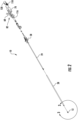
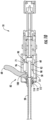
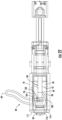
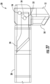
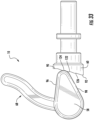
- a rotary, cutting medical device 10 configured to be used during surgeries, such as ACL reconstruction, to drill holes and retrograde sockets.
- the device 10 may include a blade 12 at a distal end 14 that is movable between a first position 16 aligned with a longitudinal axis 18 of the device 10 and a second position 20 nonparallel to the longitudinal axis 18 used to create retrograde sockets 32 and tunnels.
- the device 10 may include a connection system 22 connecting an inner shaft 24 to the blade 12 such that blade 12 is movable between first and second positions 16, 20, as shown in Figures 15-27 for drilling a hole 24 and then creating a retrograde socket 32 or tunnel.
- the device 10 may include a blade position control system 26 connecting the blade 12 to distal ends 15, 17 of both the outer tube 28 and inner shaft 24 and configured to control movement of the blade 12 between first and second positions 16, 20 for drilling a hole 30 and then creating a retrograde socket 32 or tunnel.
- the device 10 may include a position retention system 34, as shown in Figures 7 and 9-13 , configured to retain the blade 12 in the second position 20, as shown in Figures 16 , 20 and 25-27 , for creating a retrograde socket 32 or tunnel.
- the position retention system 34 retains the blade 12 in the second position 20 while allowing the inner shaft 24 and blade 12 to rotate to cut the socket.
- the position retention system 34 prevents the blade 12 from inadvertently returning to the first position 16, which is aligned with the longitudinal axis 18, when the blade 12 encounters heavy resistance drilling through bone.
- the rotary cutting device 10 may be formed from an elongated body 36 having a distal end 14, a proximal end 38, and a longitudinal axis 18.
- the elongated body 36 may also include the outer tube 28 and the inner shaft 24 housed by the outer tube 28.
- the inner and outer tubes 24, 28 may be formed from materials such as, but not limited to, 17-4 ph or 17-7 ph stainless steel.
- the inner shaft 24 may be sized to fit within the outer tube 28 while generally being aligned with the outer tube 28.
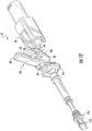
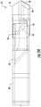
- the device 10 may include a blade 12 at the distal end 14 of the body 36.
- the blade 12 may be configured to rotate from the first position 16 generally aligned with the longitudinal axis to a second, flip position 20 which is nonparallel with the longitudinal axis 18.
- the first position 16 may be about 0 degrees.
- the blade 12 positioned in the second, flip position 20 may be positioned generally orthogonal to the blade 12 in the first position 16.
- the blade 12 positioned in the second, flip position 20 may be positioned generally 90 degrees to the blade 12 in the first position 16.
- the blade 12 in the second, flip position may be positioned at an angle other than 90 degrees.
- the blade 12 may have any appropriate configuration that enables the blade 12, when in the first position 16, to be used to drill a hole 30 in bone of a patient and to be used, when in the second position 20, to drill a retrograde socket 32 or tunnel.
- the blade 12 may include a cutting arris 50 forming a leading edge of the distal tip. The leading edge may be nonparallel and may be nonorthogonal relative to the longitudinal axis of the elongated body 36.
- the cutting arris 50 may be positioned generally orthogonal to the longitudinal axis of the elongated body 36.
- the blade position control system 26 may be configured to control position of the blade 12 between the first and second positions 16, 20.
- the blade position control system 26 may connect the blade 12 to distal ends of both the outer tube 28 and inner shaft 24.
- the blade position control system 26 may include a connection system 22 connecting the inner shaft 24 to the blade 12 that allows the blade 12 to move from the first position 16 generally aligned with the longitudinal axis 18 to the second, flip position 20 which is nonparallel with the longitudinal axis 18 and whereby a cutting arris 50 of the blade 12 is exposed toward the proximal end 38 of the elongated body 36 for retrograde drilling of a hole 30 when the blade 12 is locked in the second, flip position 20.
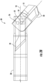
- connection system 22 connecting the inner shaft 24 to the blade 12 may include a pin 52 and a slot 54 that allow conversion of linear movement of the inner shaft 24 into rotational movement of the blade 12 to rotate the blade 12 to the second, flip position 20 upon linear movement of the inner shaft 24 in relation to the outer tube 28.
- the pin 52 may slide in the slot 54 to permit rotation of the blade 12 about the pivot point 56, which may be a pin or other appropriate device.
- the pivot point 56 is a point at which the blade 12 is pivotably coupled to the outer tube 28.
- the blade 12 may partially reside within a distal end of the outer tube 28 and may include two slots 57 configured to enable the blade 12 to be rotated into the second position 20.
- Such configuration enables the blade to be movable from the first position 16 to the second position 20, and vice versa, via lateral movement of the inner shaft 24.
- the blade 12 may be articulated to a nonparallel second position 20 relative to the longitudinal axis 18 of the elongated body 36 in which the cutting arris 50 of the blade 12 is exposed toward the proximal end 38 of the elongated body 36 for retrograde drilling of a hole 30 when the blade 12 is locked in the second, flip position 20.
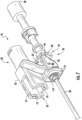
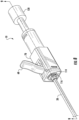
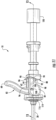
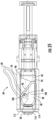
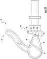
- the blade position control system 26 may include one or more cams 58 in communication with a cam follower 60 that is in communication with the inner shaft 24 for moving the blade 12 into first and second positions 16, 20.
- the cam 58 may be formed from a first head member 62 and a second head member 64 separated by a tube receiving chamber 66 configured to receive the inner shaft 24 extending therethrough.
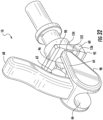
- an actuation device 68 which may be, but is not limited to being a lever arm, extending from the cam 58.
- the blade position control system 26 may include a housing 70 configured to retain the cam 58 in position whereby the housing 70 may include an inner side surface 72 that houses the cam 58 to prevent the cam 58 from being inadvertently displaced and to limit rotation of the cam 58 to rotate about only one axis.
- the housing 70 may include a first inner side surface 74 and a second inner side surface 76 that face each other and partially define a cam receiving cavity 78 configured such that the housing 70 limits movement of the cam 58 such that the cam 58 can only move with outer side surfaces 80 of the cam 58 moving in a direction generally aligned with first and second inner side surfaces 74, 76 of the housing 70.
- the housing 70 limits movement of the cam 58 between a first position 82, as shown in Figure 7 , with the actuation device 68 extending radially away from the housing 70 and a second position 84, as shown in Figures 25 and 26 , in which the actuation device 68 may be generally aligned with the outer tube 28.
- the cam 58 may also be configured to prevent over rotation of the cam 58.
- the cam 58 may include a first side edge 96 that is configured to prevent over rotation of the cam 58.
- the first side edge 96 of the cam 58 may be generally aligned with an inner surface 71 of the housing 70 when the cam 58 is in the first position 82.
- the cam 58 may include a second side edge 98 that is configured to prevent over rotation of the cam 58.
- the second side edge 98 of the cam 58 may be generally aligned with an inner surface 73 of the housing 70 when the cam 58 is in the second position 84.
- the cam follower 60 may include a first position retainer 86, as shown in Figures 30-33 , configured to retain the cam 58 in the first position 82, which also retains the blade 12 in a position generally aligned with the longitudinal axis 18, and a second position retainer 88 configured to retain the cam 58 in the second position 84 in which the cutting arris 50 of the blade 12 is positioned such that the cutting arris 50 is exposed toward the proximal end 38 of the elongated body 36 for retrograde drilling of a hole 30 while allowing the inner shaft 24 and blade 12 to rotate.
- the first position retainer 86 may be formed from a nonlinear engaging surface 94 with a flat surface 90 generally orthogonal to the longitudinal axis 18 of the elongated body 36, which also retains the blade 12 in a position generally aligned with the longitudinal axis 18.
- the second position retainer 90 may be formed from a flat surface 92 generally orthogonal to the longitudinal axis 18 of the elongated body 36.
- the second position retainer may be positioned closer to the distal end 14 of the elongated body 36 than the first position retainer 86.
- the engaging surface 94 of the cam follower 60 between the first and second position retainers 86, 88 is nonorthogonal relative to the longitudinal axis 18 of the elongated body 36.
- the device 10 may include at least one additional position for the blade 12 between the first and second positions 16, 20, as shown in Figures 30-36 .
- the blade 12 may be retained in a desired position somewhere between being aligned with the longitudinal axis 18, as shown in Figure 18 , and generally orthogonal to the longitudinal axis 18, as shown in Figure 20 .
- the device 10 may be configured such that the blade 12 may be retained in a third position 21, as shown in Figures 19 and 21 .
- the third position 21 may be in any desired position. In at least one embodiment, the third position 21 may be about halfway between the first and second positions 16, 20, as shown in Figures 30-33 .
- the third position may be positioned at about 45 degrees relative to the longitudinal axis 18.
- the blade 12 may be retained in the third position 21 via a third position retainer 121, as shown in Figure 29 , positioned between the first and second position retainers 86, 88 for retaining the cam 58 in a third position in which the blade 12 is positioned between the first and second positions.
- the third position retainer 121 may be, but is not limited to being, a flat surface 122 on the cam follower 60 that is positioned about midway between the flat surface 90, which corresponds to the first position 16 of the blade 12, and the flat surface 92, which corresponds to the second position 20 of the blade 12.
- the third position 21 enables a user of the device 10, such as a surgeon, to create compound sockets, counterbores and countersinks within bone.
- the device 10 may include additional positions for the blade 12 between the first and third positions 16, 21 and between the second and third positions 20, 21, as shown in Figures 30-36 .
- the cam 58 may be retained in a fourth position, as shown in Figures 32 and 33 , between the first and third positions via a fourth position retainer 123 positioned between the first and third position retainers 88, 121.
- the fourth position retainer 123 may be, but is not limited to being, a flat surface 124 on the cam follower 60 that is positioned between the flat surface 90, which corresponds to the first position 16 of the blade 12, and the flat surface 121, which corresponds to the third position 21 of the blade 12.
- the fourth position retainer 123 may be positioned at any point between the first and third position retainers 86, 121. In at least one embodiment, the fourth position retainer 123 may be positioned between the first position retainer 86 and the second position retainer 88, which corresponds to a fourth blade position 23 of between about 10 degrees and 40 degrees and, in at least one embodiment, 30 degrees, as shown in Figure 34 .
- the cam 58 may be retained in a fifth position, as shown in Figure 35 , between the second and third positions via a fifth position retainer 125 positioned between the second and third position retainers 88, 121.
- the fifth position retainer 125 may be, but is not limited to being, a flat surface 126 on the cam follower 60 that is positioned between the flat surface 92, which corresponds to the second position 20 of the blade 12, and the flat surface 121, which corresponds to the third position 21 of the blade 12.
- the fifth position retainer 125 may be positioned at any point between the second and third position retainers 88, 121.
- the fifth position retainer 125 may be positioned between the second position retainer 88 and the third position retainer 121, which corresponds to a fifth blade position of between about 50 degrees and 80 degrees and, in at least one embodiment, 60 degrees, as shown in Figure 36 .
- a user such as, but not limited to, a surgeon, may cut bone with the blade 12 in any of the positions previously described.
- the user may create a counterbore by first cutting bone with the blade 12.
- the user may then move the blade 12 into a position in which the blade 12 is more closely aligned with the first position 16 and the longitudinal axis 18.
- the remaining hole may be created with the blade 12 more closely aligned with the first position 16 and the longitudinal axis 18.
- the user may adjust the axial movement of the inner shaft 24 by controlling the position of the cam 58 in contact with the cam follower 60 to produce holes with varying degrees of counter sink at the bottom of the hole.
- the user may also vary the position of the blade 12 to create holes with varying diameter by axially moving the inner shaft 24, thereby controlling the position of the cam 58 in contact with the cam follower 60 to create holes with varying diameters.
- a 5 mm blade may produce 10 mm hole when flipped at 90 degrees in the second position 20.
- the same 5 mm blade flipped at 30 degrees (corresponding to flat surface 124 on the cam follower 60) or flipped at 45 degrees (corresponding to flat surface 122 on the cam follower 60) could produce holes less than 10 mm in diameter.
- the position of the cam 58 may be changed relative to the cam follower 60 via the lever arm 68.
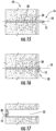
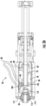
- the blade position control system 26 may include a position retention system 34 configured to retain the cam 58 in a second position 84 such that the inner shaft 24 is retained in the second position 20, thereby retaining the cutting arris 50 of the blade 12 in position such that the cutting arris 50 is exposed toward the proximal end 38 of the elongated body 36 for retrograde drilling of a hole 30 while allowing the inner shaft 24 and blade 12 to rotate.
- the position retention system 34 may include one or more pins 100 extending from the cam 58.
- the position retention system 34 may include one or more grooves 102 on the inner shaft 24 for receiving the pin 100 extending from the cam 58 such that the inner shaft 24 is rotatable while the pin 100 resides in the groove 102 on the inner shaft 24, thereby preventing axial movement of the inner shaft 24.
- the position retention system 34 may include one or more slots 104 in the cam 58 for receiving the pin 100 to account for potential misalignment between the pin 100, cam 58 and the groove 102 on the inner shaft 24.
- the inner and outer tubes 24, 28 may rotate together.
- the outer tube 28 may support the inner shaft 24.
- the inner and outer tubes 24, 28 may be coupled together in any appropriate manner that enables the inner shaft 24 or outer tube 28 to move relative to the other.
- the inner shaft 24 may be coupled to the outer tube 28 via a pin 110 attached to the outer tube 28 and extending radially inward into a slot 112 positioned in the inner shaft 24.
- the slot 112 in the outer tube 28, as shown in Figure 9 enables the inner shaft 24 to move axially relative to the outer tube 28.
- the device 10 may include a flange 114 attached to the outer tube 28 to reduce friction between outer tube 28 and housing 70 to enable the outer tube 28 to rotate.
- the device 10 may include a flange 114 attached to the outer tube 28 to reduce friction between outer tube 28 and a bushing 116 fitted within a cap 117 at a distal end of the housing 70 to enable the outer tube 28 to rotate.
- the flange 114 may support a bushing 116 attached to a cap 117, as shown in Figures 9-12 , configured to be attached to a distal end of the housing 70.
- the bushing 116 enables the outer tube 28 to rotate without melting the cap 117.
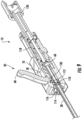
- the device 10 may also include a biasing mechanism 118, as shown in Figure 2 , configured to bias the cam follower 60 towards the cam 58 to keep the cam follower 60 in contact with the cam 58 and configured to bias the inner shaft 24 toward the distal end 14 of the elongated body 36.
- the biasing mechanism 118 may bias the cam follower 60 toward the distal end 14 and into contact with the cam 58.
- the biasing mechanism 118 may be configured to be a compression spring.
- the device 10 may also include a drive hub 120 positioned at the proximal end 38.
- the drive hub 120 may be configured to place the inner shaft 24 in mechanical communication with a handpiece to impart rotary motion to the inner shaft 24 and blade 12, and, in at least one embodiment, the outer tube 28, as controlled by controls on the handpiece of the device 10.
- the drive hub 120 may be detachable from the handpiece, thereby enabling other instruments to be attached to and driven by the same handpiece.
- a method 130 of retrograde drilling of sockets for ACL reconstruction surgery using the device 10 may include preparing a surgical site within a patient by providing access to a bone surface at step 132.
- the method 130 may include at step 134 placing the blade 12 into the first position 16 aligned with a longitudinal axis 18 of the device 10.
- the method 130 may include at step 136 activating the device 10 such that the blade 12 rotates.
- the blade 12 may rotate with sufficient revolutions per minute (rpm) to drill into the bone.
- the method 130 may include at step 138 drilling the hole 30 into the bone in a patient.
- the method 130 may include at step 140 actuating the actuation device 68 to move the cam 58 from the first position 82 to the second position 84, which causes the blade 12 to be moved from the first position 16 aligned with a longitudinal axis 18 of the device 10 to the second position 20 nonparallel to the longitudinal axis 18 to create a retrograde socket 32 or tunnel.
- the method 130 may include at step 142 activating the device 10 such that the blade 12 rotates.
- the method 130 may include at step 144 may include withdrawing the blade 12 so that the blade 12 contacts the bone and creates a retrograde socket 32 or tunnel. The blade should be withdrawn less than a full length of the hole 30 in the bone.
- the method 130 may include at step 146 actuating the actuation device 68 to move the cam 58 from the second position 84 to the first position 82, which causes the blade 12 to be moved from the second position 20 nonparallel to the longitudinal axis 18 to the first position 16 aligned with a longitudinal axis 18 of the device 10.
- the method 130 may include at step 148 withdrawing the blade 12 from the patient.
- the step 140 for actuating the actuation device 68 may include actuating the device to move the blade 12 such that the blade 12 is positioned in a third position 21 between the first position 16, which may be at 0 degrees, and the second position 20, which may be at 90 degrees.
- the step 140 for actuating the actuation device 68 may include actuating the device to move the blade 12 such that the blade 12 is positioned in a position between the first position 16, which may be at 0 degrees, and the third position 21, which may be at 45 degrees.
- the step 140 for actuating the actuation device 68 may include actuating the device to move the blade 12 such that the blade 12 is positioned in a position between the second position 20, which may be at 90 degrees, and the third position 21, which may be at 45 degrees.
- the method 130 may also include creating compound sockets, counterbores and countersinks within bone.
- the method 130 may include creating a hole as previously set forth.
- the blade 12, when not in contact with the bone, may be moved into a position in which the blade is closer to the 90 degree flipped position 20 than the 0 degree starting position 16.
- the blade 12 may then be moved into contact with the bone by partially withdrawing the inner shaft 24 and outer tube 28 from the hole.
- the blade 12 may create a socket when the inner shaft 24 and blade 12 are rotated together as the inner shaft 24 and outer tube 28 from the hole are partially withdrawn from the hole.
- the outer tube 28 may rotate together with the inner shaft 24 and the blade 12.
- the blade 12 may be returned to the first position 16 to withdraw the blade 12 from the hole. This same procedure may be undertaken to create hole with varying degrees of counter sink at the bottom of the hole. The position of the blade 12 may be changed multiple times to create varying degrees of counter sink at the bottom of the hole.
Landscapes
- Health & Medical Sciences (AREA)
- Surgery (AREA)
- Life Sciences & Earth Sciences (AREA)
- Biomedical Technology (AREA)
- Medical Informatics (AREA)
- Orthopedic Medicine & Surgery (AREA)
- Oral & Maxillofacial Surgery (AREA)
- Engineering & Computer Science (AREA)
- Dentistry (AREA)
- Heart & Thoracic Surgery (AREA)
- Nuclear Medicine, Radiotherapy & Molecular Imaging (AREA)
- Molecular Biology (AREA)
- Animal Behavior & Ethology (AREA)
- General Health & Medical Sciences (AREA)
- Public Health (AREA)
- Veterinary Medicine (AREA)
- Surgical Instruments (AREA)
Claims (16)
- Drehschneideinrichtung (10), die aufweist:einen langgestreckten Körper (36) mit einem distalen Ende (14), einem proximalen Ende (38) und einer Längsachse (18), wobei der langgestreckte Körper (36) weiterhin ein Außenrohr (28) und einen innere Welle (24), die durch das Außenrohr aufgenommen wird, aufweist,eine Klinge (12) am distalen Ende (14) des Körpers (36), wobei die Klinge (12) dazu ausgebildet ist, sich von einer ersten Position (16), die im Allgemeinen mit der Längsachse (18) ausgerichtet ist, in eine zweite, umgedrehte Position (20), die nicht parallel zu der Längsachse (18) ist, zu drehen; undein Klingenpositions-Steuerungssystem (26), das die Klinge (12) mit distalen Enden sowohl des Außenrohrs (28) als auch der inneren Welle (24) verbindet, wobei das Klingenpositions-Steuerungssystem (26) aufweist:ein die innere Welle (24) mit der Klinge (12) verbindendes Verbindungssystem (22), das es der Klinge (12) ermöglicht, sich aus der ersten Position (16), die im Allgemeinen mit der Längsachse (18) ausgerichtet ist, in die zweite, umgedrehte Position (20) zu bewegen, die nicht parallel zu der Längsachse (18) ist und in der eine Schneidkante(50) der Klinge (12) in Richtung des proximalen (38) Endes des länglichen Körpers (36) zum retrograden Bohren eines Lochs freiliegt, wenn die Klinge (12) in der zweiten, umgedrehten Position (20) arretiert ist;einen Nocken (58), der mit einem Nockenstößel (60) kommuniziert und mit der inneren Welle (24) kommuniziert, um die Klinge (12) in die erste und zweite Position (16, 20) zu bewegen; undein Positionshaltesystem (34), das dazu ausgebildet ist, den Nocken (58) in einer zweiten Position zu halten, so dass die der innere Welle (24) in der zweiten Position gehalten wird und dabei die Schneidkante (50) der Klinge (12) in Position zu halten, so dass die Schneidkante (50) in Richtung des proximalen Endes (36) des länglichen Körpers (38) zum retrograden Bohren eines Lochs freiliegt, während es der der inneren Welle und der Klinge ermöglicht wird, sich zu drehen; dadurch gekennzeichnet, dass der Nockenstößel (60) enthälteinen ersten Positionshalter (86), der dazu ausgebildet ist, den Nocken (58) in einer ersten Position (82) zu halten, die auch die Klinge (12) in der ersten Position (16) hält, die im Allgemeinen mit der Längsachse (18) ausgerichtet ist, und einen zweiten Positionshalter (88), der dazu ausgebildet ist, den Nocken (58) in einer zweiten Position (84) zu halten, in der die Schneidkante (50) der Klinge (12) so positioniert ist, dass die Schneidkante (50) in Richtung des proximalen Endes (38) des länglichen Körpers (36) freiliegt, während es der inneren Welle (24) und der Klinge (12) ermöglich wird, sich zum retrograden Bohren eines Lochs zu drehen.
- Drehschneideinrichtung (10) nach Anspruch 1, wobei das Positionshaltesystem (34) zumindest einen Stift (100), der sich von dem Nocken (58) weg erstreckt, enthält.
- Drehschneideinrichtung (10) nach Anspruch 2, wobei das Positionshaltesystem (34) zumindest eine Nut (102) auf der inneren Welle (24) zum Aufnehmen des zumindest einen Stifts (100), der sich von dem Nocken (58) weg erstreckt, enthält, so dass die innere Welle (24) drehbar ist, während der zumindest eine Stift (100) in der zumindest einen Nut (102) auf der der inneren Welle (24) sitzt, wodurch eine axiale Bewegung der inneren Welle (24) verhindert wird.
- Drehschneideinrichtung (10) nach Anspruch 3, wobei das Positionshaltesystem (34) zumindest einen Schlitz (104) in dem Nocken (58) zum Aufnehmen des zumindest einen Stifts (100) enthält, um eine mögliche Fehlausrichtung zwischen dem Stift (100), der Nocke (58) und zumindest einer Nut (102) auf der inneren Welle (24) zu berücksichtigen.
- Drehschneideinrichtung (10) nach Anspruch 1, wobei der Nocken (58) aus einem ersten Kopfelement (62) und einem zweiten Kopfelement (64) gebildet ist, die durch eine Rohraufnahmekammer (66) getrennt sind, die dazu ausgebildet ist, die sich durch sie erstreckende innere Welle (24) aufzunehmen.
- Drehschneideinrichtung (10) nach Anspruch 1, wobei der erste Positionshalter (86) aus einer flachen Oberfläche (90) auf dem Nockenstößel (60) gebildet ist, wobei die flache Oberfläche (90) im Allgemeinen senkrecht zu der Längsachse (18) des länglichen Körpers (36) ist, der auch die Klinge (12) in einer Position hält, die im Allgemeinen mit der Längsachse (18) ausgerichtet ist.
- Drehschneideinrichtung (10) nach Anspruch 6, wobei die Eingreifoberfläche des Nockenstößels (60) zwischen dem ersten und zweiten Positionshalter (86, 88) relativ zu der Längsachse des länglichen Körpers (36) nicht senkrecht ist.
- Drehschneideinrichtung (10) nach Anspruch 1, wobei der zweite Positionshalter (88) aus einer flachen Oberfläche (92) auf dem Nockenstößel (60) gebildet ist, wobei die flache Oberfläche (92) im Allgemeinen senkrecht zu der Längsachse (18) des länglichen Körpers (36) ist.
- Drehschneideinrichtung (10) nach Anspruch 1, wobei der zweite Positionshalter (88) näher als der erste Positionshalter (86) am distalen Ende (14) des länglichen Körpers (36) positioniert ist.
- Drehschneideinrichtung (10) nach Anspruch 1, die weiterhin einen dritten Positionshalter (121), der zwischen dem ersten und zweiten Halter (86, 88) angeordnet ist, aufweist, um den Nocken (58) in einer dritten Position (21), in der die Klinge (12) zwischen der ersten und der zweiten Position (16, 20) positioniert ist, zu halten.
- Drehschneideinrichtung (10) nach Anspruch 1, die weiterhin einen vierten Positionshalter (123), der zwischen dem ersten und dritten Halter (86, 121) positioniert ist, aufweist, um den Nocken (58) in einer vierten Position, die einer Klingenposition zwischen 10 Grad und 40 Grad relativ zu der Längsachse (18) entspricht, zu halten.
- Drehschneideinrichtung (10) nach Anspruch 1, die weiterhin einen fünften Positionshalter (125), der zwischen dem zweiten und dritten Halter (88, 121) positioniert ist, aufweist, um den Nocken (58) in einer fünften Position, die einer Klingenposition zwischen 50 Grad und 80 Grad relativ zu der Längsachse (18) entspricht, zu halten.
- Drehschneideinrichtung (10) nach Anspruch 1, die weiterhin ein Gehäuse (70) aufweist, das dazu ausgebildet ist, den Nocken (58) in Position zu halten, wobei das Gehäuse (70) eine innere seitliche Oberfläche (72) enthält, die den Nocken (58) aufnimmt, um zu verhindern, dass der Nocken (58) versehentlich verschoben wird, und um die Drehung des Nockens (58) um nur eine Achse zu begrenzen.
- Drehschneideinrichtung (10) nach Anspruch 1, die weiterhin einen Vorspannmechanismus (118) aufweist, der dazu ausgebildet ist, den Nockenstößel (60) in Richtung des Nockens (58) vorzuspannen, um den Nockenstößel (60) in Kontakt mit dem Nocken (58) zu halten, und der dazu ausgebildet ist, die innere Welle (24) in Richtung des distalen Endes (14) des langgestreckten Körpers (36) vorzuspannen.
- Drehschneideinrichtung (10) nach Anspruch 1, die weiterhin eine Antriebsnabe (120), die an dem proximalen Ende (38) angeordnet ist, aufweist, wobei die Antriebsnabe (120) dazu ausgebildet ist, die innere Welle (24) in mechanischer Kommunikation mit einem Handstück zu bringen, um der inneren Welle (24) und der Klinge (12) eine Drehbewegung zu verleihen, die durch Bedienelemente an dem Handstück gesteuert wird.
- Drehschneideinrichtung (10) nach Anspruch 1, wobei das Verbindungssystem (22), das die der innere Welle (24) mit der Klinge (12) verbindet, einen Stift (52) und einen Schlitz (54) aufweist, die eine Umwandlung einer linearen Bewegung der inneren Welle (24) in eine Drehbewegung der Klinge (12) ermöglichen, um die Klinge (12) bei einer linearen Bewegung der inneren Welle (24) im Verhältnis zu dem Außenrohr (28) in die zweite, umgedrehte Position (20) zu drehen, wobei der Stift (52) in dem Schlitz (54) gleitet, um eine Drehung der Klinge (12) zu ermöglichen, und wobei die Klinge relativ zu der Längsachse (18) des länglichen Körpers (36) in eine nicht-parallele Position gelenkt ist, wenn sich die Klinge (12) in der zweiten, umgedrehten Position (20) befindet, und wobei die Schneidkante (50) der Klinge (12) in Richtung des proximalen Endes (38) des länglichen Körpers (36) zum retrograden Bohren eines Lochs freiliegt, wenn die Klinge (12) in der zweiten, umgedrehten Position (20) verriegelt ist.
Applications Claiming Priority (2)
| Application Number | Priority Date | Filing Date | Title |
|---|---|---|---|
| US15/683,434 US10695073B2 (en) | 2017-08-22 | 2017-08-22 | Control system for retrograde drill medical device |
| PCT/US2018/021994 WO2019040121A1 (en) | 2017-08-22 | 2018-03-12 | CONTROL SYSTEM FOR RETROGRADE DRILLING MEDICAL DEVICE |
Publications (4)
| Publication Number | Publication Date |
|---|---|
| EP3672504A1 EP3672504A1 (de) | 2020-07-01 |
| EP3672504A4 EP3672504A4 (de) | 2021-05-05 |
| EP3672504B1 true EP3672504B1 (de) | 2024-10-23 |
| EP3672504C0 EP3672504C0 (de) | 2024-10-23 |
Family
ID=65436508
Family Applications (1)
| Application Number | Title | Priority Date | Filing Date |
|---|---|---|---|
| EP18848385.3A Active EP3672504B1 (de) | 2017-08-22 | 2018-03-12 | Steuersystem für eine medizinische retrograde bohrvorrichtung |
Country Status (6)
| Country | Link |
|---|---|
| US (1) | US10695073B2 (de) |
| EP (1) | EP3672504B1 (de) |
| JP (1) | JP7019797B2 (de) |
| KR (1) | KR102555089B1 (de) |
| CN (1) | CN110996817B (de) |
| WO (1) | WO2019040121A1 (de) |
Families Citing this family (27)
| Publication number | Priority date | Publication date | Assignee | Title |
|---|---|---|---|---|
| US8388624B2 (en) | 2003-02-24 | 2013-03-05 | Arthrosurface Incorporated | Trochlear resurfacing system and method |
| CA2686814A1 (en) | 2006-12-11 | 2008-06-19 | Arthrosurface Incorporated | Retrograde resection apparatus and method |
| US9662126B2 (en) | 2009-04-17 | 2017-05-30 | Arthrosurface Incorporated | Glenoid resurfacing system and method |
| US10945743B2 (en) | 2009-04-17 | 2021-03-16 | Arthrosurface Incorporated | Glenoid repair system and methods of use thereof |
| CA2792048A1 (en) | 2010-03-05 | 2011-09-09 | Arthrosurface Incorporated | Tibial resurfacing system and method |
| US20130165982A1 (en) | 2011-12-22 | 2013-06-27 | Arthrosurface Incorporated | System and Method for Bone Fixation |
| DE112013003358T5 (de) | 2012-07-03 | 2015-03-19 | Arthrosurface, Inc. | System und Verfahren für Gelenkoberflächenersatz und -reparatur |
| US9492200B2 (en) | 2013-04-16 | 2016-11-15 | Arthrosurface Incorporated | Suture system and method |
| US9861492B2 (en) | 2014-03-07 | 2018-01-09 | Arthrosurface Incorporated | Anchor for an implant assembly |
| US10624748B2 (en) | 2014-03-07 | 2020-04-21 | Arthrosurface Incorporated | System and method for repairing articular surfaces |
| US11607319B2 (en) | 2014-03-07 | 2023-03-21 | Arthrosurface Incorporated | System and method for repairing articular surfaces |
| CN107106186B (zh) | 2014-10-19 | 2020-01-21 | Tag医疗器材农业合作有限公司 | 包含引导系统与骨骼材料移除装置的套件 |
| CN107530091B (zh) | 2015-04-09 | 2021-08-03 | Tag医疗器材农业合作有限公司 | 骨头材料移除的装置及其使用方法 |
| DE102015111877A1 (de) * | 2015-07-22 | 2017-01-26 | Aesculap Ag | Werkzeugaufnahmeaufsatz für chirurgische Bohrmaschine mit zusätzlicher manueller Antriebseinheit und chirurgische Bohrmaschine |
| DE102015111878A1 (de) | 2015-07-22 | 2017-01-26 | Aesculap Ag | Platzsparende Ratscheinheit mit Freilauf |
| EP3413810B1 (de) | 2016-02-11 | 2021-08-18 | T.A.G. Medical Devices - Agriculture Cooperative Ltd. | Vorrichtung zur entfernung von knochenmaterial |
| EP4371510B1 (de) | 2016-04-24 | 2026-02-18 | T.A.G. Medical Products Corporation Ltd. | Führungsvorrichtung |
| US11207080B2 (en) * | 2017-06-12 | 2021-12-28 | Conmed Corporation | Orthopedic drill bit with swiveling head |
| WO2019028344A1 (en) | 2017-08-04 | 2019-02-07 | Arthrosurface Incorporated | JOINT SURFACE IMPLANT WITH MULTIPLE COMPONENTS |
| US11510686B2 (en) * | 2018-07-05 | 2022-11-29 | Conmed Corporation | Retrograde drilling device |
| CN112672670B (zh) | 2018-08-01 | 2024-08-30 | Tag医疗器材农业合作有限公司 | 可调整钻孔装置及其使用方法 |
| US11478358B2 (en) | 2019-03-12 | 2022-10-25 | Arthrosurface Incorporated | Humeral and glenoid articular surface implant systems and methods |
| US11819233B2 (en) * | 2020-01-24 | 2023-11-21 | Medtronic Xomed, Inc. | Devices and techniques for separating tissue |
| EP4059449A1 (de) * | 2021-03-15 | 2022-09-21 | Fundación Tecnalia Research & Innovation | Expansionsbohrer und verfahren zum bohren eines lochs unter verwendung dieses expansionsbohrers |
| CA3239760A1 (en) | 2021-12-17 | 2023-06-22 | Joint Preservation Innovations, LLC | Articulating rotary cutting tool |
| JP7260118B1 (ja) * | 2021-12-22 | 2023-04-18 | 学校法人東京女子医科大学 | ドリルストッパ |
| CN114587515B (zh) * | 2022-03-15 | 2024-05-07 | 青岛智兴医疗器械有限公司 | 一种可360°转动并可调整刀头角度的可旋转铰刀 |
Family Cites Families (62)
| Publication number | Priority date | Publication date | Assignee | Title |
|---|---|---|---|---|
| US4963147A (en) | 1987-09-18 | 1990-10-16 | John M. Agee | Surgical instrument |
| US5620456A (en) | 1995-10-20 | 1997-04-15 | Lasersurge, Inc. | Trocar assembly |
| US6332880B1 (en) | 1996-12-19 | 2001-12-25 | Ep Technologies, Inc. | Loop structures for supporting multiple electrode elements |
| US5913867A (en) | 1996-12-23 | 1999-06-22 | Smith & Nephew, Inc. | Surgical instrument |
| US6048346A (en) | 1997-08-13 | 2000-04-11 | Kyphon Inc. | Systems and methods for injecting flowable materials into bones |
| US6033411A (en) | 1997-10-14 | 2000-03-07 | Parallax Medical Inc. | Precision depth guided instruments for use in vertebroplasty |
| US6053907A (en) | 1998-08-13 | 2000-04-25 | Endius Incorporated | Surgical instruments with flexible drive shaft |
| US6464711B1 (en) | 1999-03-19 | 2002-10-15 | Medtronic Xomed, Inc. | Articulating mechanism for steerable surgical cutting instruments |
| US6358251B1 (en) | 2000-03-21 | 2002-03-19 | University Of Washington | Method and apparatus for forming a cavity in soft tissue or bone |
| US6610067B2 (en) | 2000-05-01 | 2003-08-26 | Arthrosurface, Incorporated | System and method for joint resurface repair |
| EP2314257B9 (de) | 2000-05-01 | 2013-02-27 | ArthroSurface, Inc. | System zur Gelenkoberflächenerneuerung |
| US8057477B2 (en) | 2000-06-24 | 2011-11-15 | Greatbatch Medical S.A. | Guided reamer system for reshaping bone |
| US6669698B1 (en) | 2000-10-24 | 2003-12-30 | Sdgi Holdings, Inc. | Vertebrae fastener placement guide |
| US6916306B1 (en) | 2000-11-10 | 2005-07-12 | Boston Scientific Scimed, Inc. | Steerable loop structures for supporting diagnostic and therapeutic elements in contact with body tissue |
| US6610058B2 (en) | 2001-05-02 | 2003-08-26 | Cardiac Pacemakers, Inc. | Dual-profile steerable catheter |
| US6478801B1 (en) | 2001-07-16 | 2002-11-12 | Third Millennium Engineering, Llc | Insertion tool for use with tapered trial intervertebral distraction spacers |
| US7828804B2 (en) | 2002-11-08 | 2010-11-09 | Warsaw Orthopedic, Inc. | Transpedicular intervertebral disk access methods and devices |
| US7238189B2 (en) * | 2003-03-18 | 2007-07-03 | Arthrex, Inc. | ACL reconstruction technique using retrodrill |
| JP4555293B2 (ja) | 2003-09-03 | 2010-09-29 | カイフォン・ソシエテ・ア・レスポンサビリテ・リミテ | 内部身体領域に空洞を生成するためのデバイスおよび関連する方法 |
| EP1514518A1 (de) | 2003-09-11 | 2005-03-16 | SDGI Holdings, Inc. | Schlagartig angetriebene Werkzeuge zur Vorbereitung der Wirbelendflächen |
| WO2006074321A2 (en) | 2003-11-20 | 2006-07-13 | Arthrosurface, Inc. | System and method for retrograde procedure |
| US8603106B2 (en) | 2005-05-20 | 2013-12-10 | Neotract, Inc. | Integrated handle assembly for anchor delivery system |
| US8080061B2 (en) | 2005-06-20 | 2011-12-20 | Synthes Usa, Llc | Apparatus and methods for treating bone |
| US8021365B2 (en) | 2005-07-11 | 2011-09-20 | Kyphon Sarl | Surgical device having interchangeable components and methods of use |
| US7442195B1 (en) | 2005-09-12 | 2008-10-28 | Behrens Alfred F | Apparatus and method for the reduction of bone fractures |
| US8016846B2 (en) | 2005-10-27 | 2011-09-13 | Medtronic Xomed, Inc. | Micro-resecting and evoked potential monitoring system and method |
| US8480673B2 (en) | 2006-06-01 | 2013-07-09 | Osteo Innovations Llc | Cavity creation device and methods of use |
| US8465491B2 (en) | 2006-06-01 | 2013-06-18 | Osteo Innovations Llc | Bone drill |
| US7780690B2 (en) | 2006-06-08 | 2010-08-24 | Recon Surgical, Inc. | Instruments and method for minimally invasive carpal tunnel release |
| US7666200B2 (en) | 2006-07-19 | 2010-02-23 | Target Medical Innovations Llc | Endoscopic cutting instrument with axial and rotary motion |
| CA2686814A1 (en) | 2006-12-11 | 2008-06-19 | Arthrosurface Incorporated | Retrograde resection apparatus and method |
| WO2008076330A1 (en) * | 2006-12-15 | 2008-06-26 | Soteira, Inc. | Drills and methods for vertebrostenting |
| US9480485B2 (en) | 2006-12-15 | 2016-11-01 | Globus Medical, Inc. | Devices and methods for vertebrostenting |
| GB0702948D0 (en) | 2007-02-15 | 2007-03-28 | Depuy Int Ltd | A tool for forming a cavity within a bone |
| US8652139B2 (en) | 2007-05-02 | 2014-02-18 | Arthrex, Inc. | Flip retrograde cutting instrument |
| US8591514B2 (en) | 2007-05-02 | 2013-11-26 | Arthrex, Inc. | Retrograde cutter with rotating blade |
| US8012170B2 (en) * | 2009-04-27 | 2011-09-06 | Tyco Healthcare Group Lp | Device and method for controlling compression of tissue |
| US20090131886A1 (en) | 2007-11-16 | 2009-05-21 | Liu Y King | Steerable vertebroplasty system |
| EP2098177B1 (de) | 2008-03-03 | 2013-10-16 | Arthrex, Inc. | Kombinierter Kippfräser und -bohrer |
| EP2502595B1 (de) | 2008-05-05 | 2014-10-01 | Stryker Corporation | Steuerungskonsole für ein chirurgisches Werkzeug, wobei die Konsole zum Ablesen von Daten aus einem integrierten Speicher mit dem Werkzeug von den Konsolenklemmen in der Lage ist, über die das Werkzeug mit Strom versorgt wird |
| US8394101B2 (en) | 2009-02-23 | 2013-03-12 | Globus Medical, Inc. | Discectomy instrument |
| US8852201B2 (en) | 2009-03-30 | 2014-10-07 | Arthrex, Inc. | Microfracture instrument |
| US8449552B2 (en) | 2009-06-04 | 2013-05-28 | Quantum Surgical | Surgical drill guide with awl and method of use |
| AU2010212441B2 (en) | 2009-08-20 | 2013-08-01 | Howmedica Osteonics Corp. | Flexible ACL instrumentation, kit and method |
| US8480682B2 (en) | 2009-08-28 | 2013-07-09 | Zimmer Dental, Inc. | Device for limiting the drilling depth of a drill |
| US8348950B2 (en) | 2010-01-04 | 2013-01-08 | Zyga Technology, Inc. | Sacroiliac fusion system |
| US9161763B2 (en) | 2010-01-04 | 2015-10-20 | Zyga Technology, Inc. | Sacroiliac fusion system |
| US8535311B2 (en) | 2010-04-22 | 2013-09-17 | Ethicon Endo-Surgery, Inc. | Electrosurgical instrument comprising closing and firing systems |
| EP2977013B1 (de) * | 2010-06-29 | 2019-08-07 | Synthes GmbH | Einsatzinstrument für eine ankeranordnung |
| US8801713B2 (en) | 2011-04-07 | 2014-08-12 | DePuy Synthes Products, LLC | Surgical drill instrument with motor and locking mechanism to receive an attachment and a cutting burr |
| BR112013029079A2 (pt) | 2011-05-12 | 2017-02-07 | Nlt Spine Ltd | dispositivo de rompimento do tecido e métodos correspondentes |
| WO2013003730A1 (en) | 2011-06-30 | 2013-01-03 | Depuy Products, Inc. | Patella clamp and drill guide surgical instrument |
| US9119639B2 (en) | 2011-08-09 | 2015-09-01 | DePuy Synthes Products, Inc. | Articulated cavity creator |
| DE102012008970B3 (de) | 2012-05-03 | 2013-06-27 | Joimax Gmbh | Chirurgische Werkzeugeinrichtung |
| US9439693B2 (en) | 2013-02-01 | 2016-09-13 | DePuy Synthes Products, Inc. | Steerable needle assembly for use in vertebral body augmentation |
| MX2015011809A (es) * | 2013-03-12 | 2016-04-19 | Smith & Nephew Inc | Retroescariador de alambre guia. |
| US10470762B2 (en) * | 2013-03-14 | 2019-11-12 | Ethicon Llc | Multi-function motor for a surgical instrument |
| US9504478B2 (en) | 2014-04-30 | 2016-11-29 | Gyrus ACMI , Inc. | Rotary tool with improved coupling assembly |
| US9795395B2 (en) * | 2014-06-10 | 2017-10-24 | Medos International Sarl | Retro-cutting instrument with adjustable limit setting |
| GB2557479B (en) | 2015-08-05 | 2020-12-30 | Cummins Emission Solutions Inc | Oxygen correction for engine-out NOX estimates using a NOX sensor of an aftertreatment system |
| US20170137997A1 (en) * | 2015-11-17 | 2017-05-18 | Stowe Woodward Licensco, Llc | Polyurethane roll cover for calender roll for papermaking machine |
| EP3413810B1 (de) * | 2016-02-11 | 2021-08-18 | T.A.G. Medical Devices - Agriculture Cooperative Ltd. | Vorrichtung zur entfernung von knochenmaterial |
-
2017
- 2017-08-22 US US15/683,434 patent/US10695073B2/en active Active
-
2018
- 2018-03-12 KR KR1020207007957A patent/KR102555089B1/ko active Active
- 2018-03-12 WO PCT/US2018/021994 patent/WO2019040121A1/en not_active Ceased
- 2018-03-12 EP EP18848385.3A patent/EP3672504B1/de active Active
- 2018-03-12 CN CN201880053761.XA patent/CN110996817B/zh active Active
- 2018-03-12 JP JP2020510593A patent/JP7019797B2/ja active Active
Also Published As
| Publication number | Publication date |
|---|---|
| CN110996817B (zh) | 2023-05-26 |
| KR20200044043A (ko) | 2020-04-28 |
| EP3672504A4 (de) | 2021-05-05 |
| EP3672504A1 (de) | 2020-07-01 |
| KR102555089B1 (ko) | 2023-07-12 |
| US20190059910A1 (en) | 2019-02-28 |
| US10695073B2 (en) | 2020-06-30 |
| WO2019040121A1 (en) | 2019-02-28 |
| JP2020531136A (ja) | 2020-11-05 |
| JP7019797B2 (ja) | 2022-02-15 |
| EP3672504C0 (de) | 2024-10-23 |
| CN110996817A (zh) | 2020-04-10 |
Similar Documents
| Publication | Publication Date | Title |
|---|---|---|
| EP3672504B1 (de) | Steuersystem für eine medizinische retrograde bohrvorrichtung | |
| US12369927B2 (en) | Adjustable drilling device and a method for use thereof | |
| AU2008341062B2 (en) | Multiple portal guide | |
| US5797939A (en) | Endoscopic scissors with longitudinal operating channel | |
| US6685724B1 (en) | Laparoscopic surgical instrument and method | |
| EP3946089A1 (de) | Zange mit zweiteiliger antriebsstange | |
| US20040147909A1 (en) | Surgical instrument | |
| JP2004532061A (ja) | 経皮的外科手術用装置及び方法 | |
| GB2466180A (en) | Mechanisms for connecting a handle to a surgical instrument | |
| US10702285B2 (en) | Method and apparatus for performing minimally invasive arthroscopic procedures | |
| US20250049444A1 (en) | Incision Tools And Methods Of Use | |
| CA2512137C (en) | Surgical instrument with near-axial geometry | |
| US11751866B2 (en) | Endoscopic stitching device having angled suture needle | |
| CN116194052A (zh) | 关节运动的外科手术设备 | |
| WO2005060839A1 (en) | Reamer guide and method | |
| WO2001013804A1 (en) | Laparoscopic surgical instrument and method |
Legal Events
| Date | Code | Title | Description |
|---|---|---|---|
| STAA | Information on the status of an ep patent application or granted ep patent |
Free format text: STATUS: THE INTERNATIONAL PUBLICATION HAS BEEN MADE |
|
| PUAI | Public reference made under article 153(3) epc to a published international application that has entered the european phase |
Free format text: ORIGINAL CODE: 0009012 |
|
| STAA | Information on the status of an ep patent application or granted ep patent |
Free format text: STATUS: REQUEST FOR EXAMINATION WAS MADE |
|
| 17P | Request for examination filed |
Effective date: 20200211 |
|
| AK | Designated contracting states |
Kind code of ref document: A1 Designated state(s): AL AT BE BG CH CY CZ DE DK EE ES FI FR GB GR HR HU IE IS IT LI LT LU LV MC MK MT NL NO PL PT RO RS SE SI SK SM TR |
|
| AX | Request for extension of the european patent |
Extension state: BA ME |
|
| DAV | Request for validation of the european patent (deleted) | ||
| DAX | Request for extension of the european patent (deleted) | ||
| A4 | Supplementary search report drawn up and despatched |
Effective date: 20210409 |
|
| RIC1 | Information provided on ipc code assigned before grant |
Ipc: A61B 17/16 20060101AFI20210401BHEP |
|
| REG | Reference to a national code |
Ref country code: DE Ref legal event code: R079 Free format text: PREVIOUS MAIN CLASS: A61B0017320000 Ipc: A61B0017160000 Ref document number: 602018075818 Country of ref document: DE |
|
| GRAP | Despatch of communication of intention to grant a patent |
Free format text: ORIGINAL CODE: EPIDOSNIGR1 |
|
| STAA | Information on the status of an ep patent application or granted ep patent |
Free format text: STATUS: GRANT OF PATENT IS INTENDED |
|
| RIC1 | Information provided on ipc code assigned before grant |
Ipc: A61B 17/16 20060101AFI20240521BHEP |
|
| INTG | Intention to grant announced |
Effective date: 20240613 |
|
| GRAS | Grant fee paid |
Free format text: ORIGINAL CODE: EPIDOSNIGR3 |
|
| GRAA | (expected) grant |
Free format text: ORIGINAL CODE: 0009210 |
|
| STAA | Information on the status of an ep patent application or granted ep patent |
Free format text: STATUS: THE PATENT HAS BEEN GRANTED |
|
| AK | Designated contracting states |
Kind code of ref document: B1 Designated state(s): AL AT BE BG CH CY CZ DE DK EE ES FI FR GB GR HR HU IE IS IT LI LT LU LV MC MK MT NL NO PL PT RO RS SE SI SK SM TR |
|
| REG | Reference to a national code |
Ref country code: GB Ref legal event code: FG4D |
|
| REG | Reference to a national code |
Ref country code: CH Ref legal event code: EP |
|
| REG | Reference to a national code |
Ref country code: DE Ref legal event code: R096 Ref document number: 602018075818 Country of ref document: DE |
|
| REG | Reference to a national code |
Ref country code: IE Ref legal event code: FG4D |
|
| U01 | Request for unitary effect filed |
Effective date: 20241122 |
|
| U07 | Unitary effect registered |
Designated state(s): AT BE BG DE DK EE FI FR IT LT LU LV MT NL PT RO SE SI Effective date: 20241127 |
|
| PG25 | Lapsed in a contracting state [announced via postgrant information from national office to epo] |
Ref country code: IS Free format text: LAPSE BECAUSE OF FAILURE TO SUBMIT A TRANSLATION OF THE DESCRIPTION OR TO PAY THE FEE WITHIN THE PRESCRIBED TIME-LIMIT Effective date: 20250223 Ref country code: HR Free format text: LAPSE BECAUSE OF FAILURE TO SUBMIT A TRANSLATION OF THE DESCRIPTION OR TO PAY THE FEE WITHIN THE PRESCRIBED TIME-LIMIT Effective date: 20241023 |
|
| PG25 | Lapsed in a contracting state [announced via postgrant information from national office to epo] |
Ref country code: ES Free format text: LAPSE BECAUSE OF FAILURE TO SUBMIT A TRANSLATION OF THE DESCRIPTION OR TO PAY THE FEE WITHIN THE PRESCRIBED TIME-LIMIT Effective date: 20241023 |
|
| PG25 | Lapsed in a contracting state [announced via postgrant information from national office to epo] |
Ref country code: NO Free format text: LAPSE BECAUSE OF FAILURE TO SUBMIT A TRANSLATION OF THE DESCRIPTION OR TO PAY THE FEE WITHIN THE PRESCRIBED TIME-LIMIT Effective date: 20250123 |
|
| PG25 | Lapsed in a contracting state [announced via postgrant information from national office to epo] |
Ref country code: GR Free format text: LAPSE BECAUSE OF FAILURE TO SUBMIT A TRANSLATION OF THE DESCRIPTION OR TO PAY THE FEE WITHIN THE PRESCRIBED TIME-LIMIT Effective date: 20250124 |
|
| PG25 | Lapsed in a contracting state [announced via postgrant information from national office to epo] |
Ref country code: PL Free format text: LAPSE BECAUSE OF FAILURE TO SUBMIT A TRANSLATION OF THE DESCRIPTION OR TO PAY THE FEE WITHIN THE PRESCRIBED TIME-LIMIT Effective date: 20241023 |
|
| PG25 | Lapsed in a contracting state [announced via postgrant information from national office to epo] |
Ref country code: RS Free format text: LAPSE BECAUSE OF FAILURE TO SUBMIT A TRANSLATION OF THE DESCRIPTION OR TO PAY THE FEE WITHIN THE PRESCRIBED TIME-LIMIT Effective date: 20250123 |
|
| PG25 | Lapsed in a contracting state [announced via postgrant information from national office to epo] |
Ref country code: SM Free format text: LAPSE BECAUSE OF FAILURE TO SUBMIT A TRANSLATION OF THE DESCRIPTION OR TO PAY THE FEE WITHIN THE PRESCRIBED TIME-LIMIT Effective date: 20241023 |
|
| PG25 | Lapsed in a contracting state [announced via postgrant information from national office to epo] |
Ref country code: SK Free format text: LAPSE BECAUSE OF FAILURE TO SUBMIT A TRANSLATION OF THE DESCRIPTION OR TO PAY THE FEE WITHIN THE PRESCRIBED TIME-LIMIT Effective date: 20241023 |
|
| PG25 | Lapsed in a contracting state [announced via postgrant information from national office to epo] |
Ref country code: CZ Free format text: LAPSE BECAUSE OF FAILURE TO SUBMIT A TRANSLATION OF THE DESCRIPTION OR TO PAY THE FEE WITHIN THE PRESCRIBED TIME-LIMIT Effective date: 20241023 |
|
| U21 | Renewal fee for the european patent with unitary effect paid with additional fee |
Year of fee payment: 8 Effective date: 20250723 |
|
| PLBE | No opposition filed within time limit |
Free format text: ORIGINAL CODE: 0009261 |
|
| STAA | Information on the status of an ep patent application or granted ep patent |
Free format text: STATUS: NO OPPOSITION FILED WITHIN TIME LIMIT |
|
| 26N | No opposition filed |
Effective date: 20250724 |
|
| PG25 | Lapsed in a contracting state [announced via postgrant information from national office to epo] |
Ref country code: MC Free format text: LAPSE BECAUSE OF FAILURE TO SUBMIT A TRANSLATION OF THE DESCRIPTION OR TO PAY THE FEE WITHIN THE PRESCRIBED TIME-LIMIT Effective date: 20241023 |
|
| PGFP | Annual fee paid to national office [announced via postgrant information from national office to epo] |
Ref country code: GB Payment date: 20250724 Year of fee payment: 8 |
|
| REG | Reference to a national code |
Ref country code: CH Ref legal event code: H13 Free format text: ST27 STATUS EVENT CODE: U-0-0-H10-H13 (AS PROVIDED BY THE NATIONAL OFFICE) Effective date: 20251023 |
|
| PG25 | Lapsed in a contracting state [announced via postgrant information from national office to epo] |
Ref country code: CH Free format text: LAPSE BECAUSE OF NON-PAYMENT OF DUE FEES Effective date: 20250331 |
|
| PG25 | Lapsed in a contracting state [announced via postgrant information from national office to epo] |
Ref country code: IE Free format text: LAPSE BECAUSE OF NON-PAYMENT OF DUE FEES Effective date: 20250312 |
|
| U20 | Renewal fee for the european patent with unitary effect paid |
Year of fee payment: 9 Effective date: 20260209 |