EP3672041B1 - Elektrische scheibenläufermaschine - Google Patents
Elektrische scheibenläufermaschine Download PDFInfo
- Publication number
- EP3672041B1 EP3672041B1 EP19206799.9A EP19206799A EP3672041B1 EP 3672041 B1 EP3672041 B1 EP 3672041B1 EP 19206799 A EP19206799 A EP 19206799A EP 3672041 B1 EP3672041 B1 EP 3672041B1
- Authority
- EP
- European Patent Office
- Prior art keywords
- rotor
- stator
- field coils
- disc
- permanent magnets
- Prior art date
- Legal status (The legal status is an assumption and is not a legal conclusion. Google has not performed a legal analysis and makes no representation as to the accuracy of the status listed.)
- Active
Links
Images

Classifications
-
- H—ELECTRICITY
- H02—GENERATION; CONVERSION OR DISTRIBUTION OF ELECTRIC POWER
- H02K—DYNAMO-ELECTRIC MACHINES
- H02K1/00—Details of the magnetic circuit
- H02K1/06—Details of the magnetic circuit characterised by the shape, form or construction
- H02K1/22—Rotating parts of the magnetic circuit
- H02K1/27—Rotor cores with permanent magnets
- H02K1/2793—Rotors axially facing stators
- H02K1/2795—Rotors axially facing stators the rotor consisting of two or more circumferentially positioned magnets
-
- H—ELECTRICITY
- H02—GENERATION; CONVERSION OR DISTRIBUTION OF ELECTRIC POWER
- H02K—DYNAMO-ELECTRIC MACHINES
- H02K21/00—Synchronous motors having permanent magnets; Synchronous generators having permanent magnets
- H02K21/12—Synchronous motors having permanent magnets; Synchronous generators having permanent magnets with stationary armatures and rotating magnets
- H02K21/24—Synchronous motors having permanent magnets; Synchronous generators having permanent magnets with stationary armatures and rotating magnets with magnets axially facing the armatures, e.g. hub-type cycle dynamos
-
- H—ELECTRICITY
- H02—GENERATION; CONVERSION OR DISTRIBUTION OF ELECTRIC POWER
- H02K—DYNAMO-ELECTRIC MACHINES
- H02K2213/00—Specific aspects, not otherwise provided for and not covered by codes H02K2201/00 - H02K2211/00
- H02K2213/03—Machines characterised by numerical values, ranges, mathematical expressions or similar information
Definitions
- an electric disc rotor machine which is more suitable and intended for use in a vehicle, as a drive in a robot arm or for positioning machine parts and the like, for example.
- This can also be an electrical machine that is suitable and provided as an auxiliary or ancillary unit in the vehicle or aircraft.
- Electric machines are used in a variety of industrial, mobility, and comfort/safety applications. There is often a requirement for a compact, lightweight machine that can perform a rotary movement of a few hundred degrees to several (about ten) full revolutions with minimal delay with high torque. Another requirement is good suitability for operating the machine with a multi-phase power electronic actuator (converter or inverter).
- a multi-phase power electronic actuator converter or inverter.
- disk rotors especially permanent magnet machines, have mostly been found in special applications such as gearless, low-speed torque machines.
- disc rotor machines are primarily used when a small length-diameter ratio is required.
- the document DE 11 2017 001 053 T5 discloses an electric machine having a stator core and a plurality of coils.
- the stator core has a base portion in an annular plate shape and a plurality of teeth protruding in an axial direction from a surface of the base portion and arranged in a circumferential direction.
- the multiple coils are each wound by concentrated winding along peripheral surfaces of the multiple teeth.
- the base portion has an inner peripheral edge indented radially outward from an inner end of each of the plurality of teeth, or the base portion has an outer peripheral edge indented radially inward from an outer end of each of the plurality of teeth.
- the task to be solved is to provide an electrical machine that allows efficient, safe operation in a small space.
- a significantly higher output can be achieved with this design than with a machine with a circular cross section, the outer circumference of which corresponds to the inscribed circle of the polygonal profile.
- this machine allows short-term operation with start-up times in the millisecond range with very high acceleration and a very high torque density due to the small installation space required.
- the disc rotor machines described here are very quiet and reliable because they do not require a gear.
- they allow a simple measurement of the angle of rotation or displacement in the machine; their speed / their path can be controlled very efficiently.
- the rotor can have an iron carrier disk, which can also be thick in the axial center of the magnet, provided it can be magnetized. If it's on the top and bottom, it should be thin so that if it's magnetizable, it doesn't short out the magnetic poles. Non-magnetic steel would only increase the air gap, which is undesirable.
- stator or rotor disk Preferably there is no iron between the coils/permanent magnets” means that a thin, magnetizable sheet steel is entirely possible on one or both surfaces of the stator or rotor disk, for example as a plain bearing or as a carrier.
- the disk rotor machines described here can be implemented either as internal or external rotor machines. These disk rotor machines can be operated both as an electric motor and as an electric generator. They are used in particular as lathes; but implementation as a linear machine is also possible in some variants.
- the disc rotor machines of the type described here can either be externally or self-excited. In the case of separately excited machines, one or more excitation windings are provided for excitation. The excitation winding is energized by, for example, a controlled current source. In a self-excited disc rotor machine, permanent magnets take the place of the excitation windings.
- An externally or self-excited disc rotor machine can be designed as a permanently excited machine.
- Slip rings for supplying electrical power and armature winding(s) can be implemented as a printed circuit on a thin plastic or ceramic disc. In the simplest case, the electrical current is fed directly to the slip rings on the disc via carbon brushes.
- the disk thus carries the slip rings and the rotor winding(s) and runs in a narrow air gap between stator coils or permanent magnets.
- sliding foils can also be arranged in the air gap(s) between the disk(s) and stator coil(s) or permanent magnet(s).
- a self-excited or permanently excited rotor can have a soft-magnetic carrier disk, e.g. made of soft-magnetic steel, to which axially oriented magnetic disk segments, e.g. made of ferrite or plastic-bonded NdFeB, are attached on both sides.
- the self-excited or permanently excited rotor can be implemented as a continuous magnetic disc which is magnetized pole-by-pole with an axially alternating orientation.
- the disc rotor machine presented here is designed as a double disc rotor with an intermediate stator, which is provided with rare-earth magnet segments or corresponding stator windings, for example. This eliminates the axial tensile forces that occur with a single-disc rotor design. The latter can occur if there is no stand with a return disc on one side
- Disk rotor machines of the type presented here have high dynamics and low weight thanks to their practically iron-free rotors.
- the runners are either arrays of (rare earth) permanent magnet elements or have suitably designed field coils.
- the physical principle on which disc motors are based leads to a directly proportional relationship between voltage and speed as well as current and torque.
- stator (and possibly rotor) coils are practically iron-free in most variants, there are also no iron losses.
- the coil inductance can also be significantly reduced.
- the rotor mass and thus its translational and rotational moment of inertia are also reduced.
- the machines have low interference emissions, high electromagnetic compatibility (EMC), and they have no reluctance torques.
- the disc rotor machines have a small axial length. Heat loss that occurs in the stator can also be dissipated to the outside relatively easily, because of the surface connection of the stator to the return disc, at least in the case of single-disc rotors. The significantly reduced coil inductance leads to a lower power installation of the inverter.
- the rotor and/or stator windings can be implemented as printed, stamped or etched conductor tracks on/in single-layer or multi-layer printed circuit boards.
- the embedding of prefabricated air-core coils made of (copper, aluminum or similar) wire or sheet material in (fibre-reinforced) plastic material (epoxy, ceramic, PTFE, polyimide) is also provided.
- the stator and rotor disks with the coils can be provided with friction-increasing or friction-reducing insulating coatings.
- the stator field coils Due to the construction of the stator field coils as multilayer circuit boards, a high copper fill factor with high mechanical strength is possible; The required number of turns can be realized by implementing the field coils in several multilayer layers.
- the spacing of the traces can be limited to twice the thickness of the trace; this reduces the Dead space on and in the carrier discs.
- the multi-layer coil structure can be realized by means of plated-through holes in the form of vias.
- Additional heat capacity in the carrier disks can be realized by thin aluminum, copper or prepreg layers. Instead of metal inserts, the conductor cross-section can also be increased using aluminum or copper layers, since the heat capacity is then also increased and losses are reduced at the same time.
- the prepregs required to build the coil contribute significantly to the heat capacity, as the specific heat of plastics is high compared to metals.
- the outer-circumferential sections of the field coils in the area without a missing circular section of the circular ring are designed as end connectors that are raised in the axial direction compared to the area with a missing circular section of the circular ring.
- the outer peripheral sections of the field coils in the area without a missing circular section of the annulus are designed as a multi-layer conductor material, compared to the area with a missing circular section with less layered conductor material.
- the carrier disk of the rotor has a flight circle diameter which at least approximately coincides with the distance of a chord of the missing circular section of the annulus from the center of the annulus of the carrier disk of the stator.
- the circular ring of the carrier disk of each rotor and/or the circular ring of the carrier disk of each stator each have a polygonal ring shape (4-12 or more corners).
- an electric disc rotor machine is presented with at least one rotor and at least one stator that at least partially corresponds to the rotor.
- the at least one rotor and the at least one stator each have an end face facing one another.
- the at least one runner carries field coils or permanent magnets and the at least
- a stand carries field coils.
- An air gap is formed between each rotor and each stator.
- the field coils and/or the permanent magnets are aligned and arranged on each rotor or each stator in such a way that the field coils, when current is flowing through them, and/or the permanent magnets at least temporarily produce magnetic fields in the same or opposite directions, which cause a rotary or longitudinal relative movement of the rotor cause to the stand.
- Each runner is designed as a circular ring, and the permanent magnets are at least partially embedded in each runner, or are at least partially embedded and configured with one or more phases Conductor tracks provided as field coils.
- the Field coils of each stator have radial sections, ie, radially extending sections, and inner and outer circumferential sections, ie, inner and outer circumferentially extending sections.
- the outer-circumferential portions of the plurality of single-phase field coils are arranged without crossing each other, with the radially-extending portions in the axial direction being about one-nth the height of the inner- and outer-circumferential extending portions, where n is the number of single-phase Field coils (20) on the carrier disc of the stator (16).
- the end connectors do not have any crossovers, they are wider with the same pole pitch, since two of the three distances between the individual conductors are eliminated. This results in lower electrical resistance and only requires reduced inverter power.
- the short connectors with a large cross-section and low resistance and a force-forming conductor of the stator field coils that extends to the radial outer/inner edge prevent power losses due to misalignment of the currents in the winding overhang.
- the conductors of the stator field coils are particularly effective with large radii, since the cross-section and lever arm are greatest here.
- the field coils of the stator are Y-connected or ⁇ -connected arrangements, or they are fed individually.
- the spatial arrangement of the field coils with respect to the permanent magnets of the rotor is determined by the phase relationship.
- the radial sections of the field coils of each stator extend straight to a portion of the outer perimeter sections.
- a forehead connector is a conductor section on an outer surface of the in a variant Arranged carrier disc of the stand.
- the outer end connectors can be soldered on by means of edge metallization on the end face.
- successive radial sections of the field coils of the stator are distributed over two axially adjacent support disks of the stator, with conductors on respective lateral surfaces of the adjacent support disk of the stator contacting the radial sections of the field coils of each stator.
- the field coils of the stator are formed from several individual circuit boards which have layers containing copper on both sides, with a layer of solder, a sintered layer or copper foil corresponding to the shape of the field coil being arranged between two layers containing copper on adjacent circuit boards.
- two conductors of approximately the same length are used as end connectors on an inner edge of the support disk of the stator, and a third conductor is arranged between the two conductors of approximately the same length and protrudes inwards in the radial direction.
- a third conductor is arranged between the two conductors of approximately the same length and protrudes inwards in the radial direction.
- one of the two conductors of approximately the same length has a cross-connection on one side
- the other of the two conductors of approximately the same length has a cross-connection on the other side of the conductor surface
- the third conductor has a radially inward position on both sides a cross connection.
- the three conductors are electrically contacted with their cross-connections.
- the dimensions and cross-sections of the three conductors and their cross-connections are dimensioned such that the electrical resistances of the respective field coils of the stator are at least approximately the same.
- the three conductors and their cross-connections can be connected to one another by means of rows or arrays of vias in the manner of open or capped thermal vias.
- Sensor coils of an inductive angle measuring system are in a variant that does not belong to the invention, radially inside
- Inner perimeter portions of the stand associated with the circuit board and connected to a controller.
- inductive structures which interact with the sensor coils are assigned to the carrier disk of the rotor. This is a very robust, cost-effective arrangement with fast feedback on the angular position, which is also insensitive to dirt of all kinds and electromagnetic interference.
- the electric disk rotor machine is provided with at least one rotor and at least one rotor at least partially corresponding to the rotor stand equipped.
- the at least one runner and the at least a stand in each case a mutually facing end face.
- the at least one rotor and the at least one stator each carry field coils or permanent magnets.
- An air gap is formed between each rotor and each stator.
- the field coils and/or the permanent magnets are aligned and arranged on each rotor or each stator in such a way that the field coils and/or the permanent magnets, when current is flowing through them, at least temporarily produce magnetic fields in the same or opposite directions, which cause a rotary or longitudinal relative movement of the rotor to the stator.
- Each runner is designed as a circular ring.
- the permanent magnets are at least partially embedded in each rotor, or at least partially embedded, single-phase or multi-phase conductor tracks are provided as field coils.
- Each rotor has an axial height near the center/central longitudinal axis of the disk rotor machine that is higher than at the outer edge of the respective rotor.
- the permanent magnets/field coils are at least partially embedded in such a way that the axial height near the center of the annulus is higher than at the outer edge of the rotor, with the change in axial height in the radial direction being concentrically stepless or stepped.
- the rotor carrying the permanent magnets can be designed with several magnet rings in the radial direction.
- the multilayer board gets thicker towards the center and thus avoids an increase in resistance in the inner area.
- the axial height of the magnetic rings can increase towards the inside in order to optimize efficiency. According to the lower power loss, the inverter and the power supply can be made weaker.
- the runner has a disk made of steel which is connected to a machine shaft in a rotationally fixed manner and, if necessary, in a longitudinally displaceable manner.
- the disk of the rotor On at least one of its two sides, the disk of the rotor carries permanent magnets, preferably designed as cylindrical or conical ring segments.
- a steel disc in the middle of the rotor paired with permanent magnets oriented in the same direction results in a more stable structure.
- Oppositely oriented permanent magnets also allow the line to be returned without crossing over on a second disc, albeit at the expense of a higher moment of inertia.
- permanent magnets are arranged on one or both sides of the disk of the rotor. Permanent magnets aligned with one another in the axial direction each have the same or opposite magnetic orientation.
- permanent magnets which are aligned in the axial direction and are oriented in opposite directions are arranged on both sides of the disk of the steel rotor.
- an upper and a lower magnetic flux ring with the steel core as a common yoke. Consequently, the currents in the coils in the upper and lower stator can run in opposite directions during operation.
- the end connectors on the discs of the stand can run parallel to the central longitudinal axis and do not require a tangential component between the forward and return conductors.
- an end connector can also be designed to be more stable and have a larger cross section. Consequently, lower electrical losses can be achieved.
- the disc of the rotor is designed in one piece with the machine shaft.
- the permanent magnets arranged on both sides are designed as thin magnetic disks, and the axial height of the carrier disk of the rotor decreasing towards the outer edge is essentially achieved by decreasing thickness of the disk of the rotor with essentially the same thickness of the permanent magnets. This results in a variable coil thickness with the same thickness of the permanent magnets.
- the disc of the rotor has an annular plain bearing on the outer circumference.
- the axial guidance is largely force-free, since the rotor is in a symmetrical axial field during operation.
- the formation of torque does not result in any axial forces in total either.
- Due to the external axial guidance of the rotor a very good flat position is achieved. This allows a very small air gap between rotor and stator. This leads to reduced losses and corresponding advantages in the inverter.
- the carrier disc of the stator and ferromagnetic yoke parts and/or a housing are divided into two or more parts in the axial direction or at an angle to the longitudinal central axis of the disc rotor machine.
- the individual parts of the carrier disc and the return path parts are introduced into the respective housing parts in a form-fitting and/or cohesive manner.
- the permanent magnets of the rotor and the coils of the stator are separated from one another by an insulating layer.
- Each of the stator disks, the ferromagnetic yokes and the rotor disk are mounted relative to each other in the axial direction in such a way that each of the stator disks bears against the corresponding one of the ferromagnetic yokes in the attracted state, and each of the stator disks opposite the disk of the rotor maintains an air gap of about 0.1 mm to about 0.3 mm.
- permanent magnets embedded or at least partially exposed are provided as permanent magnets in each rotor or each stator Direction are about 0.5 to 3 times, preferably 1 to 2 times as high as the air gap.
- the permanent magnets are preferably rare earth magnets.
- the stator preferably has three-phase or higher-phase stator coils.
- the support disk of each rotor is held on a machine shaft in a rotationally fixed manner and is movable in the axial direction.
- the carrier disk of the rotor and each carrier disk of the stator are arranged such that they can move in relation to one another in the axial direction.
- an external brake (not explained in more detail here) and axial decoupling of external shaft displacements can be provided.
- the space of the rotor and/or the stator located between or in the field coils is ironless. There is no iron installed in the stand.
- a ferrous (magnetic) yoke or an armature for the draw coils explained below can be provided axially outside the stator.
- Ferrous covers can be provided on both end faces of the machine, which are designed to absorb high magnetic axial forces and/or are designed for magnetic flux return.
- a method for producing an electric disc rotor machine with one or more of the preceding properties or features is presented here in a further aspect.
- This method has the following steps: providing a stator which is divided into two or more parts in the axial direction or at an angle to the longitudinal center axis of the disk rotor machine, a ferromagnetic yoke, and a housing; inserting the parts of the stator and the ferromagnetic yoke in a gauge which defines the angular orientation of these parts to and the axial distance of these parts from one another along the central longitudinal axis of the disc rotor machine to be manufactured; Materially or form-fitting insertion of the parts of the stator and the ferromagnetic yoke at least partially into a respective housing part; Assembling the housing parts with the parts of the stator and the yoke to form a complete housing together with a rotor assembly, which also includes a machine shaft, the housing parts and the runner assembly having mating plain bearings
- the method has the following steps: providing a rotor bearing disk which is divided into two or more parts in the axial direction or at an angle to the longitudinal center axis of the disk rotor machine and has a receptacle for the rotor; inserting the runner into the receptacle; Insertion of the parts of the stator and of the ferromagnetic yoke in a gauge which defines the angular orientation of these parts and the axial spacing of these parts from one another along the central longitudinal axis of the disk rotor machine to be manufactured.
- the rotor bearing disk is connected to a housing, or the rotor bearing disk at least partially forms at least one section of the housing.
- the machine design is very simple and inexpensive to implement, since there is no need for lamination of the yokes, there are no grooves and the materials are used efficiently.
- the carrier disk of each rotor and/or the carrier disk of each stator can be designed as a single-layer or multi-layer circuit board.
- the field coils can have single-phase or multi-phase conductor tracks containing non-ferrous metal, embedded or at least partially exposed in the carrier disc of each rotor or each stator, possibly with through-connections.
- the disk rotor machine with permanent magnets can be provided in the carrier disk of each rotor or each stator, embedded or at least partially exposed towards the air gap permanent magnets are provided, which are in the axial direction about 0.5 to 3 times, preferably once to twice as high as the dimension of the stator in the axial direction.
- the permanent magnets are preferably in the form of rare-earth magnets with a high residual induction and/or with a high coercive field strength.
- Each rotor can be held on a machine shaft in a rotationally fixed manner and so that it can be moved in the axial direction.
- the rotor(s) and the stator(s) can be arranged to be movable in relation to one another in the axial direction.
- the space between the rotor and the stator can be ironless.
- the stator can have three-phase or higher-phase stator coils, which can be configured with appropriate rotors to form a plurality of coupled single-phase machines.
- each rotor of the disc rotor machine can be designed as a preferably single-phase eddy current rotor or as a magnetic rotor.
- ferrous covers can be provided on both end faces of the machine, which can be designed to absorb high magnetic axial forces. These axial forces can result from, for example, 5 - 20 bar magnetic axial pressure during operation.
- the ferrous covers can be designed to be sufficiently torsionally and flexurally rigid, for example by means of reinforcing ribs.
- each or only one of the ferrous covers may be configured for magnetic flux return.
- the disk rotor machine can be formed from an even number of symmetrical machines that are arranged axially one behind the other.
- the magnetic flux return and/or the current return of an even-numbered machine can take place in the stator of an odd-numbered machine.
- the current of the second machine is fed back in the stator of the first machine. This significantly reduces the space loss of the winding heads.
- the carrier disks of the rotor and/or the stator can be provided with a coating that increases or reduces friction relative to the steel, copper or iron surface of the rotor or stator.
- a device for exerting tensile or shearing forces can also act on the runners and columns in such variants.
- this device can comprise one or more tension or thrust springs. This allows the realization of very efficient, gearless, self-locking or free-running machines.
- electric currents through the stator coils with a predetermined phase position relative to the position of the coils or permanent magnets of the rotors can cause an attractive or repelling force between the rotor and stator disks. In this way, both a friction braking effect or a locking function can be implemented, and contact-free rotation of the runners relative to the stator disks is supported.
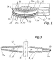
- the figures show variants of an electrical machine in the form of a disc rotor machine 10 .
- This disk rotor machine 10 has a rotor 14 and an at least partially corresponding stator 16.
- the rotor 14 has a carrier disk 14'
- the stator 16 here has two carrier disks 16' aligned axially with the central longitudinal axis of the rotor 14.
- the two carrier discs 16 'of the stand 16 carry in this variant shown each field coil 20, which in connection with the 2 , 2a - 2d are explained in more detail.
- the carrier disks 14' of the rotor 14 carry permanent magnets ⁇ , ⁇ .
- the rotor 14 and the stator 16, more precisely their respective carrier disks 14', 16' each have a mutually facing end face 14a, 14b; 16a, 16b.
- An air gap 18 is formed between the rotor carrier disk 14' and an adjacent stator carrier disk 16'.
- the field coils 20 or the permanent magnets ⁇ , ⁇ are aligned and arranged on the carrier disk 14' of each rotor 14 or the carrier disk 16' of each stator 16 in such a way that the field coils 20 and/or the permanent magnets ⁇ , ⁇ are at least temporarily cause magnetic fields in the same or opposite directions, which cause a rotary or longitudinal relative movement of the rotor 14 to the stator 16.
- the disc rotor machine 10 has iron-containing covers 22 on both of its end faces (top, bottom).
- the ferrous covers 22 are configured as magnetic flux return.
- the carrier disk 14' of each rotor 14 and the carrier disk 16' of each stator 16 are designed as multi-layer circuit boards made of glass fiber reinforced epoxy.
- the field coils 20 are here embedded in the carrier disk 16 ′ of each stator 16 and have a multi-phase configuration and contain copper conductor tracks with vias 20a.
- the space of the rotor 14 and/or the stator 16 located between or in the field coils 20 is ironless.
- Portions of the field coils 20 shown in phantom are embedded in the underside of the support disc 16' of each stator 16, the portions of the field coils 20 illustrated in solid are embedded in the top of the support disc 16' of each stator 16.
- the individual phases of the field coils 20 of the stator 16 are illustrated.
- the carrier discs 16 'of the stand 16 are omitted for better clarity.
- the course and the relative position of the stator field coils to one another can thus be clearly identified.
- the several phases of the stator field coils are thus aligned, spatially closely packed with the rotor permanent magnets located above/below them (see figure 3 ).
- the machine shaft 26 has a toothed section on which the carrier disks 14' of each rotor 14 are held in a rotationally fixed manner and so as to be movable in the axial direction.
- the stator support disks 16' are fixed against rotation on four pivots on one of the covers 22 and also longitudinally displaceable.
- the rotor carrier disks 14 ′ of the rotor 14 and the stator carrier disks 16 ′ are thus arranged such that they can move in relation to one another in the axial direction along the machine shaft 26 .
- each stand 16 is designed as a circular ring, which in the variant shown lacks a circular segment KA to the full circle.
- the field coils 20 of each stator 16 have radial sections 20-R as well as inner 20-I and Au peripheral sections 20-A, with the outer peripheral sections of the field coils 20 in the area of the missing circular section KA of the annulus having a have higher electrical resistance than the outer-circumferential sections of the field coils 20 in the area without a missing circular section KA of the annulus.
- outer peripheral sections 20-A of the field coils 20 are not raised, as is the case on the rest of the outer circumference of the field coils 20, but are formed from lower, simpler layers because they are still within the trajectory of the runner 16 are.
- the outer-beta peripheral sections 20-A of the field coils 20 in the area without a missing circular section KA of the circular ring are designed as end connectors that are raised in the axial direction compared to the area with a missing circular section KA of the circular ring.
- the outer peripheral portions 20-A of the field coils 20 in the area with no missing circular portion KA of the annulus are formed with multi-layered conductor material, compared to the area with missing circular portion KA with less-layered conductor material.
- the carrier disk of the rotor 16 has a flight circle diameter that at least approximately coincides with the distance AS of a chord S of the missing circular section KA of the annulus from the center Z of the annulus KS of the carrier disk of the stator 18 .
- the circular ring of the carrier disk 14' of each rotor 14 and/or the circular ring of the carrier disk 16' of each stator 16 can also have a polygonal ring shape, deviating from the circular shape shown.
- a plurality of single-phase field coils 20 of the stator 16 are arranged offset to one another along the circumference of the support disk of the stator 16 .
- the outer peripheral sections 20-A of the multiple individual phases of the field coils 20 are arranged here without crossing each other.
- the field coils 20 of the stator 16 can be operated as a Y- or ⁇ -connected arrangement, or can be fed individually. In particular, the spatial arrangement of the field coils 20 to the different poled individual segments of the permanent magnets ⁇ , ⁇ of the rotor 14 the phase association. As in 2 As illustrated, the radial portions 20-R of the field coils 20 of each stator 16 extend substantially between the areas of the inner perimeter portions 20-I to the areas of the outer perimeter portions 20-A.
- a conductor section 20-S is arranged on an outer lateral surface of the carrier disc 16' of the stator 16. This also makes it possible to connect the radial sections 20-R of the field coils 20 on the upper side of the carrier disk 16' of the stator 16 to the radial sections 20-R of the field coils 20 on the underside of the carrier disk 16' of the stator 16 in order to to form the field coils.
- the rotor 14 with the permanent magnets ⁇ , ⁇ has an iron disk 14', on which thin magnetic poles are glued on both sides.
- the thin magnetic poles can be easily magnetized as a whole disc.
- the superimposed magnetic poles are oriented in opposite directions, so that the magnetic flux to the next pole closes between them via the iron disk 14'.
- the electric current directed in the opposite direction produces a torque directed in the same direction of rotation as the electric current on the upper side of the iron disc 14'.
- the conductor sections 20-S acting as end connectors on the outer lateral surface of the carrier disk 16' are preferably short and wide.
- the conductor sections of the multilayer layers forming the field coils are all connected in parallel in each stator 16 .
- the conductor sections 20-S acting as end connectors extend from the field coil sections of a first stator to the field coil sections of a second stator.
- the end connectors 20-S run diagonally here so that the reverse current is routed under the neighboring magnets. Because of the greater distance than with one-sided return (see Figure 2c ) the cross-section of the connector is cheaper.
- the conductor sections of the multilayer layers forming the field coils are all connected in parallel in each stator 16 .
- the vias are also replaced by end connectors in the form of conductor sections 20-S located on the circumference of the stator disk.
- edge connectors are used instead of the vias achieves an improvement in the torque that can be achieved, because the straight, radial conductor sections 20-R reach to the edge of the stator disk.
- the stator 16 has a top and bottom surface with radial conductor sections 20-R for carrying current there and back.
- a in Fig. 2d illustrated forehead connector band is produced in a frame, for example, in etching technology or in laser cutting or stamping technology.
- the end connector band is soldered to the end face of the radial conductor sections 20-R while it is still in the frame.
- the frame is then separated from the end connectors 20-S at the bottlenecks E.
- successive radial sections 20-R of the field coils 20 of the stator 16 are distributed over two carrier disks 16' of the stator 16 which are adjacent in the axial direction and are not shown in this illustration for the sake of clarity.
- Conductor pieces 20-S oriented obliquely on the circumference contact the radial sections 20-R of the field coils 20 of each stator 16 on the respective lateral surfaces of the adjacent carrier disk 16' of the stator 16.
- a special solution for the end connectors is particularly effective on the outer circumference, as there is a torque advantage is usable.
- this connection is only possible radially on the outside because of the shaft.
- the field coils 20 of the stator 16 are formed from a number of individual circuit boards which have copper-containing layers on both sides. In order to obtain a conductor cross-section required for a given current-carrying capacity, a solder layer, a sintered layer and/or copper foil are arranged between two copper-containing layers of adjacent circuit boards.
- two conductors are approximately the same length and a third conductor is arranged between the two conductors of approximately the same length and projects beyond them in the radial direction.
- one of the two conductors of approximately equal length has a cross-connection on one side and the other of the two approximately equal-length conductors has a cross-connection on the other side of the conductor surface.
- the third conductor has a cross-connection on both sides radially on the inside, and the three conductors are electrically contacted with their cross-connections.
- the dimensions and cross-sections of the three conductors and their cross-connections are dimensioned such that the electrical resistances of the respective field coils 20 of the stator 16 are at least approximately the same.
- the three conductors and their interconnections are interconnected by rows or arrays of vias in the manner of open or capped thermal vias.
- the radial sections 20-R of the individual field coils 20 are approximately one- nth the height of the inner and outer peripheral sections 20-I, 20-A. Where n is the number of individual field coils 20 on the carrier disk 16' of the stator 16.
- the electric disk rotor machine is assigned sensor coils of an inductive angle measuring system of the circuit board radially inside the inner peripheral sections 20-I of the individual field coils 20 of the stator 16, on/in/under which the field coils 20 are arranged are. These sensor coils of the inductive angle measuring system are connected to a controller.
- the carrier disk 14' of the rotor 14 is assigned inductive structures which interact with the sensor coils (and are separated by the air gap 18).
- each rotor 14 is formed as a circular ring.
- the permanent magnets ⁇ , ⁇ are at least partially embedded in the carrier disk 14′ of each rotor 14 .
- at least partially embedded, single-phase or multi-phase conductor tracks can also be provided as runner field coils.
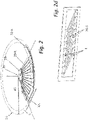
- the carrier disc 14' of each rotor 14 has an axial height near the center which is higher than at the outer edge of the carrier disc.
- the permanent magnets ⁇ , ⁇ or rotor field coils are at least partially embedded in the carrier disk 14′ of each rotor 14 in such a way that the axial height of the circular ring is higher near the center of the carrier disk than at the outer edge of the carrier disk.
- the angle W which the upper and the lower surface of the carrier disc 14' of the rotor 14 enclose, is between 3° and 30°.
- a variant is shown on the left side of the figure, in which the change in the axial height in the radial direction is concentrically stepless, while in 3 on the right side of the figure a variant not belonging to the invention is shown, in which the variation of the axial height is graduated in the radial direction.
- the rotor 14 has a disk made of steel, which is connected to the machine shaft 26 in a torque-proof manner.
- the steel disk carries the permanent magnets ⁇ , ⁇ on at least one of its two sides, which are preferably designed as cylinder or cone ring segments. Rotor field coils can also be provided instead of the magnets.
- Permanent magnets arranged on both sides of the disc of the rotor 14 and aligned with one another in the axial direction each have the same or opposite magnetic orientation.
- oppositely oriented permanent magnets are arranged on the disc of the rotor 14 on both sides.
- the disc 14' of the rotor 14 is designed in one piece with the machine shaft in a variant which does not belong to the invention.
- the permanent magnets arranged on both sides are designed as thin magnetic disks, and the axial height of the carrier disk of rotor 14 decreasing towards the outer edge is essentially achieved by decreasing thickness of the disk of rotor 14 with essentially the same thickness of the permanent magnets.
- the disc of the rotor 14 has an annular sliding bearing 14a on the outer circumference.
- a groove is machined into the outer edge of the disc, into which several sliding pieces 14b, which are fixed to the housing and distributed around the circumference, engage.
- the carrier disk 16' of the stator 16 and ferromagnetic yoke parts 22 and a housing are divided into two (or more) parts in the axial direction (or at an angle to the longitudinal center axis of the disk rotor machine).
- the individual parts of the carrier disc 16 ′ and the return path parts are introduced into the respective housing parts with a positive and/or material connection.
- In 1 is further illustrated how two support disks of the stator 16 receive a disk of the rotor 14 between them in the axial direction.
- the two carrier disks of the stator 16 are mounted so that they can move in the axial direction together with their respective ferromagnetic yoke 22 .
- the stator coils are energized during operation, the two carrier disks of the stator 16 are attracted to the disk of the rotor 14 .
- At least one draw/hold coil 38 is arranged on both sides of the disk of the rotor 14 in the ferromagnetic yokes 22 or the housing 36 of the disk rotor machine.
- these pull/hold coils 38 are energized accordingly, they act together with the ferromagnetic yokes 22 or the housing 36 pull/hold coils 38 and the ferromagnetic yokes 22 or the housing 36 like lifting magnets and pull the two carrier disks of the stator 16 from the disk of the runner 14 at a distance and hold it in this position. Since the machine is usually only in operation for a short time, the operation of the lifting magnets does not represent an excessive load.
- the permanent magnets ⁇ , ⁇ of the rotor 14 and the coils 20 of the stator 16 are separated from one another by an insulating layer. Furthermore, each of the discs of the stator 16, the ferromagnetic yokes 22 and the disc of the rotor 14 are axially supported and provided with stops relative to one another so that each of the discs of the stator 16 is attracted to the corresponding one of the ferromagnetic yokes 22 in the attracted state abuts, and each of the discs of the stand 16 opposite of the disk of the rotor 14 maintains an air gap of approximately 0.1 mm to approximately 0.3 mm during operation.
- Permanent magnets ⁇ , ⁇ are embedded or at least partially exposed permanent magnets ⁇ , ⁇ are provided in the carrier disk 14′ of each rotor 14 or each stator 16, which are approximately 0.5 to 3 times, preferably one to twice as high in the axial direction the air gap is 18.
- the permanent magnets ⁇ , ⁇ are preferably side earth magnets.
- the stator 16 has three-phase or higher-phase stator coils 20.
- a rotor bearing disk is connected to a housing, or the rotor bearing disk forms at least one section of the housing.
Landscapes
- Engineering & Computer Science (AREA)
- Power Engineering (AREA)
- Permanent Magnet Type Synchronous Machine (AREA)
Applications Claiming Priority (1)
| Application Number | Priority Date | Filing Date | Title |
|---|---|---|---|
| DE102018009959.9A DE102018009959B4 (de) | 2018-12-18 | 2018-12-18 | Elektrische Scheibenläufermaschine |
Publications (2)
| Publication Number | Publication Date |
|---|---|
| EP3672041A1 EP3672041A1 (de) | 2020-06-24 |
| EP3672041B1 true EP3672041B1 (de) | 2022-06-15 |
Family
ID=68426237
Family Applications (1)
| Application Number | Title | Priority Date | Filing Date |
|---|---|---|---|
| EP19206799.9A Active EP3672041B1 (de) | 2018-12-18 | 2019-11-04 | Elektrische scheibenläufermaschine |
Country Status (3)
| Country | Link |
|---|---|
| EP (1) | EP3672041B1 (pl) |
| DE (1) | DE102018009959B4 (pl) |
| PL (1) | PL3672041T3 (pl) |
Families Citing this family (2)
| Publication number | Priority date | Publication date | Assignee | Title |
|---|---|---|---|---|
| DE102020216121A1 (de) | 2020-12-17 | 2022-06-23 | Zf Friedrichshafen Ag | Scheibenläufermotor, insbesondere für ein Kraftfahrzeug |
| CN112821586A (zh) * | 2021-02-03 | 2021-05-18 | 福一开集团有限公司 | 一种单相交流电动机和发电机一体机 |
Family Cites Families (6)
| Publication number | Priority date | Publication date | Assignee | Title |
|---|---|---|---|---|
| DE3526166C2 (de) * | 1984-07-23 | 1996-05-02 | Asahi Chemical Ind | Bürstenloser Elektromotor und Verfahren zum Herstellen einer Spuleneinheit für diesen |
| US6348751B1 (en) * | 1997-12-12 | 2002-02-19 | New Generation Motors Corporation | Electric motor with active hysteresis-based control of winding currents and/or having an efficient stator winding arrangement and/or adjustable air gap |
| JP4394115B2 (ja) * | 2006-12-26 | 2010-01-06 | 本田技研工業株式会社 | アキシャルギャップ型モータ |
| US8726490B2 (en) * | 2011-08-18 | 2014-05-20 | Glassy Metal Technologies Ltd. | Method of constructing core with tapered pole pieces and low-loss electrical rotating machine with said core |
| US11121596B2 (en) * | 2016-02-29 | 2021-09-14 | Denso Corporation | Stator of brushless motor, brushless motor, and method of manufacturing stator of brushless motor |
| DE102016004694B4 (de) | 2016-04-19 | 2020-03-12 | eMoSys GmbH | Elektronisch gesteuerter Gurtautomat eines Fahrzeuginsassenrückhaltesystems |
-
2018
- 2018-12-18 DE DE102018009959.9A patent/DE102018009959B4/de active Active
-
2019
- 2019-11-04 PL PL19206799.9T patent/PL3672041T3/pl unknown
- 2019-11-04 EP EP19206799.9A patent/EP3672041B1/de active Active
Also Published As
| Publication number | Publication date |
|---|---|
| PL3672041T3 (pl) | 2022-12-19 |
| DE102018009959B4 (de) | 2024-08-01 |
| EP3672041A1 (de) | 2020-06-24 |
| DE102018009959A1 (de) | 2020-06-18 |
Similar Documents
| Publication | Publication Date | Title |
|---|---|---|
| DE69724883T2 (de) | Reluktanzmotor mit Magnetpole, die aus in der Umfangsrichtung angeordneten Blechpakete bestehen | |
| DE69222014T2 (de) | Kernloser gleichstrommotor in flachbauweise | |
| DE69616319T2 (de) | Elektromagnetischer betätiger | |
| DE60315044T2 (de) | Wellgetriebemotor | |
| WO2019038080A1 (de) | Leistungsübertragungssystem zum erzeugen eines stroms in einer erregerwicklung eines rotors einer elektrischen maschine sowie elektrische maschine und kraftfahrzeug | |
| DE102021003942B4 (de) | Stator für eine Radialfluss-Doppelrotormaschine, Radialfluss-Doppelrotormaschine und Verfahren zur Herstellung eines Stators für eine Radialfluss-Doppelrotormaschine | |
| DE102011111352B4 (de) | Elektromotor mit eisenloser Wicklung | |
| WO2021003510A2 (de) | Stator für eine axialflussmaschine | |
| DE10309776A1 (de) | Innenläufermotor | |
| EP0680133A1 (de) | Elektronisch kommutierte Gleichstrommaschine | |
| DE102004030063A1 (de) | Permanentmagneterregte Drehfeldmaschine | |
| EP3522336A1 (de) | Rotor | |
| EP3659240B1 (de) | Rotor einer elektrischen maschine | |
| DE60007936T2 (de) | Motor/Generator mit zwei Rotoren | |
| DE102015206697A1 (de) | Primärteil einer elektrischen Maschine, elektrische Maschine und Verfahren zur Herstellung eines Primärteils | |
| DE69814356T2 (de) | Bürstenloser permanenterregter Elektromotor | |
| EP3672041B1 (de) | Elektrische scheibenläufermaschine | |
| EP2115856A2 (de) | Elektromotor, spulenelement für einen solchen motor und verfahren zum herstellen eines spulenelements | |
| EP1445433A1 (de) | Ventilantrieb für einen ventilgesteuerten Verbrennungsmotor | |
| EP3669440B1 (de) | Rotor einer elektrischen maschine | |
| DE4419780C2 (de) | Ringförmiger Stator für elektrodynamische Drehmaschine | |
| WO2021190686A1 (de) | Manipulatorarm für einen roboter sowie roboter mit einem solchen manipulatorarm | |
| DE102014001023B4 (de) | Elektrische Maschine | |
| EP2790297B1 (de) | Läufer für eine elektrische Maschine | |
| DE102018104418A1 (de) | Elektromagnetisch betätigter Aktor für elektrische Maschine und elektrische Maschine mit elektromagnetisch betätigtem Aktor |
Legal Events
| Date | Code | Title | Description |
|---|---|---|---|
| PUAI | Public reference made under article 153(3) epc to a published international application that has entered the european phase |
Free format text: ORIGINAL CODE: 0009012 |
|
| STAA | Information on the status of an ep patent application or granted ep patent |
Free format text: STATUS: THE APPLICATION HAS BEEN PUBLISHED |
|
| AK | Designated contracting states |
Kind code of ref document: A1 Designated state(s): AL AT BE BG CH CY CZ DE DK EE ES FI FR GB GR HR HU IE IS IT LI LT LU LV MC MK MT NL NO PL PT RO RS SE SI SK SM TR |
|
| AX | Request for extension of the european patent |
Extension state: BA ME |
|
| STAA | Information on the status of an ep patent application or granted ep patent |
Free format text: STATUS: REQUEST FOR EXAMINATION WAS MADE |
|
| 17P | Request for examination filed |
Effective date: 20201211 |
|
| RBV | Designated contracting states (corrected) |
Designated state(s): AL AT BE BG CH CY CZ DE DK EE ES FI FR GB GR HR HU IE IS IT LI LT LU LV MC MK MT NL NO PL PT RO RS SE SI SK SM TR |
|
| GRAJ | Information related to disapproval of communication of intention to grant by the applicant or resumption of examination proceedings by the epo deleted |
Free format text: ORIGINAL CODE: EPIDOSDIGR1 |
|
| GRAP | Despatch of communication of intention to grant a patent |
Free format text: ORIGINAL CODE: EPIDOSNIGR1 |
|
| GRAJ | Information related to disapproval of communication of intention to grant by the applicant or resumption of examination proceedings by the epo deleted |
Free format text: ORIGINAL CODE: EPIDOSDIGR1 |
|
| STAA | Information on the status of an ep patent application or granted ep patent |
Free format text: STATUS: GRANT OF PATENT IS INTENDED |
|
| GRAP | Despatch of communication of intention to grant a patent |
Free format text: ORIGINAL CODE: EPIDOSNIGR1 |
|
| INTG | Intention to grant announced |
Effective date: 20211215 |
|
| INTC | Intention to grant announced (deleted) | ||
| INTG | Intention to grant announced |
Effective date: 20220107 |
|
| GRAS | Grant fee paid |
Free format text: ORIGINAL CODE: EPIDOSNIGR3 |
|
| GRAA | (expected) grant |
Free format text: ORIGINAL CODE: 0009210 |
|
| STAA | Information on the status of an ep patent application or granted ep patent |
Free format text: STATUS: THE PATENT HAS BEEN GRANTED |
|
| AK | Designated contracting states |
Kind code of ref document: B1 Designated state(s): AL AT BE BG CH CY CZ DE DK EE ES FI FR GB GR HR HU IE IS IT LI LT LU LV MC MK MT NL NO PL PT RO RS SE SI SK SM TR |
|
| REG | Reference to a national code |
Ref country code: CH Ref legal event code: EP Ref country code: GB Ref legal event code: FG4D Free format text: NOT ENGLISH |
|
| REG | Reference to a national code |
Ref country code: IE Ref legal event code: FG4D Free format text: LANGUAGE OF EP DOCUMENT: GERMAN |
|
| REG | Reference to a national code |
Ref country code: DE Ref legal event code: R096 Ref document number: 502019004638 Country of ref document: DE |
|
| REG | Reference to a national code |
Ref country code: AT Ref legal event code: REF Ref document number: 1498996 Country of ref document: AT Kind code of ref document: T Effective date: 20220715 |
|
| REG | Reference to a national code |
Ref country code: LT Ref legal event code: MG9D |
|
| REG | Reference to a national code |
Ref country code: NL Ref legal event code: MP Effective date: 20220615 |
|
| PG25 | Lapsed in a contracting state [announced via postgrant information from national office to epo] |
Ref country code: SE Free format text: LAPSE BECAUSE OF FAILURE TO SUBMIT A TRANSLATION OF THE DESCRIPTION OR TO PAY THE FEE WITHIN THE PRESCRIBED TIME-LIMIT Effective date: 20220615 Ref country code: NO Free format text: LAPSE BECAUSE OF FAILURE TO SUBMIT A TRANSLATION OF THE DESCRIPTION OR TO PAY THE FEE WITHIN THE PRESCRIBED TIME-LIMIT Effective date: 20220915 Ref country code: LT Free format text: LAPSE BECAUSE OF FAILURE TO SUBMIT A TRANSLATION OF THE DESCRIPTION OR TO PAY THE FEE WITHIN THE PRESCRIBED TIME-LIMIT Effective date: 20220615 Ref country code: HR Free format text: LAPSE BECAUSE OF FAILURE TO SUBMIT A TRANSLATION OF THE DESCRIPTION OR TO PAY THE FEE WITHIN THE PRESCRIBED TIME-LIMIT Effective date: 20220615 Ref country code: GR Free format text: LAPSE BECAUSE OF FAILURE TO SUBMIT A TRANSLATION OF THE DESCRIPTION OR TO PAY THE FEE WITHIN THE PRESCRIBED TIME-LIMIT Effective date: 20220916 Ref country code: FI Free format text: LAPSE BECAUSE OF FAILURE TO SUBMIT A TRANSLATION OF THE DESCRIPTION OR TO PAY THE FEE WITHIN THE PRESCRIBED TIME-LIMIT Effective date: 20220615 Ref country code: BG Free format text: LAPSE BECAUSE OF FAILURE TO SUBMIT A TRANSLATION OF THE DESCRIPTION OR TO PAY THE FEE WITHIN THE PRESCRIBED TIME-LIMIT Effective date: 20220915 |
|
| PG25 | Lapsed in a contracting state [announced via postgrant information from national office to epo] |
Ref country code: RS Free format text: LAPSE BECAUSE OF FAILURE TO SUBMIT A TRANSLATION OF THE DESCRIPTION OR TO PAY THE FEE WITHIN THE PRESCRIBED TIME-LIMIT Effective date: 20220615 Ref country code: LV Free format text: LAPSE BECAUSE OF FAILURE TO SUBMIT A TRANSLATION OF THE DESCRIPTION OR TO PAY THE FEE WITHIN THE PRESCRIBED TIME-LIMIT Effective date: 20220615 |
|
| PG25 | Lapsed in a contracting state [announced via postgrant information from national office to epo] |
Ref country code: NL Free format text: LAPSE BECAUSE OF FAILURE TO SUBMIT A TRANSLATION OF THE DESCRIPTION OR TO PAY THE FEE WITHIN THE PRESCRIBED TIME-LIMIT Effective date: 20220615 |
|
| PG25 | Lapsed in a contracting state [announced via postgrant information from national office to epo] |
Ref country code: SM Free format text: LAPSE BECAUSE OF FAILURE TO SUBMIT A TRANSLATION OF THE DESCRIPTION OR TO PAY THE FEE WITHIN THE PRESCRIBED TIME-LIMIT Effective date: 20220615 Ref country code: SK Free format text: LAPSE BECAUSE OF FAILURE TO SUBMIT A TRANSLATION OF THE DESCRIPTION OR TO PAY THE FEE WITHIN THE PRESCRIBED TIME-LIMIT Effective date: 20220615 Ref country code: RO Free format text: LAPSE BECAUSE OF FAILURE TO SUBMIT A TRANSLATION OF THE DESCRIPTION OR TO PAY THE FEE WITHIN THE PRESCRIBED TIME-LIMIT Effective date: 20220615 Ref country code: PT Free format text: LAPSE BECAUSE OF FAILURE TO SUBMIT A TRANSLATION OF THE DESCRIPTION OR TO PAY THE FEE WITHIN THE PRESCRIBED TIME-LIMIT Effective date: 20221017 Ref country code: ES Free format text: LAPSE BECAUSE OF FAILURE TO SUBMIT A TRANSLATION OF THE DESCRIPTION OR TO PAY THE FEE WITHIN THE PRESCRIBED TIME-LIMIT Effective date: 20220615 Ref country code: EE Free format text: LAPSE BECAUSE OF FAILURE TO SUBMIT A TRANSLATION OF THE DESCRIPTION OR TO PAY THE FEE WITHIN THE PRESCRIBED TIME-LIMIT Effective date: 20220615 Ref country code: CZ Free format text: LAPSE BECAUSE OF FAILURE TO SUBMIT A TRANSLATION OF THE DESCRIPTION OR TO PAY THE FEE WITHIN THE PRESCRIBED TIME-LIMIT Effective date: 20220615 |
|
| PG25 | Lapsed in a contracting state [announced via postgrant information from national office to epo] |
Ref country code: IS Free format text: LAPSE BECAUSE OF FAILURE TO SUBMIT A TRANSLATION OF THE DESCRIPTION OR TO PAY THE FEE WITHIN THE PRESCRIBED TIME-LIMIT Effective date: 20221015 |
|
| REG | Reference to a national code |
Ref country code: DE Ref legal event code: R097 Ref document number: 502019004638 Country of ref document: DE |
|
| PG25 | Lapsed in a contracting state [announced via postgrant information from national office to epo] |
Ref country code: AL Free format text: LAPSE BECAUSE OF FAILURE TO SUBMIT A TRANSLATION OF THE DESCRIPTION OR TO PAY THE FEE WITHIN THE PRESCRIBED TIME-LIMIT Effective date: 20220615 |
|
| PLBE | No opposition filed within time limit |
Free format text: ORIGINAL CODE: 0009261 |
|
| STAA | Information on the status of an ep patent application or granted ep patent |
Free format text: STATUS: NO OPPOSITION FILED WITHIN TIME LIMIT |
|
| PG25 | Lapsed in a contracting state [announced via postgrant information from national office to epo] |
Ref country code: DK Free format text: LAPSE BECAUSE OF FAILURE TO SUBMIT A TRANSLATION OF THE DESCRIPTION OR TO PAY THE FEE WITHIN THE PRESCRIBED TIME-LIMIT Effective date: 20220615 |
|
| 26N | No opposition filed |
Effective date: 20230316 |
|
| PG25 | Lapsed in a contracting state [announced via postgrant information from national office to epo] |
Ref country code: SI Free format text: LAPSE BECAUSE OF FAILURE TO SUBMIT A TRANSLATION OF THE DESCRIPTION OR TO PAY THE FEE WITHIN THE PRESCRIBED TIME-LIMIT Effective date: 20220615 |
|
| PG25 | Lapsed in a contracting state [announced via postgrant information from national office to epo] |
Ref country code: MC Free format text: LAPSE BECAUSE OF FAILURE TO SUBMIT A TRANSLATION OF THE DESCRIPTION OR TO PAY THE FEE WITHIN THE PRESCRIBED TIME-LIMIT Effective date: 20220615 |
|
| REG | Reference to a national code |
Ref country code: CH Ref legal event code: PL |
|
| P01 | Opt-out of the competence of the unified patent court (upc) registered |
Effective date: 20230525 |
|
| REG | Reference to a national code |
Ref country code: BE Ref legal event code: MM Effective date: 20221130 |
|
| PG25 | Lapsed in a contracting state [announced via postgrant information from national office to epo] |
Ref country code: LI Free format text: LAPSE BECAUSE OF NON-PAYMENT OF DUE FEES Effective date: 20221130 Ref country code: CH Free format text: LAPSE BECAUSE OF NON-PAYMENT OF DUE FEES Effective date: 20221130 |
|
| PG25 | Lapsed in a contracting state [announced via postgrant information from national office to epo] |
Ref country code: LU Free format text: LAPSE BECAUSE OF NON-PAYMENT OF DUE FEES Effective date: 20221104 |
|
| PG25 | Lapsed in a contracting state [announced via postgrant information from national office to epo] |
Ref country code: IE Free format text: LAPSE BECAUSE OF NON-PAYMENT OF DUE FEES Effective date: 20221104 |
|
| PG25 | Lapsed in a contracting state [announced via postgrant information from national office to epo] |
Ref country code: BE Free format text: LAPSE BECAUSE OF NON-PAYMENT OF DUE FEES Effective date: 20221130 |
|
| PG25 | Lapsed in a contracting state [announced via postgrant information from national office to epo] |
Ref country code: HU Free format text: LAPSE BECAUSE OF FAILURE TO SUBMIT A TRANSLATION OF THE DESCRIPTION OR TO PAY THE FEE WITHIN THE PRESCRIBED TIME-LIMIT; INVALID AB INITIO Effective date: 20191104 |
|
| PG25 | Lapsed in a contracting state [announced via postgrant information from national office to epo] |
Ref country code: CY Free format text: LAPSE BECAUSE OF FAILURE TO SUBMIT A TRANSLATION OF THE DESCRIPTION OR TO PAY THE FEE WITHIN THE PRESCRIBED TIME-LIMIT Effective date: 20220615 |
|
| PG25 | Lapsed in a contracting state [announced via postgrant information from national office to epo] |
Ref country code: MK Free format text: LAPSE BECAUSE OF FAILURE TO SUBMIT A TRANSLATION OF THE DESCRIPTION OR TO PAY THE FEE WITHIN THE PRESCRIBED TIME-LIMIT Effective date: 20220615 |
|
| PG25 | Lapsed in a contracting state [announced via postgrant information from national office to epo] |
Ref country code: TR Free format text: LAPSE BECAUSE OF FAILURE TO SUBMIT A TRANSLATION OF THE DESCRIPTION OR TO PAY THE FEE WITHIN THE PRESCRIBED TIME-LIMIT Effective date: 20220615 |
|
| PG25 | Lapsed in a contracting state [announced via postgrant information from national office to epo] |
Ref country code: MT Free format text: LAPSE BECAUSE OF FAILURE TO SUBMIT A TRANSLATION OF THE DESCRIPTION OR TO PAY THE FEE WITHIN THE PRESCRIBED TIME-LIMIT Effective date: 20220615 |
|
| PG25 | Lapsed in a contracting state [announced via postgrant information from national office to epo] |
Ref country code: BG Free format text: LAPSE BECAUSE OF FAILURE TO SUBMIT A TRANSLATION OF THE DESCRIPTION OR TO PAY THE FEE WITHIN THE PRESCRIBED TIME-LIMIT Effective date: 20220615 |
|
| PG25 | Lapsed in a contracting state [announced via postgrant information from national office to epo] |
Ref country code: BG Free format text: LAPSE BECAUSE OF FAILURE TO SUBMIT A TRANSLATION OF THE DESCRIPTION OR TO PAY THE FEE WITHIN THE PRESCRIBED TIME-LIMIT Effective date: 20220615 |
|
| PGFP | Annual fee paid to national office [announced via postgrant information from national office to epo] |
Ref country code: DE Payment date: 20251118 Year of fee payment: 7 |
|
| PGFP | Annual fee paid to national office [announced via postgrant information from national office to epo] |
Ref country code: GB Payment date: 20251120 Year of fee payment: 7 |
|
| PG25 | Lapsed in a contracting state [announced via postgrant information from national office to epo] |
Ref country code: AT Free format text: LAPSE BECAUSE OF NON-PAYMENT OF DUE FEES Effective date: 20241104 |
|
| PGFP | Annual fee paid to national office [announced via postgrant information from national office to epo] |
Ref country code: IT Payment date: 20251128 Year of fee payment: 7 |
|
| PGFP | Annual fee paid to national office [announced via postgrant information from national office to epo] |
Ref country code: FR Payment date: 20251125 Year of fee payment: 7 |
|
| REG | Reference to a national code |
Ref country code: AT Ref legal event code: MM01 Ref document number: 1498996 Country of ref document: AT Kind code of ref document: T Effective date: 20241104 |
|
| PGFP | Annual fee paid to national office [announced via postgrant information from national office to epo] |
Ref country code: PL Payment date: 20251023 Year of fee payment: 7 |