EP3672041B1 - Electric disk rotor machine - Google Patents
Electric disk rotor machine Download PDFInfo
- Publication number
- EP3672041B1 EP3672041B1 EP19206799.9A EP19206799A EP3672041B1 EP 3672041 B1 EP3672041 B1 EP 3672041B1 EP 19206799 A EP19206799 A EP 19206799A EP 3672041 B1 EP3672041 B1 EP 3672041B1
- Authority
- EP
- European Patent Office
- Prior art keywords
- rotor
- stator
- field coils
- disc
- permanent magnets
- Prior art date
- Legal status (The legal status is an assumption and is not a legal conclusion. Google has not performed a legal analysis and makes no representation as to the accuracy of the status listed.)
- Active
Links
- 239000004020 conductor Substances 0.000 claims description 67
- 230000005291 magnetic effect Effects 0.000 claims description 30
- 230000005294 ferromagnetic effect Effects 0.000 claims description 22
- 239000010410 layer Substances 0.000 claims description 22
- RYGMFSIKBFXOCR-UHFFFAOYSA-N Copper Chemical compound [Cu] RYGMFSIKBFXOCR-UHFFFAOYSA-N 0.000 claims description 16
- 229910052802 copper Inorganic materials 0.000 claims description 13
- 239000010949 copper Substances 0.000 claims description 13
- 239000000463 material Substances 0.000 claims description 10
- 238000004519 manufacturing process Methods 0.000 claims description 7
- 238000003780 insertion Methods 0.000 claims description 6
- 230000037431 insertion Effects 0.000 claims description 6
- 229910052782 aluminium Inorganic materials 0.000 claims description 4
- XAGFODPZIPBFFR-UHFFFAOYSA-N aluminium Chemical compound [Al] XAGFODPZIPBFFR-UHFFFAOYSA-N 0.000 claims description 4
- 238000003491 array Methods 0.000 claims description 4
- 239000011889 copper foil Substances 0.000 claims description 3
- 229910000679 solder Inorganic materials 0.000 claims description 3
- 239000005030 aluminium foil Substances 0.000 claims 1
- XEEYBQQBJWHFJM-UHFFFAOYSA-N Iron Chemical compound [Fe] XEEYBQQBJWHFJM-UHFFFAOYSA-N 0.000 description 30
- 229910052742 iron Inorganic materials 0.000 description 15
- 230000002093 peripheral effect Effects 0.000 description 12
- 229910000831 Steel Inorganic materials 0.000 description 10
- 239000010959 steel Substances 0.000 description 10
- 238000004804 winding Methods 0.000 description 10
- CWYNVVGOOAEACU-UHFFFAOYSA-N Fe2+ Chemical compound [Fe+2] CWYNVVGOOAEACU-UHFFFAOYSA-N 0.000 description 7
- 230000008901 benefit Effects 0.000 description 7
- 230000004907 flux Effects 0.000 description 6
- 238000000034 method Methods 0.000 description 6
- 230000005284 excitation Effects 0.000 description 5
- 230000001939 inductive effect Effects 0.000 description 5
- 230000003247 decreasing effect Effects 0.000 description 4
- 238000013461 design Methods 0.000 description 4
- 229910052761 rare earth metal Inorganic materials 0.000 description 4
- 150000002910 rare earth metals Chemical class 0.000 description 4
- 230000000694 effects Effects 0.000 description 3
- 210000001061 forehead Anatomy 0.000 description 3
- 229910052751 metal Inorganic materials 0.000 description 3
- 239000002184 metal Substances 0.000 description 3
- 239000004593 Epoxy Substances 0.000 description 2
- 239000000919 ceramic Substances 0.000 description 2
- 230000008859 change Effects 0.000 description 2
- 238000006243 chemical reaction Methods 0.000 description 2
- 238000000576 coating method Methods 0.000 description 2
- 238000006073 displacement reaction Methods 0.000 description 2
- 238000005516 engineering process Methods 0.000 description 2
- 238000009434 installation Methods 0.000 description 2
- 239000004033 plastic Substances 0.000 description 2
- 229920003023 plastic Polymers 0.000 description 2
- 238000004092 self-diagnosis Methods 0.000 description 2
- 239000002356 single layer Substances 0.000 description 2
- OKTJSMMVPCPJKN-UHFFFAOYSA-N Carbon Chemical compound [C] OKTJSMMVPCPJKN-UHFFFAOYSA-N 0.000 description 1
- 229920002430 Fibre-reinforced plastic Polymers 0.000 description 1
- 239000004642 Polyimide Substances 0.000 description 1
- 230000001133 acceleration Effects 0.000 description 1
- 230000009471 action Effects 0.000 description 1
- 230000004323 axial length Effects 0.000 description 1
- 230000005540 biological transmission Effects 0.000 description 1
- 230000015572 biosynthetic process Effects 0.000 description 1
- 229910052799 carbon Inorganic materials 0.000 description 1
- 239000011248 coating agent Substances 0.000 description 1
- 238000010276 construction Methods 0.000 description 1
- 238000001816 cooling Methods 0.000 description 1
- 238000011161 development Methods 0.000 description 1
- 230000018109 developmental process Effects 0.000 description 1
- 238000005530 etching Methods 0.000 description 1
- 239000011888 foil Substances 0.000 description 1
- 239000003365 glass fiber Substances 0.000 description 1
- 229910052737 gold Inorganic materials 0.000 description 1
- 210000003128 head Anatomy 0.000 description 1
- 230000006872 improvement Effects 0.000 description 1
- 230000006698 induction Effects 0.000 description 1
- 238000003475 lamination Methods 0.000 description 1
- 238000003698 laser cutting Methods 0.000 description 1
- 230000013011 mating Effects 0.000 description 1
- 238000005259 measurement Methods 0.000 description 1
- 230000005226 mechanical processes and functions Effects 0.000 description 1
- 238000001465 metallisation Methods 0.000 description 1
- 150000002739 metals Chemical class 0.000 description 1
- 238000012986 modification Methods 0.000 description 1
- 230000004048 modification Effects 0.000 description 1
- 238000012544 monitoring process Methods 0.000 description 1
- 229910001172 neodymium magnet Inorganic materials 0.000 description 1
- 230000010363 phase shift Effects 0.000 description 1
- 229920001721 polyimide Polymers 0.000 description 1
- 239000004810 polytetrafluoroethylene Substances 0.000 description 1
- 229920001343 polytetrafluoroethylene Polymers 0.000 description 1
- 239000012256 powdered iron Substances 0.000 description 1
- 230000009467 reduction Effects 0.000 description 1
- 230000003014 reinforcing effect Effects 0.000 description 1
- 230000001846 repelling effect Effects 0.000 description 1
- 230000004044 response Effects 0.000 description 1
- 239000004065 semiconductor Substances 0.000 description 1
- 238000010008 shearing Methods 0.000 description 1
- 239000007787 solid Substances 0.000 description 1
- 238000012360 testing method Methods 0.000 description 1
- 229910000859 α-Fe Inorganic materials 0.000 description 1
Images

Classifications
-
- H—ELECTRICITY
- H02—GENERATION; CONVERSION OR DISTRIBUTION OF ELECTRIC POWER
- H02K—DYNAMO-ELECTRIC MACHINES
- H02K1/00—Details of the magnetic circuit
- H02K1/06—Details of the magnetic circuit characterised by the shape, form or construction
- H02K1/22—Rotating parts of the magnetic circuit
- H02K1/27—Rotor cores with permanent magnets
- H02K1/2793—Rotors axially facing stators
- H02K1/2795—Rotors axially facing stators the rotor consisting of two or more circumferentially positioned magnets
-
- H—ELECTRICITY
- H02—GENERATION; CONVERSION OR DISTRIBUTION OF ELECTRIC POWER
- H02K—DYNAMO-ELECTRIC MACHINES
- H02K21/00—Synchronous motors having permanent magnets; Synchronous generators having permanent magnets
- H02K21/12—Synchronous motors having permanent magnets; Synchronous generators having permanent magnets with stationary armatures and rotating magnets
- H02K21/24—Synchronous motors having permanent magnets; Synchronous generators having permanent magnets with stationary armatures and rotating magnets with magnets axially facing the armatures, e.g. hub-type cycle dynamos
-
- H—ELECTRICITY
- H02—GENERATION; CONVERSION OR DISTRIBUTION OF ELECTRIC POWER
- H02K—DYNAMO-ELECTRIC MACHINES
- H02K2213/00—Specific aspects, not otherwise provided for and not covered by codes H02K2201/00 - H02K2211/00
- H02K2213/03—Machines characterised by numerical values, ranges, mathematical expressions or similar information
Definitions
- an electric disc rotor machine which is more suitable and intended for use in a vehicle, as a drive in a robot arm or for positioning machine parts and the like, for example.
- This can also be an electrical machine that is suitable and provided as an auxiliary or ancillary unit in the vehicle or aircraft.
- Electric machines are used in a variety of industrial, mobility, and comfort/safety applications. There is often a requirement for a compact, lightweight machine that can perform a rotary movement of a few hundred degrees to several (about ten) full revolutions with minimal delay with high torque. Another requirement is good suitability for operating the machine with a multi-phase power electronic actuator (converter or inverter).
- a multi-phase power electronic actuator converter or inverter.
- disk rotors especially permanent magnet machines, have mostly been found in special applications such as gearless, low-speed torque machines.
- disc rotor machines are primarily used when a small length-diameter ratio is required.
- the document DE 11 2017 001 053 T5 discloses an electric machine having a stator core and a plurality of coils.
- the stator core has a base portion in an annular plate shape and a plurality of teeth protruding in an axial direction from a surface of the base portion and arranged in a circumferential direction.
- the multiple coils are each wound by concentrated winding along peripheral surfaces of the multiple teeth.
- the base portion has an inner peripheral edge indented radially outward from an inner end of each of the plurality of teeth, or the base portion has an outer peripheral edge indented radially inward from an outer end of each of the plurality of teeth.
- the task to be solved is to provide an electrical machine that allows efficient, safe operation in a small space.
- a significantly higher output can be achieved with this design than with a machine with a circular cross section, the outer circumference of which corresponds to the inscribed circle of the polygonal profile.
- this machine allows short-term operation with start-up times in the millisecond range with very high acceleration and a very high torque density due to the small installation space required.
- the disc rotor machines described here are very quiet and reliable because they do not require a gear.
- they allow a simple measurement of the angle of rotation or displacement in the machine; their speed / their path can be controlled very efficiently.
- the rotor can have an iron carrier disk, which can also be thick in the axial center of the magnet, provided it can be magnetized. If it's on the top and bottom, it should be thin so that if it's magnetizable, it doesn't short out the magnetic poles. Non-magnetic steel would only increase the air gap, which is undesirable.
- stator or rotor disk Preferably there is no iron between the coils/permanent magnets” means that a thin, magnetizable sheet steel is entirely possible on one or both surfaces of the stator or rotor disk, for example as a plain bearing or as a carrier.
- the disk rotor machines described here can be implemented either as internal or external rotor machines. These disk rotor machines can be operated both as an electric motor and as an electric generator. They are used in particular as lathes; but implementation as a linear machine is also possible in some variants.
- the disc rotor machines of the type described here can either be externally or self-excited. In the case of separately excited machines, one or more excitation windings are provided for excitation. The excitation winding is energized by, for example, a controlled current source. In a self-excited disc rotor machine, permanent magnets take the place of the excitation windings.
- An externally or self-excited disc rotor machine can be designed as a permanently excited machine.
- Slip rings for supplying electrical power and armature winding(s) can be implemented as a printed circuit on a thin plastic or ceramic disc. In the simplest case, the electrical current is fed directly to the slip rings on the disc via carbon brushes.
- the disk thus carries the slip rings and the rotor winding(s) and runs in a narrow air gap between stator coils or permanent magnets.
- sliding foils can also be arranged in the air gap(s) between the disk(s) and stator coil(s) or permanent magnet(s).
- a self-excited or permanently excited rotor can have a soft-magnetic carrier disk, e.g. made of soft-magnetic steel, to which axially oriented magnetic disk segments, e.g. made of ferrite or plastic-bonded NdFeB, are attached on both sides.
- the self-excited or permanently excited rotor can be implemented as a continuous magnetic disc which is magnetized pole-by-pole with an axially alternating orientation.
- the disc rotor machine presented here is designed as a double disc rotor with an intermediate stator, which is provided with rare-earth magnet segments or corresponding stator windings, for example. This eliminates the axial tensile forces that occur with a single-disc rotor design. The latter can occur if there is no stand with a return disc on one side
- Disk rotor machines of the type presented here have high dynamics and low weight thanks to their practically iron-free rotors.
- the runners are either arrays of (rare earth) permanent magnet elements or have suitably designed field coils.
- the physical principle on which disc motors are based leads to a directly proportional relationship between voltage and speed as well as current and torque.
- stator (and possibly rotor) coils are practically iron-free in most variants, there are also no iron losses.
- the coil inductance can also be significantly reduced.
- the rotor mass and thus its translational and rotational moment of inertia are also reduced.
- the machines have low interference emissions, high electromagnetic compatibility (EMC), and they have no reluctance torques.
- the disc rotor machines have a small axial length. Heat loss that occurs in the stator can also be dissipated to the outside relatively easily, because of the surface connection of the stator to the return disc, at least in the case of single-disc rotors. The significantly reduced coil inductance leads to a lower power installation of the inverter.
- the rotor and/or stator windings can be implemented as printed, stamped or etched conductor tracks on/in single-layer or multi-layer printed circuit boards.
- the embedding of prefabricated air-core coils made of (copper, aluminum or similar) wire or sheet material in (fibre-reinforced) plastic material (epoxy, ceramic, PTFE, polyimide) is also provided.
- the stator and rotor disks with the coils can be provided with friction-increasing or friction-reducing insulating coatings.
- the stator field coils Due to the construction of the stator field coils as multilayer circuit boards, a high copper fill factor with high mechanical strength is possible; The required number of turns can be realized by implementing the field coils in several multilayer layers.
- the spacing of the traces can be limited to twice the thickness of the trace; this reduces the Dead space on and in the carrier discs.
- the multi-layer coil structure can be realized by means of plated-through holes in the form of vias.
- Additional heat capacity in the carrier disks can be realized by thin aluminum, copper or prepreg layers. Instead of metal inserts, the conductor cross-section can also be increased using aluminum or copper layers, since the heat capacity is then also increased and losses are reduced at the same time.
- the prepregs required to build the coil contribute significantly to the heat capacity, as the specific heat of plastics is high compared to metals.
- the outer-circumferential sections of the field coils in the area without a missing circular section of the circular ring are designed as end connectors that are raised in the axial direction compared to the area with a missing circular section of the circular ring.
- the outer peripheral sections of the field coils in the area without a missing circular section of the annulus are designed as a multi-layer conductor material, compared to the area with a missing circular section with less layered conductor material.
- the carrier disk of the rotor has a flight circle diameter which at least approximately coincides with the distance of a chord of the missing circular section of the annulus from the center of the annulus of the carrier disk of the stator.
- the circular ring of the carrier disk of each rotor and/or the circular ring of the carrier disk of each stator each have a polygonal ring shape (4-12 or more corners).
- an electric disc rotor machine is presented with at least one rotor and at least one stator that at least partially corresponds to the rotor.
- the at least one rotor and the at least one stator each have an end face facing one another.
- the at least one runner carries field coils or permanent magnets and the at least
- a stand carries field coils.
- An air gap is formed between each rotor and each stator.
- the field coils and/or the permanent magnets are aligned and arranged on each rotor or each stator in such a way that the field coils, when current is flowing through them, and/or the permanent magnets at least temporarily produce magnetic fields in the same or opposite directions, which cause a rotary or longitudinal relative movement of the rotor cause to the stand.
- Each runner is designed as a circular ring, and the permanent magnets are at least partially embedded in each runner, or are at least partially embedded and configured with one or more phases Conductor tracks provided as field coils.
- the Field coils of each stator have radial sections, ie, radially extending sections, and inner and outer circumferential sections, ie, inner and outer circumferentially extending sections.
- the outer-circumferential portions of the plurality of single-phase field coils are arranged without crossing each other, with the radially-extending portions in the axial direction being about one-nth the height of the inner- and outer-circumferential extending portions, where n is the number of single-phase Field coils (20) on the carrier disc of the stator (16).
- the end connectors do not have any crossovers, they are wider with the same pole pitch, since two of the three distances between the individual conductors are eliminated. This results in lower electrical resistance and only requires reduced inverter power.
- the short connectors with a large cross-section and low resistance and a force-forming conductor of the stator field coils that extends to the radial outer/inner edge prevent power losses due to misalignment of the currents in the winding overhang.
- the conductors of the stator field coils are particularly effective with large radii, since the cross-section and lever arm are greatest here.
- the field coils of the stator are Y-connected or ⁇ -connected arrangements, or they are fed individually.
- the spatial arrangement of the field coils with respect to the permanent magnets of the rotor is determined by the phase relationship.
- the radial sections of the field coils of each stator extend straight to a portion of the outer perimeter sections.
- a forehead connector is a conductor section on an outer surface of the in a variant Arranged carrier disc of the stand.
- the outer end connectors can be soldered on by means of edge metallization on the end face.
- successive radial sections of the field coils of the stator are distributed over two axially adjacent support disks of the stator, with conductors on respective lateral surfaces of the adjacent support disk of the stator contacting the radial sections of the field coils of each stator.
- the field coils of the stator are formed from several individual circuit boards which have layers containing copper on both sides, with a layer of solder, a sintered layer or copper foil corresponding to the shape of the field coil being arranged between two layers containing copper on adjacent circuit boards.
- two conductors of approximately the same length are used as end connectors on an inner edge of the support disk of the stator, and a third conductor is arranged between the two conductors of approximately the same length and protrudes inwards in the radial direction.
- a third conductor is arranged between the two conductors of approximately the same length and protrudes inwards in the radial direction.
- one of the two conductors of approximately the same length has a cross-connection on one side
- the other of the two conductors of approximately the same length has a cross-connection on the other side of the conductor surface
- the third conductor has a radially inward position on both sides a cross connection.
- the three conductors are electrically contacted with their cross-connections.
- the dimensions and cross-sections of the three conductors and their cross-connections are dimensioned such that the electrical resistances of the respective field coils of the stator are at least approximately the same.
- the three conductors and their cross-connections can be connected to one another by means of rows or arrays of vias in the manner of open or capped thermal vias.
- Sensor coils of an inductive angle measuring system are in a variant that does not belong to the invention, radially inside
- Inner perimeter portions of the stand associated with the circuit board and connected to a controller.
- inductive structures which interact with the sensor coils are assigned to the carrier disk of the rotor. This is a very robust, cost-effective arrangement with fast feedback on the angular position, which is also insensitive to dirt of all kinds and electromagnetic interference.
- the electric disk rotor machine is provided with at least one rotor and at least one rotor at least partially corresponding to the rotor stand equipped.
- the at least one runner and the at least a stand in each case a mutually facing end face.
- the at least one rotor and the at least one stator each carry field coils or permanent magnets.
- An air gap is formed between each rotor and each stator.
- the field coils and/or the permanent magnets are aligned and arranged on each rotor or each stator in such a way that the field coils and/or the permanent magnets, when current is flowing through them, at least temporarily produce magnetic fields in the same or opposite directions, which cause a rotary or longitudinal relative movement of the rotor to the stator.
- Each runner is designed as a circular ring.
- the permanent magnets are at least partially embedded in each rotor, or at least partially embedded, single-phase or multi-phase conductor tracks are provided as field coils.
- Each rotor has an axial height near the center/central longitudinal axis of the disk rotor machine that is higher than at the outer edge of the respective rotor.
- the permanent magnets/field coils are at least partially embedded in such a way that the axial height near the center of the annulus is higher than at the outer edge of the rotor, with the change in axial height in the radial direction being concentrically stepless or stepped.
- the rotor carrying the permanent magnets can be designed with several magnet rings in the radial direction.
- the multilayer board gets thicker towards the center and thus avoids an increase in resistance in the inner area.
- the axial height of the magnetic rings can increase towards the inside in order to optimize efficiency. According to the lower power loss, the inverter and the power supply can be made weaker.
- the runner has a disk made of steel which is connected to a machine shaft in a rotationally fixed manner and, if necessary, in a longitudinally displaceable manner.
- the disk of the rotor On at least one of its two sides, the disk of the rotor carries permanent magnets, preferably designed as cylindrical or conical ring segments.
- a steel disc in the middle of the rotor paired with permanent magnets oriented in the same direction results in a more stable structure.
- Oppositely oriented permanent magnets also allow the line to be returned without crossing over on a second disc, albeit at the expense of a higher moment of inertia.
- permanent magnets are arranged on one or both sides of the disk of the rotor. Permanent magnets aligned with one another in the axial direction each have the same or opposite magnetic orientation.
- permanent magnets which are aligned in the axial direction and are oriented in opposite directions are arranged on both sides of the disk of the steel rotor.
- an upper and a lower magnetic flux ring with the steel core as a common yoke. Consequently, the currents in the coils in the upper and lower stator can run in opposite directions during operation.
- the end connectors on the discs of the stand can run parallel to the central longitudinal axis and do not require a tangential component between the forward and return conductors.
- an end connector can also be designed to be more stable and have a larger cross section. Consequently, lower electrical losses can be achieved.
- the disc of the rotor is designed in one piece with the machine shaft.
- the permanent magnets arranged on both sides are designed as thin magnetic disks, and the axial height of the carrier disk of the rotor decreasing towards the outer edge is essentially achieved by decreasing thickness of the disk of the rotor with essentially the same thickness of the permanent magnets. This results in a variable coil thickness with the same thickness of the permanent magnets.
- the disc of the rotor has an annular plain bearing on the outer circumference.
- the axial guidance is largely force-free, since the rotor is in a symmetrical axial field during operation.
- the formation of torque does not result in any axial forces in total either.
- Due to the external axial guidance of the rotor a very good flat position is achieved. This allows a very small air gap between rotor and stator. This leads to reduced losses and corresponding advantages in the inverter.
- the carrier disc of the stator and ferromagnetic yoke parts and/or a housing are divided into two or more parts in the axial direction or at an angle to the longitudinal central axis of the disc rotor machine.
- the individual parts of the carrier disc and the return path parts are introduced into the respective housing parts in a form-fitting and/or cohesive manner.
- the permanent magnets of the rotor and the coils of the stator are separated from one another by an insulating layer.
- Each of the stator disks, the ferromagnetic yokes and the rotor disk are mounted relative to each other in the axial direction in such a way that each of the stator disks bears against the corresponding one of the ferromagnetic yokes in the attracted state, and each of the stator disks opposite the disk of the rotor maintains an air gap of about 0.1 mm to about 0.3 mm.
- permanent magnets embedded or at least partially exposed are provided as permanent magnets in each rotor or each stator Direction are about 0.5 to 3 times, preferably 1 to 2 times as high as the air gap.
- the permanent magnets are preferably rare earth magnets.
- the stator preferably has three-phase or higher-phase stator coils.
- the support disk of each rotor is held on a machine shaft in a rotationally fixed manner and is movable in the axial direction.
- the carrier disk of the rotor and each carrier disk of the stator are arranged such that they can move in relation to one another in the axial direction.
- an external brake (not explained in more detail here) and axial decoupling of external shaft displacements can be provided.
- the space of the rotor and/or the stator located between or in the field coils is ironless. There is no iron installed in the stand.
- a ferrous (magnetic) yoke or an armature for the draw coils explained below can be provided axially outside the stator.
- Ferrous covers can be provided on both end faces of the machine, which are designed to absorb high magnetic axial forces and/or are designed for magnetic flux return.
- a method for producing an electric disc rotor machine with one or more of the preceding properties or features is presented here in a further aspect.
- This method has the following steps: providing a stator which is divided into two or more parts in the axial direction or at an angle to the longitudinal center axis of the disk rotor machine, a ferromagnetic yoke, and a housing; inserting the parts of the stator and the ferromagnetic yoke in a gauge which defines the angular orientation of these parts to and the axial distance of these parts from one another along the central longitudinal axis of the disc rotor machine to be manufactured; Materially or form-fitting insertion of the parts of the stator and the ferromagnetic yoke at least partially into a respective housing part; Assembling the housing parts with the parts of the stator and the yoke to form a complete housing together with a rotor assembly, which also includes a machine shaft, the housing parts and the runner assembly having mating plain bearings
- the method has the following steps: providing a rotor bearing disk which is divided into two or more parts in the axial direction or at an angle to the longitudinal center axis of the disk rotor machine and has a receptacle for the rotor; inserting the runner into the receptacle; Insertion of the parts of the stator and of the ferromagnetic yoke in a gauge which defines the angular orientation of these parts and the axial spacing of these parts from one another along the central longitudinal axis of the disk rotor machine to be manufactured.
- the rotor bearing disk is connected to a housing, or the rotor bearing disk at least partially forms at least one section of the housing.
- the machine design is very simple and inexpensive to implement, since there is no need for lamination of the yokes, there are no grooves and the materials are used efficiently.
- the carrier disk of each rotor and/or the carrier disk of each stator can be designed as a single-layer or multi-layer circuit board.
- the field coils can have single-phase or multi-phase conductor tracks containing non-ferrous metal, embedded or at least partially exposed in the carrier disc of each rotor or each stator, possibly with through-connections.
- the disk rotor machine with permanent magnets can be provided in the carrier disk of each rotor or each stator, embedded or at least partially exposed towards the air gap permanent magnets are provided, which are in the axial direction about 0.5 to 3 times, preferably once to twice as high as the dimension of the stator in the axial direction.
- the permanent magnets are preferably in the form of rare-earth magnets with a high residual induction and/or with a high coercive field strength.
- Each rotor can be held on a machine shaft in a rotationally fixed manner and so that it can be moved in the axial direction.
- the rotor(s) and the stator(s) can be arranged to be movable in relation to one another in the axial direction.
- the space between the rotor and the stator can be ironless.
- the stator can have three-phase or higher-phase stator coils, which can be configured with appropriate rotors to form a plurality of coupled single-phase machines.
- each rotor of the disc rotor machine can be designed as a preferably single-phase eddy current rotor or as a magnetic rotor.
- ferrous covers can be provided on both end faces of the machine, which can be designed to absorb high magnetic axial forces. These axial forces can result from, for example, 5 - 20 bar magnetic axial pressure during operation.
- the ferrous covers can be designed to be sufficiently torsionally and flexurally rigid, for example by means of reinforcing ribs.
- each or only one of the ferrous covers may be configured for magnetic flux return.
- the disk rotor machine can be formed from an even number of symmetrical machines that are arranged axially one behind the other.
- the magnetic flux return and/or the current return of an even-numbered machine can take place in the stator of an odd-numbered machine.
- the current of the second machine is fed back in the stator of the first machine. This significantly reduces the space loss of the winding heads.
- the carrier disks of the rotor and/or the stator can be provided with a coating that increases or reduces friction relative to the steel, copper or iron surface of the rotor or stator.
- a device for exerting tensile or shearing forces can also act on the runners and columns in such variants.
- this device can comprise one or more tension or thrust springs. This allows the realization of very efficient, gearless, self-locking or free-running machines.
- electric currents through the stator coils with a predetermined phase position relative to the position of the coils or permanent magnets of the rotors can cause an attractive or repelling force between the rotor and stator disks. In this way, both a friction braking effect or a locking function can be implemented, and contact-free rotation of the runners relative to the stator disks is supported.
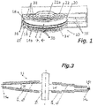
- the figures show variants of an electrical machine in the form of a disc rotor machine 10 .
- This disk rotor machine 10 has a rotor 14 and an at least partially corresponding stator 16.
- the rotor 14 has a carrier disk 14'
- the stator 16 here has two carrier disks 16' aligned axially with the central longitudinal axis of the rotor 14.
- the two carrier discs 16 'of the stand 16 carry in this variant shown each field coil 20, which in connection with the 2 , 2a - 2d are explained in more detail.
- the carrier disks 14' of the rotor 14 carry permanent magnets ⁇ , ⁇ .
- the rotor 14 and the stator 16, more precisely their respective carrier disks 14', 16' each have a mutually facing end face 14a, 14b; 16a, 16b.
- An air gap 18 is formed between the rotor carrier disk 14' and an adjacent stator carrier disk 16'.
- the field coils 20 or the permanent magnets ⁇ , ⁇ are aligned and arranged on the carrier disk 14' of each rotor 14 or the carrier disk 16' of each stator 16 in such a way that the field coils 20 and/or the permanent magnets ⁇ , ⁇ are at least temporarily cause magnetic fields in the same or opposite directions, which cause a rotary or longitudinal relative movement of the rotor 14 to the stator 16.
- the disc rotor machine 10 has iron-containing covers 22 on both of its end faces (top, bottom).
- the ferrous covers 22 are configured as magnetic flux return.
- the carrier disk 14' of each rotor 14 and the carrier disk 16' of each stator 16 are designed as multi-layer circuit boards made of glass fiber reinforced epoxy.
- the field coils 20 are here embedded in the carrier disk 16 ′ of each stator 16 and have a multi-phase configuration and contain copper conductor tracks with vias 20a.
- the space of the rotor 14 and/or the stator 16 located between or in the field coils 20 is ironless.
- Portions of the field coils 20 shown in phantom are embedded in the underside of the support disc 16' of each stator 16, the portions of the field coils 20 illustrated in solid are embedded in the top of the support disc 16' of each stator 16.
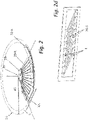
- the individual phases of the field coils 20 of the stator 16 are illustrated.
- the carrier discs 16 'of the stand 16 are omitted for better clarity.
- the course and the relative position of the stator field coils to one another can thus be clearly identified.
- the several phases of the stator field coils are thus aligned, spatially closely packed with the rotor permanent magnets located above/below them (see figure 3 ).
- the machine shaft 26 has a toothed section on which the carrier disks 14' of each rotor 14 are held in a rotationally fixed manner and so as to be movable in the axial direction.
- the stator support disks 16' are fixed against rotation on four pivots on one of the covers 22 and also longitudinally displaceable.
- the rotor carrier disks 14 ′ of the rotor 14 and the stator carrier disks 16 ′ are thus arranged such that they can move in relation to one another in the axial direction along the machine shaft 26 .
- each stand 16 is designed as a circular ring, which in the variant shown lacks a circular segment KA to the full circle.
- the field coils 20 of each stator 16 have radial sections 20-R as well as inner 20-I and Au peripheral sections 20-A, with the outer peripheral sections of the field coils 20 in the area of the missing circular section KA of the annulus having a have higher electrical resistance than the outer-circumferential sections of the field coils 20 in the area without a missing circular section KA of the annulus.
- outer peripheral sections 20-A of the field coils 20 are not raised, as is the case on the rest of the outer circumference of the field coils 20, but are formed from lower, simpler layers because they are still within the trajectory of the runner 16 are.
- the outer-beta peripheral sections 20-A of the field coils 20 in the area without a missing circular section KA of the circular ring are designed as end connectors that are raised in the axial direction compared to the area with a missing circular section KA of the circular ring.
- the outer peripheral portions 20-A of the field coils 20 in the area with no missing circular portion KA of the annulus are formed with multi-layered conductor material, compared to the area with missing circular portion KA with less-layered conductor material.
- the carrier disk of the rotor 16 has a flight circle diameter that at least approximately coincides with the distance AS of a chord S of the missing circular section KA of the annulus from the center Z of the annulus KS of the carrier disk of the stator 18 .
- the circular ring of the carrier disk 14' of each rotor 14 and/or the circular ring of the carrier disk 16' of each stator 16 can also have a polygonal ring shape, deviating from the circular shape shown.
- a plurality of single-phase field coils 20 of the stator 16 are arranged offset to one another along the circumference of the support disk of the stator 16 .
- the outer peripheral sections 20-A of the multiple individual phases of the field coils 20 are arranged here without crossing each other.
- the field coils 20 of the stator 16 can be operated as a Y- or ⁇ -connected arrangement, or can be fed individually. In particular, the spatial arrangement of the field coils 20 to the different poled individual segments of the permanent magnets ⁇ , ⁇ of the rotor 14 the phase association. As in 2 As illustrated, the radial portions 20-R of the field coils 20 of each stator 16 extend substantially between the areas of the inner perimeter portions 20-I to the areas of the outer perimeter portions 20-A.
- a conductor section 20-S is arranged on an outer lateral surface of the carrier disc 16' of the stator 16. This also makes it possible to connect the radial sections 20-R of the field coils 20 on the upper side of the carrier disk 16' of the stator 16 to the radial sections 20-R of the field coils 20 on the underside of the carrier disk 16' of the stator 16 in order to to form the field coils.
- the rotor 14 with the permanent magnets ⁇ , ⁇ has an iron disk 14', on which thin magnetic poles are glued on both sides.
- the thin magnetic poles can be easily magnetized as a whole disc.
- the superimposed magnetic poles are oriented in opposite directions, so that the magnetic flux to the next pole closes between them via the iron disk 14'.
- the electric current directed in the opposite direction produces a torque directed in the same direction of rotation as the electric current on the upper side of the iron disc 14'.
- the conductor sections 20-S acting as end connectors on the outer lateral surface of the carrier disk 16' are preferably short and wide.
- the conductor sections of the multilayer layers forming the field coils are all connected in parallel in each stator 16 .
- the conductor sections 20-S acting as end connectors extend from the field coil sections of a first stator to the field coil sections of a second stator.
- the end connectors 20-S run diagonally here so that the reverse current is routed under the neighboring magnets. Because of the greater distance than with one-sided return (see Figure 2c ) the cross-section of the connector is cheaper.
- the conductor sections of the multilayer layers forming the field coils are all connected in parallel in each stator 16 .
- the vias are also replaced by end connectors in the form of conductor sections 20-S located on the circumference of the stator disk.
- edge connectors are used instead of the vias achieves an improvement in the torque that can be achieved, because the straight, radial conductor sections 20-R reach to the edge of the stator disk.
- the stator 16 has a top and bottom surface with radial conductor sections 20-R for carrying current there and back.
- a in Fig. 2d illustrated forehead connector band is produced in a frame, for example, in etching technology or in laser cutting or stamping technology.
- the end connector band is soldered to the end face of the radial conductor sections 20-R while it is still in the frame.
- the frame is then separated from the end connectors 20-S at the bottlenecks E.
- successive radial sections 20-R of the field coils 20 of the stator 16 are distributed over two carrier disks 16' of the stator 16 which are adjacent in the axial direction and are not shown in this illustration for the sake of clarity.
- Conductor pieces 20-S oriented obliquely on the circumference contact the radial sections 20-R of the field coils 20 of each stator 16 on the respective lateral surfaces of the adjacent carrier disk 16' of the stator 16.
- a special solution for the end connectors is particularly effective on the outer circumference, as there is a torque advantage is usable.
- this connection is only possible radially on the outside because of the shaft.
- the field coils 20 of the stator 16 are formed from a number of individual circuit boards which have copper-containing layers on both sides. In order to obtain a conductor cross-section required for a given current-carrying capacity, a solder layer, a sintered layer and/or copper foil are arranged between two copper-containing layers of adjacent circuit boards.
- two conductors are approximately the same length and a third conductor is arranged between the two conductors of approximately the same length and projects beyond them in the radial direction.
- one of the two conductors of approximately equal length has a cross-connection on one side and the other of the two approximately equal-length conductors has a cross-connection on the other side of the conductor surface.
- the third conductor has a cross-connection on both sides radially on the inside, and the three conductors are electrically contacted with their cross-connections.
- the dimensions and cross-sections of the three conductors and their cross-connections are dimensioned such that the electrical resistances of the respective field coils 20 of the stator 16 are at least approximately the same.
- the three conductors and their interconnections are interconnected by rows or arrays of vias in the manner of open or capped thermal vias.
- the radial sections 20-R of the individual field coils 20 are approximately one- nth the height of the inner and outer peripheral sections 20-I, 20-A. Where n is the number of individual field coils 20 on the carrier disk 16' of the stator 16.
- the electric disk rotor machine is assigned sensor coils of an inductive angle measuring system of the circuit board radially inside the inner peripheral sections 20-I of the individual field coils 20 of the stator 16, on/in/under which the field coils 20 are arranged are. These sensor coils of the inductive angle measuring system are connected to a controller.
- the carrier disk 14' of the rotor 14 is assigned inductive structures which interact with the sensor coils (and are separated by the air gap 18).
- each rotor 14 is formed as a circular ring.
- the permanent magnets ⁇ , ⁇ are at least partially embedded in the carrier disk 14′ of each rotor 14 .
- at least partially embedded, single-phase or multi-phase conductor tracks can also be provided as runner field coils.
- the carrier disc 14' of each rotor 14 has an axial height near the center which is higher than at the outer edge of the carrier disc.
- the permanent magnets ⁇ , ⁇ or rotor field coils are at least partially embedded in the carrier disk 14′ of each rotor 14 in such a way that the axial height of the circular ring is higher near the center of the carrier disk than at the outer edge of the carrier disk.
- the angle W which the upper and the lower surface of the carrier disc 14' of the rotor 14 enclose, is between 3° and 30°.
- a variant is shown on the left side of the figure, in which the change in the axial height in the radial direction is concentrically stepless, while in 3 on the right side of the figure a variant not belonging to the invention is shown, in which the variation of the axial height is graduated in the radial direction.
- the rotor 14 has a disk made of steel, which is connected to the machine shaft 26 in a torque-proof manner.
- the steel disk carries the permanent magnets ⁇ , ⁇ on at least one of its two sides, which are preferably designed as cylinder or cone ring segments. Rotor field coils can also be provided instead of the magnets.
- Permanent magnets arranged on both sides of the disc of the rotor 14 and aligned with one another in the axial direction each have the same or opposite magnetic orientation.
- oppositely oriented permanent magnets are arranged on the disc of the rotor 14 on both sides.
- the disc 14' of the rotor 14 is designed in one piece with the machine shaft in a variant which does not belong to the invention.
- the permanent magnets arranged on both sides are designed as thin magnetic disks, and the axial height of the carrier disk of rotor 14 decreasing towards the outer edge is essentially achieved by decreasing thickness of the disk of rotor 14 with essentially the same thickness of the permanent magnets.
- the disc of the rotor 14 has an annular sliding bearing 14a on the outer circumference.
- a groove is machined into the outer edge of the disc, into which several sliding pieces 14b, which are fixed to the housing and distributed around the circumference, engage.
- the carrier disk 16' of the stator 16 and ferromagnetic yoke parts 22 and a housing are divided into two (or more) parts in the axial direction (or at an angle to the longitudinal center axis of the disk rotor machine).
- the individual parts of the carrier disc 16 ′ and the return path parts are introduced into the respective housing parts with a positive and/or material connection.
- In 1 is further illustrated how two support disks of the stator 16 receive a disk of the rotor 14 between them in the axial direction.
- the two carrier disks of the stator 16 are mounted so that they can move in the axial direction together with their respective ferromagnetic yoke 22 .
- the stator coils are energized during operation, the two carrier disks of the stator 16 are attracted to the disk of the rotor 14 .
- At least one draw/hold coil 38 is arranged on both sides of the disk of the rotor 14 in the ferromagnetic yokes 22 or the housing 36 of the disk rotor machine.
- these pull/hold coils 38 are energized accordingly, they act together with the ferromagnetic yokes 22 or the housing 36 pull/hold coils 38 and the ferromagnetic yokes 22 or the housing 36 like lifting magnets and pull the two carrier disks of the stator 16 from the disk of the runner 14 at a distance and hold it in this position. Since the machine is usually only in operation for a short time, the operation of the lifting magnets does not represent an excessive load.
- the permanent magnets ⁇ , ⁇ of the rotor 14 and the coils 20 of the stator 16 are separated from one another by an insulating layer. Furthermore, each of the discs of the stator 16, the ferromagnetic yokes 22 and the disc of the rotor 14 are axially supported and provided with stops relative to one another so that each of the discs of the stator 16 is attracted to the corresponding one of the ferromagnetic yokes 22 in the attracted state abuts, and each of the discs of the stand 16 opposite of the disk of the rotor 14 maintains an air gap of approximately 0.1 mm to approximately 0.3 mm during operation.
- Permanent magnets ⁇ , ⁇ are embedded or at least partially exposed permanent magnets ⁇ , ⁇ are provided in the carrier disk 14′ of each rotor 14 or each stator 16, which are approximately 0.5 to 3 times, preferably one to twice as high in the axial direction the air gap is 18.
- the permanent magnets ⁇ , ⁇ are preferably side earth magnets.
- the stator 16 has three-phase or higher-phase stator coils 20.
- a rotor bearing disk is connected to a housing, or the rotor bearing disk forms at least one section of the housing.
Description
Hier wird eine elektrische Scheibenläufermaschine beschrieben, die zum Beispiel für einen Einsatz in einem Fahrzeug, als Antrieb in einem Roboterarm oder zur Positionierung z.B. von Maschinenteilen und dergl. mehr geeignet und vorgesehen ist. Dabei kann es sich auch um eine elektrische Maschine handeln, die als Hilfs- oder Nebenaggregat in dem Fahrzeug oder Fluggerät geeignet und vorgesehen ist.Here, an electric disc rotor machine is described which is more suitable and intended for use in a vehicle, as a drive in a robot arm or for positioning machine parts and the like, for example. This can also be an electrical machine that is suitable and provided as an auxiliary or ancillary unit in the vehicle or aircraft.
Elektrische Maschinen werden in einer Vielzahl von Industrie-, Mobilitäts- und Komfort- / Sicherheitsanwendungen eingesetzt. Dabei besteht oft die Anforderung nach einer kompakten, leichtgewichtigen Maschine die mit minimaler Verzögerung eine Drehbewegung von wenigen hundert Grad bis zu mehreren (etwa zehn) Vollumdrehungen mit hohem Drehmoment ausführt. Eine weitere Forderung besteht nach guter Eignung zum Betrieb der Maschine mit einem mehrphasigen leistungselektronischen Stellglied (Umrichter oder Wechselrichter). Bisher sind Scheibenläufer, insbesondere Permanentmagnet-Maschinen, meist in Spezialanwendungen wie getriebelosen, langsam laufenden Drehmomentmaschinen anzutreffen. Außerdem werden Scheibenläufermaschinen vor allem eingesetzt, wenn ein kleines Längen-Durchmesser-Verhältnis gefordert ist.Electric machines are used in a variety of industrial, mobility, and comfort/safety applications. There is often a requirement for a compact, lightweight machine that can perform a rotary movement of a few hundred degrees to several (about ten) full revolutions with minimal delay with high torque. Another requirement is good suitability for operating the machine with a multi-phase power electronic actuator (converter or inverter). Until now, disk rotors, especially permanent magnet machines, have mostly been found in special applications such as gearless, low-speed torque machines. In addition, disc rotor machines are primarily used when a small length-diameter ratio is required.
Das Dokument
Ferner offenbaren auch die Dokumente
Die zu lösende Aufgabe ist, eine elektrische Maschine bereitzustellen, die in kleinem Bauraum einen effizienten, sicheren Betrieb erlaubt.The task to be solved is to provide an electrical machine that allows efficient, safe operation in a small space.
Das obige zugrundeliegende Problem ist, erfindungsgemäß, durch die unabhängige Ansprüche 1 und 3 gelöst. Ein Verfahren zur Herstellung einer Scheibenläufermaschine nach einem der Ansprüche 1 oder 3 ist im Anspruch 12 gegeben. Verschiedene Ausgestaltungen und Varianten gemäß der Erfindung sind in den Nebenansprüchen gegeben.The above underlying problem is solved by independent claims 1 and 3 according to the invention. A method for manufacturing a disc machine according to one of claims 1 or 3 is given in claim 12. Different developments and variants according to the invention are given in the subclaims.
Insbesondere bei räumlich beengten Anwendungen, in denen die Maschine in ein im Querschnitt mehr-, zum Beispiel viereckiges Profil einzubauen ist, kann mit dieser Ausgestaltung eine nennenswert höhere Leistung erzielt werden, als mit einer im Querschnitt kreisrund gestalteten Maschine, deren Außenumfang den Inkreis des mehreckigen Profil bildet. Im Übrigen erlaubt diese Maschine einen Kurzzeitbetrieb mit Anlaufzeiten im Millisekundenbereich bei sehr hoher Beschleunigung und einer sehr hohen Drehmomentdichte aufgrund des geringen benötigten Bauraums. Diese hier beschriebenen Scheibenläufermaschinen sind sehr geräuscharm und funktionssicher, da sie kein Getriebe benötigen. Außerdem erlauben sie eine einfache Drehwinkel- oder Wegerfassung in der Maschine; ihre Drehzahl / ihr Weg lässt sich sehr effizient regeln. Da sich zwischen den Spulen / Permanentmagneten vorzugsweise kein Eisen befindet, ist ein maximaler Kupfereinsatz zur Minimierung der ohmschen Verluste möglich; außerdem gibt es keine Platzkonkurrenz zwischen einem Eisenkreis und den Feldspulen. Des Weiteren ist keine Begrenzung der Ströme durch Eisensättigung möglich; es gibt nur die Superposition der magnetischen Felder. Anfallende Verlustleistung kann während der kurzen Betriebsdauer in den Leitern der Feldspulen aufgenommen und in der anschließenden Ruhephase abgegeben werden; somit ist keine externe Kühlung erforderlich. Ein Vorteil der hier beschriebenen Scheibenläufermaschinen ist auch die Eignung zum mehrfachen Überlastbetrieb in sehr geringen zeitlichen Abständen.Especially in applications where space is limited, in which the machine is to be installed in a profile with a polygonal cross section, e.g. a square section, a significantly higher output can be achieved with this design than with a machine with a circular cross section, the outer circumference of which corresponds to the inscribed circle of the polygonal profile. In addition, this machine allows short-term operation with start-up times in the millisecond range with very high acceleration and a very high torque density due to the small installation space required. The disc rotor machines described here are very quiet and reliable because they do not require a gear. In addition, they allow a simple measurement of the angle of rotation or displacement in the machine; their speed / their path can be controlled very efficiently. Since there is preferably no iron between the coils/permanent magnets, maximum use of copper is possible to minimize ohmic losses; moreover, there is no competition for space between an iron circuit and the field coils. Furthermore, the currents cannot be limited by iron saturation; there is only the superposition of the magnetic fields. Any power loss that occurs can be absorbed in the conductors of the field coils during the short period of operation and released in the subsequent idle phase; thus no external cooling is required. An advantage of the disc rotor machines described here is their suitability for multiple overload operation at very short time intervals.
Der Läufer kann eine Trägerscheibe aus Eisen haben, die in der axialen Magnetmitte auch dick sein kann, sofern sie magnetisierbar ist. Wenn sie an der Ober- und Unterseite liegt, sollte sie dünn sein, damit sie, wenn sie magnetisierbar ist, die Magnetpole nicht kurzschließt. Unmagnetischer Stahl würde nur den Luftspalt vergrößern, was unerwünscht ist.The rotor can have an iron carrier disk, which can also be thick in the axial center of the magnet, provided it can be magnetized. If it's on the top and bottom, it should be thin so that if it's magnetizable, it doesn't short out the magnetic poles. Non-magnetic steel would only increase the air gap, which is undesirable.
Unter "zwischen den Spulen / Permanentmagneten befindet sich vorzugsweise kein Eisen" sei verstanden, dass ein dünnes, magnetisierbares Stahlblech an einer oder beiden Oberflächen der Ständer- oder Läuferscheibe zum Beispiel als Gleitlager oder als Träger durchaus möglich ist.“Preferably there is no iron between the coils/permanent magnets” means that a thin, magnetizable sheet steel is entirely possible on one or both surfaces of the stator or rotor disk, for example as a plain bearing or as a carrier.
Die folgenden Ausgestaltungen und Varianten gehören zur Erfindung, sofern nicht ausdrücklich anderes angegeben.The following configurations and variants are part of the invention, unless expressly stated otherwise.
Die hier beschriebenen Scheibenläufermaschinen können entweder als Innen- oder als Au-ßenläufermaschinen realisiert sein. Diese Scheibenläufermaschinen können sowohl als elektrischer Motor als auch als elektrischer Generator betrieben werden. Sie kommen insbesondere als Drehmaschine zum Einsatz; aber auch eine Implementierung als Linearmaschine ist in einigen Varianten möglich. Die Scheibenläufermaschinen der hier beschriebenen Art können entweder fremd- oder selbsterregt ausgestaltet sein. Bei fremderregten Maschinen sind eine oder mehrere Erregerwicklungen für die Erregung vorgesehen. Die Erregerwicklung wird zum Beispiel durch eine gesteuerte Stromquelle mit Energie gespeist. Bei einer selbsterregten Scheibenläufermaschine treten Permanentmagnete an die Stelle der Erregerwicklungen.The disk rotor machines described here can be implemented either as internal or external rotor machines. These disk rotor machines can be operated both as an electric motor and as an electric generator. They are used in particular as lathes; but implementation as a linear machine is also possible in some variants. The disc rotor machines of the type described here can either be externally or self-excited. In the case of separately excited machines, one or more excitation windings are provided for excitation. The excitation winding is energized by, for example, a controlled current source. In a self-excited disc rotor machine, permanent magnets take the place of the excitation windings.
Eine fremd- oder selbsterregte Scheibenläufermaschine kann als permanent erregte Maschine ausgestaltet sein. Schleifringe zum Speisung mit elektrischer Leistung und Ankerwicklung (en) können dabei als gedruckte Schaltung auf einer dünnen Kunststoff- oder Keramikscheibe realisiert sein. Der elektrische Strom wird im einfachsten Fall über Kohlebürsten direkt auf die die Schleifringe an der Scheibe zugeführt. Die Scheibe trägt somit die Schleifringe und die Läufer-Wicklung(en) und läuft in einem engen Luftspalt zwischen Ständerspulen oder Permanentmagneten. Zur Sicherstellung der mechanischen Funktion können auch Gleitfolien in den/ die Luftspalt/e zwischen die Scheibe/n und Ständerspulen oder Permanentmagnete/n angeordnet sein.An externally or self-excited disc rotor machine can be designed as a permanently excited machine. Slip rings for supplying electrical power and armature winding(s) can be implemented as a printed circuit on a thin plastic or ceramic disc. In the simplest case, the electrical current is fed directly to the slip rings on the disc via carbon brushes. The disk thus carries the slip rings and the rotor winding(s) and runs in a narrow air gap between stator coils or permanent magnets. To ensure the mechanical function, sliding foils can also be arranged in the air gap(s) between the disk(s) and stator coil(s) or permanent magnet(s).
Ein selbsterregter oder permanenterregter Läufer kann eine weichmagnetische Trägerscheibe, zum Beispiel aus weichmagnetischem Stahl haben, an der beidseitig in axialer orientierte Magnetscheibensegmente z.B. aus Ferrit oder kunststoffgebundenem NdFeB angebracht sind. Alternativ dazu kann der selbsterregte oder permanenterregte Läufer als durchgehende Magnetscheibe realisiert sein, die polweise axial alternierend orientiert magnetisiert ist.A self-excited or permanently excited rotor can have a soft-magnetic carrier disk, e.g. made of soft-magnetic steel, to which axially oriented magnetic disk segments, e.g. made of ferrite or plastic-bonded NdFeB, are attached on both sides. As an alternative to this, the self-excited or permanently excited rotor can be implemented as a continuous magnetic disc which is magnetized pole-by-pole with an axially alternating orientation.
Für größere Leistungsdichten wird die hier vorgestellte Scheibenläufermaschine als Doppelscheibenläufer mit Zwischenständer ausgeführt, der z.B. mit Seltenerden-Magnetsegmenten oder entsprechenden Ständerwicklungen versehen und. So entfallen die bei einer Einscheibenläuferausführung auftretenden axialen Zugkräfte. Letztere können auftreten, wenn auf einer Seite kein Ständer mit Rückschlussscheibe angeordnet istFor higher power densities, the disc rotor machine presented here is designed as a double disc rotor with an intermediate stator, which is provided with rare-earth magnet segments or corresponding stator windings, for example. This eliminates the axial tensile forces that occur with a single-disc rotor design. The latter can occur if there is no stand with a return disc on one side
Scheibenläufermaschinen der hier vorgestellten Art haben durch ihre praktisch eisenfreien Läufer eine hohe Dynamik bei einem geringen Gewicht. Die Läufer sind entweder Anordnungen von (Selten-Erden-)Permamentmagnetelementen oder haben geeignet gestaltete Feldspulen. Das den Scheibenläufermaschinen zugrundeliegende physikalische Prinzip führt zu einem direkt proportionalen Verhältnis zwischen Spannung und Drehzahl sowie Strom und Drehmoment.Disk rotor machines of the type presented here have high dynamics and low weight thanks to their practically iron-free rotors. The runners are either arrays of (rare earth) permanent magnet elements or have suitably designed field coils. The physical principle on which disc motors are based leads to a directly proportional relationship between voltage and speed as well as current and torque.
Unter "praktisch eisenfrei" sei verstanden, dass auch Varianten mit einer Eisenscheibe in der axial gesehenen Magnetmitte umfasst sind.“Practically iron-free” is understood to mean that variants with an iron disc in the axial center of the magnet are also included.
Da die Ständer- (und ggf. Läufer-)Spulen bei den meisten Varianten praktisch eisenfrei sind, entfallen auch etwaige Eisenverluste. Auch die Spuleninduktivität kann nennenswert reduziert sein. Die Läufermasse und damit deren translatorisches und rotatorisches Trägheitsmoment sind ebenfalls reduziert. Die Maschinen haben eine geringe Störabstrahlung, eine hohe elektromagnetische Verträglichkeit (EMV), und sie haben keine Reluktanzmomente.Since the stator (and possibly rotor) coils are practically iron-free in most variants, there are also no iron losses. The coil inductance can also be significantly reduced. The rotor mass and thus its translational and rotational moment of inertia are also reduced. The machines have low interference emissions, high electromagnetic compatibility (EMC), and they have no reluctance torques.
Schließlich haben die Scheibenläufermaschinen eine geringe axiale Länge. Im Ständer auftretende Verlustwärme kann ebenfalls relativ einfach nach außen abgeführt werden, wegen der flächigen Anbindung des Stators an die Rückschluss-Scheibe, zumindest bei Einscheibenläufern. Die nennenswert reduzierte Spuleninduktivität führt zu einer geringeren Leistungsinstallation des Wechselrichters.Finally, the disc rotor machines have a small axial length. Heat loss that occurs in the stator can also be dissipated to the outside relatively easily, because of the surface connection of the stator to the return disc, at least in the case of single-disc rotors. The significantly reduced coil inductance leads to a lower power installation of the inverter.
Eisenverluste können im magnetischen Rückschluss auftreten, dieser ist deshalb vorzugsweise aus Pulvereisen hergestellt.Iron losses can occur in the magnetic yoke, which is why it is preferably made of powdered iron.
Die Läufer- und/oder Ständer-Wicklungen können als gedruckte, gestanzte oder geätzte Leiterbahnen auf/in ein- oder mehrlagigen Leiterplatten realisiert sein. Auch die Einbettung von vorgefertigten Luftspulen aus (Kupfer-, Aluminium- oder dergl.) Draht- oder Blechmaterial in (faserverstärktes) -Kunststoffmaterial (Epoxy, Keramik, PTFE, Polyimid) ist vorgesehen. Die Ständer- und Läuferscheiben mit den Spulen können mittels reibungserhöhenden oder reibungsverringernden, isolierenden Beschichtungen versehen sein.The rotor and/or stator windings can be implemented as printed, stamped or etched conductor tracks on/in single-layer or multi-layer printed circuit boards. The embedding of prefabricated air-core coils made of (copper, aluminum or similar) wire or sheet material in (fibre-reinforced) plastic material (epoxy, ceramic, PTFE, polyimide) is also provided. The stator and rotor disks with the coils can be provided with friction-increasing or friction-reducing insulating coatings.
Durch den Aufbau der Ständer-Feldspulen als Multilayerplatinen ist ein hoher Kupferfüllfaktor bei großer mechanischer Festigkeit möglich; Die erforderliche Windungszahl kann durch Implementierung der Feldspulen in mehreren Multilayerlagen realisiert werden. Die Abstände der Leiterbahnen können auf die doppelte Leiterbahndicke begrenzt sein; dies reduziert den Totraum auf und in den Trägerscheiben. Im Übrigen kann der mehrlagige Spulenaufbau mittels Durchkontaktierungen in Form von vias realisiert sein. Zusätzliche Wärmekapazität in den Trägerscheiben kann durch dünne Alu-, Kupfer- oder Prepreglagen realisiert sein. Statt Metalleinlagen kann auch der Leiterquerschnitt mittels der Alu- oder Kupferlagen vergrößert werden, da dann die Wärmekapazität ebenso vergrößert wird und gleichzeitig die Verluste sinken. Die zum Aufbau der Spule erforderlichen Prepregs tragen nennenswert zur Wärmekapazität bei, da die spezifische Wärme von Kunststoffen im Vergleich zu Metallen hoch ist. Die Außen-Umfangs-Abschnitte der Feldspulen sind in einer Variante im Bereich ohne fehlenden Kreisabschnitt des Kreisrings als in axialer Richtung erhöhte Stirnverbinder gegenüber dem Bereich mit fehlendem Kreisabschnitt des Kreisrings ausgebildet.Due to the construction of the stator field coils as multilayer circuit boards, a high copper fill factor with high mechanical strength is possible; The required number of turns can be realized by implementing the field coils in several multilayer layers. The spacing of the traces can be limited to twice the thickness of the trace; this reduces the Dead space on and in the carrier discs. In addition, the multi-layer coil structure can be realized by means of plated-through holes in the form of vias. Additional heat capacity in the carrier disks can be realized by thin aluminum, copper or prepreg layers. Instead of metal inserts, the conductor cross-section can also be increased using aluminum or copper layers, since the heat capacity is then also increased and losses are reduced at the same time. The prepregs required to build the coil contribute significantly to the heat capacity, as the specific heat of plastics is high compared to metals. In one variant, the outer-circumferential sections of the field coils in the area without a missing circular section of the circular ring are designed as end connectors that are raised in the axial direction compared to the area with a missing circular section of the circular ring.
Die Außen-Umfangs-Abschnitte der Feldspulen im Bereich ohne fehlenden Kreisabschnitt des Kreisrings sind in einer Variante als mehrlagiges Leitermaterial gegenüber dem Bereich mit fehlendem Kreisabschnitt mit weniger lagigem Leitermaterial ausgebildet.In one variant, the outer peripheral sections of the field coils in the area without a missing circular section of the annulus are designed as a multi-layer conductor material, compared to the area with a missing circular section with less layered conductor material.
Die Trägerscheibe des Läufers hat in einer Variante einen Flugkreis-Durchmesser, der mit dem Abstand einer Sehne des fehlenden Kreisabschnitts des Kreisrings vom Zentrum des Kreisrings der Trägerscheibe des Ständers zumindest annähernd zusammenfällt.In one variant, the carrier disk of the rotor has a flight circle diameter which at least approximately coincides with the distance of a chord of the missing circular section of the annulus from the center of the annulus of the carrier disk of the stator.
Der Kreisring der Trägerscheibe jedes Läufers und/oder der Kreisring der Trägerscheibe jedes Ständers haben in einer Variante jeweils eine Polygonringform (4 - 12 oder mehr-Eck).In one variant, the circular ring of the carrier disk of each rotor and/or the circular ring of the carrier disk of each stator each have a polygonal ring shape (4-12 or more corners).
Erfindungsgemäß wird eine elektrische Scheibenläufermaschine mit wenigstens einem Läufer und wenigstens einem zu dem Läufer zumindest teilweise korrespondierenden Ständer vorgestellt. Der wenigstens eine Läufer und der wenigstens eine Ständer haben jeweils eine einander zugewandte Stirnseite. Der wenigstens eine Läufer Feldspulen oder Permanentmagnete trägt und der wenigstensAccording to the invention, an electric disc rotor machine is presented with at least one rotor and at least one stator that at least partially corresponds to the rotor. The at least one rotor and the at least one stator each have an end face facing one another. The at least one runner carries field coils or permanent magnets and the at least
eine Ständer Feldspulen trägt. Zwischen jedem Läufer und jedem Ständer ist jeweils ein Luftspalt ausgebildet. Die Feldspulen und/oder die Permanentmagnete sind derart ausgerichtet und an jedem Läufer bzw. jedem Ständer angeordnet, dass die Feldspulen im stromdurchflossenen Zustand und/oder die Permanentmagnete zumindest zeitweilig gleich- oder gegensinnige Magnetfelder hervorrufen, die eine Dreh- oder Längs-Relativbewegung des Läufers zum Ständer bewirken. Jedes Läufer ist als Kreisring ausgebildet, und in jeden Läufer sind die Permanentmagnete zumindest teilweise eingebettet, oder sind zumindest teilweise eingebettete, ein- oder mehrphasig ausgestaltete Leiterbahnzüge als Feldspulen vorgesehen. Mehrere einphasige Feldspulen des Ständers sind entlang des Umfangs des Ständers versetzt zueinander angeordnet, wobei die Feldspulen jedes Ständers Radial-Abschnitte, d.h. sich radial erstreckende Abschnitte, sowie Innen- und Außen-Umfangs-Abschnitte, d.h. sich in Innen- und Außen-Umfangsrichtung erstreckende Abschnitte, aufweisen. Die Außen-Umfangs-Abschnitte der mehreren einphasigen Feldspulen sind überkreuzungsfrei zueinander angeordnet, wobei die sich radial erstreckenden Abschnitte in axialer Richtung etwa ein n-tel der Höhe der sich in Innen- und Außen-Umfangsrichtung erstreckenden Abschnitte aufweisen, wobei n die Anzahl der einphasigen Feldspulen (20) auf der Trägerscheibe des Ständers (16) ist.a stand carries field coils. An air gap is formed between each rotor and each stator. The field coils and/or the permanent magnets are aligned and arranged on each rotor or each stator in such a way that the field coils, when current is flowing through them, and/or the permanent magnets at least temporarily produce magnetic fields in the same or opposite directions, which cause a rotary or longitudinal relative movement of the rotor cause to the stand. Each runner is designed as a circular ring, and the permanent magnets are at least partially embedded in each runner, or are at least partially embedded and configured with one or more phases Conductor tracks provided as field coils. Several single-phase field coils of the stator are staggered along the circumference of the stator, the Field coils of each stator have radial sections, ie, radially extending sections, and inner and outer circumferential sections, ie, inner and outer circumferentially extending sections. The outer-circumferential portions of the plurality of single-phase field coils are arranged without crossing each other, with the radially-extending portions in the axial direction being about one-nth the height of the inner- and outer-circumferential extending portions, where n is the number of single-phase Field coils (20) on the carrier disc of the stator (16).
Da die Stirnverbinder keine Überkreuzungen haben, sind sie bei gleicher Polteilung breiter, da zwei von drei Abständen zwischen den einzelnen Leitern wegfallen. Dies hat einen geringeren elektrischen Widerstand zur Folge und benötigt in nur eine reduzierte Wechselrichterleistung. Die kurzen Verbinder mit großem Querschnitt und geringem Widerstand und einen bis zum radial äußeren/inneren Rand gehenden kraftbildenden Leiter der Ständer-Feldspulen vermeiden Krafteinbußen durch Fehllagen der Ströme im Wickelkopf. Die Leiter der Ständer-Feldspulen sind bei großen Radien sind besonders effektiv, da hier Querschnitt und Hebelarm am größten sind.Since the end connectors do not have any crossovers, they are wider with the same pole pitch, since two of the three distances between the individual conductors are eliminated. This results in lower electrical resistance and only requires reduced inverter power. The short connectors with a large cross-section and low resistance and a force-forming conductor of the stator field coils that extends to the radial outer/inner edge prevent power losses due to misalignment of the currents in the winding overhang. The conductors of the stator field coils are particularly effective with large radii, since the cross-section and lever arm are greatest here.
Die Aufteilung auf mehrere bzw. höherphasige Systeme erlaubt geringere Leistung der einzelnen Halbleiter-Schalter in der Ansteuerelektronik (Wechselrichter) und geringere Rückwirkungen auf den Zwischenkreis. Dies gilt insbesondere für zwei oder drei versetzt taktende dreiphasige Systeme. Auch Geräuschvorteile sind durch eine höherfrequente Anregung erzielbar. Bei höherphasigen Systemen fällt der durch den Phasenversatz hervorgerufene Drehmomentverlust geringer aus.The division into several or higher-phase systems allows lower performance of the individual semiconductor switches in the control electronics (inverter) and lower repercussions on the intermediate circuit. This applies in particular to two or three staggered three-phase systems. Noise benefits can also be achieved through higher-frequency excitation. With higher-phase systems, the torque loss caused by the phase shift is lower.
In einer Variante sind die Feldspulen des Ständers Y-oder Δ-verschaltete Anordnungen, oder sie sind einzeln gespeist. Dabei bestimmt sich insbesondere die räumliche Anordnung der Feldspulen zu den Permanentmagneten des Läufers durch die Phasenzugehörigkeit.In a variant, the field coils of the stator are Y-connected or Δ-connected arrangements, or they are fed individually. In particular, the spatial arrangement of the field coils with respect to the permanent magnets of the rotor is determined by the phase relationship.
Die Radial-Abschnitte der Feldspulen jedes Ständers verlaufen gerade bis zu einem Bereich der Außen-Umfangs-Abschnitte.The radial sections of the field coils of each stator extend straight to a portion of the outer perimeter sections.
Als Stirnverbinder ist in einer Variante ein Leiterabschnitt an einer äußeren Mantelfläche der Trägerscheibe des Ständers angeordnet. Dabei können die äußeren Stirnverbinder über stirnseitige Kantenmetallisierung angelötet sein.As a forehead connector is a conductor section on an outer surface of the in a variant Arranged carrier disc of the stand. In this case, the outer end connectors can be soldered on by means of edge metallization on the end face.
Aufeinander folgende Radial-Abschnitte der Feldspulen des Ständers sind in einer Variante auf zwei in axialer Richtung benachbarte Trägerscheiben des Ständers verteilt, wobei Leiter an jeweiligen Mantelflächen der benachbarten Trägerscheibe des Ständers die Radial-Abschnitte der Feldspulen jedes Ständers kontaktieren.In one variant, successive radial sections of the field coils of the stator are distributed over two axially adjacent support disks of the stator, with conductors on respective lateral surfaces of the adjacent support disk of the stator contacting the radial sections of the field coils of each stator.
Die Feldspulen des Ständers sind in einer Variante aus mehreren einzelnen Platinen gebildet, die beidseitig kupferhaltige Schichten aufweisen, wobei zwischen zwei kupferhaltigen Schichten benachbarter Platinen eine Lotschicht, eine Sinterschicht oder der Form der Feldspule entsprechende Kupferfolie angeordnet ist. Damit kann bei schmalen Leitern ein nennenswerter Widerstandsvorteil erreicht werden.In one variant, the field coils of the stator are formed from several individual circuit boards which have layers containing copper on both sides, with a layer of solder, a sintered layer or copper foil corresponding to the shape of the field coil being arranged between two layers containing copper on adjacent circuit boards. This means that a significant advantage in resistance can be achieved with narrow conductors.
Als Stirnverbinder sind in einer Variante an einem inneren Rand der Trägerscheibe des Ständers zwei Leiter etwa gleich lang und ein dritter Leiter ist zwischen den beiden etwa gleich langen Leitern angeordnet und überragt diese in radialer Richtung nach innen. Als Stirnverbinder ist bei dem einen der beiden etwa gleich langen Leiter eine Querverbindung an der einen Seite, und bei dem anderen der beiden etwa gleich langen Leiter eine Querverbindung an der anderen Seite der Leiteroberfläche angeordnet, und der dritte Leiter hat radial innenliegend an beiden Seiten jeweils eine Querverbindung. Die drei Leiter sind mit ihren Querverbindungen elektrisch kontaktiert.In one variant, two conductors of approximately the same length are used as end connectors on an inner edge of the support disk of the stator, and a third conductor is arranged between the two conductors of approximately the same length and protrudes inwards in the radial direction. As an end connector, one of the two conductors of approximately the same length has a cross-connection on one side, and the other of the two conductors of approximately the same length has a cross-connection on the other side of the conductor surface, and the third conductor has a radially inward position on both sides a cross connection. The three conductors are electrically contacted with their cross-connections.
Die drei Leiter und ihre Querverbindungen sind hinsichtlich ihrer Abmessungen und Querschnitte so dimensioniert, dass die elektrischen Widerstände der jeweiligen Feldspulen des Ständers zumindest annähernd übereinstimmen.The dimensions and cross-sections of the three conductors and their cross-connections are dimensioned such that the electrical resistances of the respective field coils of the stator are at least approximately the same.
Dabei können die drei Leiter und ihre Querverbindungen mittels Reihen oder Feldern von Durchkontaktierungen nach Art offener oder gedeckelter thermal Vias miteinander verbunden sein.In this case, the three conductors and their cross-connections can be connected to one another by means of rows or arrays of vias in the manner of open or capped thermal vias.
Sensorspulen eines induktiven Winkelmessystems sind in einer Variante , die nicht zur Erfindung gehört, radial innerhalb derSensor coils of an inductive angle measuring system are in a variant that does not belong to the invention, radially inside
Innen-Umfangs-Abschnitte des Ständers der Platine zugeordnet und mit einer Steuerung verbunden. Dabei sind der Trägerscheibe des Läufers mit den Sensorspulen zusammenwirkende induktive Strukturen zugeordnet. Dies ist eine sehr robuste, kostengünstige Anordnung mit schneller Rückmeldung über die die Winkellage, die auch unempfindlich gegen Verschmutzung aller Art sowie elektromagnetische Störungen ist.Inner perimeter portions of the stand associated with the circuit board and connected to a controller. In this case, inductive structures which interact with the sensor coils are assigned to the carrier disk of the rotor. This is a very robust, cost-effective arrangement with fast feedback on the angular position, which is also insensitive to dirt of all kinds and electromagnetic interference.
Gemäß einem weiteren Aspekt , der nicht zur Erfindung gehört, der elektrischen Scheibenläufermaschine ist diese mit wenigstens einem Läufer und wenigstens einem zu dem Läufer zumindest teilweise korrespondierenden Ständer ausgestattet. Dabei haben der wenigstens eine Läufer und der wenigstens eine Ständer jeweils eine einander zugewandte Stirnseite. Der wenigstens eine Läufer und der wenigstens eine Ständer tragen jeweils Feldspulen oder Permanentmagnete tragen. Zwischen jedem Läufer und jedem Ständer ist jeweils ein Luftspalt ausgebildet. Die Feldspulen und/oder die Permanentmagnete sind derart ausgerichtet und an jedem Läufer bzw. jedem Ständer so angeordnet sind, dass die Feldspulen im stromdurchflossenen Zustand und/oder die Permanentmagnete zumindest zeitweilig gleich- oder gegensinnige Magnetfelder hervorrufen, die eine Dreh- oder Längs-Relativbewegung des Läufers zum Ständer bewirken. Jeder Läufer ist als Kreisring ausgebildet. In jeden Läufer sind die Permanentmagnete zumindest teilweise eingebettet, oder zumindest teilweise eingebettete, ein- oder mehrphasig ausgestaltete Leiterbahnzüge sind als Feldspulen vorgesehen. Jeder Läufer hat eine axiale Höhe nahe dem Zentrum / der Mittellängsachse der Scheibenläufermaschine, die höher ist als am äußeren Rand des jeweiligen Läufers. In jeden Läufers sind die Permanentmagnete / Feldspulen zumindest teilweise so eingebettet, dass die axiale Höhe nahe dem Zentrum des Kreisrings höher ist als am äußeren Rand des Läufers, wobei die Änderung der axialen Höhe in radialer Richtung konzentrisch stufenlos oder gestuft ist.According to a further aspect which does not belong to the invention, the electric disk rotor machine is provided with at least one rotor and at least one rotor at least partially corresponding to the rotor stand equipped. The at least one runner and the at least a stand in each case a mutually facing end face. The at least one rotor and the at least one stator each carry field coils or permanent magnets. An air gap is formed between each rotor and each stator. The field coils and/or the permanent magnets are aligned and arranged on each rotor or each stator in such a way that the field coils and/or the permanent magnets, when current is flowing through them, at least temporarily produce magnetic fields in the same or opposite directions, which cause a rotary or longitudinal relative movement of the rotor to the stator. Each runner is designed as a circular ring. The permanent magnets are at least partially embedded in each rotor, or at least partially embedded, single-phase or multi-phase conductor tracks are provided as field coils. Each rotor has an axial height near the center/central longitudinal axis of the disk rotor machine that is higher than at the outer edge of the respective rotor. In each rotor, the permanent magnets/field coils are at least partially embedded in such a way that the axial height near the center of the annulus is higher than at the outer edge of the rotor, with the change in axial height in the radial direction being concentrically stepless or stepped.
Der die Permanentmagnete tragende Läufer kann in radialer Richtung mit mehreren Magnetringen ausgeführt sein. Die Multilayerplatine wird zum Zentrum hin dicker und vermeidet damit einen Widerstandsanstieg im Innenbereich. Die axiale Höhe der Magnetringe kann nach innen hin zur Optimierung des Wirkungsgrades zunehmen. Entsprechend der geringeren Verlustleistung kann der Wechselrichter und die Stromversorgung schwächer ausgeführt werden.The rotor carrying the permanent magnets can be designed with several magnet rings in the radial direction. The multilayer board gets thicker towards the center and thus avoids an increase in resistance in the inner area. The axial height of the magnetic rings can increase towards the inside in order to optimize efficiency. According to the lower power loss, the inverter and the power supply can be made weaker.
Der Läufer hat in einer Variante , die nicht zur Erfindung gehört, eine Scheibe aus Stahl, die mit einer Maschinenwelle drehfest und ggf. längsverschieblich verbunden ist. An wenigsten einer ihrer beiden Seiten trägt die Scheibe des Läufers vorzugsweise als Zylinder- oder Kegel-Ringsegmente gestaltete Permanentmagnete. Eine Stahlscheibe mitten im Läufer gepaart mit gleichsinnig orientierten Permanentmagneten ergibt einen stabileren Aufbau. Gegensinnig orientierte Permanentmagnete erlauben zusätzlich eine Leitungs-Rückführung ohne Überkreuzung auf einer zweiten Scheibe, wenn auch zu Lasten eines höheren Trägheitsmomentes.In a variant which does not belong to the invention, the runner has a disk made of steel which is connected to a machine shaft in a rotationally fixed manner and, if necessary, in a longitudinally displaceable manner. On at least one of its two sides, the disk of the rotor carries permanent magnets, preferably designed as cylindrical or conical ring segments. A steel disc in the middle of the rotor paired with permanent magnets oriented in the same direction results in a more stable structure. Oppositely oriented permanent magnets also allow the line to be returned without crossing over on a second disc, albeit at the expense of a higher moment of inertia.
An der Scheibe des Läufers sind in einer Variante ein- oder beidseitig Permanentmagnete angeordnet. Miteinander in axialer Richtung fluchtende Permanentmagnete haben jeweils gleiche oder gegensinnige magnetische Orientierung.In one variant, permanent magnets are arranged on one or both sides of the disk of the rotor. Permanent magnets aligned with one another in the axial direction each have the same or opposite magnetic orientation.
In einer Variante , die nicht zur Erfindung gehört, sind an der Scheibe des Läufers aus Stahl auf beiden Seiten Miteinander in axialer Richtung fluchtende, gegensinnig orientierte Permanentmagnete angeordnet. Damit ergeben sich ein oberer und ein unterer Magnet-Flussring mit dem Stahlkern als gemeinsamem Rückschluss. Mithin können im Betrieb die Ströme in den Spulen im oberen und unteren Ständer gegensinnig laufen. Damit können die Stirnverbinder an den Scheiben der Ständer parallel zur Mittellängsachse verlaufen und benötigen keine tangentiale Komponente zwischen Hin- und Rückleiter. Damit ist ein Stirnverbinder auch stabiler und mit größerem Querschnitt auszugestalten. Mithin sind geringere elektrische Verluste zu erreichen.In a variant which does not belong to the invention, permanent magnets which are aligned in the axial direction and are oriented in opposite directions are arranged on both sides of the disk of the steel rotor. In order to the result is an upper and a lower magnetic flux ring with the steel core as a common yoke. Consequently, the currents in the coils in the upper and lower stator can run in opposite directions during operation. This means that the end connectors on the discs of the stand can run parallel to the central longitudinal axis and do not require a tangential component between the forward and return conductors. This means that an end connector can also be designed to be more stable and have a larger cross section. Consequently, lower electrical losses can be achieved.
In einer Variante , die nicht zur Erfindung gehört, ist die Scheibe des Läufers mit der Maschinenwelle einstückig gestaltet. Die beidseitig angeordneten Permanentmagnete sind als dünne Magnetscheiben ausgestaltet, und die zum äußeren Rand hin abnehmende axiale Höhe der Trägerscheibe des Läufers ist im Wesentlichen durch abnehmende Dicke der Scheibe des Läufers bei im Wesentlichen gleicher Dicke der Permanentmagnete erreicht. Dabei ergibt sich eine variable Spulendicke bei gleicher Dicke der Permanentmagnete.In a variant which does not belong to the invention, the disc of the rotor is designed in one piece with the machine shaft. The permanent magnets arranged on both sides are designed as thin magnetic disks, and the axial height of the carrier disk of the rotor decreasing towards the outer edge is essentially achieved by decreasing thickness of the disk of the rotor with essentially the same thickness of the permanent magnets. This results in a variable coil thickness with the same thickness of the permanent magnets.
Die Scheibe des Läufers hat in einer Variante , die nicht zur Erfindung gehört, am äußeren Umfang ein ringförmiges Gleitlager. Die Axialführung ist weitgehend kräftefrei, da sich der Läufer während des Betriebs axial in einem symmetrischen Feld befindet. Die Drehmomentbildung ergibt in Summe ebenfalls keine axialen Kräfte Durch die außenliegende Axialführung des Läufers wird eine sehr gute Planlage erreicht. Damit ist ein sehr kleiner Luftspalt zwischen Läufer und Ständer möglich. Das führt zu reduzierten Verlusten und entsprechenden Vorteilen im Wechselrichter.In a variant which does not belong to the invention, the disc of the rotor has an annular plain bearing on the outer circumference. The axial guidance is largely force-free, since the rotor is in a symmetrical axial field during operation. The formation of torque does not result in any axial forces in total either. Due to the external axial guidance of the rotor, a very good flat position is achieved. This allows a very small air gap between rotor and stator. This leads to reduced losses and corresponding advantages in the inverter.
Die Trägerscheibe des Ständers sowie ferromagnetische Rückschlussteile und/oder ein Gehäuse sind in einer Variante , die nicht zur Erfindung gehört, in axialer Richtung oder schräg zur Längsmittelachse der Scheibenläufermaschine in zwei oder mehr Teile geteilt. Dabei sind die einzelnen Teile der Trägerscheibe und der Rückschlussteile in jeweilige Gehäuseteile form-und/oder stoffschlüssig eingebracht sind.In a variant which does not belong to the invention, the carrier disc of the stator and ferromagnetic yoke parts and/or a housing are divided into two or more parts in the axial direction or at an angle to the longitudinal central axis of the disc rotor machine. In this case, the individual parts of the carrier disc and the return path parts are introduced into the respective housing parts in a form-fitting and/or cohesive manner.
In einer Variante , die nicht zur Erfindung gehört, sind die Permanentmagnete des Läufers und die Spulen des Ständers gegeneinander durch eine Isolierschicht voneinander getrennt. Jede der Scheiben des Ständers, die ferromagnetischen Rückschlüsse und die Scheibe des Läufers sind relativ zu einander in axialer Richtung so gelagert, dass jede der Scheiben des Ständers an dem entsprechenden der ferromagnetischen Rückschlüsse im angezogenen Zustand anliegt, und jede der Scheiben des Ständers gegenüber der Scheibe des Läufers einen Luftspalt von etwa 0,1 mm bis etwa 0.3 mm einhält.In a variant which does not belong to the invention, the permanent magnets of the rotor and the coils of the stator are separated from one another by an insulating layer. Each of the stator disks, the ferromagnetic yokes and the rotor disk are mounted relative to each other in the axial direction in such a way that each of the stator disks bears against the corresponding one of the ferromagnetic yokes in the attracted state, and each of the stator disks opposite the disk of the rotor maintains an air gap of about 0.1 mm to about 0.3 mm.
Als Permanentmagnete sind in einer Variante , die nicht zur Erfindung gehört, in jeden Läufer oder jeden Ständer eingebettete oder zumindest teilweise frei liegende Permanentmagnete vorgesehen, die in axialer Richtung etwa 0.5 bis 3-mal, vorzugsweise ein- bis zweimal so hoch wie der Luftspalt sind.In a variant that does not belong to the invention, permanent magnets embedded or at least partially exposed are provided as permanent magnets in each rotor or each stator Direction are about 0.5 to 3 times, preferably 1 to 2 times as high as the air gap.
Dabei sind die Permanentmagnete vorzugsweise Selten-Erde-Magnete. Der Ständer hat vorzugsweise drei- oder höherphasig ausgestaltete Ständerspulen.The permanent magnets are preferably rare earth magnets. The stator preferably has three-phase or higher-phase stator coils.
Die Trägerscheibe jedes Läufers ist in einer Variante , die nicht zur Erfindung gehört, drehfest und in axialer Richtung beweglich auf einer Maschinenwelle aufgenommen. Die Trägerscheibe des Läufers und jede Trägerscheibe des Ständers sind in einer Variante in axialer Richtung beweglich zueinander angeordnet. Hierbei kann eine hier nicht weiter erläuterte externe Bremse und axiale Abkopplung externer Wellenverschiebungen vorgesehen sein.In a variant which does not belong to the invention, the support disk of each rotor is held on a machine shaft in a rotationally fixed manner and is movable in the axial direction. In one variant, the carrier disk of the rotor and each carrier disk of the stator are arranged such that they can move in relation to one another in the axial direction. In this case, an external brake (not explained in more detail here) and axial decoupling of external shaft displacements can be provided.
Zwischen oder in den Feldspulen befindlicher Raum des Läufers und/oder des Ständers ist in einer Variante, die nicht zur Erfindung gehört, eisenlos. Im Ständer ist kein Eisen verbaut. Axial außerhalb des Ständers kann ein eisenhaltiger (magnetischer) Rückschluss oder ein Anker für die weiter unten erläuterten Zugspulen vorgesehen sein.In a variant which does not belong to the invention, the space of the rotor and/or the stator located between or in the field coils is ironless. There is no iron installed in the stand. A ferrous (magnetic) yoke or an armature for the draw coils explained below can be provided axially outside the stator.
An beiden Stirnseiten der Maschine können eisenhaltige Abdeckungen vorgesehen sein, die zur Aufnahme hoher magnetischer Axialkräfte ausgestaltet sind, und/oder zur Magnetfluss-Rückführung ausgestaltet sind.Ferrous covers can be provided on both end faces of the machine, which are designed to absorb high magnetic axial forces and/or are designed for magnetic flux return.
Die vorstehenden Merkmale und Eigenschaften können zusammenwirken und dabei auch weitere Vorteile erbringen. Es sei verstanden, dass sie einzeln, teilweise oder auch vollständig miteinander in einer konkreten Variante der Scheibenläufermaschine kombiniert werden können.The above features and properties can work together and also provide other advantages. It should be understood that they can be combined with one another individually, partially or completely in a specific variant of the disc rotor machine.
Erfindungsgemäs wird einem weiteren Aspekt hier ein Verfahren zur Herstellung einer elektrischen Scheibenläufermaschine mit einem oder mehreren der vorangehenden Eigenschaften oder Merkmale vorgestellt. Dieses Verfahren hat die folgenden Schritte: Bereitstellen eines in axialer Richtung oder schräg zur Längsmittelachse der Scheibenläufermaschine in zwei oder mehr Teile geteilten Ständers, ferromagnetischen Rückschlusses, und Gehäuses; Einsetzen der Teile des Ständers und des ferromagnetischen Rückschlusses in eine Lehre, welche die Winkelorientierung dieser Teile zu, und den axialen Abstand dieser Teile voneinander entlang der Mittellängsachse der herzustellenden Scheibenläufermaschine festlegt; stoff- oder formschlüssiges Einfügen der Teile des Ständers und des ferromagnetischen Rückschlusses zumindest teilweise in ein jeweiliges Gehäuseteil; Zusammenfügen der Gehäuseteile mit den Teilen des Ständers und des Rückschlusses zu einem vollständigen Gehäuse zusammen mit einer Läuferanordnung, welche auch eine Maschinenwelle umfasst, wobei die Gehäuseteile und die Läuferanordnung zueinander passende Gleitlager für die Läuferanordnung aufweisen.According to the invention, a method for producing an electric disc rotor machine with one or more of the preceding properties or features is presented here in a further aspect. This method has the following steps: providing a stator which is divided into two or more parts in the axial direction or at an angle to the longitudinal center axis of the disk rotor machine, a ferromagnetic yoke, and a housing; inserting the parts of the stator and the ferromagnetic yoke in a gauge which defines the angular orientation of these parts to and the axial distance of these parts from one another along the central longitudinal axis of the disc rotor machine to be manufactured; Materially or form-fitting insertion of the parts of the stator and the ferromagnetic yoke at least partially into a respective housing part; Assembling the housing parts with the parts of the stator and the yoke to form a complete housing together with a rotor assembly, which also includes a machine shaft, the housing parts and the runner assembly having mating plain bearings for the runner assembly.
In einer Variante des Verfahrens zur Herstellung einer elektrische Scheibenläufermaschine hat das Verfahren die folgenden Schritte: Bereitstellen einer in axialer Richtung oder schräg zur Längsmittelachse der Scheibenläufermaschine in zwei oder mehr Teile geteilten Läuferlagerscheibe mit einer Aufnahme für den Läufer; Einsetzen des Läufers in die Aufnahme; Einsetzen der Teile des Ständers und des ferromagnetischen Rückschlusses in eine Lehre, welche die Winkelorientierung dieser Teile zu, und den axialen Abstand dieser Teile voneinander entlang der Mittellängsachse der herzustellenden Scheibenläufermaschine festlegt.In a variant of the method for producing an electric disk rotor machine, the method has the following steps: providing a rotor bearing disk which is divided into two or more parts in the axial direction or at an angle to the longitudinal center axis of the disk rotor machine and has a receptacle for the rotor; inserting the runner into the receptacle; Insertion of the parts of the stator and of the ferromagnetic yoke in a gauge which defines the angular orientation of these parts and the axial spacing of these parts from one another along the central longitudinal axis of the disk rotor machine to be manufactured.
In weiteren Varianten wird die Läuferlagerscheibe mit einen Gehäuse verbunden, oder die Läuferlagerscheibe bildet zumindest teilweise wenigstens einen Abschnitt des Gehäuses.In further variants, the rotor bearing disk is connected to a housing, or the rotor bearing disk at least partially forms at least one section of the housing.
Eine derartige Scheibenläufermaschine kann vor und während des Betriebs an einem Wechselrichter als Versorgungsquelle sehr einfach und zuverlässig einer Selbstdiagnose unterworfen werden. Dazu werden die Temperatur der Scheibenläufermaschine, die Umgebungstemperatur, die Zwischenkreisspannung und die Reaktion des Motors (letztere zum Beispiel anhand des Winkelsensors) ausgewertet. Abhängig von dem Ergebnis der Selbstdiagnose können folgende Szenarien erkannt und behandelt werden:
- 1. Sofern eine Temperatur der Scheibenläufermaschine und/oder der Umgebung von unter 0°C erkannt wird, was ein Festfrieren von Läufer im Ständer besorgen lässt, können die Scheibenläufermaschine und/oder der Wechselrichter mit nicht Kraft-/Drehmoment bildendem Strom aufgewärmt werden.
- 2. Sofern eine Temperatur der Scheibenläufermaschine kleiner die Umgebungstemperatur erkannt wird, kann wie unter 1. oben vorgegangen werden.
- 3. Eine Prüfung auf Eintreten einer erwarteten Reaktion (zum Beispiel Drehwinkel oder Drehmoment) kann während des Betriebs ständig erfolgen.
- 4. Eine Prüfung auf intakte Ständer-/Läufer-Feldspulen und Wechselrichter kann durch Überwachung der Spannungsantwort im Zwischenkreis des Wechselrichters erfolgen.
- 5. Eine Prüfung auf Masseschluss kann über das Potentialverhalten der potentialfreien Ansteuerungen des Wechselrichters erfolgen.
- 6. Eine Prüfung auf Leistung der Energieversorgung kann mit einer kurzzeitigen, nicht Kraft-/Drehmoment bildenden Bestromung aus dem Wechselrichter erfolgen.
- 1. If a temperature of the disk rotor machine and/or the environment below 0°C is detected, which causes the rotor to freeze in the stator, the disk rotor machine and/or the inverter can be warmed up with current that does not generate force/torque.
- 2. If the temperature of the disk rotor machine is lower than the ambient temperature, you can proceed as under 1. above.
- 3. A check for the occurrence of an expected reaction (e.g. angle of rotation or torque) can be carried out continuously during operation.
- 4. A check for healthy stator/rotor field coils and inverter can be done by monitoring the DC bus voltage response of the inverter.
- 5. A test for a ground fault can be carried out via the potential behavior of the potential-free controls of the inverter.
- 6. The performance of the energy supply can be checked with a short-term current flow from the inverter that does not generate force or torque.
Der Maschinenaufbau ist sehr einfach und kostengünstig zu realisieren, da auf die Lamellierung der Rückschlüsse verzichtet werden kann, keine Nuten vorhanden sind und die Materialien effizient genutzt werden.The machine design is very simple and inexpensive to implement, since there is no need for lamination of the yokes, there are no grooves and the materials are used efficiently.
Mit der hier vorgestellten Scheibenläufermaschine kann auf mechanische Kraftübertragungskomponenten wie Getriebe oder Gesperre verzichtet werden. Damit ist die elektrische Maschine einfach in die angetriebene Ausrüstung integrierbar.With the disc rotor machine presented here, mechanical power transmission components such as gears or ratchets can be dispensed with. The electrical machine can thus be easily integrated into the driven equipment.
Die Trägerscheibe jedes Läufers und/oder die Trägerscheibe jedes Ständers können als einlagige oder als mehrlagige Platine ausgebildet sein. Die Feldspulen können in die Trägerscheibe jedes Läufers oder jedes Ständers eingebettete oder zumindest teilweise frei liegende, einphasige oder mehrphasig ausgestaltete, Buntmetall enthaltende Leiterbahnzüge, ggf. mit Durchkontaktierungen aufweisen. Bei Varianten , die nicht zur Erfindung gehören, der Scheibenläufermaschine mit Permanentmagneten können in die Trägerscheibe jedes Läufers oder jedes Ständers eingebettete oder zum Luftspalt hin zumindest teilweise frei liegende Permanentmagnete vorgesehen sind, die in axialer Richtung etwa 0.5 bis 3-mal, vorzugsweise ein- bis zweimal so hoch wie die Abmessung des Ständers in axialer Richtung sein können. Die Permanentmagnete sind hierbei vorzugsweise als Selten-Erde-Magnete mit einer hohen Remanenzinduktion und/oder mit einer hohen Koerzitivfeldstärke ausgestaltet.The carrier disk of each rotor and/or the carrier disk of each stator can be designed as a single-layer or multi-layer circuit board. The field coils can have single-phase or multi-phase conductor tracks containing non-ferrous metal, embedded or at least partially exposed in the carrier disc of each rotor or each stator, possibly with through-connections. In variants that do not belong to the invention, the disk rotor machine with permanent magnets can be provided in the carrier disk of each rotor or each stator, embedded or at least partially exposed towards the air gap permanent magnets are provided, which are in the axial direction about 0.5 to 3 times, preferably once to twice as high as the dimension of the stator in the axial direction. The permanent magnets are preferably in the form of rare-earth magnets with a high residual induction and/or with a high coercive field strength.
Jeder Läufer kann drehfest und in axialer Richtung beweglich auf einer Maschinenwelle aufgenommen sein. Die/der Läufer und die/der Ständer können in axialer Richtung beweglich zueinander angeordnet sein.Each rotor can be held on a machine shaft in a rotationally fixed manner and so that it can be moved in the axial direction. The rotor(s) and the stator(s) can be arranged to be movable in relation to one another in the axial direction.
Zwischen Läufers und Ständer befindlicher Raum kann bei einer Variante der Scheibenläufermaschine eisenlos ausgestaltet sein.In a variant of the disk rotor machine, the space between the rotor and the stator can be ironless.
Der Ständer kann drei- oder höherphasig ausgestaltete Ständerspulen aufweisen, die mit entsprechenden Läufern zu mehreren gekoppelten einphasigen Maschinen konfiguriert sein können. Alternativ oder zusätzlich kann jeder Läufer der Scheibenläufermaschine als vorzugsweise einphasiger Wirbelstromläufer oder als Magnetläufer ausgestaltet sein.The stator can have three-phase or higher-phase stator coils, which can be configured with appropriate rotors to form a plurality of coupled single-phase machines. Alternatively or additionally, each rotor of the disc rotor machine can be designed as a preferably single-phase eddy current rotor or as a magnetic rotor.
Bei einer Variante können an beiden Stirnseiten der Maschine eisenhaltige Abdeckungen vorgesehen sein, die zur Aufnahme hoher magnetischer Axialkräfte ausgestaltet sein können. Diese Axialkräfte können aus zum Beispiel 5 - 20 bar magnetischem Axialdruck im Betrieb resultieren. Dazu können die eisenhaltigen Abdeckungen zum Beispiel durch Verstärkungsrippen ausreichend verwindungs- und biegesteif gestaltet sein. Alternativ oder zusätzlich kann jede oder nur eine der eisenhaltigen Abdeckungen zur Magnetfluss-Rückführung ausgestaltet sind. Diese Maßnahmen führen zur Reduzierung der ohmschen Verluste, solange noch keine magnetischen Sättigungseffekte auftreten.In a variant, ferrous covers can be provided on both end faces of the machine, which can be designed to absorb high magnetic axial forces. These axial forces can result from, for example, 5 - 20 bar magnetic axial pressure during operation. For this purpose, the ferrous covers can be designed to be sufficiently torsionally and flexurally rigid, for example by means of reinforcing ribs. Alternatively or additionally, each or only one of the ferrous covers may be configured for magnetic flux return. These measures lead to a reduction in ohmic losses as long as no magnetic saturation effects occur.
In einer anderen Variante kann die Scheibenläufermaschine aus einer geraden Zahl symmetrischer Maschinen gebildet ist, die axial hintereinander angeordnet sind. Hierbei kann die Magnetfluss-Rückführung und / oder die Strom-Rückführung einer geradzahligen Maschine im Ständer einer ungeradzahligen Maschine erfolgen. Mit anderen Worten wird bei einer Anordnung aus zwei oder mehr Maschinen der Strom der zweiten Maschine im Ständer der ersten Maschine zurückgeführt. Das reduziert den Bauraumverlust der Wickelköpfe deutlich.In another variant, the disk rotor machine can be formed from an even number of symmetrical machines that are arranged axially one behind the other. In this case, the magnetic flux return and/or the current return of an even-numbered machine can take place in the stator of an odd-numbered machine. In other words, in an arrangement of two or more machines, the current of the second machine is fed back in the stator of the first machine. This significantly reduces the space loss of the winding heads.
Die Trägerscheiben der Läufer und/oder der Ständer können mit einer relativ zur Stahl-, Kupfer-, Eisenoberfläche des Läufers bzw. Ständers /reibungserhöhenden oder reibungsverringernden Beschichtung versehen sein. Auf die Läufer und Ständer kann auch bei solchen Varianten eine Einrichtung zur Ausübung von Zug- oder Schubkraft wirken. Diese Einrichtung kann insbesondere eine oder mehrere Zug- oder Schubfedern umfassen. Dies erlaubt die Realisierung sehr effizienter, getriebeloser selbsthemmender oder freilaufender Maschinen. Weiterhin können im Betrieb der Scheibenläufermaschine elektrische Ströme durch die Ständerspulen mit vorbestimmter Phasenlage gegenüber der Position der Spulen oder Permanentmagnete der Läufer eine anziehende oder abstoßende Kraft zwischen Läufer- und Ständerscheiben bewirken. Hierdurch lasst sich sowohl eine Reibungsbremswirkung oder eine Arretierfunktion realisieren, als auch eine berührungsfreie Rotation der Läufergegenüber dem Ständerscheiben unterstützt wird.The carrier disks of the rotor and/or the stator can be provided with a coating that increases or reduces friction relative to the steel, copper or iron surface of the rotor or stator. A device for exerting tensile or shearing forces can also act on the runners and columns in such variants. In particular, this device can comprise one or more tension or thrust springs. This allows the realization of very efficient, gearless, self-locking or free-running machines. Furthermore, during operation of the disc rotor machine, electric currents through the stator coils with a predetermined phase position relative to the position of the coils or permanent magnets of the rotors can cause an attractive or repelling force between the rotor and stator disks. In this way, both a friction braking effect or a locking function can be implemented, and contact-free rotation of the runners relative to the stator disks is supported.
Weitere Merkmale, Eigenschaften, Vorteile und mögliche Abwandlungen dieser elektrischen Maschine werden anhand der nachstehenden Beschreibung verdeutlicht, in der auf die beigefügten Zeichnungen Bezug genommen ist.Other features, characteristics, advantages and possible modifications of this electrical machine will be made clearer by the following description, in which reference is made to the attached drawings.
Die hier beschriebenen Varianten sowie deren Funktions- und Betriebsaspekte dienen lediglich dem besseren Verständnis ihrer Struktur, Funktionsweise und Eigenschaften; sie schränken die Offenbarung nicht etwa auf die Ausführungsbeispiele ein. Die Fig. sind teilweise schematisch, wobei wesentliche Eigenschaften und Effekte zum Teil deutlich vergrößert dargestellt sind, um die Funktionen, Wirkprinzipien, technischen Ausgestaltungen und Merkmale zu verdeutlichen. Dabei kann jede Funktionsweise, jedes Prinzip, jede technische Ausgestaltung und jedes Merkmal, welches/welche in den Fig. oder im Text offenbart ist/sind, mit allen Ansprüchen, jedem Merkmal im Text und in den anderen Fig., anderen Funktionsweisen, Prinzipien, technischen Ausgestaltungen und Merkmalen, die in dieser Offenbarung enthalten sind oder sich daraus ergeben, frei und beliebig kombiniert werden, so dass alle denkbaren Kombinationen den beschriebenen Vorrichtungen zuzuordnen sind. Dabei sind auch Kombinationen zwischen allen einzelnen Ausführungen im Text, das heißt in jedem Abschnitt der Beschreibung, in den Ansprüchen und auch Kombinationen zwischen verschiedenen Varianten im Text, in den Ansprüchen und in den Fig. umfasst und können zu Gegenstad weiterer Ansprüche gemacht werden. Auch die Ansprüche limitieren nicht die Offenbarung und damit die Kombinationsmöglichkeiten aller aufgezeigten Merkmale untereinander. Alle offenbarten Merkmale sind explizit auch einzeln und in Kombination mit allen anderen Merkmalen hier offenbart.The variants described here, as well as their functional and operational aspects, are only intended to provide a better understanding of their structure, functioning and properties; they do not limit the disclosure to the exemplary embodiments. The figures are partly schematic, with some of the essential properties and effects being shown significantly enlarged in order to clarify the functions, principles of action, technical configurations and features. Every function, every principle, every technical design can be used and each feature disclosed in the figures or in the text, with all claims, each feature in the text and in the other figures, other functions, principles, technical configurations and features contained in this disclosure or resulting from it, can be combined freely and arbitrarily, so that all conceivable combinations can be assigned to the devices described. Combinations between all individual statements in the text, i.e. in each section of the description, in the claims and also combinations between different variants in the text, in the claims and in the figures are also included and can be made the subject of further claims. The claims also do not limit the disclosure and thus the possible combinations of all the features shown with one another. All disclosed features are also explicitly disclosed here individually and in combination with all other features.
-
Fig. 1 zeigt eine als Scheibenläufermaschine gestaltete elektrische Maschine in einer schematischen teilweise geschnittenen seitlichen Perspektive.1 shows an electrical machine designed as a disc rotor machine in a schematic, partially sectioned side perspective. -
Fig. 2 zeigt einen Ausschnitt aus einer dreiphasigen Ständerspule der Scheibenläufermaschine ausFig. 1 in einer schematischen perspektivischen Draufsicht.2 shows a section of a three-phase stator coil of the disc rotor machine1 in a schematic perspective plan view. -
Fig. 2a - 2c zeigen jeweils Ausschnitte von Varianten der Scheibenläufermaschine in perspektivischen Ansichten.Figures 2a - 2c each show sections of variants of the disc rotor machine in perspective views. -
Fig. 2d zeigt einen Stirnverbinderverband von Stirnverbindern aus den Varianten derFig. 2a - 2c .Fig. 2d shows a front connector association of front connectors from the variants ofFigures 2a - 2c . -
Fig. 3 zeigt eine Läuferscheibe in einer Variante, die nicht zur Erfindung gehört, zuFig. 1 in einem schematischen seitlichen3 shows a carrier in a variant that does not belong to the invention1 in a schematic lateral
Querschnitt.Cross-section.
In den Fig. sind Varianten einer elektrischen Maschine in Gestalt einer Scheibenläufermaschine 10 gezeigt. Diese Scheibenläufermaschine 10 hat einen Läufer 14 und einem zumindest teilweise korrespondierenden Ständer 16. Der Läufer 14 hat im vorliegenden Beispiel eine Trägerscheibe 14', und der Ständer 16 hat hier zwei axial zur Mittellängsachse des Läufers 14 fluchtende Trägerscheiben 16'. Dabei tragen die beiden Trägerscheiben 16' des Ständers 16 in dieser gezeigten Variante jeweils Feldspulen 20, die im Zusammenhang mit den
Der Läufer 14 und der Ständer 16, genauer gesagt deren jeweilige Trägerscheiben 14', 16' haben jeweils eine einander zugewandte Stirnseite 14a, 14b; 16a, 16b. Dabei ist zwischen der Läufer-Trägerscheibe 14' und einer benachbarten Ständer-Trägerscheibe 16' jeweils ein Luftspalt 18 ausgebildet.The
Die Feldspulen 20 oder die Permanentmagnete →, ← sind derart ausgerichtet und an der Trägerscheibe 14' jedes Läufers 14 bzw. der Trägerscheibe 16' jedes Ständers 16 angeordnet sind, dass die Feldspulen 20 im stromdurchflossenen Zustand und/oder die Permanentmagnete →, ← zumindest zeitweilig gleich- oder gegensinnige Magnetfelder hervorrufen, die eine Dreh- oder Längs-Relativbewegung des Läufers 14 zum Ständer 16 bewirken.The field coils 20 or the permanent magnets →, ← are aligned and arranged on the carrier disk 14' of each
Die Scheibenläufermaschine 10 hat an ihren beiden Stirnseiten (oben, unten) eisenhaltige Abdeckungen 22. In den Abdeckungen 22 sind in der gezeigten Variante jeweils ein Lager 22a zur Aufnahme einer der Übersichtlichkeit in dieser Fig. nicht gezeigten Maschinenwelle 26 vorgesehen. Außerdem sind die eisenhaltigen Abdeckungen 22 als Magnetfluss-Rückführung ausgestaltet.The
Die Trägerscheibe 14' jedes Läufers 14 und die Trägerscheibe 16' jedes Ständers 16 sind in der veranschaulichten Variante als mehrlagige Platinen aus glasfaserverstärktem Epoxid ausgebildet. Die Feldspulen 20 sind hier in die Trägerscheibe 16' jedes Ständers 16 eingebettete mehrphasig ausgestaltete, Kupfer enthaltende Leiterbahnzüge mit Durchkontaktierungen 20a. Zwischen oder in den Feldspulen 20 befindlicher Raum des Läufers 14 und/oder des Ständers 16 ist eisenlos. Die in
Die Maschinenwelle 26 hat einen gezahnten Abschnitt, auf dem die Trägerscheiben 14' jedes Läufers 14 drehfest und in axialer Richtung beweglich aufgenommen sind. Die Ständer-Trägerscheiben 16' sind auf vier Zapfen an einer der Abdeckungen 22 drehfest und ebenfalls längsverschieblich aufgenommen. Damit sind die Läufer-Trägerscheiben 14' des Läufers 14 die Ständer-Trägerscheiben 16' in axialer Richtung entlang der Maschinenwelle 26 beweglich zueinander angeordnet.The
Wie in
Der Kreisring der Trägerscheibe 14' jedes Läufers 14 und/oder der Kreisring der Trägerscheibe 16' jedes Ständers 16 können abweichend von der gezeigten Kreisform auch jeweils eine Polygonringform haben.The circular ring of the carrier disk 14' of each
In der gezeigten Variante in
Die Feldspulen 20 des Ständers 16 können als Y- oder Δ-verschaltete Anordnung betrieben werden, oder einzeln gespeist sein. Dabei bestimmt sich insbesondere die räumliche Anordnung der Feldspulen 20 zu den unterschiedliche gepolten einzelnen Segmente der Permanentmagnete →, ←des Läufers 14 die Phasenzugehörigkeit. Wie in
Als Stirnverbinder ist in einer weiteren Variante, siehe
Wie zum Beispiel in
Bei der in
Bei der in
Ein in
In einer weiteren aufeinander Variante, siehe
Die Feldspulen 20 des Ständers 16 sind aus mehreren einzelnen Platinen gebildet, die beidseitig kupferhaltige Schichten aufweisen. Um einen für vorgegebene Stromtragfähigkeit erforderlichen Leiterquerschnitt zu erhalten, sind zwischen zwei kupferhaltigen Schichten benachbarter Platinen eine Lotschicht, eine Sinterschicht, und/oder Kupferfolie angeordnet.The field coils 20 of the
Als Stirnverbinder an einem inneren Rand der Trägerscheibe 16' des Ständers 16 sind zwei Leiter etwa gleich lang und ein dritter Leiter zwischen den beiden etwa gleich langen Leitern angeordnet ist und diese überragt in radialer Richtung. Als Stirnverbinder ist bei dem einen der beiden etwa gleich langen Leiter eine Querverbindung an der einen Seite, und bei dem anderen der beiden etwa gleich langen Leiter eine Querverbindung an der anderen Seite der Leiteroberfläche angeordnet. Der dritte Leiter hat radial innenliegend an beiden Seiten jeweils eine Querverbindung, und die drei Leiter sind mit ihren Querverbindungen elektrisch kontaktiert.As an end connector on an inner edge of the carrier disk 16' of the
Die drei Leiter und ihre Querverbindungen sind hinsichtlich ihrer Abmessungen und Querschnitte so dimensioniert, dass die elektrischen Widerstände der jeweiligen Feldspulen 20 des Ständers 16 zumindest annähernd übereinstimmen. Die drei Leiter und ihre Querverbindungen sind mittels Reihen oder Feldern von Durchkontaktierungen nach Art offener oder gedeckelter thermal Vias miteinander verbunden.The dimensions and cross-sections of the three conductors and their cross-connections are dimensioned such that the electrical resistances of the respective field coils 20 of the
Die Radial-Abschnitte 20-R der einzelnen Feldspulen 20 haben in axialer Richtung etwa ein n- tel der Höhe der Innen- und Außen-Umfangs-Abschnitte 20-I, 20-A. Dabei ist n die Anzahl der einzelnen Feldspulen 20 auf der Trägerscheibe 16' des Ständers 16.In the axial direction, the radial sections 20-R of the individual field coils 20 are approximately one- nth the height of the inner and outer peripheral sections 20-I, 20-A. Where n is the number of individual field coils 20 on the carrier disk 16' of the
In einer Variante, die nicht zur Erfindung gehört, der elektrischen Scheibenläufermaschine sind radial innerhalb der Innen-Umfangs-Abschnitte 20-I der einzelnen Feldspulen 20 des Ständers 16 Sensorspulen eines induktiven Winkelmessystems der Platine zugeordnet, auf/in/unter der die Feldspulen 20 angeordnet sind. Diese Sensorspulen des induktiven Winkelmessystems sind mit einer Steuerung verbunden. Der Trägerscheibe 14' des Läufers 14 sind mit den Sensorspulen zusammenwirkende (und durch den Luftspalt 18 getrennt) induktive Strukturen zugeordnet.In a variant that does not belong to the invention, the electric disk rotor machine is assigned sensor coils of an inductive angle measuring system of the circuit board radially inside the inner peripheral sections 20-I of the individual field coils 20 of the
In
Der Läufer 14 hat eine Scheibe aus Stahl, die mit der Maschinenwelle 26 drehfest verbunden ist. Die Scheibe aus Stahl trägt an wenigstens einer ihrer beiden Seiten die Permanentmagnete →, ←, die vorzugsweise als Zylinder- oder Kegel-Ringsegmente gestaltet sind. Anstelle der Magnete können auch Läuferfeldspulen vorgesehen sein.The
An der Scheibe des Läufers 14 beidseitig Permanentmagnete angeordnete und miteinander in axialer Richtung fluchtende Permanentmagneten haben jeweils gleiche oder gegensinnige magnetische Orientierung. In der in
Die Scheibe 14' des Läufers 14 ist in einer Variante , die nicht zur Erfindung gehört, mit der Maschinenwelle einstückig gestaltet. Dabei sind die beidseitig angeordneten Permanentmagnete als dünne Magnetscheiben ausgestaltet, und die zum äußeren Rand hin abnehmende axiale Höhe der Trägerscheibe des Läufers 14 ist im Wesentlichen durch abnehmende Dicke der Scheibe des Läufers 14 bei im Wesentlichen gleicher Dicke der Permanentmagnete erreicht.The disc 14' of the
In den
In einer weiteren Variante , die nicht zur Erfindung gehört, sind die Trägerscheibe 16' des Ständers 16 sowie ferromagnetische Rückschlussteile 22 und ein Gehäuse in axialer Richtung (oder schräg zur Längsmittelachse der Scheibenläufermaschine) in zwei (oder mehr) Teile geteilt. Dabei sind die einzelnen Teile der Trägerscheibe 16' und der Rückschlussteile in jeweilige Gehäuseteile form- und/oder stoffschlüssig eingebracht.In a further variant, which does not belong to the invention, the carrier disk 16' of the
In
Die Permanentmagnete →, ← des Läufers 14 und die Spulen 20 des Ständers 16 sind gegeneinander durch eine Isolierschicht voneinander getrennt. Des Weiteren sind jede der Scheiben des Ständers 16, die ferromagnetischen Rückschlüsse 22 und die Scheibe des Läufers 14 so relativ zu einander in axialer Richtung gelagert und mit Anschlägen versehen, dass jede der Scheiben des Ständers 16 an dem entsprechenden der ferromagnetischen Rückschlüsse 22 im angezogenen Zustand anliegt, und jede der Scheiben des Ständers 16 gegenüber der Scheibe des Läufers 14 im Betrieb einen Luftspalt von etwa 0,1 mm bis etwa 0.3 mm einhält.The permanent magnets →, ← of the
Als Permanentmagnete →, ← sind in die Trägerscheibe 14' jedes Läufers 14 oder jedes Ständers 16 eingebettete oder zumindest teilweise frei liegende Permanentmagnete →, ← vorgesehen sind, die in axialer Richtung etwa 0.5 bis 3-mal, vorzugsweise ein- bis zweimal so hoch wie der Luftspalt 18 sind. Die Permanentmagnete →, ← sind vorzugsweise Seiten-Erde-Magnete. In Varianten der hier gezeigten Maschine hat der Ständer 16 drei- oder höherphasig ausgestaltete Ständerspulen 20.Permanent magnets →, ← are embedded or at least partially exposed permanent magnets →, ← are provided in the
Ein Verfahren zur Herstellung einer elektrischen Scheibenläufermaschine hat die Schritte:
- 1.) Bereitstellen eines in axialer Richtung oder schräg zur Längsmittelachse der Scheibenläufermaschine in zwei oder mehr Teile geteilten
- -- Ständers,
- -- ferromagnetischen Rückschlusses, und
- -- Gehäuses;
- 2.) Einsetzen der Teile des Ständers und des ferromagnetischen Rückschlusses in eine Lehre, welche die Winkelorientierung dieser Teile zu, und den axialen Abstand dieser Teile voneinander entlang der Mittellängsachse der herzustellenden Scheibenläufermaschine festlegt;
- 3.) stoff- oder formschlüssiges Einfügen der Teile des Ständers und des ferromagnetischen Rückschlusses zumindest teilweise in ein jeweiliges Gehäuseteil;
- 4.) Zusammenfügen der Gehäuseteile mit den Teilen des Ständers und des Rückschlusses zu einem vollständigen Gehäuse zusammen mit einer Läuferanordnung, welche auch eine Maschinenwelle umfasst, wobei die Gehäuseteile und die Läuferanordnung zueinander passende Gleitlager für die Läuferanordnung aufweisen.
- 1.) Providing a part that is divided into two or more parts in the axial direction or at an angle to the longitudinal center axis of the disc machine
- -- stands,
- -- ferromagnetic yoke, and
- -- housing;
- 2.) Insertion of the parts of the stator and the ferromagnetic yoke in a gauge which defines the angular orientation of these parts and the axial distance of these parts from one another along the central longitudinal axis of the disk rotor machine to be manufactured;
- 3.) Materially or form-fitting insertion of the parts of the stator and the ferromagnetic yoke at least partially into a respective housing part;
- 4.) Assembling the housing parts with the parts of the stator and the yoke to form a complete housing together with a rotor arrangement, which also includes a machine shaft, the housing parts and the rotor arrangement having sliding bearings for the rotor arrangement that match one another.
Eine Ausgestaltung des Verfahrens hat die Schritte:
- 1.) Bereitstellen einer in axialer Richtung oder schräg zur Längsmittelachse der Scheibenläufermaschine in zwei oder mehr Teile geteilten Läuferlagerscheibe mit einer Aufnahme für den Läufer;
- 2.) Einsetzen des Läufers in die Aufnahme;
- 3.) Einsetzen der Teile des Ständers und des ferromagnetischen Rückschlusses in eine Lehre, welche die Winkelorientierung dieser Teile zu, und den axialen Abstand dieser Teile voneinander entlang der Mittellängsachse der herzustellenden Scheibenläufermaschine festlegt.
- 1.) Providing a rotor bearing disk, which is divided into two or more parts in the axial direction or at an angle to the longitudinal center axis of the disk rotor machine, with a receptacle for the rotor;
- 2.) Inserting the runner into the receptacle;
- 3.) Insertion of the parts of the stator and the ferromagnetic yoke in a gauge which defines the angular orientation of these parts and the axial distance of these parts from one another along the central longitudinal axis of the disk rotor machine to be manufactured.
In einer weiteren Variante des Verfahrens wird eine Läuferlagerscheibe mit einem Gehäuse verbunden, oder bildet die Läuferlagerscheibe wenigstens einen Abschnitt des Gehäuses.In a further variant of the method, a rotor bearing disk is connected to a housing, or the rotor bearing disk forms at least one section of the housing.
Claims (14)
- An electric disc-type rotor machine comprising- at least one rotor (14) and at least one stator (16) at least partially corresponding to said rotor (14), said at least one rotor (14) and said at least one stator (16) each having a mutually facing end face (14a, 14b; 16a, 16b), wherein- the at least one rotor (14) carries field coils or permanent magnets (→ ,←) and the at least one stator (16) carries field coils (20), an air gap (18) is formed between each rotor (14) and each stator (16), the field coils (20) and/or the permanent magnets (→ ,← ) are aligned and arranged on each rotor (14) or each stator (16) in such a way that the field coils (20) in the current-carrying state and/or the permanent magnets (→ ,←) are at least temporarily magnetised in the same or opposite direction in such a way that the field coils (20) in the current-carrying state and/or the permanent magnets (→ ,←) at least temporarily produce magnetic fields in the same or opposite directions, which cause a rotary or relative movement of the rotor (14) with respect to the stator (16),- each rotor (14) is formed as a circular ring, and the permanent magnets (→ ,←) are at least partially embedded in each rotor (14) or single-phase or multi-phase conductor tracks are provided as field coils,- each stator (16) is formed as a circular ring lacking at least one circular section (KA), and the field coils (20) of each stator (16) have radially extending portions and portions extending in the inner and outer circumferential directions,
characterised in that
the sections of the field coils (20) extending in the outer circumferential direction in the region of the lacking circular section (KA) of the circular ring have a higher electrical resistance than the sections of the field coils (20) extending in the outer circumferential direction in the region without the lacking circular section (KA) of the circular ring. - The electric disc rotor machine according to claim 1, wherein- the sections of the field coils (20) extending in the outer circumferential direction in the region without a lacking circular section (KA) of the circular ring are formed as end connectors raised in the axial direction relative to the region with a lacking circular section (KA) of the circular ring, and/or
wherein- the sections of the field coils (20) extending in the outer circumferential direction in the region without a lacking circular section of the circular ring are formed as multilayer conductor material with respect to the region with a missing circular section with less layer conductor material, and/or
where- the rotor has a flight circle diameter at least approximately coinciding with the distance (AS) of a chord of the missing circular portion (KA) of the circular ring from the centre of the circular ring (KS) of the stator, and/or
where- the circular ring of each rotor (14) and/or the circular ring of each stator (16) each have a polygon ring shape. - The electric disc-type rotor machine comprising- at least one rotor (14) and at least one stator (16) at least partially corresponding to
said rotor (14), said at least one rotor (14) and said at least one stator (16) each having a mutually facing end face (14a, 14b; 16a, 16b), wherein- the at least one rotor (14) carries a field coil or permanent magnets (→ ,←) and the at least one stator (16) carries field coils (20), an air gap (18) is formed between each rotor (14) and each stator (16), the field coils (20) and/or the permanent magnets (→ ,←) are aligned and arranged on each rotor (14) or each stator (16) in such a way that the field coils (20) in the current-carrying state and/or the permanent magnets (→ ,←) are at least temporarily in the same or opposite direction in such a way that the field coils (20) in the current-carrying state and/or the permanent magnets (→ ,←) at least temporarily produce magnetic fields in the same or opposite directions, which cause a rotary or relative movement of the rotor (14) with respect to the stator (16),- each rotor (14) is designed as a circular ring, and the permanent magnets (→ ,←) are at least partially embedded in each rotor (14), or single-phase or multi-phase conductor tracks are provided as field coils, wherein- a plurality of single-phase field coils of the stator are arranged offset from one another along the circumference of the support disc of the stator,- the
field coils (20) of each stator (16) have radially extending sections and sections extending in the inner and outer circumferential direction, and- the sections of the several individual phases of the field coils (20) extending in the outer circumferential direction are arranged without crossing each other, characterised in that
the radially extending portions in the axial direction are about one nth of the height of the portions extending in the inner and outer circumferential directions, where n is the number of field coils (20) on the support disc of the stator (16). - Electric disc rotor machine according to claim 3, wherein- the field coils of the stator are operated as a Y- or Δ-connected arrangement, or are fed individually, wherein the phase association is determined by the spatial arrangement of the field coils to the permanent magnets (→ ,←) of the rotor.
- The electric disc machine according to claim 3 or according to claim 4, wherein
the radially extending portions of the field coils (20) of each stator (16) are straight up to a region of the portions extending in the outer circumferential direction. - The electric disc machine according to any one of claims 3 to 5, wherein
a conductor section is arranged as an end connector on an outer circumferential surface of the support disc of the stator (16). - The electric disc rotor machine according to any one of claims 3 to 6, wherein
successive radially extending portions of the field coils (20) of the stator (16) are distributed on two axially adjacent support discs of the stator (16), and wherein-conductors on respective circumferential surfaces of the adjacent support disc of the stator (16) contact the radially extending portions of the field coils (20) of each stator (16). - The electric disc rotor machine according to any one of claims 3 to 7, whereinthe field coils (20) of the stator (16) are formed from a plurality of individual plates which have aluminium- or copper-containing layers on both sides, wherein- a solder layer, a sintered layer or aluminium or copper foil is arranged between two aluminium- or copper-containing layers of adjacent blanks.
- The electric disc rotor machine according to one of claims 3 to 8, wherein
two conductors of approximately equal length are arranged as end connectors on an inner edge of the stator (16) and a third conductor is arranged between the two conductors of approximately equal length and projects radially beyond them,- a cross-connection is arranged as an end connector on one side of the conductor - surface for one of the two conductors of approximately equal length, and a cross-connection is arranged on the other side of the conductor surface for the other of the two conductors of approximately equal length,- the third conductor has a cross-connection radially inside on both sides, and- the three conductors are electrically contacted with their cross-connections. - The electric disc rotor machine according to the preceding claim, wherein- the three conductors and their cross-connections are dimensioned with respect to their dimensions and cross-sections in such a way that the electrical resistances of the respective field coils (20) of the stator (16) at least approximately match.
- The electric disc rotor machine according to claim 9 or according to claim 10, wherein- the three conductors and their cross-connections are interconnected by means of rows or arrays of vias of the open or capped thermal vias type.
- A method of manufacturing an electric disc rotor machine according to any one of claims 1 or 3, comprising the steps of:- providing a-- stator-- ferromagnetic back, and-- housing,
divided into two or more parts in the axial direction or obliquely to the longitudinal centre axis of the disc rotor machine;- inserting the parts of the stator and of the ferromagnetic back into a jig which - determines the angular orientation of these parts to, and the axial distance of these parts from, each other along the central longitudinal axis of the disc-type machine to be produced;- material-locking or form-fitting insertion of the parts of the stator and of the ferromagnetic return at least partially into a respective housing part;- assembly of the housing parts with the parts of the stator and the return to form a complete housing together with a rotor assembly which also comprises a machine shaft, the housing parts and the rotor assembly having matching sliding bearings for the rotor assembly. - The method of manufacturing an electric disc rotor machine according to claim 12, comprising the steps:- providing a rotor bearing disc divided into two or more parts in the axial direction or obliquely to the longitudinal centre axis of the disc rotor machine with a receptacle for the rotor;- inserting the slider into the receptacle;- inserting the parts of the stator and the ferromagnetic return into a jig which - determines the angular orientation of these parts to, and the axial distance of these parts from each other along the central longitudinal axis of the disc machine to be manufactured.
- The method of manufacturing an electric disc rotor machine according to any one of claims 12 or 13, wherein the rotor bearing disc is connected to a housing, or at least partially forms a portion of the housing.
Applications Claiming Priority (1)
| Application Number | Priority Date | Filing Date | Title |
|---|---|---|---|
| DE102018009959.9A DE102018009959A1 (en) | 2018-12-18 | 2018-12-18 | Electric disc machine |
Publications (2)
| Publication Number | Publication Date |
|---|---|
| EP3672041A1 EP3672041A1 (en) | 2020-06-24 |
| EP3672041B1 true EP3672041B1 (en) | 2022-06-15 |
Family
ID=68426237
Family Applications (1)
| Application Number | Title | Priority Date | Filing Date |
|---|---|---|---|
| EP19206799.9A Active EP3672041B1 (en) | 2018-12-18 | 2019-11-04 | Electric disk rotor machine |
Country Status (3)
| Country | Link |
|---|---|
| EP (1) | EP3672041B1 (en) |
| DE (1) | DE102018009959A1 (en) |
| PL (1) | PL3672041T3 (en) |
Families Citing this family (1)
| Publication number | Priority date | Publication date | Assignee | Title |
|---|---|---|---|---|
| DE102020216121A1 (en) | 2020-12-17 | 2022-06-23 | Zf Friedrichshafen Ag | Pancake motor, in particular for a motor vehicle |
Family Cites Families (6)
| Publication number | Priority date | Publication date | Assignee | Title |
|---|---|---|---|---|
| DE3526166C2 (en) * | 1984-07-23 | 1996-05-02 | Asahi Chemical Ind | Brushless electric motor and method of manufacturing a coil unit therefor |
| US6348751B1 (en) * | 1997-12-12 | 2002-02-19 | New Generation Motors Corporation | Electric motor with active hysteresis-based control of winding currents and/or having an efficient stator winding arrangement and/or adjustable air gap |
| JP4394115B2 (en) * | 2006-12-26 | 2010-01-06 | 本田技研工業株式会社 | Axial gap type motor |
| US8726490B2 (en) * | 2011-08-18 | 2014-05-20 | Glassy Metal Technologies Ltd. | Method of constructing core with tapered pole pieces and low-loss electrical rotating machine with said core |
| DE112017001053T5 (en) * | 2016-02-29 | 2018-12-06 | Denso Corporation | Stator of a brushless motor, brushless motor and method of manufacturing a stator of a brushless motor |
| DE102016004694B4 (en) * | 2016-04-19 | 2020-03-12 | eMoSys GmbH | Electronically controlled automatic seat belt system of a vehicle occupant restraint system |
-
2018
- 2018-12-18 DE DE102018009959.9A patent/DE102018009959A1/en active Pending
-
2019
- 2019-11-04 PL PL19206799.9T patent/PL3672041T3/en unknown
- 2019-11-04 EP EP19206799.9A patent/EP3672041B1/en active Active
Also Published As
| Publication number | Publication date |
|---|---|
| DE102018009959A1 (en) | 2020-06-18 |
| EP3672041A1 (en) | 2020-06-24 |
| PL3672041T3 (en) | 2022-12-19 |
Similar Documents
| Publication | Publication Date | Title |
|---|---|---|
| DE69724883T2 (en) | Reluctance motor with magnetic poles, which consist of laminated cores arranged in the circumferential direction | |
| DE60315044T2 (en) | WELL GEARMOTOR | |
| WO2019038080A1 (en) | Power transmission system for generating a current in a field winding of a rotor of an electric machine and electric machine and motor vehicle | |
| DE102011111352B4 (en) | Electric motor with ironless winding | |
| DE10309776A1 (en) | Permanent magnet rotor designed to minimize cogging effect, includes magnets in pockets with air gaps and laminated rotor pack with thinned sections | |
| EP2831986A2 (en) | Stator device for a linear motor, and linear transport system | |
| EP0680133A1 (en) | Electronically commutated direct current machine | |
| WO2007063073A2 (en) | Linear/rotary drive assembly | |
| DE102004030063A1 (en) | Permanent magnet excited rotating field machine | |
| EP3659240B1 (en) | Rotor of an electric machine | |
| DE60007936T2 (en) | Motor / generator with two rotors | |
| EP3522336A1 (en) | Rotor | |
| DE102015206697A1 (en) | Primary part of an electrical machine, electrical machine and method for producing a primary part | |
| WO2021003510A2 (en) | Stator for an axial flow machine | |
| EP3446396A1 (en) | Electrical disc rotor machine | |
| DE69814356T2 (en) | Brushless permanent magnet electric motor | |
| WO2008092630A2 (en) | Electric motor and coil element for said motor | |
| EP1445433A1 (en) | Valve drive for a valve-controlled internal combustion engine | |
| EP3672041B1 (en) | Electric disk rotor machine | |
| EP3669440B1 (en) | Rotor of an electric machine | |
| DE4419780C2 (en) | Annular stator for electrodynamic lathe | |
| DE102018104418A1 (en) | Electromagnetically actuated actuator for electric machine and electric machine with electromagnetically actuated actuator | |
| DE102020107990A1 (en) | Manipulator arm for a robot as well as robots with such a manipulator arm | |
| EP2790297B1 (en) | Rotor for an electric machine | |
| DE102016224908A1 (en) | Electric machine with axially displaceable stator |
Legal Events
| Date | Code | Title | Description |
|---|---|---|---|
| PUAI | Public reference made under article 153(3) epc to a published international application that has entered the european phase |
Free format text: ORIGINAL CODE: 0009012 |
|
| STAA | Information on the status of an ep patent application or granted ep patent |
Free format text: STATUS: THE APPLICATION HAS BEEN PUBLISHED |
|
| AK | Designated contracting states |
Kind code of ref document: A1 Designated state(s): AL AT BE BG CH CY CZ DE DK EE ES FI FR GB GR HR HU IE IS IT LI LT LU LV MC MK MT NL NO PL PT RO RS SE SI SK SM TR |
|
| AX | Request for extension of the european patent |
Extension state: BA ME |
|
| STAA | Information on the status of an ep patent application or granted ep patent |
Free format text: STATUS: REQUEST FOR EXAMINATION WAS MADE |
|
| 17P | Request for examination filed |
Effective date: 20201211 |
|
| RBV | Designated contracting states (corrected) |
Designated state(s): AL AT BE BG CH CY CZ DE DK EE ES FI FR GB GR HR HU IE IS IT LI LT LU LV MC MK MT NL NO PL PT RO RS SE SI SK SM TR |
|
| GRAJ | Information related to disapproval of communication of intention to grant by the applicant or resumption of examination proceedings by the epo deleted |
Free format text: ORIGINAL CODE: EPIDOSDIGR1 |
|
| GRAP | Despatch of communication of intention to grant a patent |
Free format text: ORIGINAL CODE: EPIDOSNIGR1 |
|
| GRAJ | Information related to disapproval of communication of intention to grant by the applicant or resumption of examination proceedings by the epo deleted |
Free format text: ORIGINAL CODE: EPIDOSDIGR1 |
|
| STAA | Information on the status of an ep patent application or granted ep patent |
Free format text: STATUS: GRANT OF PATENT IS INTENDED |
|
| GRAP | Despatch of communication of intention to grant a patent |
Free format text: ORIGINAL CODE: EPIDOSNIGR1 |
|
| INTG | Intention to grant announced |
Effective date: 20211215 |
|
| INTC | Intention to grant announced (deleted) | ||
| INTG | Intention to grant announced |
Effective date: 20220107 |
|
| GRAS | Grant fee paid |
Free format text: ORIGINAL CODE: EPIDOSNIGR3 |
|
| GRAA | (expected) grant |
Free format text: ORIGINAL CODE: 0009210 |
|
| STAA | Information on the status of an ep patent application or granted ep patent |
Free format text: STATUS: THE PATENT HAS BEEN GRANTED |
|
| AK | Designated contracting states |
Kind code of ref document: B1 Designated state(s): AL AT BE BG CH CY CZ DE DK EE ES FI FR GB GR HR HU IE IS IT LI LT LU LV MC MK MT NL NO PL PT RO RS SE SI SK SM TR |
|
| REG | Reference to a national code |
Ref country code: CH Ref legal event code: EP Ref country code: GB Ref legal event code: FG4D Free format text: NOT ENGLISH |
|
| REG | Reference to a national code |
Ref country code: IE Ref legal event code: FG4D Free format text: LANGUAGE OF EP DOCUMENT: GERMAN |
|
| REG | Reference to a national code |
Ref country code: DE Ref legal event code: R096 Ref document number: 502019004638 Country of ref document: DE |
|
| REG | Reference to a national code |
Ref country code: AT Ref legal event code: REF Ref document number: 1498996 Country of ref document: AT Kind code of ref document: T Effective date: 20220715 |
|
| REG | Reference to a national code |
Ref country code: LT Ref legal event code: MG9D |
|
| REG | Reference to a national code |
Ref country code: NL Ref legal event code: MP Effective date: 20220615 |
|
| PG25 | Lapsed in a contracting state [announced via postgrant information from national office to epo] |
Ref country code: SE Free format text: LAPSE BECAUSE OF FAILURE TO SUBMIT A TRANSLATION OF THE DESCRIPTION OR TO PAY THE FEE WITHIN THE PRESCRIBED TIME-LIMIT Effective date: 20220615 Ref country code: NO Free format text: LAPSE BECAUSE OF FAILURE TO SUBMIT A TRANSLATION OF THE DESCRIPTION OR TO PAY THE FEE WITHIN THE PRESCRIBED TIME-LIMIT Effective date: 20220915 Ref country code: LT Free format text: LAPSE BECAUSE OF FAILURE TO SUBMIT A TRANSLATION OF THE DESCRIPTION OR TO PAY THE FEE WITHIN THE PRESCRIBED TIME-LIMIT Effective date: 20220615 Ref country code: HR Free format text: LAPSE BECAUSE OF FAILURE TO SUBMIT A TRANSLATION OF THE DESCRIPTION OR TO PAY THE FEE WITHIN THE PRESCRIBED TIME-LIMIT Effective date: 20220615 Ref country code: GR Free format text: LAPSE BECAUSE OF FAILURE TO SUBMIT A TRANSLATION OF THE DESCRIPTION OR TO PAY THE FEE WITHIN THE PRESCRIBED TIME-LIMIT Effective date: 20220916 Ref country code: FI Free format text: LAPSE BECAUSE OF FAILURE TO SUBMIT A TRANSLATION OF THE DESCRIPTION OR TO PAY THE FEE WITHIN THE PRESCRIBED TIME-LIMIT Effective date: 20220615 Ref country code: BG Free format text: LAPSE BECAUSE OF FAILURE TO SUBMIT A TRANSLATION OF THE DESCRIPTION OR TO PAY THE FEE WITHIN THE PRESCRIBED TIME-LIMIT Effective date: 20220915 |
|
| PG25 | Lapsed in a contracting state [announced via postgrant information from national office to epo] |
Ref country code: RS Free format text: LAPSE BECAUSE OF FAILURE TO SUBMIT A TRANSLATION OF THE DESCRIPTION OR TO PAY THE FEE WITHIN THE PRESCRIBED TIME-LIMIT Effective date: 20220615 Ref country code: LV Free format text: LAPSE BECAUSE OF FAILURE TO SUBMIT A TRANSLATION OF THE DESCRIPTION OR TO PAY THE FEE WITHIN THE PRESCRIBED TIME-LIMIT Effective date: 20220615 |
|
| PG25 | Lapsed in a contracting state [announced via postgrant information from national office to epo] |
Ref country code: NL Free format text: LAPSE BECAUSE OF FAILURE TO SUBMIT A TRANSLATION OF THE DESCRIPTION OR TO PAY THE FEE WITHIN THE PRESCRIBED TIME-LIMIT Effective date: 20220615 |
|
| PG25 | Lapsed in a contracting state [announced via postgrant information from national office to epo] |
Ref country code: SM Free format text: LAPSE BECAUSE OF FAILURE TO SUBMIT A TRANSLATION OF THE DESCRIPTION OR TO PAY THE FEE WITHIN THE PRESCRIBED TIME-LIMIT Effective date: 20220615 Ref country code: SK Free format text: LAPSE BECAUSE OF FAILURE TO SUBMIT A TRANSLATION OF THE DESCRIPTION OR TO PAY THE FEE WITHIN THE PRESCRIBED TIME-LIMIT Effective date: 20220615 Ref country code: RO Free format text: LAPSE BECAUSE OF FAILURE TO SUBMIT A TRANSLATION OF THE DESCRIPTION OR TO PAY THE FEE WITHIN THE PRESCRIBED TIME-LIMIT Effective date: 20220615 Ref country code: PT Free format text: LAPSE BECAUSE OF FAILURE TO SUBMIT A TRANSLATION OF THE DESCRIPTION OR TO PAY THE FEE WITHIN THE PRESCRIBED TIME-LIMIT Effective date: 20221017 Ref country code: ES Free format text: LAPSE BECAUSE OF FAILURE TO SUBMIT A TRANSLATION OF THE DESCRIPTION OR TO PAY THE FEE WITHIN THE PRESCRIBED TIME-LIMIT Effective date: 20220615 Ref country code: EE Free format text: LAPSE BECAUSE OF FAILURE TO SUBMIT A TRANSLATION OF THE DESCRIPTION OR TO PAY THE FEE WITHIN THE PRESCRIBED TIME-LIMIT Effective date: 20220615 Ref country code: CZ Free format text: LAPSE BECAUSE OF FAILURE TO SUBMIT A TRANSLATION OF THE DESCRIPTION OR TO PAY THE FEE WITHIN THE PRESCRIBED TIME-LIMIT Effective date: 20220615 |
|
| PG25 | Lapsed in a contracting state [announced via postgrant information from national office to epo] |
Ref country code: IS Free format text: LAPSE BECAUSE OF FAILURE TO SUBMIT A TRANSLATION OF THE DESCRIPTION OR TO PAY THE FEE WITHIN THE PRESCRIBED TIME-LIMIT Effective date: 20221015 |
|
| REG | Reference to a national code |
Ref country code: DE Ref legal event code: R097 Ref document number: 502019004638 Country of ref document: DE |
|
| PG25 | Lapsed in a contracting state [announced via postgrant information from national office to epo] |
Ref country code: AL Free format text: LAPSE BECAUSE OF FAILURE TO SUBMIT A TRANSLATION OF THE DESCRIPTION OR TO PAY THE FEE WITHIN THE PRESCRIBED TIME-LIMIT Effective date: 20220615 |
|
| PLBE | No opposition filed within time limit |
Free format text: ORIGINAL CODE: 0009261 |
|
| STAA | Information on the status of an ep patent application or granted ep patent |
Free format text: STATUS: NO OPPOSITION FILED WITHIN TIME LIMIT |
|
| PG25 | Lapsed in a contracting state [announced via postgrant information from national office to epo] |
Ref country code: DK Free format text: LAPSE BECAUSE OF FAILURE TO SUBMIT A TRANSLATION OF THE DESCRIPTION OR TO PAY THE FEE WITHIN THE PRESCRIBED TIME-LIMIT Effective date: 20220615 |
|
| 26N | No opposition filed |
Effective date: 20230316 |
|
| PG25 | Lapsed in a contracting state [announced via postgrant information from national office to epo] |
Ref country code: SI Free format text: LAPSE BECAUSE OF FAILURE TO SUBMIT A TRANSLATION OF THE DESCRIPTION OR TO PAY THE FEE WITHIN THE PRESCRIBED TIME-LIMIT Effective date: 20220615 |
|
| PG25 | Lapsed in a contracting state [announced via postgrant information from national office to epo] |
Ref country code: MC Free format text: LAPSE BECAUSE OF FAILURE TO SUBMIT A TRANSLATION OF THE DESCRIPTION OR TO PAY THE FEE WITHIN THE PRESCRIBED TIME-LIMIT Effective date: 20220615 |
|
| REG | Reference to a national code |
Ref country code: CH Ref legal event code: PL |
|
| P01 | Opt-out of the competence of the unified patent court (upc) registered |
Effective date: 20230525 |
|
| REG | Reference to a national code |
Ref country code: BE Ref legal event code: MM Effective date: 20221130 |
|
| PG25 | Lapsed in a contracting state [announced via postgrant information from national office to epo] |
Ref country code: LI Free format text: LAPSE BECAUSE OF NON-PAYMENT OF DUE FEES Effective date: 20221130 Ref country code: CH Free format text: LAPSE BECAUSE OF NON-PAYMENT OF DUE FEES Effective date: 20221130 |
|
| PG25 | Lapsed in a contracting state [announced via postgrant information from national office to epo] |
Ref country code: LU Free format text: LAPSE BECAUSE OF NON-PAYMENT OF DUE FEES Effective date: 20221104 |
|
| PG25 | Lapsed in a contracting state [announced via postgrant information from national office to epo] |
Ref country code: IE Free format text: LAPSE BECAUSE OF NON-PAYMENT OF DUE FEES Effective date: 20221104 |
|
| PGFP | Annual fee paid to national office [announced via postgrant information from national office to epo] |
Ref country code: GB Payment date: 20230914 Year of fee payment: 5 |
|
| PG25 | Lapsed in a contracting state [announced via postgrant information from national office to epo] |
Ref country code: BE Free format text: LAPSE BECAUSE OF NON-PAYMENT OF DUE FEES Effective date: 20221130 |
|
| PGFP | Annual fee paid to national office [announced via postgrant information from national office to epo] |
Ref country code: PL Payment date: 20230914 Year of fee payment: 5 Ref country code: FR Payment date: 20230914 Year of fee payment: 5 |
|
| PGFP | Annual fee paid to national office [announced via postgrant information from national office to epo] |
Ref country code: IT Payment date: 20231130 Year of fee payment: 5 Ref country code: DE Payment date: 20231128 Year of fee payment: 5 |
|
| PG25 | Lapsed in a contracting state [announced via postgrant information from national office to epo] |
Ref country code: HU Free format text: LAPSE BECAUSE OF FAILURE TO SUBMIT A TRANSLATION OF THE DESCRIPTION OR TO PAY THE FEE WITHIN THE PRESCRIBED TIME-LIMIT; INVALID AB INITIO Effective date: 20191104 |