EP3671998A2 - System for servicing cable - Google Patents
System for servicing cable Download PDFInfo
- Publication number
- EP3671998A2 EP3671998A2 EP19216885.4A EP19216885A EP3671998A2 EP 3671998 A2 EP3671998 A2 EP 3671998A2 EP 19216885 A EP19216885 A EP 19216885A EP 3671998 A2 EP3671998 A2 EP 3671998A2
- Authority
- EP
- European Patent Office
- Prior art keywords
- cable
- tool
- arrangement
- tool arrangement
- assembly
- Prior art date
- Legal status (The legal status is an assumption and is not a legal conclusion. Google has not performed a legal analysis and makes no representation as to the accuracy of the status listed.)
- Withdrawn
Links
- 238000012360 testing method Methods 0.000 claims abstract description 30
- 238000009434 installation Methods 0.000 claims abstract description 15
- 230000007246 mechanism Effects 0.000 claims abstract description 15
- 239000000523 sample Substances 0.000 claims description 25
- 239000004020 conductor Substances 0.000 claims description 14
- 238000005096 rolling process Methods 0.000 claims description 6
- 230000014759 maintenance of location Effects 0.000 claims description 3
- 239000004065 semiconductor Substances 0.000 description 10
- 238000000034 method Methods 0.000 description 9
- 230000000712 assembly Effects 0.000 description 8
- 238000000429 assembly Methods 0.000 description 8
- 230000008569 process Effects 0.000 description 8
- 239000000463 material Substances 0.000 description 6
- 238000005553 drilling Methods 0.000 description 5
- 235000014676 Phragmites communis Nutrition 0.000 description 4
- 238000009413 insulation Methods 0.000 description 4
- 238000012545 processing Methods 0.000 description 2
- 229920000049 Carbon (fiber) Polymers 0.000 description 1
- 244000208734 Pisonia aculeata Species 0.000 description 1
- 229910000831 Steel Inorganic materials 0.000 description 1
- 230000009471 action Effects 0.000 description 1
- 230000002411 adverse Effects 0.000 description 1
- 238000013459 approach Methods 0.000 description 1
- 230000008901 benefit Effects 0.000 description 1
- 239000004917 carbon fiber Substances 0.000 description 1
- 239000000919 ceramic Substances 0.000 description 1
- 238000004891 communication Methods 0.000 description 1
- 239000002131 composite material Substances 0.000 description 1
- 230000005611 electricity Effects 0.000 description 1
- 238000010438 heat treatment Methods 0.000 description 1
- 238000003780 insertion Methods 0.000 description 1
- 230000037431 insertion Effects 0.000 description 1
- 239000011810 insulating material Substances 0.000 description 1
- 230000003993 interaction Effects 0.000 description 1
- 239000002184 metal Substances 0.000 description 1
- 229910001092 metal group alloy Inorganic materials 0.000 description 1
- VNWKTOKETHGBQD-UHFFFAOYSA-N methane Chemical compound C VNWKTOKETHGBQD-UHFFFAOYSA-N 0.000 description 1
- 229920000642 polymer Polymers 0.000 description 1
- 238000007585 pull-off test Methods 0.000 description 1
- 230000008439 repair process Effects 0.000 description 1
- 239000010959 steel Substances 0.000 description 1
- 230000036346 tooth eruption Effects 0.000 description 1
Images


Classifications
-
- H—ELECTRICITY
- H02—GENERATION; CONVERSION OR DISTRIBUTION OF ELECTRIC POWER
- H02G—INSTALLATION OF ELECTRIC CABLES OR LINES, OR OF COMBINED OPTICAL AND ELECTRIC CABLES OR LINES
- H02G1/00—Methods or apparatus specially adapted for installing, maintaining, repairing or dismantling electric cables or lines
- H02G1/12—Methods or apparatus specially adapted for installing, maintaining, repairing or dismantling electric cables or lines for removing insulation or armouring from cables, e.g. from the end thereof
- H02G1/1285—Methods or apparatus specially adapted for installing, maintaining, repairing or dismantling electric cables or lines for removing insulation or armouring from cables, e.g. from the end thereof by friction, e.g. abrading, grinding, brushing
-
- H—ELECTRICITY
- H02—GENERATION; CONVERSION OR DISTRIBUTION OF ELECTRIC POWER
- H02G—INSTALLATION OF ELECTRIC CABLES OR LINES, OR OF COMBINED OPTICAL AND ELECTRIC CABLES OR LINES
- H02G1/00—Methods or apparatus specially adapted for installing, maintaining, repairing or dismantling electric cables or lines
- H02G1/005—Methods or apparatus specially adapted for installing, maintaining, repairing or dismantling electric cables or lines for cutting cables or wires, or splicing
-
- H—ELECTRICITY
- H02—GENERATION; CONVERSION OR DISTRIBUTION OF ELECTRIC POWER
- H02G—INSTALLATION OF ELECTRIC CABLES OR LINES, OR OF COMBINED OPTICAL AND ELECTRIC CABLES OR LINES
- H02G1/00—Methods or apparatus specially adapted for installing, maintaining, repairing or dismantling electric cables or lines
- H02G1/12—Methods or apparatus specially adapted for installing, maintaining, repairing or dismantling electric cables or lines for removing insulation or armouring from cables, e.g. from the end thereof
- H02G1/1202—Methods or apparatus specially adapted for installing, maintaining, repairing or dismantling electric cables or lines for removing insulation or armouring from cables, e.g. from the end thereof by cutting and withdrawing insulation
- H02G1/1248—Machines
- H02G1/1251—Machines the cutting element not rotating about the wire or cable
- H02G1/1253—Machines the cutting element not rotating about the wire or cable making a transverse cut
- H02G1/1256—Machines the cutting element not rotating about the wire or cable making a transverse cut using wire or cable-clamping means
-
- H—ELECTRICITY
- H02—GENERATION; CONVERSION OR DISTRIBUTION OF ELECTRIC POWER
- H02G—INSTALLATION OF ELECTRIC CABLES OR LINES, OR OF COMBINED OPTICAL AND ELECTRIC CABLES OR LINES
- H02G1/00—Methods or apparatus specially adapted for installing, maintaining, repairing or dismantling electric cables or lines
- H02G1/12—Methods or apparatus specially adapted for installing, maintaining, repairing or dismantling electric cables or lines for removing insulation or armouring from cables, e.g. from the end thereof
- H02G1/1202—Methods or apparatus specially adapted for installing, maintaining, repairing or dismantling electric cables or lines for removing insulation or armouring from cables, e.g. from the end thereof by cutting and withdrawing insulation
- H02G1/1248—Machines
- H02G1/1265—Machines the cutting element rotating about the wire or cable
-
- H—ELECTRICITY
- H02—GENERATION; CONVERSION OR DISTRIBUTION OF ELECTRIC POWER
- H02G—INSTALLATION OF ELECTRIC CABLES OR LINES, OR OF COMBINED OPTICAL AND ELECTRIC CABLES OR LINES
- H02G1/00—Methods or apparatus specially adapted for installing, maintaining, repairing or dismantling electric cables or lines
- H02G1/14—Methods or apparatus specially adapted for installing, maintaining, repairing or dismantling electric cables or lines for joining or terminating cables
-
- H—ELECTRICITY
- H02—GENERATION; CONVERSION OR DISTRIBUTION OF ELECTRIC POWER
- H02G—INSTALLATION OF ELECTRIC CABLES OR LINES, OR OF COMBINED OPTICAL AND ELECTRIC CABLES OR LINES
- H02G15/00—Cable fittings
- H02G15/02—Cable terminations
- H02G15/04—Cable-end sealings
- H02G15/043—Cable-end sealings with end caps, e.g. sleeve closed at one end
-
- H—ELECTRICITY
- H02—GENERATION; CONVERSION OR DISTRIBUTION OF ELECTRIC POWER
- H02G—INSTALLATION OF ELECTRIC CABLES OR LINES, OR OF COMBINED OPTICAL AND ELECTRIC CABLES OR LINES
- H02G9/00—Installations of electric cables or lines in or on the ground or water
- H02G9/10—Installations of electric cables or lines in or on the ground or water in cable chambers, e.g. in manhole or in handhole
Definitions
- the present disclosure relates to a system for servicing cable.
- the distribution network system typically includes conduits under the street pavement with primary splicing structures-e.g., manholes-every 300 to 500 feet and secondary splicing structures-e.g., secondary boxes-every 100 to 150 feet.
- Distribution-network feeders operate at different voltages-for example, in some applications, 13 kilovolt (kV) and 27kV feeders are commonly used.
- the distribution-network feeders consist of three cables that are A, B, and C phase. These feeders are installed in conduits to transport electricity from the supply substation to several distribution-network transformers.
- underground cable feeders may need to be de-energized in order to perform work. Because of the multipath characteristics of a network system, a feeder outage may not be immediately reflected in customer outages, but instead, may result in added stress to the components remaining in service and lower supply voltage to customers.
- a live end-cap is a splice that is often used during adverse system conditions to expedite feeder restoration.
- An LEC process includes separating a cable connection and insulating part of it to allow the selected portion of the feeder to be re-energized. Once an LEC is installed, a smaller, less critical portion of the feeder is dropped, and the rest of the feeder is energized back into service. Installing an LEC may be simpler and quicker than performing a complete repair during an outage.
- Embodiments described herein include a system for servicing cable.
- the system may include a chassis that supports two assemblies: a field-end assembly for performing operations on a field end of an electrical cable, and a live-end assembly for performing operations on a live end of the electrical cable.
- the chassis may be constructed with one or more rails that facilitate linear movement of one or both of the assemblies.
- At least some embodiments may include stationary tubes that serve as supports for a set of outer tubes to provide telescoping action for moving one of the assemblies linearly along the rails.
- Some embodiments may also or alternatively include a lead screw connected to a motor drive for moving one of the assemblies linearly toward and away from the other of the assemblies.
- Embodiments described herein may further include various systems, subsystems, assemblies, and subassemblies capable of performing one or more operations on an electrical cable.
- some embodiments may include a drilling-and-shorting assembly for creating a short circuit in a field-end of the cable, and may also include a continuity tester for testing the integrity of the short-circuit.
- Some embodiments may include an end-cap cradle assembly for positioning an end cap on a live end of an electrical cable.
- Embodiments may also include one or more tools for cutting an electrical cable; removing one or more layers of insulation, and ejecting the cable from the system.
- Embodiments described herein may not only automate and simplify processes currently performed manually, but may also allow some steps required with a manual process to be completely eliminated, thereby further increasing speed and efficiency of the process.
- At least some embodiments described herein may include a system for servicing cable that includes a support structure and first and second tool arrangements.
- the first tool arrangement is supported on the support structure and includes an opening configured to receive a cable in a direction transverse to a cable axis and at least one tool operable to perform one or more operations on a cable received in the opening.
- the second tool arrangement is supported on the support structure and includes at least one tool operable to perform one or more operations on a cable received by the first tool arrangement. At least one of the first or second tool arrangement is movable axially along the support structure relative to the other tool arrangement.
- a guide arrangement includes a plurality of guide elements, and a drive arrangement is configured to move at least one of the guide elements into contact with and apply a force to a cable received by the first tool arrangement.
- the drive arrangement is operable to vary the force to adjust a position of a cable received by the first tool arrangement.
- At least some embodiments described herein may include a system for servicing cable that includes a support structure and first and second tool arrangements supported on the support structure. At least one of the tool arrangements is movable axially relative to the other tool arrangement.
- the first tool arrangement includes a center portion configured to receive a cable therein, and further includes at least one tool operable to perform one or more operations on a cable received in the center portion.
- a plurality of guide elements are movable radially outward away from the center portion of the first tool arrangement to facilitate positioning of a cable in the center portion, and they are movable radially inward toward the center portion to exert forces on and secure a cable in the center portion of the first tool arrangement.
- At least one of the guide elements is separately movable from at least one other of the guide elements such that a position of a cable in the center portion of the first tool arrangement is adjustable by the guide elements.
- At least some embodiments described herein may include a system for servicing cable that includes a support structure and a first tool arrangement supported on the support structure and having a center portion configured to receive a cable therein.
- a second tool arrangement is disposed axially adjacent to the first tool arrangement and supported on the support structure.
- a plurality of guide elements is disposed around the center portion of the first tool arrangement, and a plurality of independently operable drive arrangements are each operable to move at least one of the guide elements away from the center portion of the first tool arrangement such that a cable is receivable by the first tool arrangement and toward the center portion of the first tool arrangement such that the guide elements secure a cable received by the first tool arrangement.
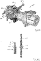
- FIG 1 shows a system 10 in accordance with embodiments described herein.
- the system 10 includes a generally cylindrical first tool arrangement, or live-end assembly 12, and a second tool arrangement, or field-end assembly 14.
- the assemblies 12, 14 are disposed axially adjacent to each other and are supported on a support structure or chassis 16, which includes telescoping tube arrangements 18, 20.
- the tube arrangements 18, 20 include stationary tubes 22, 24 mounted on a chassis plate 26, which cooperate with tubes 28, 30 attached as part of the field-end assembly 14-see Figure 3 .
- the tubes 28, 30 are stationary relative to the field-end assembly 14, they move relative to the stationary tubes 22, 24 when the field-end assembly 14 moves linearly toward and away from the live-end assembly 12.
- Figure 3 also shows a motor and gear arrangement 32 that is operable to move the field-end assembly 14 toward and away from the live-end the assembly 12 along a pair of support rails 34, 36-see also Figure 1 .
- Pinions from the motor and gear arrangement 32 move along a pair of racks 35, 37-see Figure 2 -held in place with rail caps 39, 41.
- an electrical cable 38 mounted on the live-end assembly 12 and having one end 40 prepped for application of an end-cap.
- the cable 38 includes a center conductor 42, and insulation layer 44, an inner layer of semi-conductive material 46, ground straps 48, and an outer insulating jacket material 50.
- the live-end assembly 12 includes a number of tools operable to perform various tasks on a cable, such as the cable 38.
- the live-end assembly 12 is also movable along the rails 22, 24 by operating a motor 52 to drive a lead screw 54.
- the field-end assembly 14 includes an end-cap-cradle assembly 56, a drilling-and-shorting assembly 58, a saw-cutting assembly 60, and a vacuum assembly 62, each of which is explained in more detail below.
- Figure 4 shows the drilling-and-shorting assembly 58, which includes a drilling assembly 64 and a clamping mechanism 66.
- the clamping mechanism 66 includes a latch hook 68 and two side plates 70, 72.
- the latch hook 68 is made from a polymeric material and the two side plates 70, 72 are made from a carbon-fiber composite material, although the use of other materials for the latch hook and side plates is contemplated.
- the clamping mechanism 66 is used to lock into place an electrical cable, such as the cable 38 shown in Figure 1 when the cable is placed in a trough 74 of the drilling-and-shorting assembly 58.
- the clamping mechanism 66 securely holds the cable while the drilling assembly 64 short-circuits and tests the cable.
- the drilling assembly 64 includes a motor 76 operable to rotate a drill bit 78 to penetrate a cable when it is positioned in the trough 74.
- the drill assembly 64 is linearly movable along a track 80 such that it approaches a cable positioned in the trough 74 in a radial direction relative to the cable. Because the entire drilling-and-shorting assembly 58 moves linearly along the racks 35, 37, the drilling assembly 64 can be operated to produce holes in a line along the length of the cable.
- the clamping mechanism 66 can be used to secure the cable just prior to operating the drill assembly 64, and then it can be released to allow the drilling-and-shorting assembly 58 to move linearly relative to the cable to reposition the drill bit 78.
- a camera 82 is positioned proximate to the drill bit 78 to allow an operator to observe the positioning and operation of the drill bit 78.
- the vacuum assembly 62 can be run during or after operation of the drill assembly 64 to collect debris generated during the drilling operation.
- the drilling-and-shorting assembly 58 also includes a test probe 84 that is used to test the effectiveness of the short-circuit produced by the drill bit 78.
- Figure 5 shows the drilling-and-shorting assembly 58, including the drill bit 78 and the test probe 84.
- the drill assembly 64 is configured to hold the drill bit 78 with an ejection mechanism 86 so the drill bit 78 can be quickly released while inside the cable so that it can remain in the cable and maintain a short circuit.
- the drill bit 78 has a hexagonal shank 88 with an area of relief 90-see Figure 6 -into which small ball bearings can fit.
- FIG. 5A shows another view of the drill assembly 64. Rotating the lever 93 in a clockwise direction-as it is oriented in Figure 5A -causes rotation of a yoke 95, which in turn retracts the sleeve 92 to allow the drill bit 78 to be released.
- the test probe 84 includes a flange 94 configured with a number of sharp probes 96, only some of which are labeled for clarity.
- the probes 96 are configured to penetrate an insulating jacket layer of a cable and make electrical contact with the ground straps.
- the test probe 84 also includes an insulating material 98, which surrounds a conductor 100 positioned in the center of the test probe 84.
- Figure 6 shows the drill bit 78 and the test probe 84 both inserted into a field end of an electrical cable 102.
- the electrical cable includes an insulating jacket 104, a layer of ground straps 106, a thin semiconductor layer 107, a relatively thick insulating layer 108, another thin semiconductor layer 109, and a center conductor 110.
- the drill bit 78 has been ejected from the drill assembly 64 and forms a short circuit between the ground straps 106 and the center conductor 110.
- the drill bit 78 is used to create a hole for the probe 84, which may have a depth approximately one half the diameter of the cable 102.
- the field-end assembly 14 is moved linearly so that the drill bit 78 can make a second hole through the cable 102; the drill bit 78 is then ejected from the drill assembly 64 and remains in the cable 102.
- the drill bit 78 includes a number of sharp probes 112 similar to the probes 96 on the test probe 84.
- the probes 112 make a good electrical contact with the ground straps 106, while a cutting portion of the drill bit 78 makes electrical contact with the center conductor of the cable 102, thereby creating the short circuit.
- the test probe 84 is connected to a continuity tester 114, and together, the test probe and continuity tester may conveniently be referred to as a test arrangement 117.
- the test arrangement 117 may emit a signal to a remote position, such as a remotely-positioned operator control panel indicating the continuity-e.g., the electrical resistance-between the center conductor 110 and an outer conductor, in this case the ground straps 106, of the cable 102.
- the signal may, for example, be sent wirelessly to an operator control panel or other device so that an operator may confirm a successful short circuit before approaching the cable.
- FIG. 6A shows a drill bit 103 having a tapered portion 105 on its shank 107.
- the tapered portion 105 is configured to wedge itself into the hole made by the drill bit 103, thereby making contact with the ground straps, such as the ground straps 106 shown in Figure 6 .
- Figure 6A shows a test probe 109 having a conductor 111 surrounded by an insulating layer 113, similar to the test probe 84 shown in Figure 6 .
- the test probe 109 includes a tapered portion 115 on its shank, which is configured to make contact with ground straps when inserted into a hole made by the drill bit 103.
- the saw cutting assembly 60 includes an actuator arrangement 116 for moving the assembly 60 toward and away from an electrical cable, such as the cable 102.
- a motor arrangement 118 drives a band saw 120 around a pair of pulleys 122, 124. Because electrical cable, such as the cable 102 does not already have a cut end when it is placed in a system, such as the system 10, it is not possible to use a bandsaw with a standard configuration to cut through the cable. To solve this problem, the bandsaw 120 used in conjunction with the saw-cutting assembly 60 is twisted 90° at two locations 126, 128 along its length so the cutting teeth have a forward-facing aspect.
- Pairs of rollers 130, 132 help to guide and keep the twisted bandsaw 120 in its proper orientation.
- the saw-cutting assembly 60 is configured with a stop mechanism to ensure that the actuator 116 stops moving the bandsaw 120 forward before the entire saw blade 120-including the back edge-goes through the cut cable. Once the front cutting edge of the bandsaw 120 cuts entirely through the cable, the actuator 116 may easily reverse movement of the saw-cutting assembly 60; however, if the back edge of the bandsaw 120 goes entirely through the cable, it may be very difficult to reverse movement without placing undesirable tension on the bandsaw 120.
- Figures 8A-8D show the field-end assembly 14, and how the drilling-and-shorting assembly 58 is used to eject the electrical cable 102 after it has been cut using the saw-cutting assembly 60.
- the clamping mechanism 66 is actuated to grab the field end of the cable 102 after it has been cut.
- the entire drilling-and-shorting assembly 58 is rotated-clockwise as shown in the figures-with a movement determined by a linkage arrangement 134. Ejecting the field end of the cable 102 allows the live end to be prepped for an end cap as shown in Figures 13-15 .
- FIG 9 shows the live-end assembly 12 detached from the chassis 16.
- the live-end assembly 12 is supported on a carriage assembly 136, which is configured to receive the chassis tubes 22, 24 in openings 138, 140.
- the live-end assembly 12 includes a number of tools for performing work on an electrical cable, such as the cable 38 or the cable 102.
- it includes two scoring tools 142, 144.
- One of the scoring tools 142, 144 can be used to cut into an outer jacket of the electrical cable, while the other of the scoring tools 142, 144 can be used to cut into an inner layer of semiconductor material.
- a tool more specifically designed to remove the semiconductor layers is a rolling tool 146, the operation of which is explained in more detail below in conjunction with Figure 12 .
- a cable cutter 148 is configured to cut through an outer jacket and ground straps of an electrical cable, and a stop mechanism 150 can be adjusted to provide a desired depth for the cable cutter 148.
- a stripping tool 152 includes a cutting portion similar to a lathe tool and is used to strip portions of the insulation from the electrical cable.
- a tool 154 can be used to sweep the cable to remove debris generated by the processing of the various cutters.
- One or more cameras, such as the cameras 156, 158 can be used to provide an operator information regarding the processing of the electrical cable.
- the carriage assembly 136 is shown in Figure 10 , and includes four bushings 160, 162, 164, 166, which support the carriage assembly 136 on the chassis tubes 22, 24.
- the carriage assembly 136 also includes a nut 168 configured to receive the lead screw 54 for moving the live-end assembly 12 toward and away from the field-end assembly 14.
- Figure 11 shows a tool-plate assembly 170 forming a portion of the live-end assembly 12.
- the tool-plate assembly 170 is configured to support an electrical cable on a plurality of rolling elements, which in this embodiment are cylindrical guide rollers 172 positioned around a center of the tool-plate assembly 170.
- the various tools described in conjunction with Figure 9 are mounted on the tool-plate assembly 170.
- the tool-plate assembly 170 may also include a heater, fans, and temperature control for heating the semiconductor layers of the cable to facilitate their removal.
- the tool-plate assembly 170 may also include one or more ratcheting pawls for attaching to a central core of an end cap so that it can be removed from the end cap by moving the live-end assembly 12 away from the end cap.
- Figure 12 shows one of the tools from the tool-plate assembly 170 in more detail.
- the rolling tool 146 is designed to remove one or both of the layers of semiconductor material often found on an electrical cable-see, e.g., the layers 46, 50 shown in Figure 1 or the layers 104, 107 shown in Figure 6 .
- the tool 146 includes a roller 174 having a relatively smooth surface, and in some embodiments may be polished to a very smooth finish.
- the roller 174 which may be made from a metal alloy, is rotated and brought into contact with the semiconductor layer, which it then removes through frictional forces.
- the semiconductor layer may be previously scored, heat can be applied to it, or both, in order to facilitate an easy removal process.
- a small drive mechanism 176 is used to rotate the roller 174, and an actuator 178 is used to position it appropriately and move it as needed along different portions of the semiconductor layer.
- a roller such as the roller 174, may be made from other materials, such as polymers or ceramics.
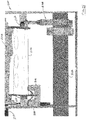
- Figure 13 shows the end-cap-cradle assembly 56 in more detail. Specifically, the assembly 56 is shown positioned on the tubes 22, 24 of the chassis 16-see also Figure 2 .
- the end-cap-cradle assembly 56 includes a cradle 180, which in Figure 13 is holding an end cap 182. A portion of an electrical cable 184 is also held by the live-end assembly 12, which in this view is removed for clarity.
- the cable 184 has a prepared end 186 ready to have the end cap 182 installed on it.
- the cradle 180 can be rotated such that an opening 188 in the end cap 180 is aligned with the prepared end 186 of the cable 184.
- Figure 13 also shows the drill-and-shorting assembly 58 rotated in the eject position after it has ejected the field end of the cable-see also Figure 8D .
- Figure 14 shows the cradle 180, including a portion of a drive mechanism 190 operable to rotate the cradle 180 and the end cap 182 into position.
- the cradle 180 also includes a spring 192 having a relatively high spring constant and a spring 194 having a lower spring constant.
- a pair of micro switches 196, 198 are used in conjunction with the springs 192, 194 to control the insertion force of the end cap 182 onto the cable 184, and also to test correct end-cap installation by limiting a pre-set amount of pull-off force.
- FIG 15 shows an end-cap-cradle assembly 200 similar to, but with a slightly different configuration from, the assembly 56 shown in Figure 13 .
- the assembly 200 includes a cradle 202 configured to hold an end cap 204.
- the assembly 200 is supported on a pair of tubes, including the tube 206, similar to the arrangement shown in Figure 13 .
- an actuator assembly 208 is configured to move the cradle 202 into position so that the end cap 204 is aligned with a prepared end of an electrical cable 210.
- the assembly 200 also includes a spring 212 having a relatively low spring constant, and a spring 214 having a much higher spring constant.
- a first limit switch 216 is configured to check a position of the end cap 204 upon installation onto the cable 210.
- a second limit switch 218 is configured to be used as part of a pull-off test after the end cap 204 is installed onto the cable 210.
- the entire end-cap-cradle assembly 200 is moved linearly-right-to-left as shown in Figure 15 -so that the end cap 204 is positioned over the prepared end of the cable 210.
- the movement continues until the spring 214 is compressed by a reaction force of the cable 210 acting on the end cap 204 and the limit switch 216 is tripped.
- the spring constant of the spring 214 can be set so that an approximate installation force is applied prior to the limit switch 216 being tripped. For example, in some embodiments, this may be approximately 40 pounds of force.
- the spring 214 and the limit switch 216 comprise an installation controller for the end cap configured to position the end cap 204 over the cut end of the cable 210 with a predetermined amount of installation force.
- an end cap such as the end cap 204 is applied to a cable
- a retaining ring in the end cap holds the end cap securely on the electrical cable.
- the end-cap-cradle assembly 200 is moved linearly-left-to right as shown in Figure 15 -to provide an estimation of the retention force between the end cap 204 and the cable 210.
- the spring constant for the spring 212 may be chosen such that approximately 5 pounds of force in the direction of removal will trip the limit switch 218. When this occurs, installation of the end cap 204 is complete. In this way the installation controller also indicates an amount of retention force between the end cap 204 and the cut end of the cable 210.
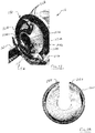
- Figure 16 shows a back side of the live-end assembly 12. In particular, it shows a portion of the tool-plate assembly 170 having an end plate 220-see Figure 18 -removed. Because the various tools and sensors associated with the live-end assembly 12 may require wires for power and communication, one of the issues that needs to be addressed is how to manage the wires when the live-end assembly 12 rotates.
- Figure 16 shows a number of wires 222 contained within an elongated flexible cable carrier 224.
- the cable carrier 224 is configured as a chain having jointed links that facilitates rotation in clockwise and counterclockwise directions.
- the tool-plate assembly 170 has been rotated in a counterclockwise direction, thereby wrapping the cable carrier 224 around a hub 226 of the tool-plate assembly 170.
- the hub 226 is disposed proximate to a center portion 227 of the live-end assembly 12. Because embodiments of a live-end assembly, such as the live-end assembly 12, may rotate 360° or more in either direction, it is desirable to guide the cable carrier 224 so that it does not fold back onto itself or otherwise bind, which could lead to an undesirable amount of stress on the links of the cable carrier 224.
- One way that managing the cable carrier 224 can be accomplished is by attaching fasteners such as magnets 228 to the cable carrier 224 and providing steel guide strips 230, 232, 234 to which the magnets 228 may adhere.
- the magnets 228 secure a position of the cable carrier 224 when it is wound around the hub 226.
- the cable carrier 224 may be provided with additional magnets 228 on the inside or outside of the links.
- several of the magnets 228 may be placed on an inside of the cable carrier 224 so that it is securely attached to the metal guide strip 234 surrounding the hub 226.
- Figure 17 shows the live-end assembly 12 after it has been rotated clockwise from the orientation shown in Figure 16 .
- the cable carrier 224 has started to unwind, revealing a number of the magnets 228 attached to the inside of the cable carrier 224, which now becomes an outside of the cable carrier 224 as its orientation changes.
- the fasteners used in this embodiment were magnets, other fasteners may be used, such as a hook-and-loop system or other device for maintaining a position of the cable carrier 224 while allowing it to be wrapped around and unwrapped from a hub 226 on the tool-plate assembly 170.
- the live-end assembly 12 uses two limit switches 236, 238 to limit rotation of the tool-plate assembly 170.
- the limit switches 236, 238 work in conjunction with the end plate 220, and in particular, with tabs 240, 242, respectively.
- the limit switches 236, 238 are axially offset from each other-i.e., they are positioned at different points along a longitudinal axis 244 of the live-end assembly 12.
- the tabs 240, 242 are also axially offset from each other at a distance that coincides with the distance between the limit switches 236, 238.
- the tool-plate assembly 170 also includes a magnetic reed switch 246 positioned inside a housing 248 of the tool-plate assembly 170.
- the cable carrier 224 is wrapped around the hub 226 so that one or more of the magnets 228 will be in close proximity to the reed switch 246, which will be actuated.
- the tabs 240, 242 will be oriented downward as shown in Figure 16 .
- Figure 18 the inside of the end plate 220 is shown such that when it is installed on the tool-plate assembly 170 with the tabs 240, 242 facing downward, the tab 242 will be on the left and the tab 240 will be on the right.
- the cable carrier 224 will be unwound from the hub 226 and the reed switch 246 will be unactuated-see Figure 17 . This alerts the system 10 that the tool-plate assembly 170 has been rotated in a clockwise direction. If the tool-plate assembly 170 is further rotated in the clockwise direction, the tab 240 will trip the limit switch 236, indicating that further rotation in the clockwise direction would be undesirable, and the system may prohibit further clockwise rotation of the tool-plate assembly 170.
- Figure 19 shows a sequence of clockwise and counterclockwise rotations of a tool-plate assembly and how the tabs T1 and T2, the limit switches L1 and L2, and the reed switch work together to ensure that rotation is properly limited.
- Figure 19 the outside of the end plate is shown, which is the opposite orientation from the end plate 220 shown in Figure 18 .
- the tool-plate assembly 170 includes an opening 250 that is configured as a slot along a length of the tool-plate assembly 170 and radially oriented between an outer portion 252 and a center portion 254 of the tool-plate assembly 170, and by extension the live-end assembly 12.
- the center portion 254 refers to a radial center of the tool-plate assembly 170, rather than a longitudinal center portion.
- the configuration of the opening 250 allows a cable, such as the cable 38, to be inserted into the live-end assembly 12 before it is cut.
- the guide rollers 172 act as guide elements and support the cable so that the various tools of the live-end assembly 12 can perform work on the cable.
- each of the guide elements is configured as a cylindrical guide roller 172; however, in other embodiments, some or all of the guide elements may have different shapes or may be stationary.
- each of the drive arrangements 264, 266, 268 is configured the same, and although they are identified separately as three different drive arrangements, they may be considered part of single drive arrangement 269, which controls movement of the guide arrangement 256 and all of the guide rollers 172.
- the drive arrangement 264 as an example of the operation of all three drive arrangements 264, 266, 268, it includes a rack-and-pinion arrangement 270 having a motor 272, which drives to pinion gears 274, 276 along a rack 278 to move the pair 258 of guide rollers 172 radially inward and outward.
- guide arrangements may be configured differently, for example, with a drive screw or other linear actuating arrangement, such as a pneumatic or hydraulic cylinder.
- Each of the pairs of guide rollers 258, 260, 262 is separately movable inward and outward. This helps to accurately position a cable for the required operations. Specifically, it may be important that the cable has a constant radial position relative to the tools on the live-end assembly while it is being cut and the various insulating and conducting layers are being prepared to receive the end-cap.
- the configuration of guide rollers 172 with their associated drive arrangements 264, 266, 268 provides that secure positioning.
- FIG. 21 shows a configuration in accordance with embodiments described herein that includes two guide arrangements 280, 282 axially spaced from each other along an axis 284, which is coincident with an axis of a cable secured in the guide arrangements 280, 282-see, for example, the cable axis 251 in Figure 1 .
- the guide arrangement 280 includes guide elements, or guide rollers 286, and the guide arrangement 282 includes guide elements, or guide rollers 288, not all of which are labeled for clarity.
- the guide elements 286 and the guide elements 288 are disposed symmetrically around the axis 284, which helps to ensure that a cable captured in the guide arrangements 280, 282 will be securely held in place by the guide elements 286, 288 when the tools from a live-end assembly, such as the live-end assembly 12, are operating on the cable.
- Each of the guide arrangements 280, 282 is configured similarly to the guide arrangement 256 shown in figure 20 , and respectively includes drive arrangements 290, 292, 294 and drive arrangements 296, 298, 300.
- Including more than one of the guide arrangements, such as the guide arrangements 280, 282, positioned axially from each other along the cable helps to stabilize the cable and keep it accurately positioned. Accurate positioning, including keeping the cable straight, may be important for a number of reasons.
- the tools of a live-end assembly are designed to operate in a specific orientation and direction.
- a cutting edge of a cutting tool will be positioned in a fixed orientation relative to a straight cable. If the cable is bent, the cutting edge will no longer possess the correct orientation to perform the cut. Also, the tool may no longer be able to reach the cable.
- guide elements such as the guide elements 286, 288, to straighten the cable may be required to properly prepare the cable for installation of the end cap.
- having a straight cable end can be necessary for the application of the end cap after the cable is prepared.
- FIG 22 shows a live-end assembly 302 that includes an opening 304 configured to receive a cable 306. Similar to the live-end assembly 12, the live-end assembly 302 includes a plurality of tools 304, 306, 308, 310, 312, 314 configured to perform one or more operations on the cable 306. As shown in Figure 22 , the cable 306 already has one end 316 prepared to receive an end-cap. In the embodiment shown in figure 22 , however, the live-end assembly 302 includes two guide arrangements 318, 320 spaced apart from each other axially along the length of the cable 306. As shown in Figure 22 , the guide arrangement 320 is clamped securely on the outer insulation 322 of the cable 306, while the guide arrangement 318 is secured to an inner insulating layer 324 of the cable 306.
- the first guide arrangement 318 is associated with the tools 304, 306, 308, 310, 312, 314, while the second guide arrangement 320 is not associated with any tools and merely provides additional clamping to secure the cable 306 in a desired position.
- both guide arrangements 318, 320 are part of the live-end assembly 302, but in other embodiments, guide arrangements, such as the guide arrangements 318, 320, may be separate from any tool arrangement and may be, for example, separately supported on a support structure, such as the chassis 16-see Figure 1 .
- a cable may be positioned so that its cut end extends farther outward from the guide arrangement 318, in which case another guide arrangement may be positioned in front of the tools to further stabilize and accurately position the cable end.
- the guide arrangements 256, 280, 318, 320 are all configured with three pairs of guide elements, which in these embodiments are guide rollers.
- a set of guide elements may not be arranged in a pair; they may include a single guide element in each set, or three or more guide elements in each set.
- less than three sets or more than three sets of the guide elements may be used, although three sets symmetrically positioned around a cable axis-such as shown in Figures 20-22 -may be desirable.
- each of the sets of guide elements is independently movable.
- a system such as the system 10, may include a plurality of live-end assemblies, two or more of which may include one or more guide arrangements and associated sets of tools.
- multiple guide arrangements may be positioned at a fixed axial distance from each other, while in others, one or both of the guide arrangements may be movable axially relative to the other to provide optimal positioning for securing a cable and positioning it for the work to be performed by the tools and the application of an end-cap.
Landscapes
- Installation Of Indoor Wiring (AREA)
- Testing Of Short-Circuits, Discontinuities, Leakage, Or Incorrect Line Connections (AREA)
Abstract
Description
- This application claims the benefit of
U.S. provisional application Serial No. 62/780,390 filed December 17, 2018 - The present disclosure relates to a system for servicing cable.
- Because of the high density of demand for electric power in urban areas, an underground distribution network system is commonly used. The distribution network system typically includes conduits under the street pavement with primary splicing structures-e.g., manholes-every 300 to 500 feet and secondary splicing structures-e.g., secondary boxes-every 100 to 150 feet. Distribution-network feeders operate at different voltages-for example, in some applications, 13 kilovolt (kV) and 27kV feeders are commonly used. The distribution-network feeders consist of three cables that are A, B, and C phase. These feeders are installed in conduits to transport electricity from the supply substation to several distribution-network transformers. Unlike overhead open-wire feeders, where larger clearances are available to facilitate live-line work, underground cable feeders may need to be de-energized in order to perform work. Because of the multipath characteristics of a network system, a feeder outage may not be immediately reflected in customer outages, but instead, may result in added stress to the components remaining in service and lower supply voltage to customers.
- A live end-cap (LEC) is a splice that is often used during adverse system conditions to expedite feeder restoration. An LEC process includes separating a cable connection and insulating part of it to allow the selected portion of the feeder to be re-energized. Once an LEC is installed, a smaller, less critical portion of the feeder is dropped, and the rest of the feeder is energized back into service. Installing an LEC may be simpler and quicker than performing a complete repair during an outage. Despite advances in the process for installing LEC's, a need exists for a system and method of servicing a cable-for example, to install a live end-cap or to splice one or more cable sections together to create a single conductive path-that utilizes one or more machines to perform tasks that would otherwise need to be performed manually by technicians, and which may provide an automated or semi-automated system and process to improve the installation tasks.
- Embodiments described herein include a system for servicing cable. The system may include a chassis that supports two assemblies: a field-end assembly for performing operations on a field end of an electrical cable, and a live-end assembly for performing operations on a live end of the electrical cable. The chassis may be constructed with one or more rails that facilitate linear movement of one or both of the assemblies. At least some embodiments may include stationary tubes that serve as supports for a set of outer tubes to provide telescoping action for moving one of the assemblies linearly along the rails. Some embodiments may also or alternatively include a lead screw connected to a motor drive for moving one of the assemblies linearly toward and away from the other of the assemblies.
- Embodiments described herein may further include various systems, subsystems, assemblies, and subassemblies capable of performing one or more operations on an electrical cable. For example, some embodiments may include a drilling-and-shorting assembly for creating a short circuit in a field-end of the cable, and may also include a continuity tester for testing the integrity of the short-circuit. Some embodiments may include an end-cap cradle assembly for positioning an end cap on a live end of an electrical cable. Embodiments may also include one or more tools for cutting an electrical cable; removing one or more layers of insulation, and ejecting the cable from the system. Embodiments described herein may not only automate and simplify processes currently performed manually, but may also allow some steps required with a manual process to be completely eliminated, thereby further increasing speed and efficiency of the process.
- At least some embodiments described herein may include a system for servicing cable that includes a support structure and first and second tool arrangements. The first tool arrangement is supported on the support structure and includes an opening configured to receive a cable in a direction transverse to a cable axis and at least one tool operable to perform one or more operations on a cable received in the opening. The second tool arrangement is supported on the support structure and includes at least one tool operable to perform one or more operations on a cable received by the first tool arrangement. At least one of the first or second tool arrangement is movable axially along the support structure relative to the other tool arrangement. A guide arrangement includes a plurality of guide elements, and a drive arrangement is configured to move at least one of the guide elements into contact with and apply a force to a cable received by the first tool arrangement. The drive arrangement is operable to vary the force to adjust a position of a cable received by the first tool arrangement.
- At least some embodiments described herein may include a system for servicing cable that includes a support structure and first and second tool arrangements supported on the support structure. At least one of the tool arrangements is movable axially relative to the other tool arrangement. The first tool arrangement includes a center portion configured to receive a cable therein, and further includes at least one tool operable to perform one or more operations on a cable received in the center portion. A plurality of guide elements are movable radially outward away from the center portion of the first tool arrangement to facilitate positioning of a cable in the center portion, and they are movable radially inward toward the center portion to exert forces on and secure a cable in the center portion of the first tool arrangement. At least one of the guide elements is separately movable from at least one other of the guide elements such that a position of a cable in the center portion of the first tool arrangement is adjustable by the guide elements.
- At least some embodiments described herein may include a system for servicing cable that includes a support structure and a first tool arrangement supported on the support structure and having a center portion configured to receive a cable therein. A second tool arrangement is disposed axially adjacent to the first tool arrangement and supported on the support structure. A plurality of guide elements is disposed around the center portion of the first tool arrangement, and a plurality of independently operable drive arrangements are each operable to move at least one of the guide elements away from the center portion of the first tool arrangement such that a cable is receivable by the first tool arrangement and toward the center portion of the first tool arrangement such that the guide elements secure a cable received by the first tool arrangement.
-
-
FIGURE 1 shows a system for servicing cable in accordance with embodiments described herein; -
FIGURE 2 shows a chassis from the system shown inFigure 1 ; -
FIGURE 3 shows a field-end assembly from the system shown inFigure 1 ; -
FIGURE 4 shows a drilling-and-shorting assembly from the field-end assembly; -
FIGURE 5 shows a drill assembly, including a cable continuity tester from the drilling-and-shorting assembly; -
FIGURE 5A shows details of the drill assembly; -
FIGURE 6 shows the cable continuity tester in use; -
FIGURE 6A shows a drill bit and continuity tester in accordance with another embodiment described herein; -
FIGURE 7 shows a saw-cutting assembly from the field-end assembly; -
FIGURES 8A-8D show a cable-eject mechanism from the field-end assembly; -
FIGURE 9 shows a live-end assembly from the system shown inFigure 1 ; -
FIGURE 10 shows a carriage assembly from the live-end assembly; -
FIGURE 11 shows a tool-plate assembly from the live-end assembly; -
FIGURE 12 shows a semi-conductor removal tool from the live-end assembly: -
FIGURE 13 shows an end-cap-cradle assembly from the field-end assembly holding an end cap ready for installation; -
FIGURE 14 shows an end-cap-cradle assembly from the field-end assembly; -
FIGURE 15 shows an end cap installed on a cable end prepared for a pull-back test; -
FIGURE 16 shows a portion of the tool-plate assembly with a flexible cable carrier wrapped around a hub in one direction; -
FIGURE 17 shows a portion the tool-plate assembly with the flexible cable carrier wrapped around the hub in the opposite direction; -
FIGURE 18 shows an end plate for the tool-plate assembly; -
FIGURE 19 shows operation of a rotation-limiting system for the tool-plate assembly -
FIGURE 20 shows details of a guide arrangement with a plurality of guide rollers; -
FIGURE 21 shows a pair of guide arrangements spaced axially from each other; and -
FIGURE 22 shows a live-end assembly having two guide arrangements securing a cut end of an electrical cable. - As required, detailed embodiments of the present invention are disclosed herein; however, it is to be understood that the disclosed embodiments are merely exemplary of the invention that may be embodied in various and alternative forms. The figures are not necessarily to scale; some features may be exaggerated or minimized to show details of particular components. Therefore, specific structural and functional details disclosed herein are not to be interpreted as limiting, but merely as a representative basis for teaching one skilled in the art to variously employ the present invention.
-
Figure 1 shows asystem 10 in accordance with embodiments described herein. Thesystem 10 includes a generally cylindrical first tool arrangement, or live-end assembly 12, and a second tool arrangement, or field-end assembly 14. Theassemblies chassis 16, which includestelescoping tube arrangements Figure 2 , thetube arrangements stationary tubes chassis plate 26, which cooperate withtubes Figure 3 . Although thetubes end assembly 14, they move relative to thestationary tubes end assembly 14 moves linearly toward and away from the live-end assembly 12.Figure 3 also shows a motor andgear arrangement 32 that is operable to move the field-end assembly 14 toward and away from the live-end theassembly 12 along a pair of support rails 34, 36-see alsoFigure 1 . Pinions from the motor andgear arrangement 32 move along a pair ofracks 35, 37-seeFigure 2 -held in place with rail caps 39, 41. - Also shown in
Figure 1 is anelectrical cable 38 mounted on the live-end assembly 12 and having one end 40 prepped for application of an end-cap. Thecable 38 includes acenter conductor 42, and insulation layer 44, an inner layer ofsemi-conductive material 46, ground straps 48, and an outer insulatingjacket material 50. As explained in more detail in conjunction withFigures 7 and8 , the live-end assembly 12 includes a number of tools operable to perform various tasks on a cable, such as thecable 38. The live-end assembly 12 is also movable along therails lead screw 54. - Turning to
Figures 3 and 4 , details of the field-end assembly 14 are shown. The field-end assembly 14 includes an end-cap-cradle assembly 56, a drilling-and-shortingassembly 58, a saw-cuttingassembly 60, and avacuum assembly 62, each of which is explained in more detail below.Figure 4 shows the drilling-and-shortingassembly 58, which includes adrilling assembly 64 and aclamping mechanism 66. Theclamping mechanism 66 includes alatch hook 68 and two side plates 70, 72. In the embodiment shown inFigure 4 , thelatch hook 68 is made from a polymeric material and the two side plates 70, 72 are made from a carbon-fiber composite material, although the use of other materials for the latch hook and side plates is contemplated. Theclamping mechanism 66 is used to lock into place an electrical cable, such as thecable 38 shown inFigure 1 when the cable is placed in atrough 74 of the drilling-and-shortingassembly 58. Theclamping mechanism 66 securely holds the cable while thedrilling assembly 64 short-circuits and tests the cable. - The
drilling assembly 64 includes amotor 76 operable to rotate adrill bit 78 to penetrate a cable when it is positioned in thetrough 74. Thedrill assembly 64 is linearly movable along a track 80 such that it approaches a cable positioned in thetrough 74 in a radial direction relative to the cable. Because the entire drilling-and-shortingassembly 58 moves linearly along theracks drilling assembly 64 can be operated to produce holes in a line along the length of the cable. Theclamping mechanism 66 can be used to secure the cable just prior to operating thedrill assembly 64, and then it can be released to allow the drilling-and-shortingassembly 58 to move linearly relative to the cable to reposition thedrill bit 78. Acamera 82 is positioned proximate to thedrill bit 78 to allow an operator to observe the positioning and operation of thedrill bit 78. Thevacuum assembly 62 can be run during or after operation of thedrill assembly 64 to collect debris generated during the drilling operation. As explained in more detail in conjunction withFigures 5 and 6 , the drilling-and-shortingassembly 58 also includes atest probe 84 that is used to test the effectiveness of the short-circuit produced by thedrill bit 78. -
Figure 5 shows the drilling-and-shortingassembly 58, including thedrill bit 78 and thetest probe 84. Thedrill assembly 64 is configured to hold thedrill bit 78 with anejection mechanism 86 so thedrill bit 78 can be quickly released while inside the cable so that it can remain in the cable and maintain a short circuit. In the embodiment shown inFigure 5 , thedrill bit 78 has ahexagonal shank 88 with an area of relief 90-seeFigure 6 -into which small ball bearings can fit. Acollar 92 of the drill-bit-eject mechanism 86 maintains the ball bearings in therelief 90 of theshank 88, but when it is retracted by alever 93 or apiston 97, the ball bearings are free to move out of therelief area 90 and thedrill bit 78 can be removed from thedrill assembly 64.Figure 5A shows another view of thedrill assembly 64. Rotating thelever 93 in a clockwise direction-as it is oriented inFigure 5A -causes rotation of ayoke 95, which in turn retracts thesleeve 92 to allow thedrill bit 78 to be released. - Returning to
Figure 5 , it is shown that thetest probe 84 includes aflange 94 configured with a number ofsharp probes 96, only some of which are labeled for clarity. Theprobes 96 are configured to penetrate an insulating jacket layer of a cable and make electrical contact with the ground straps. Thetest probe 84 also includes an insulatingmaterial 98, which surrounds aconductor 100 positioned in the center of thetest probe 84.Figure 6 shows thedrill bit 78 and thetest probe 84 both inserted into a field end of anelectrical cable 102. The electrical cable includes an insulatingjacket 104, a layer of ground straps 106, athin semiconductor layer 107, a relatively thickinsulating layer 108, anotherthin semiconductor layer 109, and acenter conductor 110. As shown inFigure 6 , thedrill bit 78 has been ejected from thedrill assembly 64 and forms a short circuit between the ground straps 106 and thecenter conductor 110. As part of the drilling-and-shorting process, thedrill bit 78 is used to create a hole for theprobe 84, which may have a depth approximately one half the diameter of thecable 102. Next, the field-end assembly 14 is moved linearly so that thedrill bit 78 can make a second hole through thecable 102; thedrill bit 78 is then ejected from thedrill assembly 64 and remains in thecable 102. - As shown in
Figure 6 , thedrill bit 78 includes a number ofsharp probes 112 similar to theprobes 96 on thetest probe 84. Theprobes 112 make a good electrical contact with the ground straps 106, while a cutting portion of thedrill bit 78 makes electrical contact with the center conductor of thecable 102, thereby creating the short circuit. Thetest probe 84 is connected to acontinuity tester 114, and together, the test probe and continuity tester may conveniently be referred to as atest arrangement 117. Thetest arrangement 117 may emit a signal to a remote position, such as a remotely-positioned operator control panel indicating the continuity-e.g., the electrical resistance-between thecenter conductor 110 and an outer conductor, in this case the ground straps 106, of thecable 102. The signal may, for example, be sent wirelessly to an operator control panel or other device so that an operator may confirm a successful short circuit before approaching the cable. - As an alternative to the
sharp probes 112 on thedrill bit 78 and thesharp probes 96 on thetest probe 84, contact can be made with the ground straps using portions of the drill bit body and the test probe body, respectively.Figure 6A shows adrill bit 103 having a taperedportion 105 on itsshank 107. The taperedportion 105 is configured to wedge itself into the hole made by thedrill bit 103, thereby making contact with the ground straps, such as the ground straps 106 shown inFigure 6 . Similarly,Figure 6A shows atest probe 109 having a conductor 111 surrounded by an insulatinglayer 113, similar to thetest probe 84 shown inFigure 6 . Instead of thesharp probes 112, however, thetest probe 109 includes a taperedportion 115 on its shank, which is configured to make contact with ground straps when inserted into a hole made by thedrill bit 103. - After it is determined that the short circuit has been effectively made, a cut is made entirely through the
cable 102, so that the field end can be ejected from thesystem 10. One way to perform this cutting is to use a saw-cutting assembly, such as the saw-cuttingassembly 60 shown inFigure 3 -see alsoFigure 7 . Thesaw cutting assembly 60 includes anactuator arrangement 116 for moving theassembly 60 toward and away from an electrical cable, such as thecable 102. A motor arrangement 118 drives aband saw 120 around a pair ofpulleys cable 102 does not already have a cut end when it is placed in a system, such as thesystem 10, it is not possible to use a bandsaw with a standard configuration to cut through the cable. To solve this problem, thebandsaw 120 used in conjunction with the saw-cuttingassembly 60 is twisted 90° at twolocations - Pairs of
rollers twisted bandsaw 120 in its proper orientation. The saw-cuttingassembly 60 is configured with a stop mechanism to ensure that theactuator 116 stops moving thebandsaw 120 forward before the entire saw blade 120-including the back edge-goes through the cut cable. Once the front cutting edge of thebandsaw 120 cuts entirely through the cable, theactuator 116 may easily reverse movement of the saw-cuttingassembly 60; however, if the back edge of thebandsaw 120 goes entirely through the cable, it may be very difficult to reverse movement without placing undesirable tension on thebandsaw 120. -
Figures 8A-8D show the field-end assembly 14, and how the drilling-and-shortingassembly 58 is used to eject theelectrical cable 102 after it has been cut using the saw-cuttingassembly 60. Theclamping mechanism 66 is actuated to grab the field end of thecable 102 after it has been cut. The entire drilling-and-shortingassembly 58 is rotated-clockwise as shown in the figures-with a movement determined by a linkage arrangement 134. Ejecting the field end of thecable 102 allows the live end to be prepped for an end cap as shown inFigures 13-15 . -
Figure 9 shows the live-end assembly 12 detached from thechassis 16. The live-end assembly 12 is supported on acarriage assembly 136, which is configured to receive thechassis tubes openings end assembly 12 includes a number of tools for performing work on an electrical cable, such as thecable 38 or thecable 102. For example, it includes twoscoring tools 142, 144. One of thescoring tools 142, 144 can be used to cut into an outer jacket of the electrical cable, while the other of thescoring tools 142, 144 can be used to cut into an inner layer of semiconductor material. A tool more specifically designed to remove the semiconductor layers is a rollingtool 146, the operation of which is explained in more detail below in conjunction withFigure 12 . - A
cable cutter 148 is configured to cut through an outer jacket and ground straps of an electrical cable, and astop mechanism 150 can be adjusted to provide a desired depth for thecable cutter 148. A strippingtool 152 includes a cutting portion similar to a lathe tool and is used to strip portions of the insulation from the electrical cable. Atool 154 can be used to sweep the cable to remove debris generated by the processing of the various cutters. One or more cameras, such as thecameras carriage assembly 136 is shown inFigure 10 , and includes fourbushings carriage assembly 136 on thechassis tubes carriage assembly 136 also includes anut 168 configured to receive thelead screw 54 for moving the live-end assembly 12 toward and away from the field-end assembly 14. -
Figure 11 shows a tool-plate assembly 170 forming a portion of the live-end assembly 12. The tool-plate assembly 170 is configured to support an electrical cable on a plurality of rolling elements, which in this embodiment arecylindrical guide rollers 172 positioned around a center of the tool-plate assembly 170. The various tools described in conjunction withFigure 9 are mounted on the tool-plate assembly 170. In addition, the tool-plate assembly 170 may also include a heater, fans, and temperature control for heating the semiconductor layers of the cable to facilitate their removal. The tool-plate assembly 170 may also include one or more ratcheting pawls for attaching to a central core of an end cap so that it can be removed from the end cap by moving the live-end assembly 12 away from the end cap. -
Figure 12 shows one of the tools from the tool-plate assembly 170 in more detail. In particular, it shows the rollingtool 146. The rollingtool 146 is designed to remove one or both of the layers of semiconductor material often found on an electrical cable-see, e.g., thelayers Figure 1 or thelayers Figure 6 . Thetool 146 includes aroller 174 having a relatively smooth surface, and in some embodiments may be polished to a very smooth finish. Theroller 174, which may be made from a metal alloy, is rotated and brought into contact with the semiconductor layer, which it then removes through frictional forces. The semiconductor layer may be previously scored, heat can be applied to it, or both, in order to facilitate an easy removal process. Asmall drive mechanism 176 is used to rotate theroller 174, and anactuator 178 is used to position it appropriately and move it as needed along different portions of the semiconductor layer. In other embodiments, a roller, such as theroller 174, may be made from other materials, such as polymers or ceramics. -
Figure 13 shows the end-cap-cradle assembly 56 in more detail. Specifically, theassembly 56 is shown positioned on thetubes Figure 2 . The end-cap-cradle assembly 56 includes acradle 180, which inFigure 13 is holding anend cap 182. A portion of anelectrical cable 184 is also held by the live-end assembly 12, which in this view is removed for clarity. Thecable 184 has aprepared end 186 ready to have theend cap 182 installed on it. Thecradle 180 can be rotated such that anopening 188 in theend cap 180 is aligned with theprepared end 186 of thecable 184.Figure 13 also shows the drill-and-shortingassembly 58 rotated in the eject position after it has ejected the field end of the cable-see alsoFigure 8D . -
Figure 14 shows thecradle 180, including a portion of adrive mechanism 190 operable to rotate thecradle 180 and theend cap 182 into position. Thecradle 180 also includes aspring 192 having a relatively high spring constant and aspring 194 having a lower spring constant. As explained in more detail in conjunction withFigure 15 , a pair ofmicro switches springs end cap 182 onto thecable 184, and also to test correct end-cap installation by limiting a pre-set amount of pull-off force. -
Figure 15 shows an end-cap-cradle assembly 200 similar to, but with a slightly different configuration from, theassembly 56 shown inFigure 13 . Theassembly 200 includes a cradle 202 configured to hold anend cap 204. Theassembly 200 is supported on a pair of tubes, including thetube 206, similar to the arrangement shown inFigure 13 . In this embodiment, anactuator assembly 208 is configured to move the cradle 202 into position so that theend cap 204 is aligned with a prepared end of anelectrical cable 210. Theassembly 200 also includes a spring 212 having a relatively low spring constant, and aspring 214 having a much higher spring constant. Afirst limit switch 216 is configured to check a position of theend cap 204 upon installation onto thecable 210. Asecond limit switch 218 is configured to be used as part of a pull-off test after theend cap 204 is installed onto thecable 210. - Once the
end cap 204 is aligned with thecable 210, the entire end-cap-cradle assembly 200 is moved linearly-right-to-left as shown inFigure 15 -so that theend cap 204 is positioned over the prepared end of thecable 210. The movement continues until thespring 214 is compressed by a reaction force of thecable 210 acting on theend cap 204 and thelimit switch 216 is tripped. The spring constant of thespring 214 can be set so that an approximate installation force is applied prior to thelimit switch 216 being tripped. For example, in some embodiments, this may be approximately 40 pounds of force. In this way, thespring 214 and thelimit switch 216 comprise an installation controller for the end cap configured to position theend cap 204 over the cut end of thecable 210 with a predetermined amount of installation force. When an end cap such as theend cap 204 is applied to a cable, a retaining ring in the end cap holds the end cap securely on the electrical cable. To help ensure that installation has been performed correctly, the end-cap-cradle assembly 200 is moved linearly-left-to right as shown inFigure 15 -to provide an estimation of the retention force between theend cap 204 and thecable 210. In the embodiment shown inFigure 15 , the spring constant for the spring 212 may be chosen such that approximately 5 pounds of force in the direction of removal will trip thelimit switch 218. When this occurs, installation of theend cap 204 is complete. In this way the installation controller also indicates an amount of retention force between theend cap 204 and the cut end of thecable 210. -
Figure 16 shows a back side of the live-end assembly 12. In particular, it shows a portion of the tool-plate assembly 170 having an end plate 220-seeFigure 18 -removed. Because the various tools and sensors associated with the live-end assembly 12 may require wires for power and communication, one of the issues that needs to be addressed is how to manage the wires when the live-end assembly 12 rotates.Figure 16 shows a number of wires 222 contained within an elongatedflexible cable carrier 224. Thecable carrier 224 is configured as a chain having jointed links that facilitates rotation in clockwise and counterclockwise directions. As shown inFigure 16 , the tool-plate assembly 170 has been rotated in a counterclockwise direction, thereby wrapping thecable carrier 224 around ahub 226 of the tool-plate assembly 170. As shown inFigure 16 , thehub 226 is disposed proximate to acenter portion 227 of the live-end assembly 12. Because embodiments of a live-end assembly, such as the live-end assembly 12, may rotate 360° or more in either direction, it is desirable to guide thecable carrier 224 so that it does not fold back onto itself or otherwise bind, which could lead to an undesirable amount of stress on the links of thecable carrier 224. - One way that managing the
cable carrier 224 can be accomplished is by attaching fasteners such asmagnets 228 to thecable carrier 224 and providing steel guide strips 230, 232, 234 to which themagnets 228 may adhere. Themagnets 228 secure a position of thecable carrier 224 when it is wound around thehub 226. Although only two of themagnets 228 are shown inFigure 16 , it is understood that thecable carrier 224 may be provided withadditional magnets 228 on the inside or outside of the links. For example, several of themagnets 228 may be placed on an inside of thecable carrier 224 so that it is securely attached to themetal guide strip 234 surrounding thehub 226.Figure 17 shows the live-end assembly 12 after it has been rotated clockwise from the orientation shown inFigure 16 . In this view, thecable carrier 224 has started to unwind, revealing a number of themagnets 228 attached to the inside of thecable carrier 224, which now becomes an outside of thecable carrier 224 as its orientation changes. Although the fasteners used in this embodiment were magnets, other fasteners may be used, such as a hook-and-loop system or other device for maintaining a position of thecable carrier 224 while allowing it to be wrapped around and unwrapped from ahub 226 on the tool-plate assembly 170. - Although some embodiments of a live-end assembly, such as the live-
end assembly 12, may have one or more mechanical stops to ensure that rotation does not go beyond a desired limit, other ways of ensuring a limited rotation may also be provided. In the embodiment shown inFigures 16 and17 , the live-end assembly 12 uses twolimit switches plate assembly 170. The limit switches 236, 238 work in conjunction with theend plate 220, and in particular, withtabs longitudinal axis 244 of the live-end assembly 12. Similarly, thetabs limit switches tabs limit switches plate assembly 170 also includes amagnetic reed switch 246 positioned inside a housing 248 of the tool-plate assembly 170. - As shown in
Figure 16 , thecable carrier 224 is wrapped around thehub 226 so that one or more of themagnets 228 will be in close proximity to thereed switch 246, which will be actuated. This indicates that the tool-plate assembly 170 has been rotated in a counterclockwise orientation at least enough to have thecable carrier 224 cover thehub 226. When theend plate 220 is attached to the tool-plate assembly 170, thetabs Figure 16 . InFigure 18 , the inside of theend plate 220 is shown such that when it is installed on the tool-plate assembly 170 with thetabs tab 242 will be on the left and thetab 240 will be on the right. Because thesystem 10 knows that the tool-plate assembly 170 is already rotated significantly in a counterclockwise direction, further counterclockwise rotation would cause thetab 242 to trip thelimit switch 238, indicating that further rotation in that direction would be undesirable, and the system may prohibit further rotation of the tool-plate assembly 170 in the counterclockwise direction. - If the tool-
plate assembly 170 is rotated in a clockwise direction, thecable carrier 224 will be unwound from thehub 226 and thereed switch 246 will be unactuated-seeFigure 17 . This alerts thesystem 10 that the tool-plate assembly 170 has been rotated in a clockwise direction. If the tool-plate assembly 170 is further rotated in the clockwise direction, thetab 240 will trip thelimit switch 236, indicating that further rotation in the clockwise direction would be undesirable, and the system may prohibit further clockwise rotation of the tool-plate assembly 170.Figure 19 shows a sequence of clockwise and counterclockwise rotations of a tool-plate assembly and how the tabs T1 and T2, the limit switches L1 and L2, and the reed switch work together to ensure that rotation is properly limited. InFigure 19 the outside of the end plate is shown, which is the opposite orientation from theend plate 220 shown inFigure 18 . - As shown in
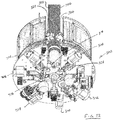
Figure 11 , the tool-plate assembly 170 includes anopening 250 that is configured as a slot along a length of the tool-plate assembly 170 and radially oriented between anouter portion 252 and acenter portion 254 of the tool-plate assembly 170, and by extension the live-end assembly 12. In the embodiment shown inFigure 11 , thecenter portion 254 refers to a radial center of the tool-plate assembly 170, rather than a longitudinal center portion. The configuration of theopening 250 allows a cable, such as thecable 38, to be inserted into the live-end assembly 12 before it is cut. More specifically, it allows a cable to be inserted into theopening 250 in a direction transverse to a cable axis-see, e.g., thecable 38 havingcable axis 251 inFigure 1 . As described above, theguide rollers 172 act as guide elements and support the cable so that the various tools of the live-end assembly 12 can perform work on the cable. - In order to position the cable in the
center portion 254, theguide rollers 172 are movable into and away from thecenter portion 254. Theguide rollers 172 are shown in more detail inFigure 20 . Specifically, theguide rollers 172 are shown to be part of aguide arrangement 256 that includes threepairs guide rollers 172. Each of thepairs respective drive arrangement 264, 266, 268, which may be actuated to move theguide rollers 172 away from thecenter portion 254 to allow the cable to be inserted into the live-end assembly 12, and then actuated to move theguide rollers 172 toward the cable to secure it for subsequent operations. In the embodiment shown inFigure 11 , each of the guide elements is configured as acylindrical guide roller 172; however, in other embodiments, some or all of the guide elements may have different shapes or may be stationary. - In the embodiment shown in
Figure 20 , each of thedrive arrangements 264, 266, 268 is configured the same, and although they are identified separately as three different drive arrangements, they may be considered part ofsingle drive arrangement 269, which controls movement of theguide arrangement 256 and all of theguide rollers 172. Using the drive arrangement 264 as an example of the operation of all three drivearrangements 264, 266, 268, it includes a rack-and-pinion arrangement 270 having a motor 272, which drives to pinion gears 274, 276 along a rack 278 to move thepair 258 ofguide rollers 172 radially inward and outward. In other embodiments, guide arrangements may be configured differently, for example, with a drive screw or other linear actuating arrangement, such as a pneumatic or hydraulic cylinder. Each of the pairs ofguide rollers guide rollers 172 with their associateddrive arrangements 264, 266, 268 provides that secure positioning. - A large electrical cable may contain residual stresses that cause the cable to curl or otherwise move out of a straight alignment after it is cut. Therefore, in some embodiments it may be desirable to include two sets of guide arrangements, such as the
guide arrangement 256.Figure 21 shows a configuration in accordance with embodiments described herein that includes twoguide arrangements axis 284, which is coincident with an axis of a cable secured in theguide arrangements 280, 282-see, for example, thecable axis 251 inFigure 1 . Theguide arrangement 280 includes guide elements, or guiderollers 286, and theguide arrangement 282 includes guide elements, or guiderollers 288, not all of which are labeled for clarity. - The
guide elements 286 and theguide elements 288 are disposed symmetrically around theaxis 284, which helps to ensure that a cable captured in theguide arrangements guide elements end assembly 12, are operating on the cable. Each of theguide arrangements guide arrangement 256 shown infigure 20 , and respectively includesdrive arrangements arrangements guide arrangements tools end assembly 12, are designed to operate in a specific orientation and direction. A cutting edge of a cutting tool will be positioned in a fixed orientation relative to a straight cable. If the cable is bent, the cutting edge will no longer possess the correct orientation to perform the cut. Also, the tool may no longer be able to reach the cable. Hence, use of guide elements, such as theguide elements -
Figure 22 shows a live-end assembly 302 that includes anopening 304 configured to receive acable 306. Similar to the live-end assembly 12, the live-end assembly 302 includes a plurality oftools cable 306. As shown inFigure 22 , thecable 306 already has oneend 316 prepared to receive an end-cap. In the embodiment shown infigure 22 , however, the live-end assembly 302 includes twoguide arrangements cable 306. As shown inFigure 22 , theguide arrangement 320 is clamped securely on theouter insulation 322 of thecable 306, while theguide arrangement 318 is secured to an inner insulatinglayer 324 of thecable 306. - In the embodiment shown in
Figure 22 , thefirst guide arrangement 318 is associated with thetools second guide arrangement 320 is not associated with any tools and merely provides additional clamping to secure thecable 306 in a desired position. As shown inFigure 22 , both guidearrangements end assembly 302, but in other embodiments, guide arrangements, such as theguide arrangements Figure 1 . In some embodiments, a cable may be positioned so that its cut end extends farther outward from theguide arrangement 318, in which case another guide arrangement may be positioned in front of the tools to further stabilize and accurately position the cable end. - In the embodiments shown in
Figures 20-22 , theguide arrangements Figures 20-22 -may be desirable. In the embodiments shown inFigures 20-22 , each of the sets of guide elements is independently movable. In other embodiments, some or all of the guide elements may move together, and in some embodiments, one or more of the sets of guide elements may be stationary. In some embodiments, a system, such as thesystem 10, may include a plurality of live-end assemblies, two or more of which may include one or more guide arrangements and associated sets of tools. In some embodiments, multiple guide arrangements may be positioned at a fixed axial distance from each other, while in others, one or both of the guide arrangements may be movable axially relative to the other to provide optimal positioning for securing a cable and positioning it for the work to be performed by the tools and the application of an end-cap. - While exemplary embodiments are described above, it is not intended that these embodiments describe all possible forms of the invention. Rather, the words used in the specification are words of description rather than limitation, and it is understood that various changes may be made without departing from the spirit and scope of the invention. Additionally, the features of various implementing embodiments may be combined to form further embodiments of the invention.
Claims (15)
- A system for servicing cable, comprising:a support structure;a first tool arrangement supported on the support structure and having a center portion configured to receive a cable therein;a second tool arrangement disposed axially adjacent to the first tool arrangement and supported on the support structure;a plurality of guide elements disposed around the center portion of the first tool arrangement; anda plurality of independently operable drive arrangements, each of the drive arrangements being operable to move at least one of the guide elements away from the center portion of the first tool arrangement such that a cable is receivable by the first tool arrangement and toward the center portion of the first tool arrangement such that the guide elements secure a cable received by the first tool arrangement.
- The system of claim 1, wherein the second tool arrangement includes a cradle configured to receive an end cap and movable to align the end cap with a cable received by the first tool arrangement, the cradle being movable axially to position the end cap over a cut end of a cable received by the first tool arrangement.
- The system of claim 2, further comprising an installation controller for the end cap configured to position the end cap over a cut end of a cable received by the first tool arrangement with a predetermined amount of installation force.
- The system of claim 3, wherein the installation controller is further configured to indicate an amount of retention force between an end cap and the cut end of the cable received by the first tool arrangement.
- The system of any of the preceding claims, wherein the first tool arrangement includes a rolling tool having a roller and an actuator operable to bring the roller into contact with a cable received by the first tool arrangement, the rolling tool further including a drive mechanism operable to rotate the roller to remove a portion of a cable received by the first tool arrangement.
- The system of any of the preceding claims, wherein the second tool arrangement includes a drilling-and-shorting assembly having a drill bit and a test arrangement and configured to operate the drill bit to drill first and second holes at least partially through a cable received by the first tool arrangement, the drilling-and-shorting assembly being further configured to eject the drill bit in the second hole and to position a portion of the test arrangement in the first hole, the test arrangement being configured to send a signal to a remote position indicative of continuity between two conductors contacted by the drill bit in the second hole.
- The system of claim 6, wherein the test arrangement includes a test probe having a first portion configured to contact a first conductor of a cable received by the first tool arrangement, and the test probe further includes a second portion configured to contact a second conductor of a cable received by the first tool arrangement, the test arrangement being configured to measure a continuity between the first conductor and the second conductor.
- The system of any of the preceding claims, wherein the first tool arrangement is rotatable and includes at least one tool and a plurality of wires connected to the at least one tool, the first tool arrangement further including an elongated flexible cable carrier configured to receive the wires therein and to be selectively wound around and unwound from a hub of the first tool arrangement.
- The system of claim 8, wherein at least one of the cable carrier or the hub includes at least one fastener configured to selectively secure a position of the cable carrier when the cable carrier is wound around the hub and to release the cable carrier when the cable carrier is unwound from the hub.
- The system of claim 9, wherein the at least one fastener includes a plurality of magnets.
- The system of any of the preceding claims, wherein the first tool arrangement includes an opening extending from an outer portion of the first tool arrangement to the center portion and configured to receive a cable in a direction transverse to a cable axis.
- The system of any of the preceding claims, further comprising a guide arrangement including the drive arrangements and the guide elements.
- The system of claim 12, further comprising a plurality of guide arrangements, each of the guide arrangements spaced axially from each of the other guide arrangements.
- The system of claim 12, wherein the guide arrangement includes three of the drive arrangements arranged symmetrically around the center portion of the first tool arrangement.
- The system of any of the preceding claims, wherein the drive arrangements are operable to move at least one of the guide elements into contact with and apply a force to a cable received by the first tool arrangement and to vary the force to adjust a position of a cable received by the first tool arrangement.
Applications Claiming Priority (1)
| Application Number | Priority Date | Filing Date | Title |
|---|---|---|---|
| US201862780390P | 2018-12-17 | 2018-12-17 |
Publications (2)
| Publication Number | Publication Date |
|---|---|
| EP3671998A2 true EP3671998A2 (en) | 2020-06-24 |
| EP3671998A3 EP3671998A3 (en) | 2020-07-01 |
Family
ID=68944162
Family Applications (1)
| Application Number | Title | Priority Date | Filing Date |
|---|---|---|---|
| EP19216885.4A Withdrawn EP3671998A3 (en) | 2018-12-17 | 2019-12-17 | System for servicing cable |
Country Status (2)
| Country | Link |
|---|---|
| US (1) | US11381061B2 (en) |
| EP (1) | EP3671998A3 (en) |
Families Citing this family (12)
| Publication number | Priority date | Publication date | Assignee | Title |
|---|---|---|---|---|
| BR112021012093A2 (en) | 2018-12-21 | 2021-08-31 | 3M Innovative Properties Company | ELECTRIC POWER CABLE PREPARATION SYSTEM |
| WO2020132517A1 (en) | 2018-12-21 | 2020-06-25 | 3M Innovative Properties Company | Electrical power cable preparation system |
| BR112022012695A2 (en) | 2019-12-26 | 2022-09-06 | 3M Innovative Properties Co | GRIP TOOL FOR CABLE PREPARATION SYSTEM |
| US12244127B2 (en) * | 2020-08-27 | 2025-03-04 | Te Connectivity Solutions Gmbh | Cutting arm for a cable preparation machine |
| CN112421505B (en) * | 2020-11-13 | 2022-03-22 | 江苏青贤电气有限公司 | Cable stripping recovery equipment |
| CN113451946B (en) * | 2021-08-03 | 2023-01-24 | 广东电网有限责任公司 | Full-automatic cable joint manufacturing tool |
| JP7307130B2 (en) * | 2021-09-06 | 2023-07-11 | 矢崎総業株式会社 | Shield foil removal method and shield foil removal device |
| CN114243555B (en) * | 2021-11-17 | 2023-07-21 | 云南电网有限责任公司丽江供电局 | Device for repairing ground wire in power failure |
| CN114498458A (en) * | 2021-12-23 | 2022-05-13 | 莫朗(江苏)电气有限公司 | Wire stripper for electric power construction |
| EP4432496A1 (en) * | 2023-02-23 | 2024-09-18 | ULC Technologies, LLC | Advanced cable preparation system and method |
| CN117080948B (en) * | 2023-10-18 | 2024-01-23 | 国网山东省电力公司荣成市供电公司 | A docking auxiliary device for cable terminal processing |
| CN120090099B (en) * | 2025-05-07 | 2025-09-02 | 河北科技大学 | A fully automatic cable sheath stripping device and its working method |
Citations (1)
| Publication number | Priority date | Publication date | Assignee | Title |
|---|---|---|---|---|
| JP2001112138A (en) * | 1999-08-04 | 2001-04-20 | Tanaka Seiki Kk | Stripping device |
Family Cites Families (22)
| Publication number | Priority date | Publication date | Assignee | Title |
|---|---|---|---|---|
| DE1190071B (en) | 1960-10-27 | 1965-04-01 | Kadus Werk Ludwig Kegel K G | Cable stripping device driven by compressed air pistons |
| US3168845A (en) | 1963-11-13 | 1965-02-09 | Western Electric Co | Apparatus for stripping measured lengths of insulation |
| GB1105797A (en) | 1966-08-16 | 1968-03-13 | Standard Telephones Cables Ltd | Cable eccentricity control mechanism |
| US3922818A (en) | 1974-07-22 | 1975-12-02 | Carpenter Mfg Co Inc | Method and apparatus for stripping insulation from electrical conductors |
| US4512828A (en) | 1983-12-27 | 1985-04-23 | Emanuel Helm | Cable holding and positioning apparatus and splicing method |
| US5243882A (en) | 1985-02-22 | 1993-09-14 | Jiri Stepan | Rotary wire stripper |
| US5016398A (en) | 1989-06-06 | 1991-05-21 | Akio Fukunaga | Wire stripping apparatus |
| JP2689882B2 (en) | 1993-12-03 | 1997-12-10 | 日本電気株式会社 | Coaxial cable end processing tool |
| CH689909A5 (en) | 1994-03-16 | 2000-01-14 | Komax Holding Ag | A method for separating and / or stripping, and an apparatus for performing this method. |
| FR2732522B1 (en) | 1995-03-27 | 1997-06-06 | Silec Liaisons Elec | ISOLATION DEVICE FOR A CABLE END |
| US5718037A (en) * | 1996-05-09 | 1998-02-17 | Gale; Ted L. | Splice block mover |
| EP1231692B1 (en) | 2001-02-13 | 2005-07-13 | Komax Holding Ag | Device for stripping a multiwire cable |
| US7597030B2 (en) | 2005-03-25 | 2009-10-06 | Schleuniger Holding Ag | Rotating stripping head for cable stripping apparatus |
| US8438952B2 (en) * | 2008-11-03 | 2013-05-14 | Schleuniger Holding Ag | Cut and strip machine for producing cable-sections |
| JP2010146896A (en) | 2008-12-19 | 2010-07-01 | Chugoku Electric Power Co Inc:The | Short-circuit and grounding instrument |
| EP2559124B1 (en) | 2010-04-15 | 2014-12-31 | ABB Technology AG | Device and method for machining an electrical cable |
| US8986073B2 (en) | 2011-08-30 | 2015-03-24 | Tyco Electronics Corporation | Methods and apparatus for preparing power transmission cables |
| US8833206B2 (en) * | 2012-04-16 | 2014-09-16 | Denso Corporation | Wire sheath stripping machine |
| JP5897980B2 (en) | 2012-04-27 | 2016-04-06 | 矢崎総業株式会社 | Terminal processing method and terminal processing apparatus for coaxial cable |
| EP2871734B1 (en) | 2013-11-11 | 2022-02-09 | Schleuniger AG | Device for removing an inner sheath of the electrical conductors in a cable |
| US10811856B2 (en) | 2015-07-08 | 2020-10-20 | Ulc Robotics, Inc. | System for servicing cable |
| CN205610101U (en) | 2016-05-13 | 2016-09-28 | 王军凯 | Cable external insulation layer barker |
-
2019
- 2019-12-16 US US16/715,909 patent/US11381061B2/en active Active
- 2019-12-17 EP EP19216885.4A patent/EP3671998A3/en not_active Withdrawn
Patent Citations (1)
| Publication number | Priority date | Publication date | Assignee | Title |
|---|---|---|---|---|
| JP2001112138A (en) * | 1999-08-04 | 2001-04-20 | Tanaka Seiki Kk | Stripping device |
Also Published As
| Publication number | Publication date |
|---|---|
| EP3671998A3 (en) | 2020-07-01 |
| US11381061B2 (en) | 2022-07-05 |
| US20200194978A1 (en) | 2020-06-18 |
Similar Documents
| Publication | Publication Date | Title |
|---|---|---|
| US11381061B2 (en) | System for servicing cable | |
| US10811856B2 (en) | System for servicing cable | |
| US9484722B2 (en) | Pulling head assembly workstation | |
| US10673214B2 (en) | Method for installing a pulling head assembly | |
| US4345362A (en) | Process and apparatus for stripping insulated wires | |
| EP2747225A1 (en) | Method and device for removing a screen from a cable | |
| KR20170049394A (en) | Stripping head and method for the operation thereof | |
| CN214412101U (en) | Automatic stripping device for cable insulation shield | |
| EP4312232A1 (en) | Automated wire taping system | |
| US5742997A (en) | Stator manufacturing method | |
| US4151636A (en) | Injection shuttle system | |
| US3722063A (en) | Apparatus for insertng insulators and coil turns into the slots of a magnetic core | |
| US4987801A (en) | Method and apparatus for stripping a wire end | |
| US4051749A (en) | Cable insulation stripping apparatus | |
| CN112803309A (en) | Automatic stripping device for cable insulation shield | |
| KR101934678B1 (en) | Manufacturing method of bimetal assembly for thermal overload relay | |
| US4955130A (en) | Feeder blade replacement apparatus for coil inserter tooling | |
| US4299025A (en) | Methods and apparatus for placing windings in stator core slots and coil injection machine tool packs | |
| US6067702A (en) | Stator manufacturing and testing method and apparatus | |
| CN115621921B (en) | A cable shielding layer grounding method | |
| CN118263743A (en) | Automatic three-core wire terminal crimping and thermal shrinkage integrated machine | |
| CN116565663A (en) | Automatic wire stripping and crimping machine and wire stripping and crimping method for AWG wire pins of civil aviation equipment | |
| US5651177A (en) | Stator manufacturing and testing method and apparatus | |
| CN212655293U (en) | Distribution lines insulation test wire winding and unwinding devices | |
| JPS63279586A (en) | Automatic apparatus for attaching connecting tool to end of conductor |
Legal Events
| Date | Code | Title | Description |
|---|---|---|---|
| PUAI | Public reference made under article 153(3) epc to a published international application that has entered the european phase |
Free format text: ORIGINAL CODE: 0009012 |
|
| STAA | Information on the status of an ep patent application or granted ep patent |
Free format text: STATUS: THE APPLICATION HAS BEEN PUBLISHED |
|
| PUAL | Search report despatched |
Free format text: ORIGINAL CODE: 0009013 |
|
| AK | Designated contracting states |
Kind code of ref document: A2 Designated state(s): AL AT BE BG CH CY CZ DE DK EE ES FI FR GB GR HR HU IE IS IT LI LT LU LV MC MK MT NL NO PL PT RO RS SE SI SK SM TR |
|
| AX | Request for extension of the european patent |
Extension state: BA ME |
|
| AK | Designated contracting states |
Kind code of ref document: A3 Designated state(s): AL AT BE BG CH CY CZ DE DK EE ES FI FR GB GR HR HU IE IS IT LI LT LU LV MC MK MT NL NO PL PT RO RS SE SI SK SM TR |
|
| AX | Request for extension of the european patent |
Extension state: BA ME |
|
| RIC1 | Information provided on ipc code assigned before grant |
Ipc: H02G 1/00 20060101AFI20200528BHEP Ipc: H02G 1/12 20060101ALI20200528BHEP Ipc: H02G 9/10 20060101ALN20200528BHEP Ipc: H02G 15/04 20060101ALN20200528BHEP Ipc: H02G 1/14 20060101ALI20200528BHEP |
|
| STAA | Information on the status of an ep patent application or granted ep patent |
Free format text: STATUS: REQUEST FOR EXAMINATION WAS MADE |
|
| 17P | Request for examination filed |
Effective date: 20201217 |
|
| RBV | Designated contracting states (corrected) |
Designated state(s): AL AT BE BG CH CY CZ DE DK EE ES FI FR GB GR HR HU IE IS IT LI LT LU LV MC MK MT NL NO PL PT RO RS SE SI SK SM TR |
|
| STAA | Information on the status of an ep patent application or granted ep patent |
Free format text: STATUS: EXAMINATION IS IN PROGRESS |
|
| 17Q | First examination report despatched |
Effective date: 20210407 |
|
| STAA | Information on the status of an ep patent application or granted ep patent |
Free format text: STATUS: THE APPLICATION IS DEEMED TO BE WITHDRAWN |
|
| 18D | Application deemed to be withdrawn |
Effective date: 20210720 |