EP3671148B1 - Mehrfarbensensor für durchflusszytometrie - Google Patents
Mehrfarbensensor für durchflusszytometrie Download PDFInfo
- Publication number
- EP3671148B1 EP3671148B1 EP19216383.0A EP19216383A EP3671148B1 EP 3671148 B1 EP3671148 B1 EP 3671148B1 EP 19216383 A EP19216383 A EP 19216383A EP 3671148 B1 EP3671148 B1 EP 3671148B1
- Authority
- EP
- European Patent Office
- Prior art keywords
- light
- array
- photo
- band
- emitting
- Prior art date
- Legal status (The legal status is an assumption and is not a legal conclusion. Google has not performed a legal analysis and makes no representation as to the accuracy of the status listed.)
- Active
Links
Images

Classifications
-
- G—PHYSICS
- G01—MEASURING; TESTING
- G01J—MEASUREMENT OF INTENSITY, VELOCITY, SPECTRAL CONTENT, POLARISATION, PHASE OR PULSE CHARACTERISTICS OF INFRARED, VISIBLE OR ULTRAVIOLET LIGHT; COLORIMETRY; RADIATION PYROMETRY
- G01J3/00—Spectrometry; Spectrophotometry; Monochromators; Measuring colours
- G01J3/02—Details
-
- G—PHYSICS
- G01—MEASURING; TESTING
- G01J—MEASUREMENT OF INTENSITY, VELOCITY, SPECTRAL CONTENT, POLARISATION, PHASE OR PULSE CHARACTERISTICS OF INFRARED, VISIBLE OR ULTRAVIOLET LIGHT; COLORIMETRY; RADIATION PYROMETRY
- G01J3/00—Spectrometry; Spectrophotometry; Monochromators; Measuring colours
- G01J3/02—Details
- G01J3/0205—Optical elements not provided otherwise, e.g. optical manifolds, diffusers, windows
- G01J3/0229—Optical elements not provided otherwise, e.g. optical manifolds, diffusers, windows using masks, aperture plates, spatial light modulators or spatial filters, e.g. reflective filters
-
- G—PHYSICS
- G01—MEASURING; TESTING
- G01J—MEASUREMENT OF INTENSITY, VELOCITY, SPECTRAL CONTENT, POLARISATION, PHASE OR PULSE CHARACTERISTICS OF INFRARED, VISIBLE OR ULTRAVIOLET LIGHT; COLORIMETRY; RADIATION PYROMETRY
- G01J3/00—Spectrometry; Spectrophotometry; Monochromators; Measuring colours
- G01J3/12—Generating the spectrum; Monochromators
- G01J3/26—Generating the spectrum; Monochromators using multiple reflection, e.g. Fabry-Perot interferometer, variable interference filters
-
- G—PHYSICS
- G01—MEASURING; TESTING
- G01J—MEASUREMENT OF INTENSITY, VELOCITY, SPECTRAL CONTENT, POLARISATION, PHASE OR PULSE CHARACTERISTICS OF INFRARED, VISIBLE OR ULTRAVIOLET LIGHT; COLORIMETRY; RADIATION PYROMETRY
- G01J3/00—Spectrometry; Spectrophotometry; Monochromators; Measuring colours
- G01J3/28—Investigating the spectrum
- G01J3/2803—Investigating the spectrum using photoelectric array detector
-
- G—PHYSICS
- G01—MEASURING; TESTING
- G01J—MEASUREMENT OF INTENSITY, VELOCITY, SPECTRAL CONTENT, POLARISATION, PHASE OR PULSE CHARACTERISTICS OF INFRARED, VISIBLE OR ULTRAVIOLET LIGHT; COLORIMETRY; RADIATION PYROMETRY
- G01J3/00—Spectrometry; Spectrophotometry; Monochromators; Measuring colours
- G01J3/28—Investigating the spectrum
- G01J3/30—Measuring the intensity of spectral lines directly on the spectrum itself
- G01J3/36—Investigating two or more bands of a spectrum by separate detectors
-
- G—PHYSICS
- G01—MEASURING; TESTING
- G01N—INVESTIGATING OR ANALYSING MATERIALS BY DETERMINING THEIR CHEMICAL OR PHYSICAL PROPERTIES
- G01N15/00—Investigating characteristics of particles; Investigating permeability, pore-volume or surface-area of porous materials
- G01N15/10—Investigating individual particles
- G01N15/14—Optical investigation techniques, e.g. flow cytometry
- G01N15/1425—Optical investigation techniques, e.g. flow cytometry using an analyser being characterised by its control arrangement
-
- G—PHYSICS
- G01—MEASURING; TESTING
- G01N—INVESTIGATING OR ANALYSING MATERIALS BY DETERMINING THEIR CHEMICAL OR PHYSICAL PROPERTIES
- G01N15/00—Investigating characteristics of particles; Investigating permeability, pore-volume or surface-area of porous materials
- G01N15/10—Investigating individual particles
- G01N15/14—Optical investigation techniques, e.g. flow cytometry
- G01N15/1434—Optical arrangements
-
- G—PHYSICS
- G01—MEASURING; TESTING
- G01N—INVESTIGATING OR ANALYSING MATERIALS BY DETERMINING THEIR CHEMICAL OR PHYSICAL PROPERTIES
- G01N15/00—Investigating characteristics of particles; Investigating permeability, pore-volume or surface-area of porous materials
- G01N15/10—Investigating individual particles
- G01N15/14—Optical investigation techniques, e.g. flow cytometry
- G01N15/1434—Optical arrangements
- G01N15/1436—Optical arrangements the optical arrangement forming an integrated apparatus with the sample container, e.g. a flow cell
-
- G—PHYSICS
- G01—MEASURING; TESTING
- G01N—INVESTIGATING OR ANALYSING MATERIALS BY DETERMINING THEIR CHEMICAL OR PHYSICAL PROPERTIES
- G01N15/00—Investigating characteristics of particles; Investigating permeability, pore-volume or surface-area of porous materials
- G01N15/10—Investigating individual particles
- G01N15/14—Optical investigation techniques, e.g. flow cytometry
- G01N15/1456—Optical investigation techniques, e.g. flow cytometry without spatial resolution of the texture or inner structure of the particle, e.g. processing of pulse signals
- G01N15/1459—Optical investigation techniques, e.g. flow cytometry without spatial resolution of the texture or inner structure of the particle, e.g. processing of pulse signals the analysis being performed on a sample stream
-
- G—PHYSICS
- G01—MEASURING; TESTING
- G01N—INVESTIGATING OR ANALYSING MATERIALS BY DETERMINING THEIR CHEMICAL OR PHYSICAL PROPERTIES
- G01N15/00—Investigating characteristics of particles; Investigating permeability, pore-volume or surface-area of porous materials
- G01N15/10—Investigating individual particles
- G01N15/14—Optical investigation techniques, e.g. flow cytometry
- G01N15/1468—Optical investigation techniques, e.g. flow cytometry with spatial resolution of the texture or inner structure of the particle
- G01N15/147—Optical investigation techniques, e.g. flow cytometry with spatial resolution of the texture or inner structure of the particle the analysis being performed on a sample stream
-
- G—PHYSICS
- G01—MEASURING; TESTING
- G01J—MEASUREMENT OF INTENSITY, VELOCITY, SPECTRAL CONTENT, POLARISATION, PHASE OR PULSE CHARACTERISTICS OF INFRARED, VISIBLE OR ULTRAVIOLET LIGHT; COLORIMETRY; RADIATION PYROMETRY
- G01J3/00—Spectrometry; Spectrophotometry; Monochromators; Measuring colours
- G01J3/12—Generating the spectrum; Monochromators
- G01J2003/1213—Filters in general, e.g. dichroic, band
-
- G—PHYSICS
- G01—MEASURING; TESTING
- G01J—MEASUREMENT OF INTENSITY, VELOCITY, SPECTRAL CONTENT, POLARISATION, PHASE OR PULSE CHARACTERISTICS OF INFRARED, VISIBLE OR ULTRAVIOLET LIGHT; COLORIMETRY; RADIATION PYROMETRY
- G01J3/00—Spectrometry; Spectrophotometry; Monochromators; Measuring colours
- G01J3/28—Investigating the spectrum
- G01J3/2803—Investigating the spectrum using photoelectric array detector
- G01J2003/2806—Array and filter array
-
- G—PHYSICS
- G01—MEASURING; TESTING
- G01J—MEASUREMENT OF INTENSITY, VELOCITY, SPECTRAL CONTENT, POLARISATION, PHASE OR PULSE CHARACTERISTICS OF INFRARED, VISIBLE OR ULTRAVIOLET LIGHT; COLORIMETRY; RADIATION PYROMETRY
- G01J3/00—Spectrometry; Spectrophotometry; Monochromators; Measuring colours
- G01J3/28—Investigating the spectrum
- G01J3/2803—Investigating the spectrum using photoelectric array detector
- G01J2003/2813—2D-array
-
- G—PHYSICS
- G01—MEASURING; TESTING
- G01J—MEASUREMENT OF INTENSITY, VELOCITY, SPECTRAL CONTENT, POLARISATION, PHASE OR PULSE CHARACTERISTICS OF INFRARED, VISIBLE OR ULTRAVIOLET LIGHT; COLORIMETRY; RADIATION PYROMETRY
- G01J3/00—Spectrometry; Spectrophotometry; Monochromators; Measuring colours
- G01J3/28—Investigating the spectrum
- G01J3/44—Raman spectrometry; Scattering spectrometry ; Fluorescence spectrometry
-
- G—PHYSICS
- G01—MEASURING; TESTING
- G01N—INVESTIGATING OR ANALYSING MATERIALS BY DETERMINING THEIR CHEMICAL OR PHYSICAL PROPERTIES
- G01N15/00—Investigating characteristics of particles; Investigating permeability, pore-volume or surface-area of porous materials
- G01N15/10—Investigating individual particles
- G01N15/14—Optical investigation techniques, e.g. flow cytometry
- G01N15/149—Optical investigation techniques, e.g. flow cytometry specially adapted for sorting particles, e.g. by their size or optical properties
Definitions
- the present inventive concept relates to a spectral sensor for flow cytometry.
- the present inventive concept relates to a spectral sensor for detection of individual light-emitting particles.
- CMOS complementary metal-oxide-semiconductor
- Flow cytometry is a technique for detecting and measuring characteristics of a population of cells or particles.
- a fluid suspension of the cells or particles, often fluorescently labelled, is led through a focused laser beam and the scattered light, which is characteristic to the type of cell or particle, is detected.
- Flow cytometry facilitates a high throughput and samples comprising thousands of cells or particles may be examined during short periods of time.
- flow cytometry facilitates multiparametric analyses of single biological particles at a high flow rate
- a complex set of optical filters may be required in order to perform multispectral flow cytometry, in which separated spectral bands of the individual particles are obtained.
- a frequently used detector used in multispectral flow cytometry is an "octagon multispectral sensor".
- multiple long-pass/band-pass filter and detector combinations are arranged in a particular geometrical scheme as to be able to detect several (in casu 8) fluorescence bands.
- Document US 10,072,970 relates to a multispectral image sensor comprising CCD or CMOS image sensors used for creating a multispectral image of an object.
- Document EP 2 293 032 discloses a cytometric sensor, comprising a plurality of photodiode pixels and a plurality of optical filters positioned on top of said photodiode pixels, wherein each optical filter comprises a set filter characteristic and cooperates with one or more of said plurality of photodiode pixels to define a filter cell, said filter cells being adapted to detect different wavelengths of light.
- a spectral sensor for detection of individual light-emitting particles, said sensor comprising an array of photo-sensitive detectors for detecting light emitted by said individual light-emitting particles; a filter array comprising a plurality of different band-stop filters; wherein the filter array is configured to transmit wavelengths in a detectable wavelength region to the array of photo-sensitive detectors, and wherein each band-stop filter is associated with one or more particular photo-sensitive detectors, and wherein the plurality of different band-stop filters are configured to reflect different wavelength intervals within said detectable wavelength region so that each photo-sensitive detector of the array is configured to detect the wavelengths of the detectable wavelength region other than the reflected wavelength interval of the band-stop filter being associated with the photo-sensitive detector; , wherein each band-stop filter of the filter array is configured to reflect a wavelength interval in said detectable wavelength region and transmit all other wavelengths in said detectable wavelength region, wherein the plurality of different bandstop filters comprises at least three different types of bandstop filters
- the spectral sensor may be for multi- or hyperspectral detection of individual particles.
- the spectral information may be for wavelengths within and/or beyond the visible light spectrum.
- the spectral sensor may thus be solely for detecting labelled particles.
- the spectral sensor is not an image sensor.
- a light-emitting particle may be an organic or inorganic particle or a cell, such as a mammalian cell.
- the particle may be fluorescent in itself or it may comprise one or more dyes for emitting different wavelength spectra.
- the light-emitting particle may be a cell labelled with at least two fluorophores.
- a photo-sensitive detector is a sensor element for detecting photons, e.g. a photodetector.
- the photo-sensitive detector may be arranged to convert light photons into current.
- the array of photo-sensitive detectors may be in two dimensions or only in one row.
- a band-stop filter is a filter that transmits most wavelengths of the detectable wavelength region, but reflects those in a specific wavelength interval of the filter.
- the band-stop filter may be the opposite of a band-pass filter.
- the band stop filter may be a notch filter that has a stop-band with a spectral bandwidth of 20-100 nm, such as about 50 nm.
- the detectable wavelength region of the sensor may span at least 500 nm, such as the visible region, such as between 400 and 900 nm.
- the detectable wavelength band may also comprise ultraviolet wavelengths, such as wavelengths between 10 nm and 400 nm, as well as infrared wavelengths, such as wavelengths between 700 nm and 1 mm.
- the band-stop filters may be interference filters, such as multilayer interference filters.
- the array of band-stop filters are arranged such that light detected by the detector has passed at least one band-stop filter.
- the array of band-stop filters is arranged in the optical path to the detector. Since the filter array comprises different types of band-stop filters, i.e. filters reflecting wavelengths of different wavelength intervals within the detectable wavelength region, the array of photo-sensitive detectors forms an array of sensor elements for detecting different wavelength ranges other than the reflected wavelength interval of the band-stop filter being associated with the photo-sensitive detector.
- the processing unit may be arranged for detecting the presence of labels in the particles or cells of a sample.
- the processing unit may therefore not be configured for creating or generating an image of a detected particle or cell.
- the processing unit is configured for detecting the presence of at least one label in an individual light-emitting particle based on the determined spectral characteristic.
- the processing unit may be configured for detecting the presence of at least one label in an individual light-emitting particle based on a numerical optimization technique, such as a least square optimization technique or a matrix regularization technique.
- the processing unit may be a computing device or comprise computer readable media with computer readable instructions.
- the processing unit may comprise a processor and a system memory.
- the processor may thus comprise instructions for determining or calculating a spectral characteristic of an individual light-emitting particle based on the response from said array of photo-sensitive detectors.
- a spectral characteristic of an individual light-emitting particle may be the intensity value for one or several specific wavelengths, the emission spectra in a wavelength range, a likely fluorophore or dye combination within the light-emitting particle.
- the spectral characteristic may form a spectral "fingerprint" of an individual particle.
- the first aspect of the invention is based on the insight that a detector array with band-stop filters will be able to detect a larger number of photons from a light-emitting particle as compared to a detector array associated with band-pass filters. Therefore, the detector of the present invention will be suitable for applications that require fast response, such as in flow cytometry applications when the light-emitting particles are detected at high flow rate.
- a sensor according to the first aspect is less complex than a prior art sensor with an octagon setup. Further, compared to a sensor having bandpass hyperspectral filters, the sensor of the present disclosure is more sensitive, and is thus suitable in applications that have high demands on sensitivity.
- each photon has a chance of 1/N of landing on the right detector, whereas in the setup of the present disclosure, in which an array of band-stop filters is used, each photon has a (N-1)/N chance of being detected.
- the detected photon counts from the individual detectors may then be computed into spectra using e.g. least squares optimization.
- the senor of the first aspect of the invention provides for a high overall photon detection probability.
- the sensor further facilitates a more compact assembly, such as having single detector elements and no discrete filters, and a simpler optical system, which in turn simplifies alignment and makes the system more robust.
- the sensor may allow for a smaller detector area since light may be focused fore tightly, which thus give a lower overall dark current.
- the filter array comprises at least three different types of band-stop filters.
- Band-stop filters of different types reflect different wavelength intervals of the detectable wavelength region.
- the filter array may comprise at least five different types of band-stop filters.
- each band-stop filter of the filter array is configured to reflect a wavelength interval in said detectable wavelength region and transmit all other wavelengths in said wavelength interval, wherein at least two band-stop filters of the filter array are configured to reflect wavelength intervals that do not overlap.
- the filter array may comprise more than one band-stop filter of the same type.
- the filter array may comprise at least three, such as at least five types of band-stop filters and at least two band-stop filters of each type.
- the different reflected wavelength intervals of the plurality of band-stop filters overlap with less than 50 nm.
- the different reflected wavelength bands may not overlap at all or may overlap with less than 20 nm, such as less than 10 nm.
- the length of a wavelength interval that is reflected by a band-stop filter may be 50-100 nm, such as about 100 nm.
- the filter array may comprise band-stop filters with reflected wavelength intervals that together cover an interval that is at least 50%, such as at least 75 %, such as at least 90%, of the detectable wavelength region of the sensor.
- the filter array may comprise band-stop filters that together cover at least 300 nm.
- the different wavelength intervals that are reflected by the filter array may be distributed along the detectable wavelength region, such as distributed around the central wavelength of the wavelength region, with an overlap that is less than 50 nm.
- At least one of the photo-sensitive detectors is selected from an avalanche photodiode (APD) and a silicon photomultiplier.
- APD avalanche photodiode
- silicon photomultiplier a silicon photomultiplier
- Avalanche photodiodes and a silicon photomultipliers are detectors that facilitates analyses of samples of low intensities at high rates.
- An APD a semiconductor-based photodetector with an internal gain mechanism that creates a large number of electrons from incident photons.
- An APD provides higher sensitivity than a standard photodiode.
- a silicon photomultiplier may be a single-photon-sensitive device and may be based on Single-photon avalanche diode (SPAD) implemented on common silicon substrate.
- SPAD Single-photon avalanche diode
- all of the photo-sensitive detectors may be selected from avalanche photodiodes (APDs) and silicon photomultipliers.
- APDs avalanche photodiodes
- silicon photomultipliers silicon photomultipliers
- the detector is further comprising at least one additional filter for reflecting light outside said detectable wavelength region arranged in the optical path to said array of photo-sensitive detectors.
- Such an additional filter may for example be a low-pass, a high-pass or a band-pass filter.
- the additional filter or filters may be for reflecting e.g. excitation light that has been used for exciting fluorophores in the light-emitting particles that are detected.
- Other filters in the optical path may be arranged to set the boundaries for the detectable wavelength region.
- the filter array is integrated on top of the array of photo-sensitive detectors.
- CMOS fabrication technology allows production of very small size layer structures.
- CMOS fabrication technology it is possible with CMOS fabrication technology to create filters integrated with a substrate comprising photo-sensitive detectors
- the filter array may be monolithically integrated on the array of photo-sensitive detectors. This implies that the filter array is fixedly associated with the photo-sensitive detectors and that a relation between the filter array and the photo-sensitive detectors will not be altered after the sensor has been manufactured. Consequently, the filter array may be produced on the array of photo-sensitive detectors using CMOS manufacturing processes, such as selective depositing and etching of layers in order to form different interference filters and filter stacks of a band-stop filter. This may be beneficially used with a CMOS substrate providing the array of photo-sensitive detectors.
- the processing unit is configured for determining a spectral characteristic as a probable combination of different light-emitting dyes in said particle.
- measurable spectral characteristics include light absorption and light scattering, which may be used in the measurement of cell size, shape, density, granularity, and stain uptake.
- the processing unit may be configured for receiving input data from the array of photo-sensitive detectors.
- the processing unit may further be configured to execute computer code instructions which for instance may be stored on a memory.
- the memory may thus form a (non-transitory) computer-readable medium for storing such computer code instructions.
- the processing unit may alternatively be in the form of a hardware component, such as an application specific integrated circuit, a field-programmable gate array or the like.
- the processing unit may be configured for determining the spectral characteristic based on a numerical optimization technique, such as least square optimization or a matrix regularization technique.
- the processing unit is configured to compare the determined spectral characteristic of a light-emitting particle with references of known types of light-emitting particles, thereby determining the type of light-emitting particle.
- the processing unit may use the determined spectral characteristic and compare it with reference samples, in order to more quickly determine the type of light-emitting particle detected.
- the processing unit may thus use the determined spectral characteristic as a footprint and compare it with previously detected reference samples.
- the spectral characteristics of the reference samples may be stored in a memory of the processing unit or on a memory or database to which the processing unit has access.
- a method for detecting light-emitting particles in a flowing sample comprising the steps of:
- the method of the second aspect is advantageous in that it allows for fast determination of the light emitting particle in a flowing sample.
- the method of the second aspect allows for determination at high flow rates and a high throughput of light emitting particles.
- the determination of step b) comprises determining the spectral characteristic as a probable combination of different light-emitting dyes in the individual light emitting particles.
- measurable spectral characteristics include light absorption and light scattering, which may be used in the measurement of cell size, shape, density, granularity, and stain uptake.
- the method is comprising a step c) of identifying the type of light-emitting particle based on the determination of step b).
- the step of identifying may further comprise a step of displaying the identified particle on a screen or.
- the step of identifying may further comprise counting the number of identified light-emitting particles of at least one type, such as counting the number of identified light-emitting particles of all types, and storing the numbers on a memory.
- the identification of step c) comprises comparing the determined spectral characteristic of step b) with references of known types of light-emitting particles, thereby identifying the type of light-emitting particle.
- the light-emitting particles are cells labelled with at least one light-emitting dye.
- the cells may for example be mammalian cells or prokaryotic cells.
- the method of the second aspect may thus be a flow cytometry method.
- the cells may be fluorescently labelled. Fluorescence provides a quantitative measure of various biochemical and biophysical properties of the cell, as well as a basis for cell sorting dependent on the determined type of cell.
- a flow cytometer for analysing single light-emitting particles of a sample; said flow cytometer comprising
- the flow cytometer may thus be arranged for making measurements on individual cells in a cell suspension and for displaying the measurements.
- the flow cytometer may be arranged for analysing samples comprising more than thousand, such as more than ten thousand, light emitting particles.
- Flow cytometry concept requires fast detectors to detect fluorescence events. Due to the presence of the spectral sensor of the present disclosure in the flow cytometer, a sample may be analysed at a higher flow rate.
- the excitation light source may be a laser source or a mercury arc lamp.
- the excitation light source and the flow cell may be arranged so as to allow the excitation light to be focused within the cell.
- the flow cytometer may further comprise a system for applying a flow, such as a laminar flow, to the sample such that a stream of cells in a single line is flowed pass the focused excitation light source.
- a flow such as a laminar flow
- the spectral sensor may be arranged at the flow cell, such as adjacent to the flow cell, or be positioned a distance from the flow cell. Consequently, in embodiments of the third aspect, the flow cytometer is further comprising at least one waveguide for transmitting the light emitted by said light-emitting particle to said spectral sensor.
- the at least one waveguide may comprise an optical fiber.
- the flow cytometer further comprises a sorting device for sorting said light emitting particles based on information from the spectral sensor, such as from the processing unit of the spectral sensor.
- the information may thus be information about a spectral characteristic of an individual particle or an identification of an individual particle, both detected or identified by the spectral sensor. This information may thus be used to sort the individual particles into different sections outputs or containers. Consequently, the flow cytometer may comprise particle sorting capabilities based on the particle detection.
- the sorting device may be any type of cell sorting device as known in the art. Consequently, once a light emitting particle, such as a cell, has been detected by the spectral sensor, the processing unit may send a trigger signal, such as operational requests, to the sorting device.
- the flow cytometer may thus be configured to sort the light emitting particle based on the identification by the spectral sensor.
- the sorting device may thus be configured to receive operational requests directly from the spectral sensor. In other words, the spectral sensor, when detecting particles, may actuate the sorting mechanism of the sorting device.
- the flow cytometer may comprise a control unit configured for receiving said information from the processing unit and further configured for sending operational requests to the sorting device.
- the operational requests may thus comprise information on how to sort the particle based on the detection of the spectral sensor.
- the sorting device may be configured to receive information indirectly from the spectral sensor via a control unit, such as a processing unit, of the flow cytometer.
- the control unit may comprise a processor and a system memory.
- the processor may thus comprise instructions for determining how to sort an individual light-emitting particle based on input from the processing unit of the spectral sensor and further configured for sending operational requests to the sorting device.
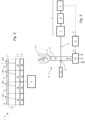
- Fig. 1 show a schematic illustration of a spectral sensor 1 according to an embodiment of the present disclosure.
- the sensor 1 is for detection of individual light-emitting particles and is a single-element multi-colour detector for use in cytometry and other fields where fluorescence events need to be distinguished in terms of colour and brightness.
- the sensor 1 comprises an array of photo-sensitive detectors 3 for detecting light emitted by the individual light-emitting particles 2.
- all individual detectors are Avalanche Photo Diodes (APDs).
- the sensor 1 further comprises a filter array 4 comprising a plurality of different band-stop filters 5.
- the filter array is arranged in the optical path to the detectors and is configured to transmit wavelengths in a detectable wavelength region to the array of photo-sensitive detectors 3.
- the detectable wavelength region is denoted ⁇ in Fig. 1 .
- Each band-stop filter 5 is associated with one or more particular photo-sensitive detectors 3. In the embodiment shown in Fig .1 , each of the detectors in the array 3 are associated with a single band-stop filter 5, i.e. there is one band-stop filter 5 over each detector of the array 3.
- the plurality of different band-stop filters 5 are further configured to reflect different wavelength intervals within said detectable wavelength region so that each photo-sensitive detector 3 of the array is configured to detect the wavelengths of the detectable wavelength region other than the reflected wavelength interval of the band-stop filter 5 being associated with the photo-sensitive detector 3.
- the photodetector 3a is associated with band stop filter 5a, which is configured to reflect wavelengths in wavelength interval ⁇ a, which is within the detectable wavelength region ⁇ but substantially smaller.
- photodetector 3b is associated with band stop filter 5b, which is configured to reflect wavelengths in wavelength interval ⁇ b, which is within the detectable wavelength region ⁇ but substantially smaller.
- Wavelength intervals ⁇ a and ⁇ b are selected so that they do not overlap.
- the detectable wavelength region ⁇ may be about between 400 and 900 nm, and ⁇ a and ⁇ b may be less than 100 nm in length.
- Each of the nine detectors of the array shown in Fig. 1 may be associated with different types of band-stop filters 5 configured to reflect wavelengths in different wavelength intervals ⁇ i.
- the different wavelength intervals ⁇ i may be selected so that they together cover the detectable wavelength region ⁇ .
- the different wavelength intervals ⁇ i may further be selected so that they do not overlap, or overlap with less than 30 nm, such as less than 20 nm, with another wavelength interval at each end point of the wavelength interval.
- the spectral sensor 1 further comprises a processing unit 6 in communication with said array of photo-sensitive detectors 3.
- a processing unit is configured for determining a spectral characteristic of an individual light-emitting particle 2 based on the response from said array of photo-sensitive detectors 3.
- the spectral characteristic that is measured may for example be the most likely fluorophore combination for each particle, which may be used for classifying a particle such as a cell.
- Determining the most likely fluorophore combination may be performed as follows:
- N 9.
- Fig. 2 shows a further embodiment of a spectral sensor 1 of the present disclosure.
- Fig. 2 is a schematic sectional view of a sensor 1 comprising an array 3 of photo-sensitive detectors 3, with individual photo-sensitive detectors 3a-d, onto which a filter array 4 comprising a plurality of different band-stop filters 5a-d are arranged.
- each detector 3a-d is associated with a single band-stop filter 5a-d.
- the band-stop filters are selected so that they reflect different wavelength intervals within the detectable wavelength region. As shown in Fig.
- band-stop filter 5a reflects wavelength interval ⁇ a
- band-stop filter 5b reflects wavelength interval ⁇ b
- band-stop filter 5c reflects wavelength interval ⁇ c
- band-stop filter 5d reflects wavelength interval ⁇ d.
- the reflected wavelength intervals ⁇ a - ⁇ d may cover unique wavelengths, or they may overlap with less than with less than 50 nm, such as less than 20 nm.
- the photo-sensitive detectors 3a-d form a continuous area in a substrate sensitive to incoming light and the different types of band-stop filters 5a-d are arranged side-by-side on the single continuous area.
- the array 4 of band-stop filters are monolithically integrated on top of the photo-sensitive detectors 3a-d.
- additional filters 7a-d built on cover glass and arranged a distance d from the array 4 of band-stop filters, as seen in the optical path of the light reaching the photo-sensitive detectors 3a-d.
- the additional filters 7a-d may be multiband filters and may be the same or different.
- the additional filters 7 may be selected to filter out light outside the detectable wavelength region of the photo-sensitive detectors 3a-d.
- the additional filters 7 may be selected to filter out excitation light used for exciting the particles or cells that are analysed in a sample.
- the combined effect of the monolithically integrated band-stop filters 5a-d and the additional filter 7 produces a cleaner and more specific transmission spectrum reaching photo-sensitive detectors 3a-d.
- the use of the additional filters 7 arranged a distance from the filter array 4 relaxes the constrains in the construction of the monolithically integrated filters.
- the additional filters 7 may be manufactured in a separate stage and it creates the opportunity to do a single production run photo-sensitive detectors 3a-d and band-stop filters and then further vary the filter specifications by selecting the correct additional filter 7.
- the senor further comprises a processing unit 6 in communication with said array of photo-sensitive detectors 3 and configured for determining a spectral characteristic of an individual light-emitting particle 2 based on the response from said array of photo-sensitive detectors 3.
- the spectral sensor 1 as disclosed in Figs. 1 and 2 is a robust, compact multicolour detector that combines a high quantum efficiency and low detector area.
- the spectral sensor 1 can be built in a monolithic fashion.
- Fig. 3 shows a schematic illustration of a flow cytometer 10 of the present disclosure.
- the flow cytometer 10 is for analysing single light emitting particles, such as cells, and may for example be used for apoptosis analysis, cyto-toxicology, cell signalling studies and analyses of ion flux and cellular pH.
- the flow cytometer 10 comprises a flow cell having a conduit 12 into which the sample to be analysed is supplied. This may be achieved by the use of a sample providing unit 15, which connects with the flow cell conduit 12 and is arranged to draw a sample from a sample tube.
- the sample may thus be a sample comprising fluorescently labelled cells 2.
- the flow cytometer 10 further comprises an exciting light source 11, which in this embodiment is a laser.
- the laser 11 is arranged so that the exciting light is focused into a portion of the flow cell 10.
- the flow cell 10 is thus positioned to receive the focused laser beams at region 16 of where fluoresced cells 2 scatter the laser beams into fluorescent light, i.e. the flow cell is arranged for receiving and flowing said sample to be analysed through the excitation light of the laser 11.
- the flow cell 10 may be part of a fluidic system arranged for flowing the supplied sample in a laminar flow past the region 16 where the laser is focused.
- the fluidic system may thus be arranged for applying a flow, such as a laminar flow, to the sample such that a stream of cells in a single line is flowed pass the focused excitation light source at the region 16 of the flow cell 10.
- the flow cytometer 10 further comprises an optical fiber 13 positioned to collect the fluorescent light from the cells at the region 16 where the laser is focused.
- the collected light is guided to a spectral sensor for detecting the light emitted by single light-emitting particles as disclosed in relation to Figs. 1 and 2 above.
- the output signals from the detectors 3 are led via an amplifier 14 to the processing unit 6, where each cell is characterized based on the determined spectral characteristic.
- the sample may comprise more than 10 000 cells and the spectral characteristic of these cells may be determined and also tabulated. Based on the determination by the processing unit 6, the cells may, after passing the excitation region 16 of the flow cell 10, be sorted into different collection vials by means of electrostatic charging and subsequent charge mediated deflection, as known in the art.
- Results from the determination of the processing unit may further be displayed in the form of distribution histograms when performing single parameter studies or as two-dimensional plots when performing multiple parameter studies.
- the flow cytometer 10 further comprises a sorting device 20 arranged downstream of the excitation region 16.
- This sorting device 20 is configured to sort the individual light emitting particles or cells 2 based on information from the processing unit 6 of the spectral sensor 1.
- the sorting device may be any type of cell sorting device as known in the art.
- the flow cytometer 10 comprises a control unit 21 configured for receiving information from the processing unit 6, as illustrated by arrow A1.
- the information may thus comprise data about the individual cell particle, such as identification data or information about the individual particle 2.
- This control unit 21 is further configured to send operational requests to trigger or actuate the sorting device 20, as illustrated by arrow A2, based on the received information from the processing unit 6.
- connection between the processing unit 6 and the sorting device 20 may also be a direct connection, i.e. the spectral sensor 1 may itself actuate the sorting device 20 without sending information to a control unit 21.
- the flow cytometer is free of the control unit 21, and there is a direct contention between sensor 1 and the sorting device 21.
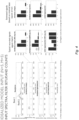
- Fig. 4 provides a simulated comparison between models for a prior art octagon detector, a multispectral band-pass filter/detector array and a multispectral notch filter/detector array of the present disclosure. It shows the spectral response of 5 fluorophores and the response of two beads that contain a limited set of those fluorophores. In addition, on the left the spectral response of a single detector from the three model systems is plotted to a broadband illumination. On the right, the simulated signals of the individual detectors are shown, assuming emission from the beads, and the estimated starting signals. It is clear that the bandpass octagon gives the largest signal per detector, as this has been designed to direct all photons to a dedicated detector.
- the multispectral bandpass filter has a similar shape, but shows less photon counts due to the distribution of the photons over the different filters.
- the multispectral notch filter set shows an inverted response, but with larger photon counts. In all cases, the starting signal was reconstructed.
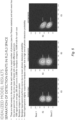
- Fig. 5 shows the resulting measurement cloud for the three modelled cases, where the two beads emit the same number of photons and are only distinguishable based on their spectral information.
- the notch multispectral filter clearly outperforms the bandpass multispectral filter due to its superior photon collection efficiency and performs similarly with the high performance bandpass octagon model.
Landscapes
- Physics & Mathematics (AREA)
- Spectroscopy & Molecular Physics (AREA)
- General Physics & Mathematics (AREA)
- Chemical & Material Sciences (AREA)
- Biochemistry (AREA)
- Analytical Chemistry (AREA)
- Life Sciences & Earth Sciences (AREA)
- General Health & Medical Sciences (AREA)
- Health & Medical Sciences (AREA)
- Immunology (AREA)
- Pathology (AREA)
- Dispersion Chemistry (AREA)
- Investigating, Analyzing Materials By Fluorescence Or Luminescence (AREA)
- Investigating Or Analysing Materials By Optical Means (AREA)
Claims (13)
- Spektralsensor (1) zum Detektieren individueller lichtemittierender Partikel (2), wobei der Sensor (2) umfassteine Anordnung von lichtempfindlichen Detektoren (3) zum Detektieren von Licht, das von den individuellen lichtemittierenden Partikeln (2) emittiert wird;eine Filteranordnung (4), die eine Vielzahl von verschiedenen Bandsperrfiltern (5) umfasst;wobei die Filteranordnung (4) dazu konfiguriert ist, Wellenlängen in einer detektierbaren Wellenlängenregion zu der Anordnung von lichtempfindlichen Detektoren (3) durchzulassen, und wobei jedes Bandsperrfilter (5) einem oder mehreren bestimmten lichtempfindlichen Detektoren (3) zugeordnet ist, und wobei die Vielzahl von verschiedenen Bandsperrfiltern (5) dazu konfiguriert ist, verschiedene Wellenlängenintervalle innerhalb der detektierbaren Wellenlängenregion zu reflektieren, so dass jeder lichtempfindliche Detektor (3) der Anordnung dazu konfiguriert ist, andere Wellenlängen der detektierbaren Wellenlängenregion als das reflektierte Wellenlängenintervall des Bandsperrfilters (5), der dem lichtempfindlichen Detektor (3) zugeordnet ist, zu detektieren, wobei jedes Bandsperrfilter (5) der Filteranordnung (4) dazu konfiguriert ist, ein Wellenlängenintervall in der detektierbaren Wellenlängenregion zu reflektieren und alle anderen Wellenlängen in der detektierbaren Wellenlängenregion durchzulassen, wobei die Vielzahl von verschiedenen Bandsperrfiltern (5) mindestens drei verschiedene Arten von Bandsperrfiltern (5) umfasst, wobei sich die reflektierten Wellenlängenintervalle der drei verschiedenen Arten von Bandsperrfiltern (5) nicht überlappen;eine Verarbeitungseinheit (6) in Kommunikation mit der Anordnung von lichtempfindlichen Detektoren (3), und dazu konfiguriert ist, ein spektrales Kennzeichen eines individuellen lichtemittierenden Partikels (2) basierend auf der Reaktion von der Anordnung von lichtempfindlichen Detektoren (3) zu bestimmen.
- Spektralsensor (1) nach Anspruch 1, wobei mindestens einer der lichtempfindlichen Detektoren (3) aus einer Lawinen-Photodiode (APD) und einem Silizium-Photovervielfacher ausgewählt ist.
- Spektralsensor (1) nach einem der vorhergehenden Ansprüche, ferner umfassend mindestens ein zusätzliches Filter (7) zum Reflektieren von Licht außerhalb der detektierbaren Wellenlängenregion, die in dem Lichtweg zu der Anordnung von lichtempfindlichen Detektoren (3) angeordnet ist.
- Spektralsensor (1) nach einem der vorhergehenden Ansprüche, wobei die Filteranordnung (4) oben auf der Anordnung von lichtempfindlichen Detektoren (3) integriert ist.
- Spektralsensor (1) nach einem der vorhergehenden Ansprüche, wobei die Verarbeitungseinheit (6) dazu konfiguriert ist, ein spektrales Kennzeichen als eine wahrscheinliche Kombination von verschiedenen lichtemittierenden Farbstoffen in dem Partikel (2) zu bestimmen.
- Spektralsensor (1) nach einem der vorhergehenden Ansprüche, wobei die Verarbeitungseinheit (6) dazu konfiguriert ist, das bestimmte spektrale Kennzeichen eines lichtemittierenden Partikels (2) mit Referenzen bekannter Arten von lichtemittierenden Partikeln (2) zu vergleichen, wodurch die Art des lichtemittierenden Partikels (2) bestimmt wird.
- Verfahren zum Detektieren von lichtemittierenden Partikeln (2) in einer fließenden Probe, umfassend folgende Schritte:a) Detektieren von emittiertem Licht von individuellen lichtemittierenden Partikeln (2) in einer fließenden Probe mit einem Spektralsensor (1) nach einem der Ansprüche 1 bis 6; undb) Bestimmen eines spektralen Kennzeichens von individuellen lichtemittierenden Partikeln (2) durch die Verarbeitungseinheit (6).
- Verfahren nach Anspruch 7, wobei die Bestimmung aus Schritt b) das Bestimmen des spektralen Kennzeichens als eine wahrscheinliche Kombination von verschiedenen lichtemittierenden Farbstoffen in den individuellen lichtemittierenden Partikeln (2) umfasst.
- Verfahren nach Anspruch 7 oder 8, ferner umfassend einen Schritt c) des Identifizierens der Art des lichtemittierenden Partikels (2) basierend auf der Bestimmung aus Schritt b).
- Verfahren nach Anspruch 7 oder 8, wobei die Identifizierung aus Schritt c) das Vergleichen des bestimmten spektralen Kennzeichens aus Schritt b) mit Referenzen bekannter Arten von lichtemittierenden Partikeln (2) umfasst, wodurch die Art des lichtemittierenden Partikels (2) identifiziert wird.
- Durchflusszytometer (10) zum Analysieren einzelner lichtemittierender Partikel (2) einer Probe; wobei das Durchflusszytometer umfasst- eine Anregungslichtquelle (11) zum Anregen der lichtemittierenden Partikel (2);- eine Durchflusszelle (12) zum Empfangen und Fließenlassen der zu analysierenden Probe durch das Anregungslicht der Anregungslichtquelle (11); und- einen Spektralsensor (1) nach einem der Ansprüche 1 bis 6 zum Detektieren des Lichts, das von einzelnen lichtemittierenden Partikeln (2) der Probe bei Anregung der Anregungslichtquelle (11) emittiert wird.
- Durchflusszytometer (10) nach Anspruch 11, ferner umfassend mindestens einen Wellenleiter (13) zum Durchlassen des Lichts, das von dem lichtemittierenden Partikel emittiert wird, zu dem Spektralsensor (1).
- Durchflusszytometer nach Anspruch 11 oder 12, ferner umfassend eine Sortiervorrichtung zum Sortieren der lichtemittierenden Partikel basierend auf Informationen von dem Spektralsensor.
Applications Claiming Priority (1)
| Application Number | Priority Date | Filing Date | Title |
|---|---|---|---|
| EP18214403 | 2018-12-20 |
Publications (2)
| Publication Number | Publication Date |
|---|---|
| EP3671148A1 EP3671148A1 (de) | 2020-06-24 |
| EP3671148B1 true EP3671148B1 (de) | 2025-01-29 |
Family
ID=64746338
Family Applications (1)
| Application Number | Title | Priority Date | Filing Date |
|---|---|---|---|
| EP19216383.0A Active EP3671148B1 (de) | 2018-12-20 | 2019-12-16 | Mehrfarbensensor für durchflusszytometrie |
Country Status (3)
| Country | Link |
|---|---|
| US (1) | US11262239B2 (de) |
| EP (1) | EP3671148B1 (de) |
| CN (1) | CN111351745B (de) |
Citations (3)
| Publication number | Priority date | Publication date | Assignee | Title |
|---|---|---|---|---|
| WO2016094654A1 (en) * | 2014-12-10 | 2016-06-16 | Cytek Biosciences Inc. | Self-triggered flow cytometer |
| US10072970B1 (en) * | 2015-12-15 | 2018-09-11 | Lockheed Martin Corporation | Hyperspectral notch filter imaging |
| US20200033192A1 (en) * | 2017-10-20 | 2020-01-30 | Charted Scientific, Inc. | Method and Apparatus of Filtering Light Using a Spectrometer Enhanced with Additional Spectral Filters with Optical Analysis of Fluorescence and Scattered Light from Particles Suspended in a Liquid Medium Using Confocal and Non Confocal Illumination and Imaging |
Family Cites Families (8)
| Publication number | Priority date | Publication date | Assignee | Title |
|---|---|---|---|---|
| CA2544418C (en) * | 2003-08-25 | 2010-05-04 | Lighthouse One Pty Ltd As Trustee Of The Lighthouse Unit Trust | Sorting apparatus and methods |
| US7202955B2 (en) * | 2004-06-30 | 2007-04-10 | Digital Optics Corporation | Spectrally diverse spectrometer and associated methods |
| US9645010B2 (en) * | 2009-03-10 | 2017-05-09 | The Regents Of The University Of California | Fluidic flow cytometry devices and methods |
| EP2293032A1 (de) | 2009-09-04 | 2011-03-09 | Radisens Diagnostic Limited | Integriertes zytometrisches Sensorsystem und Verfahren |
| CN110579435B (zh) * | 2012-10-15 | 2023-09-26 | 纳诺赛莱克特生物医药股份有限公司 | 颗粒分选的系统、设备和方法 |
| WO2015105831A1 (en) * | 2014-01-08 | 2015-07-16 | Colorado Seminary, Which Owns And Operates The University Of Denver | A wavelength dispersive microscope spectrofluorometer for characterizing multiple particles simultaneously |
| US9952133B2 (en) | 2015-10-08 | 2018-04-24 | Kinetic River Corp. | Particle analysis and sorting apparatus and methods |
| US9784685B2 (en) | 2014-12-10 | 2017-10-10 | Molecular Devices, Inc. | Liquid and plate sensors for microplate injector system |
-
2019
- 2019-12-16 EP EP19216383.0A patent/EP3671148B1/de active Active
- 2019-12-16 US US16/715,351 patent/US11262239B2/en active Active
- 2019-12-20 CN CN201911327406.XA patent/CN111351745B/zh active Active
Patent Citations (3)
| Publication number | Priority date | Publication date | Assignee | Title |
|---|---|---|---|---|
| WO2016094654A1 (en) * | 2014-12-10 | 2016-06-16 | Cytek Biosciences Inc. | Self-triggered flow cytometer |
| US10072970B1 (en) * | 2015-12-15 | 2018-09-11 | Lockheed Martin Corporation | Hyperspectral notch filter imaging |
| US20200033192A1 (en) * | 2017-10-20 | 2020-01-30 | Charted Scientific, Inc. | Method and Apparatus of Filtering Light Using a Spectrometer Enhanced with Additional Spectral Filters with Optical Analysis of Fluorescence and Scattered Light from Particles Suspended in a Liquid Medium Using Confocal and Non Confocal Illumination and Imaging |
Also Published As
| Publication number | Publication date |
|---|---|
| CN111351745B (zh) | 2023-12-19 |
| EP3671148A1 (de) | 2020-06-24 |
| CN111351745A (zh) | 2020-06-30 |
| US20200200604A1 (en) | 2020-06-25 |
| US11262239B2 (en) | 2022-03-01 |
Similar Documents
| Publication | Publication Date | Title |
|---|---|---|
| US20250334501A1 (en) | Methods of forming multi-color fluorescence-based flow cytometry panel | |
| CN110121643B (zh) | 用于流式细胞仪的光学检测系统、流式细胞仪系统及其使用方法 | |
| US20200240897A1 (en) | Optical detector for a particle sorting system | |
| US10295466B2 (en) | Fluorescence intensity correcting method, fluorescence intensity calculating method, and fluorescence intensity calculating apparatus | |
| Grégori et al. | Hyperspectral cytometry at the single‐cell level using a 32‐channel photodetector | |
| US20240151631A1 (en) | Methods for self-triggered flow-cytometers | |
| US20120156714A1 (en) | Integrated cytometric sensor system and method | |
| JPH05231938A (ja) | 高感度多波長分光装置 | |
| JP5620642B2 (ja) | 符号器付センサを用いる方法、符号器付センサ及びシステム | |
| US11727612B2 (en) | Microparticle analyzing apparatus and data displaying method | |
| US20250347613A1 (en) | Particle analysis system and particle analysis method | |
| JP2009529134A (ja) | 流体中の微細オブジェクトのフォトルミネセンス、吸光度、及び回折度を測定する装置及び方法 | |
| CN110514575B (zh) | 量子点编码微球的解码装置及方法 | |
| JP6699102B2 (ja) | 微小粒子測定装置及び情報処理方法 | |
| EP3671148B1 (de) | Mehrfarbensensor für durchflusszytometrie | |
| JP5484744B2 (ja) | 時間変化を伴う発出光の透過/反射 | |
| US20240027457A1 (en) | High parameter reagent panel and reagent kit for effective detection of aberrant cells in acute myeloid leukemia | |
| US20240210397A1 (en) | High parameter flow cytometric assay to identify human myeloid derived suppressive cells | |
| WO2024024319A1 (ja) | 生体試料分析システム、生体試料分析方法、及びプログラム | |
| WO2025028026A1 (ja) | 生体試料分析システム、分析方法、及び情報処理装置 | |
| Lawrence et al. | Polychromatic flow cytometry with an avalanche photodiode array | |
| WO2017187490A1 (ja) | 分析装置 | |
| HK1097042B (en) | Method and system for distinguishing between materials having overlapping spectra | |
| HK1097042A1 (zh) | 用於在具有重叠谱的材料之间进行辨别的方法和系统 |
Legal Events
| Date | Code | Title | Description |
|---|---|---|---|
| PUAI | Public reference made under article 153(3) epc to a published international application that has entered the european phase |
Free format text: ORIGINAL CODE: 0009012 |
|
| STAA | Information on the status of an ep patent application or granted ep patent |
Free format text: STATUS: THE APPLICATION HAS BEEN PUBLISHED |
|
| AK | Designated contracting states |
Kind code of ref document: A1 Designated state(s): AL AT BE BG CH CY CZ DE DK EE ES FI FR GB GR HR HU IE IS IT LI LT LU LV MC MK MT NL NO PL PT RO RS SE SI SK SM TR |
|
| AX | Request for extension of the european patent |
Extension state: BA ME |
|
| STAA | Information on the status of an ep patent application or granted ep patent |
Free format text: STATUS: REQUEST FOR EXAMINATION WAS MADE |
|
| 17P | Request for examination filed |
Effective date: 20201124 |
|
| RBV | Designated contracting states (corrected) |
Designated state(s): AL AT BE BG CH CY CZ DE DK EE ES FI FR GB GR HR HU IE IS IT LI LT LU LV MC MK MT NL NO PL PT RO RS SE SI SK SM TR |
|
| STAA | Information on the status of an ep patent application or granted ep patent |
Free format text: STATUS: EXAMINATION IS IN PROGRESS |
|
| 17Q | First examination report despatched |
Effective date: 20220510 |
|
| GRAP | Despatch of communication of intention to grant a patent |
Free format text: ORIGINAL CODE: EPIDOSNIGR1 |
|
| STAA | Information on the status of an ep patent application or granted ep patent |
Free format text: STATUS: GRANT OF PATENT IS INTENDED |
|
| RIC1 | Information provided on ipc code assigned before grant |
Ipc: G01J 3/12 20060101ALN20240828BHEP Ipc: G01J 3/44 20060101ALN20240828BHEP Ipc: G01N 15/14 20060101ALI20240828BHEP Ipc: G01J 3/28 20060101AFI20240828BHEP |
|
| INTG | Intention to grant announced |
Effective date: 20240905 |
|
| P01 | Opt-out of the competence of the unified patent court (upc) registered |
Free format text: CASE NUMBER: APP_58998/2024 Effective date: 20241029 |
|
| GRAS | Grant fee paid |
Free format text: ORIGINAL CODE: EPIDOSNIGR3 |
|
| GRAA | (expected) grant |
Free format text: ORIGINAL CODE: 0009210 |
|
| STAA | Information on the status of an ep patent application or granted ep patent |
Free format text: STATUS: THE PATENT HAS BEEN GRANTED |
|
| AK | Designated contracting states |
Kind code of ref document: B1 Designated state(s): AL AT BE BG CH CY CZ DE DK EE ES FI FR GB GR HR HU IE IS IT LI LT LU LV MC MK MT NL NO PL PT RO RS SE SI SK SM TR |
|
| REG | Reference to a national code |
Ref country code: GB Ref legal event code: FG4D |
|
| REG | Reference to a national code |
Ref country code: CH Ref legal event code: EP |
|
| REG | Reference to a national code |
Ref country code: DE Ref legal event code: R096 Ref document number: 602019065353 Country of ref document: DE |
|
| REG | Reference to a national code |
Ref country code: IE Ref legal event code: FG4D |
|
| REG | Reference to a national code |
Ref country code: NL Ref legal event code: MP Effective date: 20250129 |
|
| PG25 | Lapsed in a contracting state [announced via postgrant information from national office to epo] |
Ref country code: NL Free format text: LAPSE BECAUSE OF FAILURE TO SUBMIT A TRANSLATION OF THE DESCRIPTION OR TO PAY THE FEE WITHIN THE PRESCRIBED TIME-LIMIT Effective date: 20250129 |
|
| PG25 | Lapsed in a contracting state [announced via postgrant information from national office to epo] |
Ref country code: RS Free format text: LAPSE BECAUSE OF FAILURE TO SUBMIT A TRANSLATION OF THE DESCRIPTION OR TO PAY THE FEE WITHIN THE PRESCRIBED TIME-LIMIT Effective date: 20250429 |
|
| PG25 | Lapsed in a contracting state [announced via postgrant information from national office to epo] |
Ref country code: FI Free format text: LAPSE BECAUSE OF FAILURE TO SUBMIT A TRANSLATION OF THE DESCRIPTION OR TO PAY THE FEE WITHIN THE PRESCRIBED TIME-LIMIT Effective date: 20250129 |
|
| PG25 | Lapsed in a contracting state [announced via postgrant information from national office to epo] |
Ref country code: PL Free format text: LAPSE BECAUSE OF FAILURE TO SUBMIT A TRANSLATION OF THE DESCRIPTION OR TO PAY THE FEE WITHIN THE PRESCRIBED TIME-LIMIT Effective date: 20250129 |
|
| PG25 | Lapsed in a contracting state [announced via postgrant information from national office to epo] |
Ref country code: ES Free format text: LAPSE BECAUSE OF FAILURE TO SUBMIT A TRANSLATION OF THE DESCRIPTION OR TO PAY THE FEE WITHIN THE PRESCRIBED TIME-LIMIT Effective date: 20250129 |
|
| REG | Reference to a national code |
Ref country code: LT Ref legal event code: MG9D |
|
| PG25 | Lapsed in a contracting state [announced via postgrant information from national office to epo] |
Ref country code: NO Free format text: LAPSE BECAUSE OF FAILURE TO SUBMIT A TRANSLATION OF THE DESCRIPTION OR TO PAY THE FEE WITHIN THE PRESCRIBED TIME-LIMIT Effective date: 20250429 Ref country code: IS Free format text: LAPSE BECAUSE OF FAILURE TO SUBMIT A TRANSLATION OF THE DESCRIPTION OR TO PAY THE FEE WITHIN THE PRESCRIBED TIME-LIMIT Effective date: 20250529 |
|
| REG | Reference to a national code |
Ref country code: AT Ref legal event code: MK05 Ref document number: 1763871 Country of ref document: AT Kind code of ref document: T Effective date: 20250129 |
|
| PG25 | Lapsed in a contracting state [announced via postgrant information from national office to epo] |
Ref country code: HR Free format text: LAPSE BECAUSE OF FAILURE TO SUBMIT A TRANSLATION OF THE DESCRIPTION OR TO PAY THE FEE WITHIN THE PRESCRIBED TIME-LIMIT Effective date: 20250129 |
|
| PG25 | Lapsed in a contracting state [announced via postgrant information from national office to epo] |
Ref country code: PT Free format text: LAPSE BECAUSE OF FAILURE TO SUBMIT A TRANSLATION OF THE DESCRIPTION OR TO PAY THE FEE WITHIN THE PRESCRIBED TIME-LIMIT Effective date: 20250529 Ref country code: LV Free format text: LAPSE BECAUSE OF FAILURE TO SUBMIT A TRANSLATION OF THE DESCRIPTION OR TO PAY THE FEE WITHIN THE PRESCRIBED TIME-LIMIT Effective date: 20250129 |
|
| PG25 | Lapsed in a contracting state [announced via postgrant information from national office to epo] |
Ref country code: GR Free format text: LAPSE BECAUSE OF FAILURE TO SUBMIT A TRANSLATION OF THE DESCRIPTION OR TO PAY THE FEE WITHIN THE PRESCRIBED TIME-LIMIT Effective date: 20250430 Ref country code: BG Free format text: LAPSE BECAUSE OF FAILURE TO SUBMIT A TRANSLATION OF THE DESCRIPTION OR TO PAY THE FEE WITHIN THE PRESCRIBED TIME-LIMIT Effective date: 20250129 |
|
| PG25 | Lapsed in a contracting state [announced via postgrant information from national office to epo] |
Ref country code: AT Free format text: LAPSE BECAUSE OF FAILURE TO SUBMIT A TRANSLATION OF THE DESCRIPTION OR TO PAY THE FEE WITHIN THE PRESCRIBED TIME-LIMIT Effective date: 20250129 |
|
| PG25 | Lapsed in a contracting state [announced via postgrant information from national office to epo] |
Ref country code: SE Free format text: LAPSE BECAUSE OF FAILURE TO SUBMIT A TRANSLATION OF THE DESCRIPTION OR TO PAY THE FEE WITHIN THE PRESCRIBED TIME-LIMIT Effective date: 20250129 |
|
| PG25 | Lapsed in a contracting state [announced via postgrant information from national office to epo] |
Ref country code: SM Free format text: LAPSE BECAUSE OF FAILURE TO SUBMIT A TRANSLATION OF THE DESCRIPTION OR TO PAY THE FEE WITHIN THE PRESCRIBED TIME-LIMIT Effective date: 20250129 |
|
| PG25 | Lapsed in a contracting state [announced via postgrant information from national office to epo] |
Ref country code: DK Free format text: LAPSE BECAUSE OF FAILURE TO SUBMIT A TRANSLATION OF THE DESCRIPTION OR TO PAY THE FEE WITHIN THE PRESCRIBED TIME-LIMIT Effective date: 20250129 |
|
| PG25 | Lapsed in a contracting state [announced via postgrant information from national office to epo] |
Ref country code: IT Free format text: LAPSE BECAUSE OF FAILURE TO SUBMIT A TRANSLATION OF THE DESCRIPTION OR TO PAY THE FEE WITHIN THE PRESCRIBED TIME-LIMIT Effective date: 20250129 |
|
| PG25 | Lapsed in a contracting state [announced via postgrant information from national office to epo] |
Ref country code: EE Free format text: LAPSE BECAUSE OF FAILURE TO SUBMIT A TRANSLATION OF THE DESCRIPTION OR TO PAY THE FEE WITHIN THE PRESCRIBED TIME-LIMIT Effective date: 20250129 Ref country code: CZ Free format text: LAPSE BECAUSE OF FAILURE TO SUBMIT A TRANSLATION OF THE DESCRIPTION OR TO PAY THE FEE WITHIN THE PRESCRIBED TIME-LIMIT Effective date: 20250129 |
|
| PG25 | Lapsed in a contracting state [announced via postgrant information from national office to epo] |
Ref country code: RO Free format text: LAPSE BECAUSE OF FAILURE TO SUBMIT A TRANSLATION OF THE DESCRIPTION OR TO PAY THE FEE WITHIN THE PRESCRIBED TIME-LIMIT Effective date: 20250129 |
|
| PG25 | Lapsed in a contracting state [announced via postgrant information from national office to epo] |
Ref country code: SK Free format text: LAPSE BECAUSE OF FAILURE TO SUBMIT A TRANSLATION OF THE DESCRIPTION OR TO PAY THE FEE WITHIN THE PRESCRIBED TIME-LIMIT Effective date: 20250129 |
|
| REG | Reference to a national code |
Ref country code: DE Ref legal event code: R097 Ref document number: 602019065353 Country of ref document: DE |
|
| PLBE | No opposition filed within time limit |
Free format text: ORIGINAL CODE: 0009261 |
|
| STAA | Information on the status of an ep patent application or granted ep patent |
Free format text: STATUS: NO OPPOSITION FILED WITHIN TIME LIMIT |
|
| 26N | No opposition filed |
Effective date: 20251030 |
|
| PGFP | Annual fee paid to national office [announced via postgrant information from national office to epo] |
Ref country code: DE Payment date: 20251126 Year of fee payment: 7 |
|
| PGFP | Annual fee paid to national office [announced via postgrant information from national office to epo] |
Ref country code: FR Payment date: 20251119 Year of fee payment: 7 |