EP3671091A1 - Öl-kraftstoff-wärmetauscher - Google Patents
Öl-kraftstoff-wärmetauscher Download PDFInfo
- Publication number
- EP3671091A1 EP3671091A1 EP19214024.2A EP19214024A EP3671091A1 EP 3671091 A1 EP3671091 A1 EP 3671091A1 EP 19214024 A EP19214024 A EP 19214024A EP 3671091 A1 EP3671091 A1 EP 3671091A1
- Authority
- EP
- European Patent Office
- Prior art keywords
- heat exchanger
- meshes
- mesh
- fluid
- exchanger
- Prior art date
- Legal status (The legal status is an assumption and is not a legal conclusion. Google has not performed a legal analysis and makes no representation as to the accuracy of the status listed.)
- Granted
Links
Images


Classifications
-
- F—MECHANICAL ENGINEERING; LIGHTING; HEATING; WEAPONS; BLASTING
- F02—COMBUSTION ENGINES; HOT-GAS OR COMBUSTION-PRODUCT ENGINE PLANTS
- F02C—GAS-TURBINE PLANTS; AIR INTAKES FOR JET-PROPULSION PLANTS; CONTROLLING FUEL SUPPLY IN AIR-BREATHING JET-PROPULSION PLANTS
- F02C7/00—Features, components parts, details or accessories, not provided for in, or of interest apart form groups F02C1/00 - F02C6/00; Air intakes for jet-propulsion plants
- F02C7/12—Cooling of plants
- F02C7/14—Cooling of plants of fluids in the plant, e.g. lubricant or fuel
-
- F—MECHANICAL ENGINEERING; LIGHTING; HEATING; WEAPONS; BLASTING
- F28—HEAT EXCHANGE IN GENERAL
- F28D—HEAT-EXCHANGE APPARATUS, NOT PROVIDED FOR IN ANOTHER SUBCLASS, IN WHICH THE HEAT-EXCHANGE MEDIA DO NOT COME INTO DIRECT CONTACT
- F28D7/00—Heat-exchange apparatus having stationary tubular conduit assemblies for both heat-exchange media, the media being in contact with different sides of a conduit wall
- F28D7/0066—Multi-circuit heat-exchangers, e.g. integrating different heat exchange sections in the same unit or heat-exchangers for more than two fluids
- F28D7/0075—Multi-circuit heat-exchangers, e.g. integrating different heat exchange sections in the same unit or heat-exchangers for more than two fluids with particular circuits for the same heat exchange medium, e.g. with the same heat exchange medium flowing through sections having different heat exchange capacities or for heating or cooling the same heat exchange medium at different temperatures
-
- F—MECHANICAL ENGINEERING; LIGHTING; HEATING; WEAPONS; BLASTING
- F28—HEAT EXCHANGE IN GENERAL
- F28D—HEAT-EXCHANGE APPARATUS, NOT PROVIDED FOR IN ANOTHER SUBCLASS, IN WHICH THE HEAT-EXCHANGE MEDIA DO NOT COME INTO DIRECT CONTACT
- F28D7/00—Heat-exchange apparatus having stationary tubular conduit assemblies for both heat-exchange media, the media being in contact with different sides of a conduit wall
- F28D7/10—Heat-exchange apparatus having stationary tubular conduit assemblies for both heat-exchange media, the media being in contact with different sides of a conduit wall the conduits being arranged one within the other, e.g. concentrically
-
- F—MECHANICAL ENGINEERING; LIGHTING; HEATING; WEAPONS; BLASTING
- F02—COMBUSTION ENGINES; HOT-GAS OR COMBUSTION-PRODUCT ENGINE PLANTS
- F02C—GAS-TURBINE PLANTS; AIR INTAKES FOR JET-PROPULSION PLANTS; CONTROLLING FUEL SUPPLY IN AIR-BREATHING JET-PROPULSION PLANTS
- F02C7/00—Features, components parts, details or accessories, not provided for in, or of interest apart form groups F02C1/00 - F02C6/00; Air intakes for jet-propulsion plants
- F02C7/12—Cooling of plants
- F02C7/14—Cooling of plants of fluids in the plant, e.g. lubricant or fuel
- F02C7/141—Cooling of plants of fluids in the plant, e.g. lubricant or fuel of working fluid
-
- F—MECHANICAL ENGINEERING; LIGHTING; HEATING; WEAPONS; BLASTING
- F02—COMBUSTION ENGINES; HOT-GAS OR COMBUSTION-PRODUCT ENGINE PLANTS
- F02C—GAS-TURBINE PLANTS; AIR INTAKES FOR JET-PROPULSION PLANTS; CONTROLLING FUEL SUPPLY IN AIR-BREATHING JET-PROPULSION PLANTS
- F02C7/00—Features, components parts, details or accessories, not provided for in, or of interest apart form groups F02C1/00 - F02C6/00; Air intakes for jet-propulsion plants
- F02C7/22—Fuel supply systems
- F02C7/224—Heating fuel before feeding to the burner
-
- F—MECHANICAL ENGINEERING; LIGHTING; HEATING; WEAPONS; BLASTING
- F28—HEAT EXCHANGE IN GENERAL
- F28D—HEAT-EXCHANGE APPARATUS, NOT PROVIDED FOR IN ANOTHER SUBCLASS, IN WHICH THE HEAT-EXCHANGE MEDIA DO NOT COME INTO DIRECT CONTACT
- F28D7/00—Heat-exchange apparatus having stationary tubular conduit assemblies for both heat-exchange media, the media being in contact with different sides of a conduit wall
- F28D7/0041—Heat-exchange apparatus having stationary tubular conduit assemblies for both heat-exchange media, the media being in contact with different sides of a conduit wall the conduits for only one medium being tubes having parts touching each other or tubes assembled in panel form
-
- F—MECHANICAL ENGINEERING; LIGHTING; HEATING; WEAPONS; BLASTING
- F28—HEAT EXCHANGE IN GENERAL
- F28D—HEAT-EXCHANGE APPARATUS, NOT PROVIDED FOR IN ANOTHER SUBCLASS, IN WHICH THE HEAT-EXCHANGE MEDIA DO NOT COME INTO DIRECT CONTACT
- F28D7/00—Heat-exchange apparatus having stationary tubular conduit assemblies for both heat-exchange media, the media being in contact with different sides of a conduit wall
- F28D7/005—Heat-exchange apparatus having stationary tubular conduit assemblies for both heat-exchange media, the media being in contact with different sides of a conduit wall the conduits for only one medium being tubes having bent portions or being assembled from bent tubes or being tubes having a toroidal configuration
-
- F—MECHANICAL ENGINEERING; LIGHTING; HEATING; WEAPONS; BLASTING
- F28—HEAT EXCHANGE IN GENERAL
- F28D—HEAT-EXCHANGE APPARATUS, NOT PROVIDED FOR IN ANOTHER SUBCLASS, IN WHICH THE HEAT-EXCHANGE MEDIA DO NOT COME INTO DIRECT CONTACT
- F28D7/00—Heat-exchange apparatus having stationary tubular conduit assemblies for both heat-exchange media, the media being in contact with different sides of a conduit wall
- F28D7/0058—Heat-exchange apparatus having stationary tubular conduit assemblies for both heat-exchange media, the media being in contact with different sides of a conduit wall the conduits for only one medium being tubes having different orientations to each other or crossing the conduit for the other heat exchange medium
-
- F—MECHANICAL ENGINEERING; LIGHTING; HEATING; WEAPONS; BLASTING
- F28—HEAT EXCHANGE IN GENERAL
- F28D—HEAT-EXCHANGE APPARATUS, NOT PROVIDED FOR IN ANOTHER SUBCLASS, IN WHICH THE HEAT-EXCHANGE MEDIA DO NOT COME INTO DIRECT CONTACT
- F28D7/00—Heat-exchange apparatus having stationary tubular conduit assemblies for both heat-exchange media, the media being in contact with different sides of a conduit wall
- F28D7/08—Heat-exchange apparatus having stationary tubular conduit assemblies for both heat-exchange media, the media being in contact with different sides of a conduit wall the conduits being otherwise bent, e.g. in a serpentine or zig-zag
-
- F—MECHANICAL ENGINEERING; LIGHTING; HEATING; WEAPONS; BLASTING
- F28—HEAT EXCHANGE IN GENERAL
- F28F—DETAILS OF HEAT-EXCHANGE AND HEAT-TRANSFER APPARATUS, OF GENERAL APPLICATION
- F28F1/00—Tubular elements; Assemblies of tubular elements
-
- F—MECHANICAL ENGINEERING; LIGHTING; HEATING; WEAPONS; BLASTING
- F28—HEAT EXCHANGE IN GENERAL
- F28F—DETAILS OF HEAT-EXCHANGE AND HEAT-TRANSFER APPARATUS, OF GENERAL APPLICATION
- F28F27/00—Control arrangements or safety devices specially adapted for heat-exchange or heat-transfer apparatus
-
- F—MECHANICAL ENGINEERING; LIGHTING; HEATING; WEAPONS; BLASTING
- F28—HEAT EXCHANGE IN GENERAL
- F28F—DETAILS OF HEAT-EXCHANGE AND HEAT-TRANSFER APPARATUS, OF GENERAL APPLICATION
- F28F9/00—Casings; Header boxes; Auxiliary supports for elements; Auxiliary members within casings
- F28F9/001—Casings in the form of plate-like arrangements; Frames enclosing a heat exchange core
-
- F—MECHANICAL ENGINEERING; LIGHTING; HEATING; WEAPONS; BLASTING
- F05—INDEXING SCHEMES RELATING TO ENGINES OR PUMPS IN VARIOUS SUBCLASSES OF CLASSES F01-F04
- F05D—INDEXING SCHEME FOR ASPECTS RELATING TO NON-POSITIVE-DISPLACEMENT MACHINES OR ENGINES, GAS-TURBINES OR JET-PROPULSION PLANTS
- F05D2230/00—Manufacture
- F05D2230/30—Manufacture with deposition of material
- F05D2230/31—Layer deposition
-
- F—MECHANICAL ENGINEERING; LIGHTING; HEATING; WEAPONS; BLASTING
- F05—INDEXING SCHEMES RELATING TO ENGINES OR PUMPS IN VARIOUS SUBCLASSES OF CLASSES F01-F04
- F05D—INDEXING SCHEME FOR ASPECTS RELATING TO NON-POSITIVE-DISPLACEMENT MACHINES OR ENGINES, GAS-TURBINES OR JET-PROPULSION PLANTS
- F05D2260/00—Function
- F05D2260/20—Heat transfer, e.g. cooling
- F05D2260/213—Heat transfer, e.g. cooling by the provision of a heat exchanger within the cooling circuit
-
- F—MECHANICAL ENGINEERING; LIGHTING; HEATING; WEAPONS; BLASTING
- F05—INDEXING SCHEMES RELATING TO ENGINES OR PUMPS IN VARIOUS SUBCLASSES OF CLASSES F01-F04
- F05D—INDEXING SCHEME FOR ASPECTS RELATING TO NON-POSITIVE-DISPLACEMENT MACHINES OR ENGINES, GAS-TURBINES OR JET-PROPULSION PLANTS
- F05D2260/00—Function
- F05D2260/98—Lubrication
-
- F—MECHANICAL ENGINEERING; LIGHTING; HEATING; WEAPONS; BLASTING
- F28—HEAT EXCHANGE IN GENERAL
- F28D—HEAT-EXCHANGE APPARATUS, NOT PROVIDED FOR IN ANOTHER SUBCLASS, IN WHICH THE HEAT-EXCHANGE MEDIA DO NOT COME INTO DIRECT CONTACT
- F28D21/00—Heat-exchange apparatus not covered by any of the groups F28D1/00 - F28D20/00
- F28D2021/0019—Other heat exchangers for particular applications; Heat exchange systems not otherwise provided for
- F28D2021/0026—Other heat exchangers for particular applications; Heat exchange systems not otherwise provided for for combustion engines, e.g. for gas turbines or for Stirling engines
-
- F—MECHANICAL ENGINEERING; LIGHTING; HEATING; WEAPONS; BLASTING
- F28—HEAT EXCHANGE IN GENERAL
- F28F—DETAILS OF HEAT-EXCHANGE AND HEAT-TRANSFER APPARATUS, OF GENERAL APPLICATION
- F28F2210/00—Heat exchange conduits
- F28F2210/02—Heat exchange conduits with particular branching, e.g. fractal conduit arrangements
-
- F—MECHANICAL ENGINEERING; LIGHTING; HEATING; WEAPONS; BLASTING
- F28—HEAT EXCHANGE IN GENERAL
- F28F—DETAILS OF HEAT-EXCHANGE AND HEAT-TRANSFER APPARATUS, OF GENERAL APPLICATION
- F28F2250/00—Arrangements for modifying the flow of the heat exchange media, e.g. flow guiding means; Particular flow patterns
- F28F2250/06—Derivation channels, e.g. bypass
-
- Y—GENERAL TAGGING OF NEW TECHNOLOGICAL DEVELOPMENTS; GENERAL TAGGING OF CROSS-SECTIONAL TECHNOLOGIES SPANNING OVER SEVERAL SECTIONS OF THE IPC; TECHNICAL SUBJECTS COVERED BY FORMER USPC CROSS-REFERENCE ART COLLECTIONS [XRACs] AND DIGESTS
- Y02—TECHNOLOGIES OR APPLICATIONS FOR MITIGATION OR ADAPTATION AGAINST CLIMATE CHANGE
- Y02T—CLIMATE CHANGE MITIGATION TECHNOLOGIES RELATED TO TRANSPORTATION
- Y02T50/00—Aeronautics or air transport
- Y02T50/60—Efficient propulsion technologies, e.g. for aircraft
Definitions
- the invention relates to the field of turbomachine heat exchangers. More specifically, the invention provides an oil / fuel heat exchanger for a turbomachine. The invention also relates to an axial turbomachine, in particular a turbojet. The invention further provides a method of making a heat exchanger.
- the document US 2018/0057942 A1 discloses an aircraft oil / fuel exchanger, obtained by additive manufacturing, comprising a group of parallel rectilinear channels formed between two manifolds.
- the fuel circulates in these channels and is heated by oil which circulates in a cavity delimited by guide walls and a cylindrical wall.
- the known exchanger does not allow a homogeneous distribution of the fuel circulating in the channels. This implies that the heat exchange potential is not fully exploited in all areas of the cavity.
- the invention aims to solve at least one of the problems posed by the prior art.
- the invention aims to optimize the heat exchange, the pressure drops, and possibly the operation of a turbomachine.
- the invention also aims to provide a simple and compact solution, easy to produce and convenient to maintain.
- the subject of the invention is a heat exchanger between a first fluid and a second fluid, in particular a turbomachine heat exchanger, the heat exchanger comprising: a reference direction; and a network of tubular meshes delimiting an interior passage for the first fluid, the network of meshes comprising a multitude of meshes, each of the meshes, being formed, successively in the reference direction, of at least two curvilinear ramifications, called anterior, a junction where the two anterior ramifications meet, and at least two curvilinear ramifications, called posterior, separating from the junction; remarkable in that the multitude of meshes comprises at least a first mesh, at least one anterior ramification of the first mesh being connected to at least one posterior ramification of a second mesh and at least one other anterior ramification of the first mesh being connected at least one posterior ramification of a third mesh, distinct from the second mesh;
- the invention also relates to an aircraft turbojet engine comprising bearings and in particular a transmission driving a fan, and the heat exchanger according to the invention.
- the invention may alternatively or in addition have for its object a remarkable exchanger in that the multitude of meshes comprises at least one mesh of which all the anterior ramifications except at least one are connected to posterior ramifications of another mesh.
- the invention may alternatively or in addition have for its object a remarkable exchanger in that the multitude of meshes comprises stages of meshes arranged successively in the reference direction, each junction of the meshes of a given stage being offset (optionally in staggered rows) relative to the junctions of the adjacent storey, in a direction perpendicular to the reference direction.
- the subject of the invention may be a heat exchanger between a first fluid and a second fluid, in particular a turbomachine heat exchanger, the heat exchanger comprising: a reference direction and a network of tubular meshes in which crosses the first fluid, at least part of the external surface of the network being in contact with the second fluid, the network comprising several meshes stacking at least in the reference direction, each mesh comprising tubular branches, curvilinear and connected to a common junction occupying a central position of the mesh in question, among which a first mesh and a second mesh are stacked in the reference direction, the first mesh comprising: a first plane perpendicular to the reference direction and passing through the center of the first stitch; at least two so-called posterior ramifications lying on the side of the plane oriented in the reference direction; at least two so-called earlier ramifications lying on the other side of said plane; the second mesh comprising: a second reference plane perpendicular to the reference direction and passing through the center of the second mesh; at least two
- each object of the invention is also applicable to the other objects of the invention.
- each object of the invention can be combined with the other objects.
- the objects of the invention can also be combined with the embodiments of the description, which in addition can be combined with one another.
- the proposed solution is a compact, light and efficient solution in terms of heat exchange.
- the particular structure of the tubular mesh network allowing a redistribution of the fluid guarantees that all the zones of the heat exchanger, even the most eccentric zones, have an optimal heat exchange.
- This solution makes it possible to reduce the size and therefore the weight of the exchanger, while keeping the same efficiency.
- the shape of the curved pipes and the repetition of crossover zones between the tubes promote turbulence and therefore improve heat transfer.
- the network of tubular meshes forms a self-supporting structure facilitating the design of the assembly.
- the presence of a central bypass avoids the risk of clogging of the exchanger in extreme cold.
- the exchanger is a single piece eliminating the risk of leakage while guaranteeing very good resistance to forces.
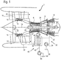
- the figure 1 shows in simplified fashion an axial turbomachine 2.
- the turbojet engine 2 comprises a first compressor, low pressure 4 and a second compressor, high pressure 6, a combustion chamber 8 and one or more turbines 10.
- the mechanical power of the turbine 10 transmitted to the rotor 12 sets in motion the two compressors 4 and 6.
- the latter comprise several rows of rotor blades associated with rows of stator blades. The rotation of the rotor around its axis of rotation 14 thus makes it possible to generate an air flow and to compress it progressively until the inlet of the combustion chamber 8.
- a blower 16 is coupled to the rotor 12 and generates an air flow which is divided into a primary flow 18 and into a secondary flow 20 passing through an annular duct (partially shown) along the machine and then joining the primary flow at the outlet. turbine.
- Reduction means such as a planetary reduction gear 22, can reduce the speed of rotation of the blower and / or of the low-pressure compressor relative to the associated turbine.
- the secondary flow can be accelerated so as to generate a thrust reaction necessary for the flight of an aircraft.
- the rotor 12 comprises a transmission shaft 24 mounted on the casing by means of two bearings 26.
- a lubrication circuit 30 is provided.
- This circuit 30 comprises conduits 32 for transporting the oil to the organs of the turbojet engine requiring it, such as in particular the gearbox 22 and the bearings 26.
- the circuit 30 for this purpose comprises a pump 34 for setting the oil in motion. the circuit 30 and a reservoir 36.
- the oil return conduits of the members and their associated delivery pumps are not shown.
- the figure 1 also shows a fuel circuit 40, provided with conduits 42, a low pressure pump 44, a high pressure pump 48 and a tank 46, for example housed in a wing.
- a heat exchanger 50 (FCOC: acronym for Fuel Cooled Oil Cooler) is provided to regulate the temperature of the oil in circuit 32.
- FCOC acronym for Fuel Cooled Oil Cooler
- the oil ensuring the lubrication of bearings 22, 26 and 26 is heated and must be cooled .
- the use of fuel stored in the wings which is cold at high altitude makes it possible to cool the oil advantageously.
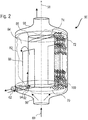
- the figure 2 illustrates the heat exchanger according to an embodiment of the invention.
- the heat exchanger 50 comprises a heat exchanger matrix constituted by a network of tubular meshes 100 disposed between two partitions 70, 72 into which the passages formed by the network of tubular meshes 100 open.
- the network of tubular meshes 100 guides a first fluid 60 (for example fuel) from an inlet manifold 96 to an outlet manifold 98.
- the network of tubular meshes 100 consists of a stack of meshes mounted in staggered rows. Each mesh has ramifications in the form of curvilinear tubes emanating from a common junction.
- the network of tubular meshes 100 has a set of passages which separate and join while ensuring a redistribution of the fluid between them. A given entity of fluid can therefore pass from one mesh to another while moving radially and / or circumferentially relative to the center of the exchanger.
- the network of tubular meshes 100 can comply with symmetry rules or not.
- the heat exchanger 50 may comprise a body provided with a side wall 82 surrounding the network of tubular meshes 100, the internal surface of the side wall 82 and the two partitions 70, 72 partially delimiting a cavity 84 in which a second fluid 62 (for example oil).
- the side wall 82 of the heat exchanger 50 may have a substantially cylindrical shape, with a diameter preferably between 7 and 25 cm, and a height preferably between 10 and 60 cm, the axis of the cylinder being aligned with the reference direction 58.
- the exchanger 50 may comprise a bypass channel 86 for the first fluid 60 in bypass of the network of tubular meshes 100, the bypass channel 86 being formed in a central position of the exchanger 50, the channel bypass 86 being substantially aligned with the reference direction 58.
- the diameter of the bypass channel 86 can be between 30 and 60% of the diameter of the body. The presence of the bypass channel 86 makes it possible to stiffen the structure and ensures better maintenance of the network of tubular meshes 100.
- the exchanger 50 can be parallel current and / or counter-current. In the example illustrated, it is both parallel current in one part of the exchanger and counter-current in another part of the exchanger.
- a guide element 88 is provided for guiding the second fluid 62 in a part of the cavity 84 in a reference flow direction substantially parallel to the reference direction 58 over at least a majority of the height of the body.
- the guide element 88 guides the second fluid 62 in another part of the cavity over at least a majority of the height of the body in a direction opposite to the reference flow direction, the direction being substantially parallel to the reference direction 58.
- the guide element 88 may comprise at least one partition wall extending in part in a plane parallel to the reference direction 58 between the two partitions 70, 72.
- the guide element 88 in the figure 2 allows a single round trip of the second fluid 62. It is understood that a guide element 88 can be designed to allow several back and forth, and this by varying the number of guide walls disposed in the cavity 84. L advantage of this design is to present an input and an output of the exchanger for the second fluid which are close to one another. In an alternative design with only parallel current or only against current, the inlet and the outlet of the exchanger are spaced from each other along the reference axis 58.
- the circuit of the first fluid can comprise a valve 74 of the discharge and / or thermostatic type added in the bypass channel 86.
- the exchanger can comprise a bypass pass 92 for the second fluid integrated in the body of the heat exchanger 50.
- the bypass bypass 92 is formed in the lower part of the partition wall serving as a guide element 88.
- the bypass channel 92 can be produced in a module integral with the wall 82 of the body of the heat exchanger 50, the module possibly having come in one piece with the wall of the heat exchanger 50.
- a valve 94 of the discharge and / or thermostatic type can be attached to the bypass channel 92.
- the figure 3 shows another embodiment of the invention in which the mesh 103 which serves as the basic pattern for the network of tubular meshes 100 comprises four branches arranged in a plane, of which, successively following the orientation 58, two anterior branches 103.1, one junction 103.2 and two posterior ramifications 103.3.
- This basic pattern can be stacked so as to form a flat or curved sheet of tubes (not shown).
- the meshes 103 of an upper layer are pivoted for example 90 degrees relative to the meshes 103 of the lower layer. This second structure allows better three-dimensional redistribution of the fluid.
- the figure 4 presents an embodiment of meshes 104 with four ramifications in which the two posterior ramifications are arranged in a plane which is secant with respect to the anterior ramifications.
- the figure 5 illustrates an embodiment of stitches 105 with five ramifications with two posterior ramifications and the three anterior ramifications. This configuration is asymmetrical.
- the figure 6 represents another embodiment of meshes 106 with six ramifications with rotational symmetry.
- the previous ramifications or posterior can be distributed regularly, with an angle of about 120 degrees between the planes in which the ramifications are inscribed.
- the figure 7 shows an embodiment of meshes 107 with six ramifications with specular symmetry.
- the anterior or posterior ramifications can be distributed regularly, with an angle of approximately 120 degrees between the planes in which the ramifications are inscribed.
- the figure 8 illustrates an embodiment of stitches 108 with eight ramifications with specular symmetry.
- the anterior or posterior ramifications can be distributed regularly, with an angle of approximately 90 degrees between the planes in which the ramifications are inscribed.
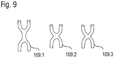
- the figure 9 shows a junction 109.1 comprising an intermediate tube.
- the cross section of the internal passage is substantially equal to half the sum of the cross sections of each branch. This configuration gives rise to pressure drops which may be desired to slow down a flow rate.
- the meshes 109.2 and 109.3 can be designed so that the posterior ramifications are joined directly to the anterior ramifications forming a chamber at the junction 103.2.
- the chamber improves the mechanical resistance of the assembly by the effect of hollow bodies.
- the junction of the 109.2 mesh includes a rounding to improve the resistance of the structure.
- a teardrop shape - seen in a plane parallel to the reference direction - can facilitate the production by additive manufacturing because it is not necessary to provide reinforcements during manufacturing.
- the junction of mesh 109.3 includes sharp angles to avoid stagnation of the fluid and reduce pressure losses.
- a shape with sharp angles such as a triangle or a pentagon - seen in a plane parallel to the reference direction - facilitates production by additive manufacturing since it is not necessary to provide reinforcements.
- the branch section can be circular.
- Other section shapes square, triangular, rectangular, elliptical
- the three embodiments of the junction according to meshes 109.1, 109.2 and 109.3 respectively can be combined with the mesh variants according to the figures 3 to 8 .
- the meshes 103, 104, 105, 106, 107, 108, 109.1, 109.2, 109.3 can be stacked according to any suitable arrangement, in particular according to the directions associated with the cylindrical or Cartesian coordinates.
- the complexity of the structure of the mesh network could not be obtained by conventional manufacturing means and is therefore produced, according to the invention, by additive manufacturing, from powder, possibly made of titanium or aluminum.
- the thickness of the layers can be between 20 ⁇ m and 50 ⁇ m, which makes it possible to achieve a thickness of the tubes forming the meshes of the order of 0.4 to 0.6 mm, and of partitions of 0.60 mm .
- the use of the matrix and the exchanger according to the invention for fuel and oil is not limited to this example.
Landscapes
- Engineering & Computer Science (AREA)
- Mechanical Engineering (AREA)
- General Engineering & Computer Science (AREA)
- Physics & Mathematics (AREA)
- Thermal Sciences (AREA)
- Chemical & Material Sciences (AREA)
- Combustion & Propulsion (AREA)
- Heat-Exchange Devices With Radiators And Conduit Assemblies (AREA)
Applications Claiming Priority (1)
| Application Number | Priority Date | Filing Date | Title |
|---|---|---|---|
| BE20185931A BE1026909B1 (fr) | 2018-12-21 | 2018-12-21 | Échangeur de chaleur huile carburant |
Publications (2)
| Publication Number | Publication Date |
|---|---|
| EP3671091A1 true EP3671091A1 (de) | 2020-06-24 |
| EP3671091B1 EP3671091B1 (de) | 2025-08-13 |
Family
ID=65041510
Family Applications (1)
| Application Number | Title | Priority Date | Filing Date |
|---|---|---|---|
| EP19214024.2A Active EP3671091B1 (de) | 2018-12-21 | 2019-12-06 | Öl-kraftstoff-wärmetauscher |
Country Status (4)
| Country | Link |
|---|---|
| US (3) | US11181322B2 (de) |
| EP (1) | EP3671091B1 (de) |
| CN (1) | CN111351378B (de) |
| BE (1) | BE1026909B1 (de) |
Cited By (1)
| Publication number | Priority date | Publication date | Assignee | Title |
|---|---|---|---|---|
| FR3151081A1 (fr) * | 2023-07-11 | 2025-01-17 | Freyssinet Aero Group | Garnissage filaire pour un appareil d’échange gaz-liquide à capacité de transfert thermique radiale |
Families Citing this family (8)
| Publication number | Priority date | Publication date | Assignee | Title |
|---|---|---|---|---|
| US11725881B2 (en) * | 2021-04-20 | 2023-08-15 | Transportation Ip Holdings, Llc | Core body for transfer apparatus |
| US12398960B2 (en) * | 2021-04-20 | 2025-08-26 | Transportation Ip Holdings, Llc | Core body for transfer apparatus |
| CN113720193B (zh) * | 2021-08-12 | 2022-06-07 | 西安交通大学 | 面向增材制造的肺泡仿生超级换热器结构及其制备方法 |
| US12550298B2 (en) * | 2021-11-15 | 2026-02-10 | Ricoh Company, Lid. | Heat sink and method of manufacturing same, heat exchanger, and gyroid structure component and method of manufacturing same |
| US20240254919A1 (en) * | 2023-01-26 | 2024-08-01 | Raytheon Technologies Corporation | Lattice heat exchanger |
| US12460558B2 (en) * | 2024-04-29 | 2025-11-04 | Pratt & Whitney Canada Corp. | Heat exchanger having a mixing chamber and protrusions |
| US20250334357A1 (en) * | 2024-04-29 | 2025-10-30 | Pratt & Whitney Canada Corp. | Heat exchanger having a mixing chamber with convergent section |
| US20250334358A1 (en) * | 2024-04-29 | 2025-10-30 | Pratt & Whitney Canada Corp. | Heat exchanger having a mixing chamber with fins |
Citations (5)
| Publication number | Priority date | Publication date | Assignee | Title |
|---|---|---|---|---|
| EP2775244A1 (de) * | 2013-03-05 | 2014-09-10 | The Boeing Company | Mikrogitter-Querstromwärmetauscher für Flugzeuge |
| US20180057942A1 (en) | 2016-08-31 | 2018-03-01 | Unison Industries, Llc | Methods for manufacturing a heat exchanger |
| US9976815B1 (en) | 2014-02-20 | 2018-05-22 | Hrl Laboratories, Llc | Heat exchangers made from additively manufactured sacrificial templates |
| US20180187984A1 (en) | 2017-01-03 | 2018-07-05 | Titan Tensor LLC | Monolithic Bicontinuous Labyrinth Structures and Methods For Their Manufacture |
| US20180297843A1 (en) * | 2017-04-17 | 2018-10-18 | Honeywell International Inc. | Cell structures for use in heat exchangers, and methods of producing the same |
Family Cites Families (18)
| Publication number | Priority date | Publication date | Assignee | Title |
|---|---|---|---|---|
| US4991643A (en) * | 1989-08-23 | 1991-02-12 | Hayden, Inc. | Heat exchanger with internal bypass valve |
| DE4139104C1 (de) * | 1991-11-28 | 1993-05-27 | Mtu Muenchen Gmbh | |
| US5427174A (en) * | 1993-04-30 | 1995-06-27 | Heat Transfer Devices, Inc. | Method and apparatus for a self contained heat exchanger |
| CA2454252A1 (en) * | 2001-07-13 | 2003-01-23 | Coolit Systems Inc. | Cooling apparatus for electronic devices |
| JP2007010199A (ja) * | 2005-06-29 | 2007-01-18 | Calsonic Kansei Corp | 多孔管及び多孔管の製造方法 |
| CN101464099A (zh) * | 2007-12-18 | 2009-06-24 | 高汉光 | 一种空压机余热自动采集换热器 |
| CN101419031B (zh) * | 2008-11-17 | 2010-06-02 | 杨正清 | 高温炉渣省煤器 |
| KR101125004B1 (ko) * | 2009-12-04 | 2012-03-27 | 기아자동차주식회사 | 냉각수 및 오일 통합 열교환형 배기열 회수장치 |
| DE102012216452A1 (de) * | 2012-09-14 | 2014-03-20 | Eberspächer Exhaust Technology GmbH & Co. KG | Wärmeübertrager |
| CN103047883A (zh) * | 2013-01-11 | 2013-04-17 | 哈尔滨工程大学 | 波浪管方形管壳式换热器 |
| US11162424B2 (en) * | 2013-10-11 | 2021-11-02 | Reaction Engines Ltd | Heat exchangers |
| CN104073268A (zh) * | 2014-07-11 | 2014-10-01 | 上海理工大学 | 防止结焦的导热油焦炉荒煤气余热回收装置 |
| GB201419963D0 (en) * | 2014-11-10 | 2014-12-24 | Rolls Royce Plc | Heat exchanger |
| CN204739934U (zh) * | 2015-05-29 | 2015-11-04 | 中国石油化工股份有限公司 | 列管式换热器和费托合成浆态床反应器 |
| US10843267B2 (en) * | 2017-03-03 | 2020-11-24 | Regents Of The University Of Minnesota | Additively manufactured heat exchangers |
| US10406601B2 (en) * | 2017-05-30 | 2019-09-10 | Caterpillar Inc. | 3D printed heat exchanger |
| CN107255425B (zh) * | 2017-06-27 | 2020-05-05 | 中国船舶重工集团公司第七一九研究所 | 一种换热板、加工方法及换热器 |
| CN207991335U (zh) * | 2017-12-29 | 2018-10-19 | 无锡鑫盛换热器科技股份有限公司 | 一种带有旁通管结构的新型换热器 |
-
2018
- 2018-12-21 BE BE20185931A patent/BE1026909B1/fr active IP Right Grant
-
2019
- 2019-12-06 EP EP19214024.2A patent/EP3671091B1/de active Active
- 2019-12-18 US US16/719,571 patent/US11181322B2/en active Active
- 2019-12-23 CN CN201911335135.2A patent/CN111351378B/zh active Active
-
2021
- 2021-11-22 US US17/531,987 patent/US11662151B2/en active Active
- 2021-11-22 US US17/531,906 patent/US11656030B2/en active Active
Patent Citations (5)
| Publication number | Priority date | Publication date | Assignee | Title |
|---|---|---|---|---|
| EP2775244A1 (de) * | 2013-03-05 | 2014-09-10 | The Boeing Company | Mikrogitter-Querstromwärmetauscher für Flugzeuge |
| US9976815B1 (en) | 2014-02-20 | 2018-05-22 | Hrl Laboratories, Llc | Heat exchangers made from additively manufactured sacrificial templates |
| US20180057942A1 (en) | 2016-08-31 | 2018-03-01 | Unison Industries, Llc | Methods for manufacturing a heat exchanger |
| US20180187984A1 (en) | 2017-01-03 | 2018-07-05 | Titan Tensor LLC | Monolithic Bicontinuous Labyrinth Structures and Methods For Their Manufacture |
| US20180297843A1 (en) * | 2017-04-17 | 2018-10-18 | Honeywell International Inc. | Cell structures for use in heat exchangers, and methods of producing the same |
Cited By (1)
| Publication number | Priority date | Publication date | Assignee | Title |
|---|---|---|---|---|
| FR3151081A1 (fr) * | 2023-07-11 | 2025-01-17 | Freyssinet Aero Group | Garnissage filaire pour un appareil d’échange gaz-liquide à capacité de transfert thermique radiale |
Also Published As
| Publication number | Publication date |
|---|---|
| US11662151B2 (en) | 2023-05-30 |
| EP3671091B1 (de) | 2025-08-13 |
| US11181322B2 (en) | 2021-11-23 |
| CN111351378A (zh) | 2020-06-30 |
| US11656030B2 (en) | 2023-05-23 |
| US20220082332A1 (en) | 2022-03-17 |
| BE1026909B1 (fr) | 2020-07-22 |
| BE1026909A1 (fr) | 2020-07-14 |
| US20220082331A1 (en) | 2022-03-17 |
| CN111351378B (zh) | 2024-12-31 |
| US20200200482A1 (en) | 2020-06-25 |
Similar Documents
| Publication | Publication Date | Title |
|---|---|---|
| EP3671091B1 (de) | Öl-kraftstoff-wärmetauscher | |
| BE1026232B1 (fr) | Système hydraulique | |
| BE1026919B1 (fr) | Échangeur de chaleur air-huile | |
| EP3735518B1 (de) | Turbinentriebwerk mit wärmetauscher im bypasskanal | |
| EP3696389B1 (de) | Luft-öl-wärmetauscher | |
| EP3519753B1 (de) | Matrix für einen luft-öl-wärmetauscher eines strahltriebwerks | |
| EP3615780B1 (de) | Flugzeugantriebsanordnung mit luft-flüssigkeit-wärmetauschern | |
| FR3034474A1 (fr) | Turbomachine equipee d'un secteur d'aubage et d'un circuit de refroidissement | |
| EP3548706A1 (de) | Austrittsleitschaufel einer turbomaschine eines flugzeugs mit einem gebogenen schmierkanal mit verbessertem design | |
| EP3623606B1 (de) | Multi-fluid-matrix eines wärmetauschers | |
| WO2022129785A1 (fr) | Échangeur de chaleur à plaques comportant des éléments profilés de guidage | |
| EP4374047B1 (de) | Turbinentriebwerk für ein flugzeug mit wärmetauscher | |
| EP4374046B1 (de) | Turbinentriebwerk für ein flugzeug mit wärmetauscher | |
| BE1026074A1 (fr) | Groupe de lubrification à crépine pour turbomachine | |
| WO2026062345A1 (fr) | Système d'échangeur de chaleur pour une turbomachine d'aéronef et ensemble comportant un tel système |
Legal Events
| Date | Code | Title | Description |
|---|---|---|---|
| PUAI | Public reference made under article 153(3) epc to a published international application that has entered the european phase |
Free format text: ORIGINAL CODE: 0009012 |
|
| STAA | Information on the status of an ep patent application or granted ep patent |
Free format text: STATUS: THE APPLICATION HAS BEEN PUBLISHED |
|
| AK | Designated contracting states |
Kind code of ref document: A1 Designated state(s): AL AT BE BG CH CY CZ DE DK EE ES FI FR GB GR HR HU IE IS IT LI LT LU LV MC MK MT NL NO PL PT RO RS SE SI SK SM TR |
|
| AX | Request for extension of the european patent |
Extension state: BA ME |
|
| STAA | Information on the status of an ep patent application or granted ep patent |
Free format text: STATUS: REQUEST FOR EXAMINATION WAS MADE |
|
| 17P | Request for examination filed |
Effective date: 20201221 |
|
| RBV | Designated contracting states (corrected) |
Designated state(s): AL AT BE BG CH CY CZ DE DK EE ES FI FR GB GR HR HU IE IS IT LI LT LU LV MC MK MT NL NO PL PT RO RS SE SI SK SM TR |
|
| STAA | Information on the status of an ep patent application or granted ep patent |
Free format text: STATUS: EXAMINATION IS IN PROGRESS |
|
| 17Q | First examination report despatched |
Effective date: 20220630 |
|
| GRAP | Despatch of communication of intention to grant a patent |
Free format text: ORIGINAL CODE: EPIDOSNIGR1 |
|
| STAA | Information on the status of an ep patent application or granted ep patent |
Free format text: STATUS: GRANT OF PATENT IS INTENDED |
|
| INTG | Intention to grant announced |
Effective date: 20250305 |
|
| GRAS | Grant fee paid |
Free format text: ORIGINAL CODE: EPIDOSNIGR3 |
|
| GRAA | (expected) grant |
Free format text: ORIGINAL CODE: 0009210 |
|
| STAA | Information on the status of an ep patent application or granted ep patent |
Free format text: STATUS: THE PATENT HAS BEEN GRANTED |
|
| AK | Designated contracting states |
Kind code of ref document: B1 Designated state(s): AL AT BE BG CH CY CZ DE DK EE ES FI FR GB GR HR HU IE IS IT LI LT LU LV MC MK MT NL NO PL PT RO RS SE SI SK SM TR |
|
| REG | Reference to a national code |
Ref country code: GB Ref legal event code: FG4D Free format text: NOT ENGLISH |
|
| REG | Reference to a national code |
Ref country code: CH Ref legal event code: EP |
|
| REG | Reference to a national code |
Ref country code: DE Ref legal event code: R096 Ref document number: 602019073997 Country of ref document: DE |
|
| REG | Reference to a national code |
Ref country code: IE Ref legal event code: FG4D Free format text: LANGUAGE OF EP DOCUMENT: FRENCH |
|
| REG | Reference to a national code |
Ref country code: NL Ref legal event code: MP Effective date: 20250813 |
|
| PG25 | Lapsed in a contracting state [announced via postgrant information from national office to epo] |
Ref country code: IS Free format text: LAPSE BECAUSE OF FAILURE TO SUBMIT A TRANSLATION OF THE DESCRIPTION OR TO PAY THE FEE WITHIN THE PRESCRIBED TIME-LIMIT Effective date: 20251213 |
|
| PGFP | Annual fee paid to national office [announced via postgrant information from national office to epo] |
Ref country code: GB Payment date: 20251229 Year of fee payment: 7 |
|
| PG25 | Lapsed in a contracting state [announced via postgrant information from national office to epo] |
Ref country code: NO Free format text: LAPSE BECAUSE OF FAILURE TO SUBMIT A TRANSLATION OF THE DESCRIPTION OR TO PAY THE FEE WITHIN THE PRESCRIBED TIME-LIMIT Effective date: 20251113 |
|
| REG | Reference to a national code |
Ref country code: LT Ref legal event code: MG9D |
|
| PG25 | Lapsed in a contracting state [announced via postgrant information from national office to epo] |
Ref country code: PT Free format text: LAPSE BECAUSE OF FAILURE TO SUBMIT A TRANSLATION OF THE DESCRIPTION OR TO PAY THE FEE WITHIN THE PRESCRIBED TIME-LIMIT Effective date: 20251215 |
|
| PG25 | Lapsed in a contracting state [announced via postgrant information from national office to epo] |
Ref country code: FI Free format text: LAPSE BECAUSE OF FAILURE TO SUBMIT A TRANSLATION OF THE DESCRIPTION OR TO PAY THE FEE WITHIN THE PRESCRIBED TIME-LIMIT Effective date: 20250813 |
|
| PG25 | Lapsed in a contracting state [announced via postgrant information from national office to epo] |
Ref country code: NL Free format text: LAPSE BECAUSE OF FAILURE TO SUBMIT A TRANSLATION OF THE DESCRIPTION OR TO PAY THE FEE WITHIN THE PRESCRIBED TIME-LIMIT Effective date: 20250813 Ref country code: HR Free format text: LAPSE BECAUSE OF FAILURE TO SUBMIT A TRANSLATION OF THE DESCRIPTION OR TO PAY THE FEE WITHIN THE PRESCRIBED TIME-LIMIT Effective date: 20250813 |
|
| PGFP | Annual fee paid to national office [announced via postgrant information from national office to epo] |
Ref country code: FR Payment date: 20251222 Year of fee payment: 7 |
|
| PG25 | Lapsed in a contracting state [announced via postgrant information from national office to epo] |
Ref country code: GR Free format text: LAPSE BECAUSE OF FAILURE TO SUBMIT A TRANSLATION OF THE DESCRIPTION OR TO PAY THE FEE WITHIN THE PRESCRIBED TIME-LIMIT Effective date: 20251114 |
|
| PGFP | Annual fee paid to national office [announced via postgrant information from national office to epo] |
Ref country code: BE Payment date: 20251224 Year of fee payment: 7 |
|
| PG25 | Lapsed in a contracting state [announced via postgrant information from national office to epo] |
Ref country code: SE Free format text: LAPSE BECAUSE OF FAILURE TO SUBMIT A TRANSLATION OF THE DESCRIPTION OR TO PAY THE FEE WITHIN THE PRESCRIBED TIME-LIMIT Effective date: 20250813 |
|
| PG25 | Lapsed in a contracting state [announced via postgrant information from national office to epo] |
Ref country code: LV Free format text: LAPSE BECAUSE OF FAILURE TO SUBMIT A TRANSLATION OF THE DESCRIPTION OR TO PAY THE FEE WITHIN THE PRESCRIBED TIME-LIMIT Effective date: 20250813 |
|
| PG25 | Lapsed in a contracting state [announced via postgrant information from national office to epo] |
Ref country code: PL Free format text: LAPSE BECAUSE OF FAILURE TO SUBMIT A TRANSLATION OF THE DESCRIPTION OR TO PAY THE FEE WITHIN THE PRESCRIBED TIME-LIMIT Effective date: 20250813 Ref country code: BG Free format text: LAPSE BECAUSE OF FAILURE TO SUBMIT A TRANSLATION OF THE DESCRIPTION OR TO PAY THE FEE WITHIN THE PRESCRIBED TIME-LIMIT Effective date: 20250813 |
|
| PG25 | Lapsed in a contracting state [announced via postgrant information from national office to epo] |
Ref country code: RS Free format text: LAPSE BECAUSE OF FAILURE TO SUBMIT A TRANSLATION OF THE DESCRIPTION OR TO PAY THE FEE WITHIN THE PRESCRIBED TIME-LIMIT Effective date: 20251113 |
|
| PG25 | Lapsed in a contracting state [announced via postgrant information from national office to epo] |
Ref country code: ES Free format text: LAPSE BECAUSE OF FAILURE TO SUBMIT A TRANSLATION OF THE DESCRIPTION OR TO PAY THE FEE WITHIN THE PRESCRIBED TIME-LIMIT Effective date: 20250813 |
|
| REG | Reference to a national code |
Ref country code: AT Ref legal event code: MK05 Ref document number: 1825054 Country of ref document: AT Kind code of ref document: T Effective date: 20250813 |
|
| PG25 | Lapsed in a contracting state [announced via postgrant information from national office to epo] |
Ref country code: RO Free format text: LAPSE BECAUSE OF FAILURE TO SUBMIT A TRANSLATION OF THE DESCRIPTION OR TO PAY THE FEE WITHIN THE PRESCRIBED TIME-LIMIT Effective date: 20250813 |