EP4374046B1 - Turbinentriebwerk für ein flugzeug mit wärmetauscher - Google Patents
Turbinentriebwerk für ein flugzeug mit wärmetauscher Download PDFInfo
- Publication number
- EP4374046B1 EP4374046B1 EP21754931.0A EP21754931A EP4374046B1 EP 4374046 B1 EP4374046 B1 EP 4374046B1 EP 21754931 A EP21754931 A EP 21754931A EP 4374046 B1 EP4374046 B1 EP 4374046B1
- Authority
- EP
- European Patent Office
- Prior art keywords
- vanes
- turbomachine
- fin
- extrados
- intrados
- Prior art date
- Legal status (The legal status is an assumption and is not a legal conclusion. Google has not performed a legal analysis and makes no representation as to the accuracy of the status listed.)
- Active
Links
Images


Classifications
-
- F—MECHANICAL ENGINEERING; LIGHTING; HEATING; WEAPONS; BLASTING
- F01—MACHINES OR ENGINES IN GENERAL; ENGINE PLANTS IN GENERAL; STEAM ENGINES
- F01D—NON-POSITIVE DISPLACEMENT MACHINES OR ENGINES, e.g. STEAM TURBINES
- F01D9/00—Stators
- F01D9/02—Nozzles; Nozzle boxes; Stator blades; Guide conduits, e.g. individual nozzles
- F01D9/04—Nozzles; Nozzle boxes; Stator blades; Guide conduits, e.g. individual nozzles forming ring or sector
- F01D9/041—Nozzles; Nozzle boxes; Stator blades; Guide conduits, e.g. individual nozzles forming ring or sector using blades
-
- F—MECHANICAL ENGINEERING; LIGHTING; HEATING; WEAPONS; BLASTING
- F01—MACHINES OR ENGINES IN GENERAL; ENGINE PLANTS IN GENERAL; STEAM ENGINES
- F01D—NON-POSITIVE DISPLACEMENT MACHINES OR ENGINES, e.g. STEAM TURBINES
- F01D5/00—Blades; Blade-carrying members; Heating, heat-insulating, cooling or antivibration means on the blades or the members
- F01D5/12—Blades
- F01D5/14—Form or construction
- F01D5/147—Construction, i.e. structural features, e.g. of weight-saving hollow blades
-
- F—MECHANICAL ENGINEERING; LIGHTING; HEATING; WEAPONS; BLASTING
- F01—MACHINES OR ENGINES IN GENERAL; ENGINE PLANTS IN GENERAL; STEAM ENGINES
- F01D—NON-POSITIVE DISPLACEMENT MACHINES OR ENGINES, e.g. STEAM TURBINES
- F01D25/00—Component parts, details, or accessories, not provided for in, or of interest apart from, other groups
- F01D25/08—Cooling; Heating; Heat-insulation
-
- F—MECHANICAL ENGINEERING; LIGHTING; HEATING; WEAPONS; BLASTING
- F01—MACHINES OR ENGINES IN GENERAL; ENGINE PLANTS IN GENERAL; STEAM ENGINES
- F01D—NON-POSITIVE DISPLACEMENT MACHINES OR ENGINES, e.g. STEAM TURBINES
- F01D9/00—Stators
- F01D9/02—Nozzles; Nozzle boxes; Stator blades; Guide conduits, e.g. individual nozzles
-
- F—MECHANICAL ENGINEERING; LIGHTING; HEATING; WEAPONS; BLASTING
- F01—MACHINES OR ENGINES IN GENERAL; ENGINE PLANTS IN GENERAL; STEAM ENGINES
- F01D—NON-POSITIVE DISPLACEMENT MACHINES OR ENGINES, e.g. STEAM TURBINES
- F01D9/00—Stators
- F01D9/06—Fluid supply conduits to nozzles or the like
- F01D9/065—Fluid supply or removal conduits traversing the working fluid flow, e.g. for lubrication-, cooling-, or sealing fluids
-
- F—MECHANICAL ENGINEERING; LIGHTING; HEATING; WEAPONS; BLASTING
- F02—COMBUSTION ENGINES; HOT-GAS OR COMBUSTION-PRODUCT ENGINE PLANTS
- F02C—GAS-TURBINE PLANTS; AIR INTAKES FOR JET-PROPULSION PLANTS; CONTROLLING FUEL SUPPLY IN AIR-BREATHING JET-PROPULSION PLANTS
- F02C7/00—Features, components parts, details or accessories, not provided for in, or of interest apart form groups F02C1/00 - F02C6/00; Air intakes for jet-propulsion plants
- F02C7/12—Cooling of plants
- F02C7/14—Cooling of plants of fluids in the plant, e.g. lubricant or fuel
-
- F—MECHANICAL ENGINEERING; LIGHTING; HEATING; WEAPONS; BLASTING
- F02—COMBUSTION ENGINES; HOT-GAS OR COMBUSTION-PRODUCT ENGINE PLANTS
- F02K—JET-PROPULSION PLANTS
- F02K3/00—Plants including a gas turbine driving a compressor or a ducted fan
- F02K3/02—Plants including a gas turbine driving a compressor or a ducted fan in which part of the working fluid by-passes the turbine and combustion chamber
-
- F—MECHANICAL ENGINEERING; LIGHTING; HEATING; WEAPONS; BLASTING
- F05—INDEXING SCHEMES RELATING TO ENGINES OR PUMPS IN VARIOUS SUBCLASSES OF CLASSES F01-F04
- F05D—INDEXING SCHEME FOR ASPECTS RELATING TO NON-POSITIVE-DISPLACEMENT MACHINES OR ENGINES, GAS-TURBINES OR JET-PROPULSION PLANTS
- F05D2220/00—Application
- F05D2220/30—Application in turbines
- F05D2220/32—Application in turbines in gas turbines
- F05D2220/323—Application in turbines in gas turbines for aircraft propulsion, e.g. jet engines
-
- F—MECHANICAL ENGINEERING; LIGHTING; HEATING; WEAPONS; BLASTING
- F05—INDEXING SCHEMES RELATING TO ENGINES OR PUMPS IN VARIOUS SUBCLASSES OF CLASSES F01-F04
- F05D—INDEXING SCHEME FOR ASPECTS RELATING TO NON-POSITIVE-DISPLACEMENT MACHINES OR ENGINES, GAS-TURBINES OR JET-PROPULSION PLANTS
- F05D2240/00—Components
- F05D2240/10—Stators
- F05D2240/12—Fluid guiding means, e.g. vanes
-
- F—MECHANICAL ENGINEERING; LIGHTING; HEATING; WEAPONS; BLASTING
- F05—INDEXING SCHEMES RELATING TO ENGINES OR PUMPS IN VARIOUS SUBCLASSES OF CLASSES F01-F04
- F05D—INDEXING SCHEME FOR ASPECTS RELATING TO NON-POSITIVE-DISPLACEMENT MACHINES OR ENGINES, GAS-TURBINES OR JET-PROPULSION PLANTS
- F05D2260/00—Function
- F05D2260/20—Heat transfer, e.g. cooling
- F05D2260/205—Cooling fluid recirculation, i.e. after cooling one or more components is the cooling fluid recovered and used elsewhere for other purposes
-
- F—MECHANICAL ENGINEERING; LIGHTING; HEATING; WEAPONS; BLASTING
- F05—INDEXING SCHEMES RELATING TO ENGINES OR PUMPS IN VARIOUS SUBCLASSES OF CLASSES F01-F04
- F05D—INDEXING SCHEME FOR ASPECTS RELATING TO NON-POSITIVE-DISPLACEMENT MACHINES OR ENGINES, GAS-TURBINES OR JET-PROPULSION PLANTS
- F05D2260/00—Function
- F05D2260/20—Heat transfer, e.g. cooling
- F05D2260/213—Heat transfer, e.g. cooling by the provision of a heat exchanger within the cooling circuit
-
- Y—GENERAL TAGGING OF NEW TECHNOLOGICAL DEVELOPMENTS; GENERAL TAGGING OF CROSS-SECTIONAL TECHNOLOGIES SPANNING OVER SEVERAL SECTIONS OF THE IPC; TECHNICAL SUBJECTS COVERED BY FORMER USPC CROSS-REFERENCE ART COLLECTIONS [XRACs] AND DIGESTS
- Y02—TECHNOLOGIES OR APPLICATIONS FOR MITIGATION OR ADAPTATION AGAINST CLIMATE CHANGE
- Y02T—CLIMATE CHANGE MITIGATION TECHNOLOGIES RELATED TO TRANSPORTATION
- Y02T50/00—Aeronautics or air transport
- Y02T50/60—Efficient propulsion technologies, e.g. for aircraft
Definitions
- the invention relates to the architecture of a turbomachine for aircraft and in particular to the cooling of oil in a turbomachine.
- a turbomachine generally includes a hydraulic circuit intended for the lubrication and/or cooling of certain mechanical parts.
- one or more heat exchangers are generally provided so that the cold air, available in quantity in the aircraft environment, exchanges heat with the hot oil.
- the exchanger can be integrated into the airflow of the turbomachine, in the form of a radiator or it can be integrated into a blade as described in the document FR 3 089 552 .
- Another example is disclosed in the document EP 0 743 434 .
- One solution to minimize the number of exchangers or their space requirement in the airflow is to maximize their efficiency. This can be achieved by slowing the airflow before it enters the exchanger. The slowdown can be achieved by increasing the cross-section of the air stream, which, at a constant flow rate, results in a reduction in the flow velocity. A diffusion channel can therefore be provided upstream of the exchanger.
- the problem that the present invention sets out to solve can be considered as the design of a turbomachine respecting both the constraint of the quantity of heat to be evacuated by the hydraulic circuit and the constraint of maximum axial dimension.
- the subject of the invention relates to a turbomachine for an aircraft comprising: a compressor compressing a primary flow; a fan propelling a secondary flow; an annular passage for the flow of the secondary flow downstream of the fan; an unducted propeller propelling a tertiary flow, the primary, secondary and tertiary flows being distinct from one another; an annular row of rectifier blades arranged in the passage, each blade having a lower surface and an upper surface; and at least one heat exchanger arranged in the passage downstream of the row of blades; the turbomachine being remarkable in that it further comprises: a plurality of diffusion passages upstream of the at least one exchanger, each passage being circumferentially delimited by an intrados and by an extrados of two circumferentially adjacent blades, and each passage being radially delimited by at least one fin carried by at least one of the two circumferentially adjacent blades.
- Such a turbomachine makes it possible to slow down the air flow stably over a shorter axial distance, thus respecting both the axial space constraint and the need to cool a lot of oil.
- the axial length required for stable flow diffusion depends primarily on the height of the channel.
- the radial height of each of the air passages is reduced and the air flow can therefore be slowed down stably over a short axial distance, thus achieving a smaller footprint for the same slowdown (and therefore the same efficiency gain for the exchanger).
- the diffusion length required for a given area ratio (between the area of the section of the vein at the outlet of the diffusion channel and the area of the section at the inlet) is proportional to the height of the channel.
- the diffusion is as stable as a single channel which would be 5 times longer axially.
- the plurality of corridors according to the invention may for example comprise a number of corridors between 2 and 10 corridors between two adjacent blades.
- the exchanger can be directly adjacent to the stator blades, i.e. less than 5% of their axial length away from the stator blades.
- the blades and their fins therefore allow the flow to be guided optimally for its flow in the exchanger.
- the corridors are radially delimited externally and internally by fins, with the exception of the corridors at the radial ends (internal and external) of the air stream, which are delimited on one side (internal or external) by the casing.
- the at least one fin is carried by the upper surface of one of the two circumferentially adjacent blades, and has a circumferential end cantilevered opposite the lower surface of the other of the two blades; or the at least one fin is carried by the lower surface of one of the two circumferentially adjacent blades, and has a circumferential end cantilevered opposite the upper surface of the other of the two blades; or the at least one fin is carried by the lower surface of one of the two circumferentially adjacent blades and by the upper surface of the other of the two blades.
- the loss of aerodynamic pressure can be limited to the interfaces between the fin and the blades.
- the interface between the fin and the extrados, or between the fin and the intrados of the blade carrying it is aerodynamically optimized, for example by a connection fillet.
- each corridor is delimited radially internally and/or radially externally by two fins, one of which is carried by the extrados of a blade and the other is carried by the intrados of a circumferentially adjacent blade, each of the two fins extending circumferentially over approximately half of the circumferential distance between the two adjacent blades.
- each of the two fins has a free end, the free end of one fin being arranged in the vicinity of the free end of the other fin, the free ends being preferentially tapered to be aerodynamically optimized.
- the design may be hybrid, that is to say that in the same annular row of stator blades, some blades may be provided on the intrados and/or others on the extrados. Thus, some blades may carry a blade on their intrados, a blade on their extrados, or both.
- the two circumferentially adjacent blades as well as the at least one fin delimiting the corridor between these two blades are in one piece.
- the loss of aerodynamic pressure can be minimal at the interfaces between the fin and the blades.
- Several adjacent blades and their fins can be in one piece and thus form an angular sector of the row of blades.
- structural arms are arranged at an axial position which at least partially overlaps that of the at least one exchanger, a blade of the annular row of blades being circumferentially aligned with each structural arm, said blade preferably having a flared leak profile.
- the structural arms also called “struts" extend substantially radially in the turbomachine and support the forces undergone by the structure. They are generally fewer in number and more massive than the blades and generally do not have an aerodynamic role with respect to the flow which passes through them. The complete or partial superposition of the arms and the exchanger makes it possible to further reduce the axial size of the turbomachine.
- the blades are distributed angularly in an irregular manner, the blades being more circumferentially spaced from each other in the angular portion(s) occupied by the exchanger(s).
- the blades are more circumferentially spaced from each other in the angular portion(s) occupied by the exchanger(s).
- leading edges of the blades are angularly distributed regularly and the geometry of the blades is such that the trailing edges are not angularly distributed regularly.
- the annular row of blades comprises blades supporting one or more fins and blades without fins, the latter extending axially over a shorter length, preferably at least twice or at least three times shorter, than the former.
- axial, circumferential and radial directions refer to the axis of rotation of the rotating parts of a turbomachine. Upstream and downstream refer to the direction of air flow through the turbomachine.
- the drawings are not drawn to scale and some dimensions may be exaggerated for ease of understanding.
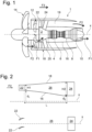
- FIG. 1 shows a schematic sectional view of a turbomachine 1.
- An inner casing 2 guides a primary flow F1 which successively passes through compressors 4 (low and high pressure), a combustion chamber 6 and turbines 8 (high and low pressure), before escaping through a nozzle 10.
- the energy of the combustion drives the turbines 8 in rotation.
- the turbines 8 drive the compressors 4, directly by means of transmission shafts, or indirectly by means of reducers.
- the shafts are held by bearings which must be lubricated.
- the turbines 8 also rotate a fan 12 which sets in motion a secondary flow F2.
- the turbomachine 1 comprises a propeller 14 which propels a tertiary flow F3. Most of the thrust of the turbomachine is generated by the propulsion of the flow F3 by the propeller 14, which is called “propulsive".
- the flow F2 is called “non-propulsive” and is allocated to ancillary functions (cooling).
- the primary flow F1 is used as an oxidant to ensure the rotation of the turbines and therefore of the fan 12 and the propeller 14.
- a fairing 16 and a nacelle 18 delimit a passage 19 which is traversed by the secondary flow F2.
- Structural arms 20 take up the forces between the nacelle 18 and the engine casing 2.
- An annular row of stator vanes 22 (“outlet guide vanes”, OGV) can be arranged downstream of the fan 12 to straighten the flow F2.
- the fan 12 and the propeller 14 can rotate in opposite directions to each other by means of a gear reducer (not shown).
- This reducer can also greatly reduce the rotational speed (between the turbines and the fan/propeller).
- the gearbox is lubricated.
- the oil circuit must dissipate stored heat to maintain its lubricating properties and keep the turbomachine components within an optimal operating temperature range. Significant thermal energy must therefore be dissipated by the oil.
- an air-oil exchanger 24 can be arranged in the secondary flow F2.
- the oil can be cooled by heat exchange with the abundantly available cold air.
- FIG. 2 shows, at the top, a schematic axial sectional view of a detail of the turbomachine of the Figure 1 . These are the blades 22 and the heat exchanger 24.
- the exchanger 24 may be formed from a matrix defining finned corridors traversed by air and in thermal conduction with pipes traversed by oil.
- An example is given in the document EP 3 696 389 A1 .
- a known solution is to provide a diffusion channel 26. This may be part of the passage 19 and be delimited radially by the fairing 16 and the nacelle 18, or by additional fairing elements optimizing the desired geometry for the passage of the secondary flow F2 (not shown).
- the axial length of the diffusion channel denoted L
- This sufficient length is a function of H1, the radial height of the air stream receiving the flow F2 at the outlet of the blades, as well as the ratio of the areas “seen by the flow” between the exchanger 24 and the blades 22 (therefore a function of the internal diameters d1, d2 and external diameters (d1+2*H1), (d2+2*H2) delimiting the fairing 16 and the nacelle 18).
- a speed reduction of a factor of 2 to 5 can be expected, for example, from a Mach number of 0.4-0.5 to 0.1-0.2.
- the part at the bottom of the Figure 2 shows a radial view of the blades 22, the diffusion channel 26 and the exchanger 24.
- FIG. 3 represents a partial view of the secondary flow F2 in a turbomachine according to the invention.
- a diffusion channel 26 is provided to slow down the flow F2.
- the channel 26 is subdivided by means of fins 28 into several passages 30.
- the fins 28 may be carried by vanes 22 which extend axially in the diffusion channel 26.
- the length l of the diffusion channel 26 is inversely proportional to the number of passages. Thus, l may be in this example four times smaller than L (annotated on the Figure 2 ).
- the lower part of the Figure 3 shows a radial view. It can be seen in particular that the fins 28 can extend over more than half the downstream part of the blades 22, or even more than two-thirds.
- the blades 22 which conduct the flow towards the exchanger 24 are provided with fins 28.
- the other blades i.e. which are traversed by a flow which will not pass through the exchanger
- the blades which do not conduct the flow towards an exchanger are as short as those of the state of the art (see Figure 2 ).
- Angularly in the annular row of blades 22, a variation in the length of the progressive blades can be provided, from the longest blades preceding an exchanger, to the shortest blades, angularly furthest from the exchanger.
- FIG. 4 shows an isometric view of a blade 22 according to the invention.
- This blade 22 comprises a leading edge 22.1, a trailing edge 22.2, a lower surface 22.3 and an upper surface 22.4.
- the blade 22 comprises an upstream portion 22.5 of length l1 without a fin 28 and a downstream portion 22.6 of length l2 provided with one or more fins 28.
- the upstream portion 22.5 may correspond to a blade geometry in itself with a trailing edge which extends axially, the entire downstream portion 22.6 being formed of a blade extending such a trailing edge.
- the fin(s) 28 may be supported by the extrados or the intrados, or both.
- the length l1 of the upstream portion 22.5 represents between 10 and 50% of the total length of the blade l3.
- l1 is at least 25% of the length l3 of the blade and l2 is at least 2/3 of the length l3 of the blade.
- Blade 22 has a maximum thickness e measured perpendicular to the chord.
- a fin 28 When a fin 28 is cantilevered, i.e. supported by a single blade, it comprises a free end 28.1 which determines the circumferential width E of the fin.
- E is much greater than e, for example at least 5 times greater.
- Each fin 28 comprises an upstream edge 28.2 and a downstream edge 28.3.
- the upstream edge 28.2 may be aerodynamically profiled as a leading edge.
- the downstream edge 28.3 may be aerodynamically profiled as a trailing edge.
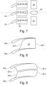
- FIG. 5 brings together a number of possible embodiments for the fins 28 between two circumferentially adjacent blades 22a and 22b. It is understood that all the fins 28 of the same annular row of blades 22 may be of the same nature or be of different natures, and likewise all the fins 28 of the same inter-blade space may be identical or different. Figure 5 brings together different examples.
- Fins 28a and 28b are tapered to facilitate flow at their free ends. Fins 28c and 28d have free ends with complementary profiles to minimize the gap between their ends.
- the fin 28e is carried by the two adjacent blades 22a, 22b. This illustrates that connection fillets can be provided in the vicinity of the blades to minimize disturbances to the air flow. This may be the case for the other examples of fins 28 shown in the Figure 5 .
- Blades 28f and 28g show that vanes can extend across the entire inter-blade space.
- the set of blades 22a, 22b and the vanes 28 which extend from these blades, as well as possibly an angular section of 16 and 18, can be in one piece.
- several adjacent blades and their vanes can be in one piece, thus describing an angular sector of a few degrees of angles to a few tens of degrees (for example 12 sectors of 30° forming the annular row of blades 22).
- the fins 28 may have a concentric curvature with the axis of the turbomachine.
- the curvature in the plane of the Figure 5 can evolve along the axis to approach the shape of the corridors of the exchanger 24.
- the corridors 30 of the diffusion channel can thus serve as a transition to properly prepare the flow for its passage in the exchanger 24.
- FIG. 5 represents six corridors 30 of substantially equivalent radial height, resulting from an equitable distribution of the fins between the root and the head of the blades 22.
- the fins 28 can be further apart at the root of the blade and closer together at the blade head to achieve 30 corridors of approximately equivalent section and thus distribute the F2 flow into a number of corridors of equivalent volume.
- the structural arms 20 may have the same axial position as (or be at least partially arranged to overlap) the heat exchanger 24.
- the blade 22b which is circumferentially aligned with the arm 20 can have a suitable profile. Indeed, the intrados 22.3 and the extrados 22.4 do not meet at a point (seen in the sectional profile perpendicular to the radius).
- the blade 22b is flared.
- a trailing surface 22.7 replaces the usual trailing edge.
- FIG. 7 shows an additional variant.
- the blades 22 are here pierced with conduits 32 allowing the circulation of a fluid, in particular oil.
- the fins 28, whose primary purpose is to slow down the flow F2 for the exchanger 24, can also serve as a heat exchanger by cooling the fluid circulating in the conduits 32.
- the conduits 32 are preferably circumscribed to the axial portion of the blades 22 corresponding to the fins 28 (downstream portion noted 22.6 on the Figure 4 ).
- THE figures 8 and 9 show a radial view of an inter-blade space.
- the blades 28 are described there with upstream 28.2 and/or downstream 28.3 edges which have a profile adapted to minimize disturbances of the flow F2.
- the fin 28 extends from the extrados of the blade 22b only.
- the upstream edge 28.2 has a curvature with an inflection point, roughly following the extrados of the blade 22b on the one hand and roughly following the intrados of the blade 22a on the other hand.
- two fins 28 occupy the inter-blade space.
- the profile of the upstream edge 28.2 of the fins 28 is concave and the profile of the downstream edge 28.3 of the fins 28 is convex.
- each detail of each figure may be provided in combination with each detail of each other figure.
- each of the types of fins shown in the Figure 5 can be used alone or in combination with one or more other types of fins, and each of these types of fins can be provided upstream of a structural arm (as on the Figure 6 ) or attached to a blade fitted with ducts 32 (as on the Figure 7 ).
Landscapes
- Engineering & Computer Science (AREA)
- Mechanical Engineering (AREA)
- General Engineering & Computer Science (AREA)
- Chemical & Material Sciences (AREA)
- Combustion & Propulsion (AREA)
- Architecture (AREA)
- Physics & Mathematics (AREA)
- Fluid Mechanics (AREA)
- Structures Of Non-Positive Displacement Pumps (AREA)
Claims (11)
- Eine Turbomaschine für Luftfahrzeuge (1), die Folgendes umfasst:- einen Verdichter (4), der einen Primärstrom (F1) verdichtet;- ein Gebläse (12), das einen Sekundärstrom (F2) antreibt;- einen ringförmigen Durchgang (19) für den Sekundärstrom (F2) stromabwärts des Gebläses (12);- einen Propeller (14) ohne Verkleidung, der einen tertiären Strom (F3) antreibt, wobei der primäre (F1), der sekundäre (F2) und der tertiäre (F3) Strom voneinander verschieden sind;- eine ringförmige Anordnung von Gleichrichterflügeln (22), die in einem Durchgang (19) angeordnet sind, wobei jeder Flügel (22) einen Einlass (22.3) und einen Auslass (22.4) aufweist; und- mindestens einen Wärmetauscher (24), der in dem Durchgang (19) stromabwärts der Reihe von Flügeln (22) angeordnet ist;wobei die Turbomaschine (1) dadurch gekennzeichnet ist, dass sie ferner Folgendes umfasst:- eine Vielzahl von Diffusionsbahnen (30) stromaufwärts in Bezug auf den mindestens einen Wärmetauscher (24), wobei jede Bahn (30) in Umfangsrichtung durch eine Intrados (22.3) und eine Extrados (22.4) von zwei in Umfangsrichtung benachbarten Flügeln (22a, 22b) begrenzt ist und jede Bahn (30) radial durch mindestens eine Rippe (28) begrenzt ist, die von mindestens einem der beiden in Umfangsrichtung benachbarten Flügel (22a, 22b) getragen wird.
- Die Turbomaschine (1) gemäß Anspruch 1, dadurch gekennzeichnet, dass die mindestens eine Rippe (28g) von der Extrados (22.4) einer (22) der beiden benachbarten Flügeln (22a, 22b) getragen und weist ein Umfangsende (28.1) auf, das von der Innenseite (22.3) des anderen der beiden Flügel (22) auskragt.
- Die Turbomaschine (1) nach Anspruch 1, dadurch gekennzeichnet, dass die mindestens eine Rippe (28f) von der Innenseite (22.3) eines Flügels (22) der beiden in Umfangsrichtung benachbarten Flügel (22a, 22b) getragen wird und ein von der Außenseite (22.4) des anderen der beiden Flügel (22) auskragendes Umfangsende (28.1) aufweist.
- Die Turbomaschine (1) nach Anspruch 1, dadurch gekennzeichnet, dass die mindestens eine Rippe (28e) von der Innenseite (22.3) der einen (22) der beiden in Umfangsrichtung benachbarten Flügel (22) und von der Außenseite (22.4) der anderen der beiden Flügel (22a, 22b) getragen wird.
- Die Turbomaschine (1) nach einem der Ansprüche 2 bis 4, dadurch gekennzeichnet, dass die Grenzfläche zwischen der Rippe (28) und der Oberseite (22.4) oder zwischen der Rippe (28) und der Unterseite (22.3) der es tragenden Flügel (22) aerodynamisch optimiert ist, zum Beispiel durch ein Gewinde.
- Turbomaschine (1) nach Anspruch 1, dadurch gekennzeichnet, dass jede Bahn (30) radial nach innen und/oder radial nach außen durch zwei Rippen (28a, 28b, 28c, 28d) begrenzt ist, von denen eine von der Außenseite (22. 4) eines Flügels (22b) und die andere von der Innenseite (22.3) eines in Umfangsrichtung benachbarten Flügels (22a) getragen wird, wobei sich jede der beiden Rippen (28) in Umfangsrichtung über etwa die Hälfte des Umfangsabstands zwischen den beiden benachbarten Flügeln (22a, 22b) erstreckt.
- Die Turbomaschine (1) nach Anspruch 6, dadurch gekennzeichnet, dass jede der beiden Rippen (28) ein freies Umfangsende (28.1) aufweist, wobei das freie Umfangsende (28.1) des einen Flügels (28a, 28c) neben dem freien Umfangsende (28.1) der anderen Rippe (28b, 28d) angeordnet ist, wobei die freien Umfangsenden (28.1) vorzugsweise aerodynamisch optimiert verjüngt sind.
- Turbomaschine (1) nach einem der vorhergehenden Ansprüche, dadurch gekennzeichnet, dass die beiden in Umfangsrichtung benachbarten Flügel (22a, 22b) und die jeweilige mindestens eine die Schneise (30) zwischen diesen beiden Flügeln (22) begrenzende Rippe (28) aus einem Stück gefertigt sind.
- Turbomaschine (1) nach einem der vorhergehenden Ansprüche, dadurch gekennzeichnet, dass Strukturarme (20) in einer axialen Position angeordnet sind, die diejenige von mindestens einem Wärmetauscher (24) zumindest teilweise überlappt, wobei ein Flügel (22b) der ringförmigen Anordnung von Flügeln (22) in Umfangsrichtung mit jedem Strukturarm (20) ausgerichtet ist, wobei der eine Flügel (22b) vorzugsweise ein aufgeweitetes Austrittsprofil aufweist.
- Turbomaschine (1) nach einem der vorhergehenden Ansprüche, dadurch gekennzeichnet, dass die Flügel (22) winkelmäßig unregelmäßig verteilt sind, wobei die Flügel (22) in dem oder den von dem oder den Wärmetauschern (24) eingenommenen Winkelabschnitt(en) in Umfangsrichtung stärker voneinander beabstandet sind.
- Turbomaschine (1) nach einem der vorhergehenden Ansprüche, dadurch gekennzeichnet, dass die ringförmige Flügelreihe (22) aus Flügeln (22) mit einer oder mehreren Rippen (28) und aus Flügeln (22) ohne Rippen (28) besteht, wobei letztere sich axial über eine Länge (l1) erstrecken, die geringer, vorzugsweise mindestens doppelt oder mindestens dreifach geringer ist als die erste.
Applications Claiming Priority (1)
| Application Number | Priority Date | Filing Date | Title |
|---|---|---|---|
| PCT/EP2021/070433 WO2023001371A1 (fr) | 2021-07-21 | 2021-07-21 | Turbomachine pour aeronef avec echangeur de chaleur |
Publications (2)
| Publication Number | Publication Date |
|---|---|
| EP4374046A1 EP4374046A1 (de) | 2024-05-29 |
| EP4374046B1 true EP4374046B1 (de) | 2025-04-30 |
Family
ID=77338639
Family Applications (1)
| Application Number | Title | Priority Date | Filing Date |
|---|---|---|---|
| EP21754931.0A Active EP4374046B1 (de) | 2021-07-21 | 2021-07-21 | Turbinentriebwerk für ein flugzeug mit wärmetauscher |
Country Status (4)
| Country | Link |
|---|---|
| US (1) | US20250334051A1 (de) |
| EP (1) | EP4374046B1 (de) |
| CN (1) | CN118019898A (de) |
| WO (1) | WO2023001371A1 (de) |
Family Cites Families (16)
| Publication number | Priority date | Publication date | Assignee | Title |
|---|---|---|---|---|
| US4914904A (en) * | 1988-11-09 | 1990-04-10 | Avco Corporation | Oil cooler for fan jet engines |
| CA2046797A1 (en) * | 1990-08-01 | 1992-02-02 | Franklin D. Parsons | Heat exchange arrangement in a gas turbine engine fan duct for cooling hot bleed air |
| FR2734319B1 (fr) * | 1995-05-15 | 1997-07-18 | Aerospatiale | Dispositif pour prelever et refroidir de l'air chaud au niveau d'un moteur d'aeronef |
| GB2373548B (en) * | 2001-03-21 | 2004-06-09 | Rolls Royce Plc | Gas turbine engine aerofoils |
| FR2867506A1 (fr) * | 2004-03-11 | 2005-09-16 | Snecma Moteurs | Aube de redresseur nervuree |
| FR2926322B1 (fr) * | 2008-01-10 | 2012-08-03 | Snecma | Aube bi-pale avec lames. |
| US9359900B2 (en) * | 2012-10-05 | 2016-06-07 | General Electric Company | Exhaust diffuser |
| US10060441B2 (en) * | 2015-05-26 | 2018-08-28 | Pratt & Whitney Canada Corp. | Gas turbine stator with winglets |
| EP3109433B1 (de) * | 2015-06-19 | 2018-08-15 | Rolls-Royce Corporation | Motor, angetrieben durch sc02 mit unabhängigen wellen für verbrennungszykluselemente und antriebselemente |
| GB2545711B (en) * | 2015-12-23 | 2018-06-06 | Rolls Royce Plc | Gas turbine engine vane splitter |
| US10710734B2 (en) * | 2017-08-29 | 2020-07-14 | The Boeing Company | Hybrid aircraft propulsors having electrically-driven augmentor fans |
| US11078795B2 (en) * | 2017-11-16 | 2021-08-03 | General Electric Company | OGV electroformed heat exchangers |
| FR3073891B1 (fr) * | 2017-11-22 | 2019-11-22 | Safran Aircraft Engines | Mat d'un ensemble propulsif |
| FR3074476B1 (fr) * | 2017-12-06 | 2020-12-25 | Safran Aircraft Engines | Turbopropulseur d'aeronef comportant une helice non carenee |
| FR3089552B1 (fr) | 2018-12-10 | 2021-09-17 | Safran Aircraft Engines | Aube comprenant une pale a perforations equipees d’elements rapportes pour delimiter un circuit interne |
| BE1027057B1 (fr) | 2019-02-18 | 2020-09-14 | Safran Aero Boosters Sa | Échangeur de chaleur air-huile |
-
2021
- 2021-07-21 EP EP21754931.0A patent/EP4374046B1/de active Active
- 2021-07-21 CN CN202180101392.9A patent/CN118019898A/zh active Pending
- 2021-07-21 US US18/580,346 patent/US20250334051A1/en active Pending
- 2021-07-21 WO PCT/EP2021/070433 patent/WO2023001371A1/fr not_active Ceased
Also Published As
| Publication number | Publication date |
|---|---|
| EP4374046A1 (de) | 2024-05-29 |
| US20250334051A1 (en) | 2025-10-30 |
| CN118019898A (zh) | 2024-05-10 |
| WO2023001371A1 (fr) | 2023-01-26 |
Similar Documents
| Publication | Publication Date | Title |
|---|---|---|
| EP3696389B1 (de) | Luft-öl-wärmetauscher | |
| BE1026919B1 (fr) | Échangeur de chaleur air-huile | |
| EP3973236B1 (de) | Optimiertes wärmeaustauschsystem für eine turbomaschine | |
| EP3973237B1 (de) | Optimiertes wärmeaustauschsystem einer turbomaschine | |
| EP3671091B1 (de) | Öl-kraftstoff-wärmetauscher | |
| EP3548706B1 (de) | Austrittsleitschaufel einer turbomaschine eines flugzeugs mit einem gebogenen schmierkanal mit verbessertem design | |
| WO2013150248A1 (fr) | Aubage de redressement de sortie | |
| EP3906359B1 (de) | Schaufelblatt für ein turbinentriebwerk | |
| EP4374047B1 (de) | Turbinentriebwerk für ein flugzeug mit wärmetauscher | |
| BE1030462B1 (fr) | Échangeur de chaleur air-huile | |
| FR2989108A1 (fr) | Partie de stator comportant une aube de stator et une structure de conduction thermique | |
| EP4374046B1 (de) | Turbinentriebwerk für ein flugzeug mit wärmetauscher | |
| FR3109962A1 (fr) | Aube directrice de sortie pour turbomachine d’aeronef, comprenant un passage de refroidissement de lubrifiant equipe de parois ondulees | |
| EP4305289B1 (de) | Oberflächenwärmetauscher mit zusätzlichen auslässen | |
| EP4483039B1 (de) | Turbinentriebwerk für ein flugzeug | |
| FR2989109A1 (fr) | Partie de stator comportant une aube de stator et un ensemble de lamelles | |
| WO2023111466A1 (fr) | Echangeur de chaleur a double etage et turbomachine equipee d'un tel echangeur de chaleur |
Legal Events
| Date | Code | Title | Description |
|---|---|---|---|
| STAA | Information on the status of an ep patent application or granted ep patent |
Free format text: STATUS: UNKNOWN |
|
| STAA | Information on the status of an ep patent application or granted ep patent |
Free format text: STATUS: THE INTERNATIONAL PUBLICATION HAS BEEN MADE |
|
| PUAI | Public reference made under article 153(3) epc to a published international application that has entered the european phase |
Free format text: ORIGINAL CODE: 0009012 |
|
| STAA | Information on the status of an ep patent application or granted ep patent |
Free format text: STATUS: REQUEST FOR EXAMINATION WAS MADE |
|
| 17P | Request for examination filed |
Effective date: 20240129 |
|
| AK | Designated contracting states |
Kind code of ref document: A1 Designated state(s): AL AT BE BG CH CY CZ DE DK EE ES FI FR GB GR HR HU IE IS IT LI LT LU LV MC MK MT NL NO PL PT RO RS SE SI SK SM TR |
|
| DAV | Request for validation of the european patent (deleted) | ||
| DAX | Request for extension of the european patent (deleted) | ||
| GRAP | Despatch of communication of intention to grant a patent |
Free format text: ORIGINAL CODE: EPIDOSNIGR1 |
|
| STAA | Information on the status of an ep patent application or granted ep patent |
Free format text: STATUS: GRANT OF PATENT IS INTENDED |
|
| INTG | Intention to grant announced |
Effective date: 20241126 |
|
| GRAS | Grant fee paid |
Free format text: ORIGINAL CODE: EPIDOSNIGR3 |
|
| GRAA | (expected) grant |
Free format text: ORIGINAL CODE: 0009210 |
|
| STAA | Information on the status of an ep patent application or granted ep patent |
Free format text: STATUS: THE PATENT HAS BEEN GRANTED |
|
| AK | Designated contracting states |
Kind code of ref document: B1 Designated state(s): AL AT BE BG CH CY CZ DE DK EE ES FI FR GB GR HR HU IE IS IT LI LT LU LV MC MK MT NL NO PL PT RO RS SE SI SK SM TR |
|
| REG | Reference to a national code |
Ref country code: CH Ref legal event code: EP Ref country code: GB Ref legal event code: FG4D Free format text: NOT ENGLISH |
|
| REG | Reference to a national code |
Ref country code: IE Ref legal event code: FG4D Free format text: LANGUAGE OF EP DOCUMENT: FRENCH |
|
| REG | Reference to a national code |
Ref country code: DE Ref legal event code: R096 Ref document number: 602021030047 Country of ref document: DE |
|
| REG | Reference to a national code |
Ref country code: NL Ref legal event code: MP Effective date: 20250430 |
|
| REG | Reference to a national code |
Ref country code: AT Ref legal event code: MK05 Ref document number: 1790191 Country of ref document: AT Kind code of ref document: T Effective date: 20250430 |
|
| PG25 | Lapsed in a contracting state [announced via postgrant information from national office to epo] |
Ref country code: PT Free format text: LAPSE BECAUSE OF FAILURE TO SUBMIT A TRANSLATION OF THE DESCRIPTION OR TO PAY THE FEE WITHIN THE PRESCRIBED TIME-LIMIT Effective date: 20250901 Ref country code: FI Free format text: LAPSE BECAUSE OF FAILURE TO SUBMIT A TRANSLATION OF THE DESCRIPTION OR TO PAY THE FEE WITHIN THE PRESCRIBED TIME-LIMIT Effective date: 20250430 Ref country code: ES Free format text: LAPSE BECAUSE OF FAILURE TO SUBMIT A TRANSLATION OF THE DESCRIPTION OR TO PAY THE FEE WITHIN THE PRESCRIBED TIME-LIMIT Effective date: 20250430 |
|
| PGFP | Annual fee paid to national office [announced via postgrant information from national office to epo] |
Ref country code: DE Payment date: 20250722 Year of fee payment: 5 |
|
| REG | Reference to a national code |
Ref country code: LT Ref legal event code: MG9D |
|
| PG25 | Lapsed in a contracting state [announced via postgrant information from national office to epo] |
Ref country code: NO Free format text: LAPSE BECAUSE OF FAILURE TO SUBMIT A TRANSLATION OF THE DESCRIPTION OR TO PAY THE FEE WITHIN THE PRESCRIBED TIME-LIMIT Effective date: 20250730 Ref country code: GR Free format text: LAPSE BECAUSE OF FAILURE TO SUBMIT A TRANSLATION OF THE DESCRIPTION OR TO PAY THE FEE WITHIN THE PRESCRIBED TIME-LIMIT Effective date: 20250731 |
|
| PG25 | Lapsed in a contracting state [announced via postgrant information from national office to epo] |
Ref country code: NL Free format text: LAPSE BECAUSE OF FAILURE TO SUBMIT A TRANSLATION OF THE DESCRIPTION OR TO PAY THE FEE WITHIN THE PRESCRIBED TIME-LIMIT Effective date: 20250430 Ref country code: PL Free format text: LAPSE BECAUSE OF FAILURE TO SUBMIT A TRANSLATION OF THE DESCRIPTION OR TO PAY THE FEE WITHIN THE PRESCRIBED TIME-LIMIT Effective date: 20250430 |
|
| PG25 | Lapsed in a contracting state [announced via postgrant information from national office to epo] |
Ref country code: BG Free format text: LAPSE BECAUSE OF FAILURE TO SUBMIT A TRANSLATION OF THE DESCRIPTION OR TO PAY THE FEE WITHIN THE PRESCRIBED TIME-LIMIT Effective date: 20250430 |
|
| PGFP | Annual fee paid to national office [announced via postgrant information from national office to epo] |
Ref country code: BE Payment date: 20250722 Year of fee payment: 5 Ref country code: GB Payment date: 20250724 Year of fee payment: 5 |
|
| PG25 | Lapsed in a contracting state [announced via postgrant information from national office to epo] |
Ref country code: HR Free format text: LAPSE BECAUSE OF FAILURE TO SUBMIT A TRANSLATION OF THE DESCRIPTION OR TO PAY THE FEE WITHIN THE PRESCRIBED TIME-LIMIT Effective date: 20250430 |
|
| PG25 | Lapsed in a contracting state [announced via postgrant information from national office to epo] |
Ref country code: AT Free format text: LAPSE BECAUSE OF FAILURE TO SUBMIT A TRANSLATION OF THE DESCRIPTION OR TO PAY THE FEE WITHIN THE PRESCRIBED TIME-LIMIT Effective date: 20250430 |
|
| PGFP | Annual fee paid to national office [announced via postgrant information from national office to epo] |
Ref country code: FR Payment date: 20250722 Year of fee payment: 5 |
|
| PG25 | Lapsed in a contracting state [announced via postgrant information from national office to epo] |
Ref country code: RS Free format text: LAPSE BECAUSE OF FAILURE TO SUBMIT A TRANSLATION OF THE DESCRIPTION OR TO PAY THE FEE WITHIN THE PRESCRIBED TIME-LIMIT Effective date: 20250731 |
|
| PG25 | Lapsed in a contracting state [announced via postgrant information from national office to epo] |
Ref country code: IS Free format text: LAPSE BECAUSE OF FAILURE TO SUBMIT A TRANSLATION OF THE DESCRIPTION OR TO PAY THE FEE WITHIN THE PRESCRIBED TIME-LIMIT Effective date: 20250830 |
|
| PG25 | Lapsed in a contracting state [announced via postgrant information from national office to epo] |
Ref country code: LV Free format text: LAPSE BECAUSE OF FAILURE TO SUBMIT A TRANSLATION OF THE DESCRIPTION OR TO PAY THE FEE WITHIN THE PRESCRIBED TIME-LIMIT Effective date: 20250430 |
|
| PG25 | Lapsed in a contracting state [announced via postgrant information from national office to epo] |
Ref country code: DK Free format text: LAPSE BECAUSE OF FAILURE TO SUBMIT A TRANSLATION OF THE DESCRIPTION OR TO PAY THE FEE WITHIN THE PRESCRIBED TIME-LIMIT Effective date: 20250430 Ref country code: SM Free format text: LAPSE BECAUSE OF FAILURE TO SUBMIT A TRANSLATION OF THE DESCRIPTION OR TO PAY THE FEE WITHIN THE PRESCRIBED TIME-LIMIT Effective date: 20250430 |
|
| PG25 | Lapsed in a contracting state [announced via postgrant information from national office to epo] |
Ref country code: CZ Free format text: LAPSE BECAUSE OF FAILURE TO SUBMIT A TRANSLATION OF THE DESCRIPTION OR TO PAY THE FEE WITHIN THE PRESCRIBED TIME-LIMIT Effective date: 20250430 |
|
| PG25 | Lapsed in a contracting state [announced via postgrant information from national office to epo] |
Ref country code: EE Free format text: LAPSE BECAUSE OF FAILURE TO SUBMIT A TRANSLATION OF THE DESCRIPTION OR TO PAY THE FEE WITHIN THE PRESCRIBED TIME-LIMIT Effective date: 20250430 |
|
| PG25 | Lapsed in a contracting state [announced via postgrant information from national office to epo] |
Ref country code: SK Free format text: LAPSE BECAUSE OF FAILURE TO SUBMIT A TRANSLATION OF THE DESCRIPTION OR TO PAY THE FEE WITHIN THE PRESCRIBED TIME-LIMIT Effective date: 20250430 |
|
| PG25 | Lapsed in a contracting state [announced via postgrant information from national office to epo] |
Ref country code: IT Free format text: LAPSE BECAUSE OF FAILURE TO SUBMIT A TRANSLATION OF THE DESCRIPTION OR TO PAY THE FEE WITHIN THE PRESCRIBED TIME-LIMIT Effective date: 20250430 |
|
| REG | Reference to a national code |
Ref country code: DE Ref legal event code: R097 Ref document number: 602021030047 Country of ref document: DE |
|
| REG | Reference to a national code |
Ref country code: CH Ref legal event code: H13 Free format text: ST27 STATUS EVENT CODE: U-0-0-H10-H13 (AS PROVIDED BY THE NATIONAL OFFICE) Effective date: 20260224 |
|
| PG25 | Lapsed in a contracting state [announced via postgrant information from national office to epo] |
Ref country code: RO Free format text: LAPSE BECAUSE OF FAILURE TO SUBMIT A TRANSLATION OF THE DESCRIPTION OR TO PAY THE FEE WITHIN THE PRESCRIBED TIME-LIMIT Effective date: 20250430 |
|
| PLBE | No opposition filed within time limit |
Free format text: ORIGINAL CODE: 0009261 |
|
| STAA | Information on the status of an ep patent application or granted ep patent |
Free format text: STATUS: NO OPPOSITION FILED WITHIN TIME LIMIT |
|
| REG | Reference to a national code |
Ref country code: CH Ref legal event code: L10 Free format text: ST27 STATUS EVENT CODE: U-0-0-L10-L00 (AS PROVIDED BY THE NATIONAL OFFICE) Effective date: 20260311 |
|
| PG25 | Lapsed in a contracting state [announced via postgrant information from national office to epo] |
Ref country code: LU Free format text: LAPSE BECAUSE OF NON-PAYMENT OF DUE FEES Effective date: 20250721 |