EP3671014A1 - Led headlight module and led light module for use in such an led headlight module - Google Patents
Led headlight module and led light module for use in such an led headlight module Download PDFInfo
- Publication number
- EP3671014A1 EP3671014A1 EP19202186.3A EP19202186A EP3671014A1 EP 3671014 A1 EP3671014 A1 EP 3671014A1 EP 19202186 A EP19202186 A EP 19202186A EP 3671014 A1 EP3671014 A1 EP 3671014A1
- Authority
- EP
- European Patent Office
- Prior art keywords
- led light
- light module
- optical unit
- module
- led
- Prior art date
- Legal status (The legal status is an assumption and is not a legal conclusion. Google has not performed a legal analysis and makes no representation as to the accuracy of the status listed.)
- Granted
Links
- 230000003287 optical effect Effects 0.000 claims abstract description 150
- 229910052751 metal Inorganic materials 0.000 claims description 10
- 239000002184 metal Substances 0.000 claims description 10
- 239000000463 material Substances 0.000 claims description 7
- 229910000639 Spring steel Inorganic materials 0.000 claims description 6
- 238000000034 method Methods 0.000 claims description 5
- 229910052782 aluminium Inorganic materials 0.000 claims description 2
- XAGFODPZIPBFFR-UHFFFAOYSA-N aluminium Chemical compound [Al] XAGFODPZIPBFFR-UHFFFAOYSA-N 0.000 claims description 2
- 238000009826 distribution Methods 0.000 description 7
- 238000009434 installation Methods 0.000 description 4
- 238000001746 injection moulding Methods 0.000 description 3
- 230000003993 interaction Effects 0.000 description 3
- 238000005452 bending Methods 0.000 description 2
- 238000010276 construction Methods 0.000 description 2
- 230000002950 deficient Effects 0.000 description 2
- 238000013461 design Methods 0.000 description 2
- 238000011161 development Methods 0.000 description 2
- 238000004519 manufacturing process Methods 0.000 description 2
- 239000004065 semiconductor Substances 0.000 description 2
- 239000000243 solution Substances 0.000 description 2
- 230000003044 adaptive effect Effects 0.000 description 1
- 239000000853 adhesive Substances 0.000 description 1
- 230000001070 adhesive effect Effects 0.000 description 1
- AZDRQVAHHNSJOQ-UHFFFAOYSA-N alumane Chemical group [AlH3] AZDRQVAHHNSJOQ-UHFFFAOYSA-N 0.000 description 1
- 230000000295 complement effect Effects 0.000 description 1
- 239000004020 conductor Substances 0.000 description 1
- 239000011521 glass Substances 0.000 description 1
- 239000003292 glue Substances 0.000 description 1
- 230000017525 heat dissipation Effects 0.000 description 1
- 239000004922 lacquer Substances 0.000 description 1
- 239000003550 marker Substances 0.000 description 1
- 239000000203 mixture Substances 0.000 description 1
- BASFCYQUMIYNBI-UHFFFAOYSA-N platinum Chemical compound [Pt] BASFCYQUMIYNBI-UHFFFAOYSA-N 0.000 description 1
- 238000004080 punching Methods 0.000 description 1
- 238000006748 scratching Methods 0.000 description 1
- 230000002393 scratching effect Effects 0.000 description 1
- 238000012546 transfer Methods 0.000 description 1
- 238000013519 translation Methods 0.000 description 1
- 230000000007 visual effect Effects 0.000 description 1
Images


Classifications
-
- F—MECHANICAL ENGINEERING; LIGHTING; HEATING; WEAPONS; BLASTING
- F21—LIGHTING
- F21S—NON-PORTABLE LIGHTING DEVICES; SYSTEMS THEREOF; VEHICLE LIGHTING DEVICES SPECIALLY ADAPTED FOR VEHICLE EXTERIORS
- F21S41/00—Illuminating devices specially adapted for vehicle exteriors, e.g. headlamps
- F21S41/10—Illuminating devices specially adapted for vehicle exteriors, e.g. headlamps characterised by the light source
- F21S41/14—Illuminating devices specially adapted for vehicle exteriors, e.g. headlamps characterised by the light source characterised by the type of light source
- F21S41/141—Light emitting diodes [LED]
- F21S41/147—Light emitting diodes [LED] the main emission direction of the LED being angled to the optical axis of the illuminating device
- F21S41/148—Light emitting diodes [LED] the main emission direction of the LED being angled to the optical axis of the illuminating device the main emission direction of the LED being perpendicular to the optical axis
-
- F—MECHANICAL ENGINEERING; LIGHTING; HEATING; WEAPONS; BLASTING
- F21—LIGHTING
- F21S—NON-PORTABLE LIGHTING DEVICES; SYSTEMS THEREOF; VEHICLE LIGHTING DEVICES SPECIALLY ADAPTED FOR VEHICLE EXTERIORS
- F21S41/00—Illuminating devices specially adapted for vehicle exteriors, e.g. headlamps
- F21S41/10—Illuminating devices specially adapted for vehicle exteriors, e.g. headlamps characterised by the light source
- F21S41/19—Attachment of light sources or lamp holders
- F21S41/192—Details of lamp holders, terminals or connectors
Definitions
- the present invention relates to an LED headlight module according to the preamble of claim 1, preferably for use in a motor vehicle for generating a main light function, and an LED light module for use in such an LED headlight module. Furthermore, the invention relates to a method for mounting an LED light module of an LED headlight module on an optical unit of the LED headlight module separate from the LED light module according to the preamble of claim 18.
- the LED light sources are in generally not exchangeable or only with considerable effort.
- the precise installation of the LED light module on the optics unit is very complex and error-prone when producing LED headlight modules.
- the heat sink is constructed in two parts, a deflection element in the form of a reflector being attached to a first part of the heat sink, for example by means of screws, and an LED light source being attached and making electrical contact with the other part of the heat sink.
- the two parts of the heat sink have mutually complementary positioning and fastening means, so that the two parts can be arranged in a defined position relative to one another during assembly and can be detachably fastened to one another by means of an adapter designed as a metal bracket.
- the positioning and fastening means must be formed directly on or in the two parts of the heat sink.
- the metal bracket merely holds the one heat sink part relative to the other heat sink part in a vertical z-direction after these have been previously positioned in an xy plane by the positioning means.
- the heat sink is designed in two parts in order to achieve interchangeability of the light source. This reduces the efficiency of the heat sink and increases the number of parts. In addition, the requirement for fastening the deflecting element to one part of the heat sink by means of screws results in increased assembly effort.
- Another disadvantage of the known LED headlight module is that the positioning pins and the corresponding positioning recesses have to be formed on or in the two parts of the heat sink. Due to the design, both parts of the heat sink must be designed as die-cast aluminum parts, which results in increased costs.
- an LED headlight module in which an LED light source can be replaced as part of an LED light module. It is a position-accurate assembly of the LED light module with respect to an optical unit with a deflection element without additional or separate mounting devices by simply clipping or The entire LED light module can be locked onto the optical unit. By simply unlocking the clip or snap connection, disassembly or replacement of the LED light module is also possible.
- the LED light module is placed obliquely on a front edge of a base plate of the optical unit directed in the light exit direction, so that the front edge engages in undercuts formed on the light module, which hold the light module on the optical unit in the z direction.
- the light module is then pivoted downward about an axis of rotation, which is formed by the front edge of the base plate held in the undercuts, so that the rear edge of the base plate engages with latching hooks formed on the light module, which also engage the light module in z. Hold the direction on the optical unit.
- a spring element acting on the rear edge of the base plate presses the light module or stop elements attached thereto against a reference geometry formed on the front edge of the base plate, so that the light module is also fixed in a defined position in the xy plane.
- the relatively large space requirement which is required for the pivoting movement of the light module relative to the optical unit during assembly or disassembly, is problematic.
- the reflector can be damaged in the field of vision (e.g. scratching or damage to a reflection surface of the reflector).
- the spring travel of the locking hooks and the spring element must be made relatively short for reasons of space, so that the locking hooks and the spring element can be overstretched when the light module is mounted on the optical unit.
- the present invention is therefore based on the object of proposing an LED headlight module with exchangeable LED light source in which, on the one hand, assembly and disassembly is simple, quick and takes up as little space as possible and on the other hand, the LED light source is held as precisely as possible after installation, safely and reliably with respect to an optical unit of the headlight module.
- an LED headlight module for a motor vehicle headlight is proposed with the features of claim 1.
- an LED headlight module which comprises an LED light module and an optical unit separate from the LED light module.
- the LED light module has a circuit board on which at least one LED light source for emitting light is fastened and electrically contacted, and an adapter separate from the circuit board for releasably fastening the LED light module to the optical unit.
- the optical unit has at least one optical deflecting element for bundling and deflecting at least some of the emitted light in a light exit direction of the LED headlight module.
- the circuit board and the adapter are at least indirectly rigidly attached to one another.
- the LED light module has at least one stop element which is arranged and designed on the LED light module in such a way that it enables the LED light module to be positioned in an exact position relative to the optical unit in an xy plane by using a corresponding reference geometry the optical unit interacts.
- the adapter comprises at least one spring element which, when the LED light module is mounted, presses the at least one stop element of the LED light module to position the LED light module in the xy plane against the reference geometry of the optical unit.
- the adapter also has a fastening arrangement for releasably fastening the precisely positioned LED light module in the z direction on the optical unit.
- the fastening arrangement comprises at least one first holding element which is articulated on the adapter in an articulation area and has a holding arm which is resilient in a z-direction and an active surface formed thereon, which extends essentially in a plane parallel to the xy plane and which has the LED positioned exactly in position.
- Light module holds in the z direction on the optical unit.
- the active surface acts on a partial area of the optical unit which, when the LED light module is positioned precisely, lies opposite the partial area of the optical unit on which the at least one stop element acts.
- the LED light module of the LED headlight module comprises a circuit board and an adapter for fastening the LED light module to the optical unit of the LED headlight module.
- the deflecting element of the optical unit is designed, for example, as a reflector with a specular reflection surface on a side of the reflector directed in the light exit direction.
- the adapter can be made of plastic or a metal sheet, in particular a spring steel sheet.
- the adapter can also consist of a material mix or of several components made of different materials (e.g. plastic and spring steel).
- the LED light module preferably also comprises a heat sink, preferably in the form of a one-piece bent sheet metal part, for example made of a spring steel sheet.
- the adapter and the board are rigidly attached to each other. They are preferably fastened together on a heat sink of the LED light module.
- the adapter can be fastened to a heat sink by means of screws or in some other way, the circuit board being clamped between the adapter and the heat sink. Since the circuit board, the adapter and the heat sink are then rigidly connected to one another, the various elements for the precise positioning and fastening of the LED light module relative to the optical unit could in principle be formed or arranged on any part (circuit board, adapter or heat sink) of the light module .
- the adapter can be produced easily and inexpensively and can be provided with suitable elements without any problems, which enable the LED light module to be positioned and / or attached to the optical unit in a precise position. This results in a particularly simple and inexpensive construction of the LED light module.
- the fastening arrangement also has at least one second holding element articulated on the adapter in an articulation area with a holding arm resilient in a z direction and an active surface formed thereon, which is essentially in a plane parallel to the xy- Plane extends and which holds the precisely positioned LED light module in the z-direction on the optical unit, the active surface acting on a partial area of the optical unit, which in the precisely positioned LED light module between the partial area of the optical unit, on the the at least one first holding element acts, and lies in the partial area of the optical unit on which the at least one stop element acts.
- the articulation area of the holding element lies on the adapter and the at least one stop element of the LED light module.
- the second holding elements differ from the first holding elements in particular in that they act on different partial areas of the optical element in order to hold the LED light module securely detachably in the z direction on the optical element. While the active surface of the at least one first holding element acts more in an edge region on a surface of the base plate of the optical unit, the active surface of the at least one second holding element acts on the surface of the base plate at a distance from the edge region rather than at a distance from the edge region.
- all holding elements which releasably attach the precisely positioned LED light module in the z-direction to the optical unit, are articulated on the adapter on the same side of the adapter in the articulation area.
- the LED light module is preferably placed obliquely from behind on a rear edge of a base plate of the optical unit.
- the light module is pressed with low force so far in the direction of the front edge of the base plate (in the light exit direction of the headlight module) against the force of the at least one spring element until the at least one stop element is pushed over the referencing geometry of the optical unit at the front edge of the base plate and the LED light module can be pivoted about an axis of rotation running along the rear edge of the base plate.
- the resilient holding arm of the holding element or elements slides along with its active surface, starting from the rear edge of the base plate on the underside of the base plate, until it reaches the portion of the base plate via which it acts on the optical unit and due to its spring action, the LED light module and the optical unit press against each other in the z direction.
- the spring force of the at least one spring element pushes the at least one stop element of the LED light module against the referencing geometry of the optical unit, so that the LED light module is also positioned and held in the xy plane relative to the optical unit.
- the LED headlight module With the LED headlight module according to the invention, a particularly simple and positionally accurate mounting of the LED light module with respect to the optical unit or the deflection element is possible without additional or separate mounting devices. In addition, simple disassembly or replacement of the LED light module is possible. It is particularly advantageous that only a very small space for the pivoting movement is required for the assembly or disassembly of the light module. Furthermore, there can be no damage to the reflector in the viewing area (for example in the area of a reflecting reflection surface or visible diaphragms), since the light module is placed on the rear edge of the base plate of the optical unit that is outside the viewing area.
- the holding arm of the holding element or elements is designed to be resilient in the z direction, the spring travel of the holding arm being designed to be relatively long, so that an overextension of the holding arm of the holding element or elements is excluded when the LED light module is mounted on the optical unit.
- the LED headlight module according to the invention has a robust referencing geometry (cf. for example also the DE 10 2016 119 792 A1 ) for precise referencing of the LED light module relative to the optical unit in an xy plane.
- the referencing geometry is formed on the optical unit, preferably on a front edge of a base plate of the optical unit, and interacts with the stop elements which are formed on the LED light module.
- the stop elements are preferably integrated in or attached to the adapter which is attached to the LED light module. If the adapter is made of plastic, the stop elements can be formed at the same time as the adapter is being manufactured, for example by means of injection molding. Alternatively, the stop elements can also be arranged or formed on the circuit board.
- referencing pins can be attached by means of a press fit, by means of screws or in some other way.
- a reference part made of plastic, which has appropriate Referencing surfaces that act as stop elements have to be attached to the circuit board, the adapter or the heat sink. It is advantageous if the referencing part is attached to the heat sink of the light module together with the adapter and the circuit board, for example by means of a common screw.
- the referencing geometry of the optical unit is designed, in cooperation with the stop elements of the LED light module, to position it in an xy plane relative to the optical unit.
- the referencing geometry is preferably formed on a front edge of a base plate of the optical unit.
- the referencing geometry includes, in particular, a first stop surface acting in the x direction, which extends in the y direction, and in the y direction offset from the first stop surface, two further V-shaped stop surfaces, each in x and in act in the y direction.
- the first stop surface of the referencing geometry interacts with a corresponding first stop element of the LED light module.
- the two further V-shaped stop faces interact with a corresponding other stop element of the LED light module.
- the LED light module is pre-assembled by attaching the adapter to the heat sink together with the circuit board. This can be done in particular by means of screws. With the adapter attached to the heat sink, the circuit board can be clamped between the adapter and the heat sink and thus indirectly attached to the adapter and the heat sink. It is also conceivable that the circuit board is attached to the heat sink independently of the adapter, for example by means of at least one screw. Integrated in the adapter are both positioning means for the precise positioning of the adapter relative to the LED light source or the printed circuit board, as well as the stop elements which interact with the reference geometry for precise positioning relative to the optical unit.
- the at least one spring element and the holding arms of the first and - if present - second holding elements are integrally formed with the adapter. If the LED light module is positioned exactly in relation to the optical unit with the deflecting element in the xy plane and is correctly positioned and held in the z direction, the LED light source is in the required position and Alignment relative to the deflection element (for example the reflection surface of a reflector) so that the LED headlight module can generate the intended light distribution.
- the deflection element for example the reflection surface of a reflector
- the preassembled LED light module is then manually placed obliquely on the optical unit, pivoted relative to it and then automatically held in the precisely defined position on the optical unit by means of the holding arm of the holding element or elements.
- the LED light module executes an approximately translatory movement in a positive x-direction and approximately parallel to a surface extension of the base plate of the optical unit until the stop elements of the LED light module are located in front of the referencing geometry of the optical unit, so that the optical unit can then be pivoted about an axis of rotation, which is approximately formed by the rear edge region of the base plate, as part of the pivoting movement.
- the stop elements come into active engagement with the referencing geometry.
- the axis of rotation preferably runs parallel to the y-axis, a front section of the light module moving in the direction of the optical unit as part of the pivoting movement.
- a spring force of the at least one holding arm of the holding element or elements acts in the direction of the pivoting movement.
- the circuit board of the light module preferably runs parallel to the base plate of the optical unit.
- the light module can now be released, two things then happening in particular: the at least one spring element presses the at least one stop element of the LED light module against the referencing geometry of the Optics unit (and thus ensures that the light module is positioned precisely in relation to the optics unit in the xy plane) and the at least one holding arm of the holding element or springs, which resilient in the z direction, presses the light module and the optics unit against each other (and thus ensures exact positioning) in the z direction).
- the LED light module is thus positioned and held in three-dimensional space relative to the optical unit.
- the LED headlight module not only has the advantage that a defective LED light source (together with the LED light module) can be replaced, but also that the LED headlight module is installed by the manufacturer of the headlight module, in particular that the positioner is fixed correctly and in position LED light module on the optics unit, can be carried out quickly and reliably even by unskilled people or even fully automated using an assembly robot.
- the term position encompasses both a position and an orientation of the light module relative to the optical unit.
- a translatory movement of the light module relative to the optical unit in the positive x direction is initially carried out against the spring force of the at least one spring element, so that the stop elements stand out from the referencing geometry.
- a pivoting movement of the light module relative to the optics unit is then carried out about the axis of rotation, a front section of the light module moving away from the optics unit as part of the pivoting movement.
- the spring force of the at least one holding arm of the holding element or elements acts counter to this pivoting movement.
- the LED light module is moved in an approximately translatory movement in a negative x-direction and moved approximately parallel to a surface extension of the base plate of the optical element until the effective surface of the at least one holding arm of the holding element or elements no longer coincides with the Optics unit is in contact.
- the light module can then be removed from the optics unit and replaced.
- no holding or spring elements or other fastening or holding elements are provided which grip around or hold the front edge of a base plate of the optical unit.
- All holding or spring elements are operatively connected to the rear edge of the base plate or, if necessary, a partial area of the base plate between the rear and the front edge.
- the at least one spring element, as well as the at least one holding arm of the holding element or elements in the articulation area are preferably articulated on the adapter on its rearward side in the assembled state of the LED light module in such a way that they are arranged next to one another in particular in the y direction.
- No holding or spring elements are arranged on the forward-facing side of the adapter.
- a motor vehicle headlight is designated in its entirety with reference number 2.
- the headlight 2 is designed for installation in a corresponding installation opening on the front of a motor vehicle.
- the headlight 2 comprises a housing 4, which is preferably made of plastic.
- the housing 4 has a light exit opening 8, which is closed by a transparent cover plate 10.
- This is preferably made of plastic or glass. It can be designed with or without optically active elements (for example prisms or cylindrical lenses) for scattering the light passing through.
- An LED headlight module 12 according to the invention is arranged in the interior of the housing 4 Figure 23 is only shown schematically.
- the LED headlight module 12 serves to generate any headlight function (so-called main light function) or a part thereof.
- the headlight function can be, for example, a low beam, a high beam, a fog light, or any adaptive light distribution (e.g. in the form of bad weather light, a city light, a country road or overland light, a motorway light, a so-called continuous high beam (also as glare-free high beam or partial high beam referred to) or in the form of a so-called marker light).
- At least one further light module can also be arranged in the interior of the housing 4 of the headlight 2, which either generates another headlight function alone or together with the LED headlight module 12 the headlight function.
- the further light modules can also be designed as LED modules, or else have other types of light sources, for example an incandescent lamp, gas discharge lamp, laser light source, etc.
- the at least one further light module can also be designed as an LED light module according to the invention.
- the at least one further light module can be designed as a so-called reflection module or as a projection module.
- the light emitted by the light source is bundled by means of primary optics, for example in the form of a reflector, and deflected in the light exit direction 6.
- the light distribution of the resulting headlight function is essentially determined by the shape of a reflecting surface of the reflector. This usually has a parabolic basic shape.
- a scattering, in particular in the horizontal direction, of the light passing through can be brought about by optically active elements on the cover plate 10 and / or the reflection surface.
- the light emitted by the light source is bundled by means of primary optics, for example in the form of a reflector or a lens element, and deflected in the light exit direction 6.
- primary optics for example in the form of a reflector or a lens element
- deflected in the light exit direction 6 When using a reflector, it usually has an ellipsoidal basic shape.
- a secondary lens is arranged in the beam path of the light bundled by the primary lens, for example in the form of a projection lens or a projection reflector, which maps an intermediate light distribution generated by the primary lens in a focal plane of the secondary lens as a resultant light distribution of the headlight function on the road ahead of the motor vehicle.
- a diaphragm arrangement with an edge can be arranged which shadows or deflects part of the bundled light and the edge of which is projected onto the road by the secondary optics as a light-dark boundary of a dimmed light distribution.
- the LED headlight module 12 can be designed as a reflection module or as a projection module.
- secondary optics for example in the form of a projection lens, are not shown in the figures.
- LED headlight modules 12 use semiconductor light sources, in particular in the form of one or more light-emitting diodes (LEDs) 22, which are combined to form an LED chip 22a. Under normal operating conditions, semiconductor light sources generally have a significantly longer lifespan than conventional light sources. In practice, no LED headlight modules 12 have yet been known in which the LED light sources 22 can be exchanged easily, quickly and inexpensively. Currently, if one or more LED light sources 22 is defective, the entire headlight 2 must always be replaced, which is associated with considerable effort and correspondingly high costs for material and working time. The previously proposed solutions for LED headlight modules with interchangeable LED light sources (e.g.
- the LED headlight module 12 comprises an LED light module 20 with at least one LED light source 22 for emitting light and an optical unit 24 separate from the LED light module 20 with at least one optical deflection element 26.
- the deflection element 26 is designed, for example, as a reflector .
- the deflection element 26 can of course also be used as a lens or as another suitable optical element Element be formed. In this case, the lens would then have a receptacle or holder on which the LED light module 20 could be positioned precisely and releasably attached.
- the LED light module 20 comprises a printed circuit board (PCB) 28, on which the at least one LED light source 22 is fastened and electrically contacted.
- PCB printed circuit board
- a total of three LED light sources 22 are arranged next to one another in the y direction on an LED chip 22a.
- the contacting of the LED light sources 22 leads via conductor tracks of the circuit board 28 to an electrical connector 28a.
- the electrical connector 28a is preferably arranged on the side of the circuit board 28 on which the LED light sources 22 are located.
- a control device for controlling and / or supplying energy to the LED light sources 22 is connected to the LED light module 20 by means of a corresponding plug connector (not shown).
- the LED light module 20 comprises a heat sink 30 made of a material with a good thermal conductivity.
- the heat sink 30 is in particular made of a metal with a thermal conductivity of over 70 W / (m ⁇ K), preferably of over 100 W / (m ⁇ K), very particularly preferably of at least 235 W / (m ⁇ K).
- Aluminum is proposed in particular as the material for the heat sink 30.
- the heat sink 30 is preferably designed as a one-piece bent sheet metal part.
- the LED light module 20 comprises an adapter 32 separate from the heat sink 30 and the circuit board 28 for the precise positioning and releasable attachment of the LED light module 20 to the optical unit 24 of the LED headlight module 12.
- the adapter 32 (cf. Figure 4 ) made of a metal sheet, in particular a spring steel sheet.
- a metal sheet in particular a spring steel sheet.
- the adapter 32 can be punched out of the metal sheet and then bent into the desired shape.
- the adapter 32 is rigidly fastened by means of three fastening screws 34, which are guided through corresponding holes 34a in the adapter 32, on an underside (the surface directed in the negative z direction) of the heat sink 30. It is also conceivable to use a different number of fastening screws 34 use or attach the adapter 32 to the heat sink 30 in a manner other than by means of screws.
- the circuit board 28 When the adapter 32 is fastened to the heat sink 30, the circuit board 28 is arranged in between, so that when the adapter 32 is fastened, it is clamped between an upper side (the surface directed in the positive z direction) of the adapter 32 and the underside of the heat sink 30, and thus indirectly is attached to the adapter 32 and the heat sink 30.
- Suitable positioning means pins and corresponding recesses or holes
- the positioning means of the adapter 32 can be easily formed in one piece with the rest of the adapter 32 during the manufacture of the adapter 32, for example when punching or bending.
- Corresponding positioning means that can engage with the positioning means of the adapter 32 can be formed in a simple manner in the board 28.
- Another type of attachment of the circuit board 28 to the heat sink 30 would also be conceivable, e.g. Glue or weld.
- the LED light sources 22 During the operation of the LED light sources 22, they emit heat, which is conducted indirectly via the circuit board 28 to the heat sink 30, which emits them to the environment.
- special areas can be provided in the board 28, or the entire board 28 can be made of a special material or have a special structure, so that a particularly good heat transfer from the light sources 22 or the LED chip 22a to the heat sink 30 is made possible.
- FIG. 1 to 17 A first exemplary embodiment of an LED light module 20 according to the invention is shown.
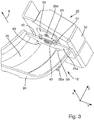
- This has at least one stop element 46, 48, which is arranged on the LED light module 20 and designed to position the LED light module 20 in an exact position relative to the optical unit 24 in at least one plane with a corresponding reference geometry 40, 42, 44 the optics unit 24 (cf. Figures 3 and 16 ) cooperate.
- two stop elements 46, 48 are provided. Through the interaction of the stop elements 46, 48 with the referencing geometry 40, 42, 44, the relative position between the optics unit 24 and the LED light module 20 that can be detachably attached to it can be predetermined precisely in an xy plane.
- the referencing geometry comprises a first stop surface 40, which acts in the x direction and extends in the y direction. Furthermore, the referencing geometry comprises two further V-shaped stop faces 42, 44, which each act in the x and y directions and each extend obliquely to the x direction and the y direction. The two V-shaped stop surfaces 42, 44 are formed offset in the y-direction from the first stop surface 40 on the optical element 24.
- the optics unit 24 has a base plate 24a on which the deflection element 26, which is designed as a reflector, is arranged.
- the base plate 24a and the deflection element 26 are formed as a single piece.
- the first abutment surface 40 and the further inclined abutment surfaces 42, 44 are preferably formed on a front edge section 24d of the base plate 24a directed in the direction of travel or x-direction.
- the stop elements are designed as referencing pins 46, 48 which are attached to the circuit board 28.
- the referencing pins 46, 48 are inserted into holes in the board 28 which are drilled with high precision with respect to the LEDs 22 and are fixed therein.
- the pins 46, 48 can be fixed on the circuit board 28, for example, by means of a press fit, adhesive, lacquer or in some other way.
- the referencing pin 48 when the LED light module 20 is mounted on the optics unit 24, has an operative connection with the abutting surfaces 42, 44 of the optics unit 24 and ensures that the LED light module 20 in the x-direction and in the y-direction is positioned relative to the optical unit 24.
- the referencing pin 46 interacts with the stop surface 40 and ensures that the LED light module 20 can no longer be rotated about a vertical axis of rotation, which is defined by a longitudinal axis of the referencing pin 48 (parallel to the z-axis) is.
- the stop elements 46, 48 are not formed on the board 28, but in the form of referencing surfaces of a referencing part 60 made of plastic (cf. Figure 5 ).
- the referencing part 60 is fastened to the LED light module 20 or with respect to the circuit board 28, the heat sink 30 and the adapter 32, for example by means of one of the screws 34 which is guided through an opening 62 in the referencing part 60.
- Other types of fastening are also conceivable.
- the referencing surfaces 46, 48 are in particular designed as distal end surfaces of conically shaped or tapered projections 64 directed in the negative x direction.
- the reference part 60 can be produced by means of an injection molding process. If the adapter 32 is made of plastic, the referencing part 60 as an integral part of the adapter 32 could be formed in one piece with it and produced together with it.
- the adapter 32 has two spring elements 50 which, when the LED light module 20 is mounted, the stop elements 46, 48 of the LED light module 20 for the positionally accurate positioning of the LED light module 20 relative to the optical unit 24 against the referencing geometry 40, 42, 44 Press the optics unit 24.
- the spring elements 50 are each formed, for example, as a leaf spring or spring clip in one piece with the adapter 32 and are supported on the optical unit 24. They are preferably supported on a rear edge section 24c (directed in the negative x direction) of the base plate 24a of the optical unit 24.
- the base plate 24a is then, as it were, clamped between the stop elements 46, 48 and the spring elements 50. Due to the interaction of the spring elements 50 on the one hand and the stop elements 46, 48 and the referencing geometry 40, 42, 44 on the other hand, the LED light module 20 is positioned in the xy plane relative to the optics unit 24.
- the adapter 32 also has a fastening arrangement for releasably fastening the precisely positioned LED light module 20 to the optics unit 24.
- the fastening arrangement is designed in particular, the LED light module 20 in the to hold the z direction on the optical unit 24.
- the fastening arrangement has a first holding element 56 articulated on the adapter 32 in an articulation area 78 with a holding arm 56a resilient in a z direction and an active surface 56b formed thereon, which extends essentially in a plane parallel to the xy plane and which holds the precisely positioned LED light module 20 in the z-direction on the optics unit 24, the active surface 56b acting on a partial area of the optics unit 24 which, when the precisely positioned LED light module 20 is located, lies opposite the partial area of the optics unit 24 on which the at least one Stop element 46, 48 acts.
- more than one holding element 56 or the holding arm 56a can also be provided.
- the articulation area 78 of the holding arm 56a is spaced apart from the stop elements 46, 48 or the front edge area 24d of the base plate 24a.
- the active surface 56b of the holding arm 56a can also act on a partial area of the optical unit 24 which lies in a rear edge area 24c of the base plate 24a.
- the holding arm 56a is designed to be resilient in the z direction, so that when the LED light module 20 is mounted on the optical unit 24, the base plate 24a of the optical unit 24 can be pushed under the holding arm 56a without problems and the light module 20 can nevertheless be securely mounted in z Direction is held relative to the base plate 24a.
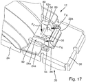
- the fastening arrangement has two second holding elements 52, 54 articulated on the adapter 32 in an articulation area 78, each with a holding arm 52a, 54a resilient in the z direction and an active surface 52b, 54b formed thereon.
- a second holding element or more than the two holding elements 52, 54 or two holding arms 52a, 54a can be provided.
- the articulation area 78 of the holding arms 52a, 54a is spaced apart from the stop elements 46, 48 or the front edge area 24d of the base plate 24a.
- the articulation area 78 of the holding elements 52, 54, 56 is preferably located on a rear area of the adapter directed against the light exit direction 6 32 arranged so that the articulation region 78 is arranged behind the rear edge region 24c of the base plate 24a when the LED light module 20 is positioned precisely on the optical unit 24.
- This has, for example DE 10 2017 122 560 the advantage that there are no holding elements 52, 54 on the front edge region 24d of the base plate 24a in the light emission region of the light reflected by the deflection element 26, which could disrupt the light distribution.
- the active surfaces 52b, 54b extend essentially in a plane parallel to the xy plane and hold the precisely positioned LED light module 20 in the z direction on the optical unit 24.
- the active surfaces 52b, 54b of the holding arms 52a, 52b act on a partial area the optical unit 24, which in this example lies between the articulation area 78 of the holding elements 52, 54 on the adapter 32 and the stop elements 46, 48 of the LED light module 20. More specifically, the active surfaces 52b, 54b of the holding arms 52a, 52b act on a partial area of the base plate 24a which lies between the front edge area and the rear edge area of the base plate 24a.
- two passage openings 80 are formed in the deflection element 26 adjacent to the base plate 24a, through which the resilient holding arms 52a, 54a extend when the LED light module 20 is held on the optical unit 24, so that the partial area of the base plate 24a on which the active surfaces are located 52b, 54b of the resilient holding arms 52a, 54a of the second holding elements 52, 54 act on a side of the deflection element 26 which is opposite the articulation region 78 of the resilient holding arms 52a, 54a.
- This enables a particularly secure mounting of the LED light module 20 on the optics unit 24.
- the fastening arrangement or the holding arms 52, 54, 56 and the spring elements 50 are formed in one piece with the adapter 32.
- the articulation region 78 of the holding arms 52, 54, 56 and the spring elements 50 are preferably arranged next to one another on the same side of the adapter 32. When the LED light module 20 is mounted, this side is located on the rear edge region of the base plate 24a of the optical unit 24.
- the interaction of the holding arms 52, 54, 56 makes the adapter 32 and with it the entire LED light module 20 special held securely and reliably in the z direction on the base plate 24a of the optical unit 24.
- the LED light module 20 is preassembled by attaching the adapter 32 and the circuit board 28 to the heat sink 30.
- the referencing part 60 with the referencing surfaces 46, 48 can be attached to the circuit board 28 beforehand.
- the referencing part 60 can also be attached to the heat sink 30 separately or together with the adapter 32 and the circuit board 28.
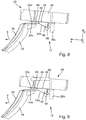
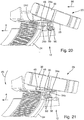
- the pre-assembled LED light module 20 is manually placed on the optics unit 24, in particular on a rear edge section 24c of the base plate 24a (cf. Figures 8 and 19th ) and releasably attached to it by a combined translation / swivel movement (cf. Figures 9 to 11 or 20 to 22).
- the light module 20 according to FIG Figures 18 to 22 only a first central holding element 56 with a holding arm 56a, which is arranged between the two spring elements 50.
- the LED light module 20 is held on the optical unit 24 solely by the holding arm 56a.
- the holding arm 56a also does not act on a partial area of the base plate 24a of the optical unit 24, but rather on a projection 24b which is attached to the deflection element 26 and projects rearward in the negative x direction.
- the preassembled LED light module 20 is first placed on the optical unit 24 from behind in a slightly inclined position with the front section of the light module 20 tilted slightly upwards (cf. Figures 8 and 19th ).
- a translatory movement of the obliquely placed light module 20 in the positive x direction is then carried out (cf. Figures 9 or 20).
- the translatory movement is indicated by an arrow 66.
- the active surfaces 56b; 52b, 54b of the holding arms 56a; 52a, 54a can be arranged on the underside of the partial area of the optical unit 24 on which they act in the assembled position. In the first exemplary embodiment, this is the underside of the base plate 24a of the optical unit 24 (cf.
- the holding element 56 comprises the rear edge region of the projection 24b, ie the active surface 56b of the holding arm 56a lies on the underside of the projection 24b (cf. Figure 10 ).
- the spring elements 50 in the first exemplary embodiment or the one spring element 50 (in the second exemplary embodiment) are elastically deformed against their spring force.
- the translational movement 66 is continued until the stop elements 46, 48 are arranged beyond (or in the positive x direction in front) the referencing geometry 40, 42, 44 of the optical unit 24.
- the LED light module 20 is now pivoted in a pivoting movement about an axis of rotation which is approximately formed by the rear edge region of the base plate 24a (cf. Figures 10 and 21st ). Due to the resilient design of the holding elements 52, 54, 56 in the z direction, the axis of rotation is not precisely defined.
- the pivoting movement is indicated in the figures by an arrow 68 and takes place counterclockwise, ie the front section of the LED light module 20 is moved in the negative z direction.
- the axis of rotation preferably runs parallel to the y-axis.
- the pivoting movement is ended when the underside of the LED light module 20 comes to rest on the upper side of the base plate 24a of the optical unit 24. Then the LED light module 20 is released. Due to the spring force of the prestressed spring elements 50, the light module 20 is moved relative to the optical unit 24 in the negative x-direction until the stop elements 46, 48 interact with the reference geometry 40, 42, 44 of the optical unit 24 (cf. Figures 11 and 22 ). The corresponding translatory movement is designated by reference numeral 70. The LED light module 20 is thus positioned and held in the xy plane relative to the optical unit 24. The detachable attachment of the light module 20 in the z direction to the optical unit 24 is carried out by the holding elements 56; 52, 54.
- the assembly of the LED headlight module 12 by placing and swiveling the LED light module 20 on the optical unit 24 can thus be carried out quickly and easily, with one hand and without visual contact (ie blind) even in very confined spaces. Due to the action of the holding arms 52a, 54a, 56a, the LED light module 20 is held securely and reliably in the z-direction on the optics unit 24, even when subjected to mechanical stress (for example vibrations and impacts), such as during operation of the motor vehicle on which the Headlight 2 is mounted with the LED headlight module 12, may occur.
- mechanical stress for example vibrations and impacts
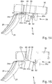
- the disassembly of the LED light module 20 from the optics unit 24 is described below with reference to FIG Figures 12 to 15 explained in more detail. It is basically carried out in the reverse order of assembly.
- the LED light module 20 is first moved forward in the positive x direction against the spring force of the at least one spring element 50 relative to the optical unit 24 (cf. Figure 12 ; Arrow 72). This releases the active engagement between the stop elements 46, 48 of the light module 20 and the corresponding referencing geometry 40, 42, 44 of the optical unit 24.
- the LED light module 20 is pivoted clockwise about the axis of rotation, the front section of the light module 20 moved in the positive z direction (cf. Figure 12 ; Arrow 74).
- the swivel movement is only a few degrees of angle, in any case significantly less than in previously known solutions, where the swivel movement is at least 15 °.
- the stop elements 46, 48 are arranged above the referencing geometry 40, 42, 44 (cf. Figure 13 )
- the inclined LED light module 20 is moved translationally in the negative x-direction (arrow 76).
- the rear edge section 24c of the base plate 24a of the optical unit 24 emerges from the holding arm 56a of the first holding element 56 or from the holding arms 52a, 54a of the second holding elements 52, 54 and the active surface 56b of the holding arm 56a slides along the underside of the projection 24b in Direction of the rear edge section and the active surfaces 52b, 54b of the holding arms 52a, 54a slide along the underside of the base plate 24a in the direction of the rear edge section 24c (cf. Figure 14 ).
- the LED light module 20 can then be lifted off the optics unit 24 (cf. Figure 15 ); disassembly is now complete.
Abstract
Die Erfindung betrifft ein LED-Scheinwerfermodul (12) umfassend ein LED-Lichtmodul (20) und eine davon separate Optikeinheit (24). Das Lichtmodul (20) weist eine Platine (28) mit einer LED-Lichtquelle (22) zum Aussenden von Licht und einen separaten Adapter (32) zur lösbaren Befestigung des LED-Lichtmoduls (20) an der Optikeinheit (24) auf. Die Optikeinheit umfasst ein optisches Umlenkelement (26) zum Bündeln und Umlenken des ausgesandten Lichts in eine Lichtaustrittsrichtung (6). Es wird vorgeschlagen, dass die Platine (28) und der Adapter (32) aneinander befestigt sind. Das LED-Lichtmodul (20) hat mit einer Referenzier-Geometrie (40, 42, 44) der Optikeinheit (24) zusammenwirkende Anschlagelemente (46, 48) zur lagegenauen Positionierung des LED-Lichtmoduls (20) relativ zu der Optikeinheit (24) in einer xy-Ebene. Der Adapter (32) ein Federelement (50), welches bei montiertem LED-Lichtmodul (20) die Anschlagelemente (46, 48) gegen die Referenzier-Geometrie (40, 42, 44) drückt. Der Adapter (32) umfasst mindestens ein in einem Anlenkbereich (78) angelenktes Halteelement (52, 54, 56) mit einem in einer z-Richtung federnden Haltearm (52a, 54a, 56a) und einer darauf ausgebildeten sich in der xy-Ebene erstreckenden Wirkfläche (52b, 54b, 56b), die das lagegenau positionierte LED-Lichtmodul (20) in z-Richtung an der Optikeinheit (24) hält. Die Wirkfläche (52b, 54b, 56b) wirkt auf einen Teilbereich der Optikeinheit (24).The invention relates to an LED headlight module (12) comprising an LED light module (20) and an optical unit (24) separate therefrom. The light module (20) has a circuit board (28) with an LED light source (22) for emitting light and a separate adapter (32) for detachably fastening the LED light module (20) to the optics unit (24). The optical unit comprises an optical deflection element (26) for bundling and deflecting the emitted light in a light exit direction (6). It is proposed that the board (28) and the adapter (32) are attached to one another. The LED light module (20) has stop elements (46, 48) which interact with a referencing geometry (40, 42, 44) of the optical unit (24) for the positionally accurate positioning of the LED light module (20) relative to the optical unit (24) in an xy plane. The adapter (32) is a spring element (50) which, when the LED light module (20) is mounted, presses the stop elements (46, 48) against the reference geometry (40, 42, 44). The adapter (32) comprises at least one holding element (52, 54, 56) articulated in an articulation area (78) with a holding arm (52a, 54a, 56a) resilient in a z-direction and one extending thereon in the xy plane Effective surface (52b, 54b, 56b) that holds the precisely positioned LED light module (20) in the z direction on the optics unit (24). The active surface (52b, 54b, 56b) acts on a partial area of the optical unit (24).
Description
Die vorliegende Erfindung betrifft ein LED-Scheinwerfermodul gemäß dem Oberbegriff des Anspruchs 1, vorzugsweise zur Verwendung in einem Kraftfahrzeug zur Erzeugung einer Hauptlichtfunktion, sowie ein LED-Lichtmodul zur Verwendung in einem solchen LED-Scheinwerfermodul. Ferner betrifft die Erfindung ein Verfahren zur Montage eines LED-Lichtmoduls eines LED-Scheinwerfermoduls auf einer von dem LED-Lichtmodul separaten Optikeinheit des LED-Scheinwerfermoduls gemäß dem Oberbegriff des Anspruchs 18. Bei den bekannten LED-Lichtmodulen für Scheinwerfer sind die LED-Lichtquellen in der Regel nicht oder nur mit erheblichem Aufwand austauschbar. Zudem gestaltet sich die lagegenaue Montage des LED-Lichtmoduls an der Optikeinheit im Rahmen der Herstellung von LED-Scheinwerfermodulen sehr aufwendig und fehleranfällig.The present invention relates to an LED headlight module according to the preamble of claim 1, preferably for use in a motor vehicle for generating a main light function, and an LED light module for use in such an LED headlight module. Furthermore, the invention relates to a method for mounting an LED light module of an LED headlight module on an optical unit of the LED headlight module separate from the LED light module according to the preamble of claim 18. In the known LED light modules for headlights, the LED light sources are in generally not exchangeable or only with considerable effort. In addition, the precise installation of the LED light module on the optics unit is very complex and error-prone when producing LED headlight modules.
Ein LED-Scheinwerfermodul der eingangs genannten Art mit austauschbaren LED-Lichtquellen ist bspw. aus der
Dabei ist es nachteilig, dass der Kühlkörper zweiteilig ausgeführt ist, um eine Wechselbarkeit der Lichtquelle zu erreichen. Dadurch wird die Effizienz des Kühlkörpers verringert und es entsteht ein erhöhter Teileaufwand. Zudem ergibt sich durch das Erfordernis der Befestigung des Umlenkelements an dem einen Teil des Kühlkörpers mittels Schrauben ein erhöhter Montageaufwand. Ein weiterer Nachteil des bekannten LED-Scheinwerfermoduls besteht darin, dass die Positionierungsstifte und die entsprechenden Positionierungsvertiefungen an bzw. in den beiden Teilen des Kühlkörpers ausgebildet werden müssen. Konstruktionsbedingt müssen beide Teile des Kühlkörpers als Aluminium-Druckgussteile ausgeführt sein, wodurch sich ein erhöhter Kostenaufwand ergibt.It is disadvantageous that the heat sink is designed in two parts in order to achieve interchangeability of the light source. This reduces the efficiency of the heat sink and increases the number of parts. In addition, the requirement for fastening the deflecting element to one part of the heat sink by means of screws results in increased assembly effort. Another disadvantage of the known LED headlight module is that the positioning pins and the corresponding positioning recesses have to be formed on or in the two parts of the heat sink. Due to the design, both parts of the heat sink must be designed as die-cast aluminum parts, which results in increased costs.
Ferner ist aus der nachveröffentlichten
Zur Montage wird bei dem LED-Scheinwerfermodul aus der
Problematisch ist dabei jedoch der relativ große Platzbedarf, der für die Schwenkbewegung des Lichtmoduls relativ zu der Optikeinheit bei der Montage bzw. Demontage erforderlich ist. Ferner kann es beim schrägen Aufsetzen der Optikeinheit auf den vorderen Rand der Grundplatte und beim Einführen des vorderen Rands der Grundplatte in die Hinterschneidungen zu einer Beschädigung des Reflektors im Sichtbereich (z.B. Verkratzen oder Beschädigung einer Reflexionsfläche des Reflektors) kommen. Schließlich müssen die Federwege der Rasthaken und des Federelements aus Platzgründen relativ kurz ausgebildet sein, so dass es im Rahmen der Montage des Lichtmoduls an der Optikeinheit zu einer Überdehnung der Rasthaken und des Federelements kommen kann.However, the relatively large space requirement, which is required for the pivoting movement of the light module relative to the optical unit during assembly or disassembly, is problematic. Furthermore, when the optical unit is placed at an angle on the front edge of the base plate and when the front edge of the base plate is inserted into the undercuts, the reflector can be damaged in the field of vision (e.g. scratching or damage to a reflection surface of the reflector). Finally, the spring travel of the locking hooks and the spring element must be made relatively short for reasons of space, so that the locking hooks and the spring element can be overstretched when the light module is mounted on the optical unit.
Ausgehend von dem beschriebenen Stand der Technik liegt der vorliegenden Erfindung deshalb die Aufgabe zugrunde, ein LED-Scheinwerfermodul mit wechselbarer LED-Lichtquelle vorzuschlagen, bei dem einerseits eine Montage bzw. Demontage einfach, schnell und mit möglichst wenig Platzbedarf möglich ist und andererseits die LED-Lichtquelle nach der Montage möglichst lagegenau, sicher und zuverlässig bezüglich einer Optikeinheit des Scheinwerfermoduls gehalten ist.Starting from the described prior art, the present invention is therefore based on the object of proposing an LED headlight module with exchangeable LED light source in which, on the one hand, assembly and disassembly is simple, quick and takes up as little space as possible and on the other hand, the LED light source is held as precisely as possible after installation, safely and reliably with respect to an optical unit of the headlight module.
Zur Lösung dieser Aufgabe wird ein LED-Scheinwerfermodul für einen Kraftfahrzeugscheinwerfer, mit den Merkmalen des Anspruchs 1 vorgeschlagen. Insbesondere wird ein LED-Scheinwerfermodul vorgeschlagen, das ein LED-Lichtmodul und eine von dem LED-Lichtmodul separate Optikeinheit umfasst. Das LED-Lichtmodul weist eine Platine, auf der mindestens eine LED-Lichtquelle zum Aussenden von Licht befestigt und elektrisch kontaktiert ist, und einen von der Platine separaten Adapter zur lösbaren Befestigung des LED-Lichtmoduls an der Optikeinheit auf. Die Optikeinheit weist mindestens ein optisches Umlenkelement zum Bündeln und Umlenken zumindest eines Teils des ausgesandten Lichts in eine Lichtaustrittsrichtung des LED-Scheinwerfermoduls auf. Die Platine und der Adapter sind zumindest mittelbar starr aneinander befestigt. Das LED-Lichtmodul weist mindestens ein Anschlagelement auf, das an dem LED-Lichtmodul derart angeordnet und ausgebildet ist, dass es eine lagegenaue Positionierung des LED-Lichtmoduls relativ zu der Optikeinheit in einer xy-Ebene ermöglicht, indem es mit einer entsprechenden Referenzier-Geometrie der Optikeinheit zusammenwirkt. Der Adapter umfasst mindestens ein Federelement, welches bei montiertem LED-Lichtmodul das mindestens eine Anschlagelement des LED-Lichtmoduls zur lagegenauen Positionierung des LED-Lichtmoduls in der xy-Ebene gegen die Referenzier-Geometrie der Optikeinheit drückt. Der Adapter weist ferner eine Befestigungsanordnung zur lösbaren Befestigung des lagegenau positionierten LED-Lichtmoduls in z-Richtung an der Optikeinheit auf. Die Befestigungsanordnung umfasst mindestens ein an dem Adapter in einem Anlenkbereich angelenktes erstes Halteelement mit einem in einer z-Richtung federnden Haltearm und einer darauf ausgebildeten Wirkfläche aufweist, die sich im Wesentlichen in einer Ebene parallel zur xy-Ebene erstreckt und die das lagegenau positionierte LED-Lichtmodul in z-Richtung an der Optikeinheit hält. Die Wirkfläche wirkt auf einen Teilbereich der Optikeinheit, der bei lagegenau positioniertem LED-Lichtmodul gegenüber dem Teilbereich der Optikeinheit liegt, auf den das mindestens eine Anschlagelement wirkt.To solve this problem, an LED headlight module for a motor vehicle headlight is proposed with the features of claim 1. In particular, an LED headlight module is proposed which comprises an LED light module and an optical unit separate from the LED light module. The LED light module has a circuit board on which at least one LED light source for emitting light is fastened and electrically contacted, and an adapter separate from the circuit board for releasably fastening the LED light module to the optical unit. The optical unit has at least one optical deflecting element for bundling and deflecting at least some of the emitted light in a light exit direction of the LED headlight module. The circuit board and the adapter are at least indirectly rigidly attached to one another. The LED light module has at least one stop element which is arranged and designed on the LED light module in such a way that it enables the LED light module to be positioned in an exact position relative to the optical unit in an xy plane by using a corresponding reference geometry the optical unit interacts. The adapter comprises at least one spring element which, when the LED light module is mounted, presses the at least one stop element of the LED light module to position the LED light module in the xy plane against the reference geometry of the optical unit. The adapter also has a fastening arrangement for releasably fastening the precisely positioned LED light module in the z direction on the optical unit. The fastening arrangement comprises at least one first holding element which is articulated on the adapter in an articulation area and has a holding arm which is resilient in a z-direction and an active surface formed thereon, which extends essentially in a plane parallel to the xy plane and which has the LED positioned exactly in position. Light module holds in the z direction on the optical unit. The active surface acts on a partial area of the optical unit which, when the LED light module is positioned precisely, lies opposite the partial area of the optical unit on which the at least one stop element acts.
Das LED-Lichtmodul des erfindungsgemäßen LED-Scheinwerfermoduls umfasst eine Platine, und einen Adapter zur Befestigung des LED-Lichtmoduls an der Optikeinheit des LED-Scheinwerfermoduls. Das Umlenkelement der Optikeinheit ist bspw. als ein Reflektor mit einer spiegelnden Reflexionsfläche auf einer in Lichtaustrittsrichtung gerichteten Seite des Reflektors ausgebildet. Der Adapter kann aus Kunststoff oder einem Metallblech, insbesondere einem Federstahlblech, gefertigt sein. Der Adapter kann auch aus einem Materialmix oder aus mehreren Bauteilen aus unterschiedlichen Materialien (z.B. Kunststoff und Federstahl) bestehen. Bevorzugt umfasst das LED-Lichtmodul auch einen Kühlkörper, vorzugsweise in Form eines einteiligen Blech-Biegeteils bspw. aus einem Federstahlblech.The LED light module of the LED headlight module according to the invention comprises a circuit board and an adapter for fastening the LED light module to the optical unit of the LED headlight module. The deflecting element of the optical unit is designed, for example, as a reflector with a specular reflection surface on a side of the reflector directed in the light exit direction. The adapter can be made of plastic or a metal sheet, in particular a spring steel sheet. The adapter can also consist of a material mix or of several components made of different materials (e.g. plastic and spring steel). The LED light module preferably also comprises a heat sink, preferably in the form of a one-piece bent sheet metal part, for example made of a spring steel sheet.
Der Adapter und die Platine sind starr aneinander befestigt. Vorzugsweise sind sie gemeinsam an einem Kühlkörper des LED-Lichtmoduls befestigt. Beispielsweise kann der Adapter mittels Schrauben oder auf andere Weise an einem Kühlkörper befestigt werden, wobei die Platine zwischen dem Adapter und dem Kühlkörper eingespannt ist. Da die Platine, der Adapter und der Kühlkörper dann starr miteinander verbunden sind, könnten die verschiedenen Elemente zur lagegenauen Positionierung und Befestigung des LED-Lichtmoduls relativ zu der Optikeinheit grundsätzlich an einem beliebigen Teil (Platine, Adapter oder Kühlkörper) des Lichtmoduls ausgebildet oder angeordnet sein. Der Adapter kann einfach und kostengünstig hergestellt werden und kann problemlos mit geeigneten Elemente versehen werden, welche eine lagegenaue Positionierung und/oder Befestigung des LED-Lichtmoduls an der Optikeinheit ermöglichen. Dadurch ergibt sich ein besonders einfacher und kostengünstiger Aufbau des LED-Lichtmoduls.The adapter and the board are rigidly attached to each other. They are preferably fastened together on a heat sink of the LED light module. For example, the adapter can be fastened to a heat sink by means of screws or in some other way, the circuit board being clamped between the adapter and the heat sink. Since the circuit board, the adapter and the heat sink are then rigidly connected to one another, the various elements for the precise positioning and fastening of the LED light module relative to the optical unit could in principle be formed or arranged on any part (circuit board, adapter or heat sink) of the light module . The adapter can be produced easily and inexpensively and can be provided with suitable elements without any problems, which enable the LED light module to be positioned and / or attached to the optical unit in a precise position. This results in a particularly simple and inexpensive construction of the LED light module.
Gemäß einer vorteilhaften Weiterbildung wird vorgeschlagen, dass die Befestigungsanordnung außerdem mindestens ein an dem Adapter in einem Anlenkbereich angelenktes zweites Halteelement mit einem in einer z-Richtung federnden Haltearm und einer darauf ausgebildeten Wirkfläche aufweist, die sich im Wesentlichen in einer Ebene parallel zu der xy-Ebene erstreckt und die das lagegenau positionierte LED-Lichtmodul in z-Richtung an der Optikeinheit hält, wobei die Wirkfläche auf einen Teilbereich der Optikeinheit wirkt, der bei lagegenau positioniertem LED-Lichtmodul zwischen dem Teilbereich der Optikeinheit, auf den das mindestens eine erste Halteelement wirkt, und dem Teilbereich der Optikeinheit liegt, auf den das mindestens eine Anschlagelement wirkt. Dem Anlenkbereich des Halteelements an dem Adapter und dem mindestens einen Anschlagelement des LED-Lichtmoduls liegt. Die zweiten Halteelemente unterscheiden sich von den ersten Halteelementen insbesondere dadurch, dass sie auf unterschiedliche Teilbereiche des Optikelements wirken, um das LED-Lichtmodul sicher in z-Richtung an dem Optikelement lösbar zu halten. Während die Wirkfläche des mindestens einen ersten Halteelements eher in einem Randbereich auf eine Oberfläche der Grundplatte der Optikeinheit wirkt, wirkt die Wirkfläche des mindestens einen zweiten Halteelements aufgrund der längeren Haltearme eher in einem Abstand zu dem Randbereich auf die Oberfläche der Grundplatte.According to an advantageous development, it is proposed that the fastening arrangement also has at least one second holding element articulated on the adapter in an articulation area with a holding arm resilient in a z direction and an active surface formed thereon, which is essentially in a plane parallel to the xy- Plane extends and which holds the precisely positioned LED light module in the z-direction on the optical unit, the active surface acting on a partial area of the optical unit, which in the precisely positioned LED light module between the partial area of the optical unit, on the the at least one first holding element acts, and lies in the partial area of the optical unit on which the at least one stop element acts. The articulation area of the holding element lies on the adapter and the at least one stop element of the LED light module. The second holding elements differ from the first holding elements in particular in that they act on different partial areas of the optical element in order to hold the LED light module securely detachably in the z direction on the optical element. While the active surface of the at least one first holding element acts more in an edge region on a surface of the base plate of the optical unit, the active surface of the at least one second holding element acts on the surface of the base plate at a distance from the edge region rather than at a distance from the edge region.
Gemäß einer bevorzugten Ausführungsform der Erfindung wird vorgeschlagen, dass sämtliche Halteelemente, welche das lagegenau positionierte LED-Lichtmodul in z-Richtung an der Optikeinheit lösbar befestigen, auf der gleichen Seite des Adapters in dem Anlenkbereich an dem Adapter angelenkt sind.According to a preferred embodiment of the invention, it is proposed that all holding elements, which releasably attach the precisely positioned LED light module in the z-direction to the optical unit, are articulated on the adapter on the same side of the adapter in the articulation area.
Bei dem erfindungsgemäßen LED-Scheinwerfermodul wird das LED-Lichtmodul vorzugsweise von hinten schräg auf einen hinteren Rand einer Grundplatte der Optikeinheit aufgesetzt. Dabei wird das Lichtmodul mit geringer Kraft so weit in Richtung des vorderen Randes der Grundplatte (in Lichtaustrittsrichtung des Scheinwerfermoduls) entgegen der Kraft des mindestens einen Federelements gedrückt, bis das mindestens eine Anschlagelement über die Referenzier-Geometrie der Optikeinheit am vorderen Rand der Grundplatte geschoben und das LED-Lichtmodul um eine entlang des hinteren Rands der Grundplatte verlaufende Drehachse geschwenkt werden kann. Beim Aufsetzen des LED-Lichtmoduls auf die Optikeinheit gleitet der federnde Haltearm des oder der Halteelemente mit seiner Wirkfläche ausgehend von dem hinteren Rand der Grundplatte auf der Unterseite der Grundplatte entlang, bis er den Teilbereich der Grundplatte erreicht, über den er auf die Optikeinheit wirkt und aufgrund seiner Federwirkung das LED-Lichtmodul und die Optikeinheit in z-Richtung gegeneinander drückt. Durch die Federkraft des mindestens einen Federelements wird das mindestens eine Anschlagelement des LED-Lichtmoduls gegen die Referenzier-Geometrie der Optikeinheit gedrückt, so dass das LED-Lichtmodul auch in der xy-Ebene relativ zu der Optikeinheit lagegenau positioniert und gehalten ist.In the LED headlight module according to the invention, the LED light module is preferably placed obliquely from behind on a rear edge of a base plate of the optical unit. The light module is pressed with low force so far in the direction of the front edge of the base plate (in the light exit direction of the headlight module) against the force of the at least one spring element until the at least one stop element is pushed over the referencing geometry of the optical unit at the front edge of the base plate and the LED light module can be pivoted about an axis of rotation running along the rear edge of the base plate. When the LED light module is placed on the optical unit, the resilient holding arm of the holding element or elements slides along with its active surface, starting from the rear edge of the base plate on the underside of the base plate, until it reaches the portion of the base plate via which it acts on the optical unit and due to its spring action, the LED light module and the optical unit press against each other in the z direction. The spring force of the at least one spring element pushes the at least one stop element of the LED light module against the referencing geometry of the optical unit, so that the LED light module is also positioned and held in the xy plane relative to the optical unit.
Mit dem erfindungsgemäßen LED-Scheinwerfermodul ist eine besonders einfache und positionsgenaue Montage des LED-Lichtmoduls bezüglich der Optikeinheit bzw. dem Umlenkelement ohne zusätzliche oder separate Montage-Vorrichtungen möglich. Zudem ist eine einfache Demontage bzw. ein einfacher Austausch des LED-Lichtmoduls möglich. Dabei ist es besonders vorteilhaft, dass für die Montage bzw. Demontage des Lichtmoduls nur ein sehr kleiner Platz für die Schwenkbewegung erforderlich ist. Ferner kann es zu keiner Beschädigung des Reflektors im Sichtbereich (bspw. im Bereich einer spiegelnden Reflexionsfläche oder sichtbarer Blenden) kommen, da das Lichtmodul auf den außerhalb des Sichtbereichs liegenden hinteren Rand der Grundplatte der Optikeinheit aufgesetzt wird. Schließlich ist der Haltearm des oder der Halteelemente in z-Richtung federnd ausgebildet, wobei der Federweg des Haltearms relativ lang ausgebildet ist, so dass eine Überdehnung des Haltearms des oder der Halteelemente beim Montieren des LED-Lichtmoduls an der Optikeinheit ausgeschlossen ist.With the LED headlight module according to the invention, a particularly simple and positionally accurate mounting of the LED light module with respect to the optical unit or the deflection element is possible without additional or separate mounting devices. In addition, simple disassembly or replacement of the LED light module is possible. It is particularly advantageous that only a very small space for the pivoting movement is required for the assembly or disassembly of the light module. Furthermore, there can be no damage to the reflector in the viewing area (for example in the area of a reflecting reflection surface or visible diaphragms), since the light module is placed on the rear edge of the base plate of the optical unit that is outside the viewing area. Finally, the holding arm of the holding element or elements is designed to be resilient in the z direction, the spring travel of the holding arm being designed to be relatively long, so that an overextension of the holding arm of the holding element or elements is excluded when the LED light module is mounted on the optical unit.
Das erfindungsgemäße LED-Scheinwerfermodul weist eine robuste Referenzier-Geometrie (vgl. bspw. auch die
Die Referenzier-Geometrie der Optikeinheit ist ausgebildet, im Zusammenwirken mit den Anschlagelementen des LED-Lichtmoduls, dieses in einer xy-Ebene relativ zu der Optikeinheit lagegenau zu positionieren. Die Referenzier-Geometrie ist vorzugsweise an einem vorderen Rand einer Grundplatte der Optikeinheit ausgebildet. Die Referenzier-Geometrie umfasst insbesondere eine in x-Richtung wirkende erste Anschlagfläche, die sich in der y-Richtung erstreckt, sowie in y-Richtung versetzt zu der ersten Anschlagfläche zwei weitere V-förmig zueinander stehende Anschlagflächen, die jeweils in x- und in y-Richtung wirken. Die erste Anschlagfläche der Referenzier-Geometrie wirkt mit einem entsprechenden ersten Anschlagelement des LED-Lichtmoduls zusammen. Die beiden weiteren V-förmig zueinander stehenden Anschlagflächen wirken mit einem entsprechenden anderen Anschlagelement des LED-Lichtmoduls zusammen.The referencing geometry of the optical unit is designed, in cooperation with the stop elements of the LED light module, to position it in an xy plane relative to the optical unit. The referencing geometry is preferably formed on a front edge of a base plate of the optical unit. The referencing geometry includes, in particular, a first stop surface acting in the x direction, which extends in the y direction, and in the y direction offset from the first stop surface, two further V-shaped stop surfaces, each in x and in act in the y direction. The first stop surface of the referencing geometry interacts with a corresponding first stop element of the LED light module. The two further V-shaped stop faces interact with a corresponding other stop element of the LED light module.
Das LED-Lichtmodul wird vormontiert, indem der Adapter zusammen mit der Platine an dem Kühlkörper befestigt wird. Dies kann insbesondere mittels Schrauben geschehen. Die Platine kann bei an dem Kühlkörper befestigtem Adapter zwischen dem Adapter und dem Kühlkörper eingespannt und so mittelbar an dem Adapter und dem Kühlkörper befestigt sein. Es ist auch denkbar, dass die Platine unabhängig von dem Adapter, bspw. mittels mindestens einer Schraube, an dem Kühlkörper befestigt wird. In den Adapter integriert sind sowohl Positionierungsmittel zur lagegenauen Anordnung des Adapters relativ zu der LED-Lichtquelle bzw. der Leiterplatte als auch die Anschlagelemente, die zur lagegenauen Positionierung relativ zu der Optikeinheit mit der Referenzier-Geometrie zusammenwirken. Darüber hinaus sind das mindestens eine Federelement sowie die Haltearme der ersten und - sofern vorhanden - zweiten Halteelemente einstückig mit dem Adapter ausgebildet. Wenn das LED-Lichtmodul relativ zu der Optikeinheit mit dem Umlenkelement in der xy-Ebene lagegenau positioniert und in der z-Richtung ordnungsgemäß positioniert und gehalten ist, befindet sich die LED-Lichtquelle in der geforderten Position und Ausrichtung relativ zu dem Umlenkelement (z.B. der Reflexionsfläche eines Reflektors), so dass das LED-Scheinwerfermodul die vorgesehene Lichtverteilung erzeugen kann.The LED light module is pre-assembled by attaching the adapter to the heat sink together with the circuit board. This can be done in particular by means of screws. With the adapter attached to the heat sink, the circuit board can be clamped between the adapter and the heat sink and thus indirectly attached to the adapter and the heat sink. It is also conceivable that the circuit board is attached to the heat sink independently of the adapter, for example by means of at least one screw. Integrated in the adapter are both positioning means for the precise positioning of the adapter relative to the LED light source or the printed circuit board, as well as the stop elements which interact with the reference geometry for precise positioning relative to the optical unit. In addition, the at least one spring element and the holding arms of the first and - if present - second holding elements are integrally formed with the adapter. If the LED light module is positioned exactly in relation to the optical unit with the deflecting element in the xy plane and is correctly positioned and held in the z direction, the LED light source is in the required position and Alignment relative to the deflection element (for example the reflection surface of a reflector) so that the LED headlight module can generate the intended light distribution.
Alternativ ist es insbesondere bei einem aus Federstahl gefertigten Adapter auch denkbar, dass Teilbereiche des Adapters, bspw. in Form von Biegelaschen, durch entsprechende Öffnungen, die in dem Kühlkörper ausgebildet sind, hindurchgeführt und auf der Rückseite des Kühlkörpers umgebogen werden, um im Rahmen der Vormontage des LED-Lichtmoduls den Adapter zusammen mit der Platine an dem Kühlkörper auf andere Weise als durch eine oder mehrere Schrauben zu befestigen.Alternatively, it is also conceivable, in particular in the case of an adapter made of spring steel, that partial regions of the adapter, for example in the form of bending tabs, are passed through corresponding openings formed in the heat sink and bent over on the rear side of the heat sink in order to Pre-assembly of the LED light module to fix the adapter together with the circuit board to the heat sink in another way than by one or more screws.
Anschließend wird das vormontierte LED-Lichtmodul manuell schräg auf die Optikeinheit aufgesetzt, relativ zu dieser geschwenkt und dann mittels des Haltearms des oder der Halteelemente automatisch in der lagegenau definierten Position an der Optikeinheit gehalten. Beim Aufsetzen des LED-Lichtmoduls auf die Optikeinheit, insbesondere auf den hinteren Randbereich einer Grundplatte der Optikeinheit, führt das LED-Lichtmodul eine näherungsweise translatorische Bewegung in eine positive x-Richtung und in etwa parallel zu einer Flächenerstreckung der Grundplatte der Optikeinheit aus, bis sich die Anschlagelemente des LED-Lichtmoduls vor der Referenzier-Geometrie der Optikeinheit befinden, so dass die Optikeinheit dann im Rahmen der Schwenkbewegung um eine Drehachse, die näherungsweise durch den hinteren Randbereich der Grundplatte gebildet ist, geschwenkt werden kann. Dabei gelangen die Anschlagelemente in einen Wirkeingriff mit der Referenzier-Geometrie. Die Drehachse verläuft vorzugsweise parallel zur y-Achse, wobei sich im Rahmen der Schwenkbewegung ein vorderer Abschnitt des Lichtmoduls in Richtung der Optikeinheit bewegt. Eine Federkraft des mindestens einen Haltearms des oder der Halteelemente wirkt in Richtung der Schwenkbewegung. Nach Beendigung der Schwenkbewegung verläuft die Platine des Lichtmoduls vorzugsweise parallel zu der Grundplatte der Optikeinheit.The preassembled LED light module is then manually placed obliquely on the optical unit, pivoted relative to it and then automatically held in the precisely defined position on the optical unit by means of the holding arm of the holding element or elements. When the LED light module is placed on the optical unit, in particular on the rear edge area of a base plate of the optical unit, the LED light module executes an approximately translatory movement in a positive x-direction and approximately parallel to a surface extension of the base plate of the optical unit until the stop elements of the LED light module are located in front of the referencing geometry of the optical unit, so that the optical unit can then be pivoted about an axis of rotation, which is approximately formed by the rear edge region of the base plate, as part of the pivoting movement. The stop elements come into active engagement with the referencing geometry. The axis of rotation preferably runs parallel to the y-axis, a front section of the light module moving in the direction of the optical unit as part of the pivoting movement. A spring force of the at least one holding arm of the holding element or elements acts in the direction of the pivoting movement. After the swiveling movement has ended, the circuit board of the light module preferably runs parallel to the base plate of the optical unit.
Das Lichtmodul kann nun losgelassen werden, wobei dann insbesondere zwei Dinge geschehen: Das mindestens eine Federelement drückt das mindestens eine Anschlagelement des LED-Lichtmoduls gegen die Referenzier-Geometrie der Optikeinheit (und sorgt so für eine lagegenaue Positionierung des Lichtmoduls relativ zu der Optikeinheit in der xy-Ebene) und der mindestens eine in z-Richtung federnde Haltearm des oder der Halteelemente drückt das Lichtmodul und die Optikeinheit gegeneinander (und sorgt so für eine lagegenaue Positionierung in z-Richtung). Damit ist das LED-Lichtmodul im dreidimensionalen Raum relativ zu der Optikeinheit positioniert und gehalten.The light module can now be released, two things then happening in particular: the at least one spring element presses the at least one stop element of the LED light module against the referencing geometry of the Optics unit (and thus ensures that the light module is positioned precisely in relation to the optics unit in the xy plane) and the at least one holding arm of the holding element or springs, which resilient in the z direction, presses the light module and the optics unit against each other (and thus ensures exact positioning) in the z direction). The LED light module is thus positioned and held in three-dimensional space relative to the optical unit.
Das LED-Scheinwerfermodul hat nicht nur den Vorteil, dass eine defekte LED-Lichtquelle (zusammen mit dem LED-Lichtmodul) ausgewechselt werden kann, sondern auch, dass eine Montage des LED-Scheinwerfermoduls beim Hersteller des Scheinwerfermoduls, insbesondere eine lagerichtige und lagegenaue Befestigung des LED-Lichtmoduls an der Optikeinheit, schnell und zuverlässig auch von ungelernten Personen oder sogar vollautomatisiert mittels eines Montageroboters durchgeführt werden kann. Der Begriff der Lage umfasst im Sinne der vorliegenden Erfindung sowohl eine Position als auch eine Ausrichtung des Lichtmoduls relativ zu der Optikeinheit.The LED headlight module not only has the advantage that a defective LED light source (together with the LED light module) can be replaced, but also that the LED headlight module is installed by the manufacturer of the headlight module, in particular that the positioner is fixed correctly and in position LED light module on the optics unit, can be carried out quickly and reliably even by unskilled people or even fully automated using an assembly robot. In the context of the present invention, the term position encompasses both a position and an orientation of the light module relative to the optical unit.
Im Rahmen einer Demontage des LED-Scheinwerfermoduls wird zunächst eine translatorische Bewegung des Lichtmoduls relativ zu der Optikeinheit in positive x-Richtung entgegen der Federkraft des mindestens einen Federelements ausgeführt, so dass sich die Anschlagelemente von der Referenzier-Geometrie abheben. Dann wird eine Schwenkbewegung des Lichtmoduls relativ zu der Optikeinheit um die Drehachse durchgeführt, wobei sich im Rahmen der Schwenkbewegung ein vorderer Abschnitt des Lichtmoduls von der Optikeinheit weg bewegt. Die Federkraft des mindestens einen Haltearms des oder der Halteelemente wirkt entgegen dieser Schwenkbewegung. Sobald sich im Verlauf der Schwenkbewegung das mindestens eine Anschlagelement oberhalb der Grundplatte der Optikeinheit befindet und das mindestens eine Anschlagelement nicht mehr mit der Referenzier-Geometrie in einem Wirkeingriff steht, wird das LED-Lichtmodul in einer näherungsweise translatorischen Bewegung in eine negative x-Richtung und in etwa parallel zu einer Flächenerstreckung der Grundplatte des Optikelements bewegt, bis die Wirkfläche des mindestens einen Haltearms des oder der Halteelemente nicht mehr mit der Optikeinheit in Kontakt steht. Dann kann das Lichtmodul von der Optikeinheit abgenommen und ausgetauscht werden.As part of a disassembly of the LED headlight module, a translatory movement of the light module relative to the optical unit in the positive x direction is initially carried out against the spring force of the at least one spring element, so that the stop elements stand out from the referencing geometry. A pivoting movement of the light module relative to the optics unit is then carried out about the axis of rotation, a front section of the light module moving away from the optics unit as part of the pivoting movement. The spring force of the at least one holding arm of the holding element or elements acts counter to this pivoting movement. As soon as the at least one stop element is located above the base plate of the optical unit in the course of the swivel movement and the at least one stop element is no longer in operative engagement with the referencing geometry, the LED light module is moved in an approximately translatory movement in a negative x-direction and moved approximately parallel to a surface extension of the base plate of the optical element until the effective surface of the at least one holding arm of the holding element or elements no longer coincides with the Optics unit is in contact. The light module can then be removed from the optics unit and replaced.
Bei der vorliegenden Erfindung sind keinerlei Halte- oder Federelemente oder sonstige Befestigungs- oder Halteelemente vorgesehen, die den vorderen Rand einer Grundplatte der Optikeinheit umgreifen oder halten. Alle Halte- oder Federelemente stehen mit dem hinteren Rand der Grundplatte oder allenfalls einem Teilbereich der Grundplatte zwischen dem hinteren und dem vorderen Rand in Wirkverbindung. Dabei ist an dem Adapter auf seiner im montierten Zustand des LED-Lichtmoduls nach hinten gerichteten Seite vorzugsweise das mindestens eine Federelement, sowie der mindestens eine Haltearm des oder der Halteelemente in dem Anlenkbereich derart angelenkt, dass sie insbesondere in y-Richtung nebeneinander angeordnet sind. An der nach vorne gerichteten Seite des Adapters sind keinerlei Halte- oder Federelemente angeordnet. Das erlaubt es, das vormontierte LED-Lichtmodul von hinten auf den hinteren Rand der Grundplatte der Optikeinheit aufzuschieben und es dann um die näherungsweise entlang des hinteren Rands der Grundplatte verlaufende Drehachse zu schwenken, wobei das LED-Lichtmodul am Ende der Schwenkbewegung trotzdem lagegenau, sicher und zuverlässig an der Optikeinheit positioniert und gehalten ist.In the present invention, no holding or spring elements or other fastening or holding elements are provided which grip around or hold the front edge of a base plate of the optical unit. All holding or spring elements are operatively connected to the rear edge of the base plate or, if necessary, a partial area of the base plate between the rear and the front edge. The at least one spring element, as well as the at least one holding arm of the holding element or elements in the articulation area are preferably articulated on the adapter on its rearward side in the assembled state of the LED light module in such a way that they are arranged next to one another in particular in the y direction. No holding or spring elements are arranged on the forward-facing side of the adapter. This allows the pre-assembled LED light module to be pushed onto the rear edge of the base plate of the optical unit from the rear and then pivoted about the axis of rotation running approximately along the rear edge of the base plate, the LED light module still being securely positioned at the end of the pivoting movement and is reliably positioned and held on the optical unit.
Weitere Merkmale und Vorteile der vorliegenden Erfindung werden nachfolgend anhand der Figuren näher erläutert. Dabei können die einzelnen, in den Figuren gezeigten und nachfolgend beschriebenen Merkmale der Erfindung auch einzeln oder in anderen Kombinationen als hier gezeigt und beschreiben erfindungswesentlich sein. Es zeigen:
- Figur 1
- ein erfindungsgemäßes LED-Lichtmodul gemäß einer ersten bevorzugten Ausführungsform in einer perspektivischen Ansicht von vorne und unten;
Figur 2- einen Ausschnitt eines erfindungsgemäßes LED-Scheinwerfermoduls mit dem LED-Lichtmodul aus
Figur 1 in einer perspektivischen Ansicht von hinten und unten; - Figur 3
- einen Ausschnitt des erfindungsgemäßen LED-Scheinwerfermoduls mit dem LED-Lichtmodul aus
Figur 1 in einer perspektivischen Ansicht von vorne und unten; Figur 4- einen Adapter des LED-Lichtmoduls aus
Figur 1 in einer perspektivischen Ansicht; - Figur 5
- Anschlagelemente des LED-Lichtmoduls aus
Figur 1 in einer perspektivischen Ansicht; Figur 6- eine Platine mit LED-Lichtquelle des LED-Lichtmoduls aus
Figur 1 in einer perspektivischen Ansicht; - Figur 7
- das vormontierte LED-Lichtmodul aus
Figur 1 in einer perspektivischen Ansicht; - Figuren 8-11
- verschiedene Phasen eines Montagevorgangs des LED-Lichtmoduls aus
Figur 1 auf einer Optikeinheit eines erfindungsgemäßen LED-Scheinwerfermoduls; - Figuren 12-15
- verschiedene Phasen eines Demontagevorgangs des LED-Lichtmoduls aus
Figur 1 von einer Optikeinheit eines erfindungsgemäßen LED-Scheinwerfermoduls; - Figur 16
- einen Ausschnitt des erfindungsgemäßen LED-Scheinwerfermoduls mit montiertem LED-Lichtmodul aus
Figur 1 in einer perspektivischen Ansicht von vorne und unten; - Figur 17
- einen Ausschnitt des erfindungsgemäßes LED-Scheinwerfermoduls mit montiertem LED-Lichtmodul aus
Figur 1 in einer perspektivischen Ansicht von hinten und unten; - Figur 18
- ein erfindungsgemäßes LED-Lichtmodul gemäß einer zweiten bevorzugten Ausführungsform in einer perspektivischen Ansicht von vorne und unten;
- Figuren 19-22
- verschiedene Phasen eines Montagevorgangs des LED-Lichtmoduls aus
Figur 18 auf einer Optikeinheit eines erfindungsgemäßen LED-Scheinwerfermoduls; und - Figur 23
- einen Kraftfahrzeugscheinwerfer mit einem erfindungsgemäßen LED-Scheinwerfermodul gemäß einer bevorzugten Ausführungsform in einer perspektivischen Ansicht.
- Figure 1
- an inventive LED light module according to a first preferred embodiment in a perspective view from the front and below;
- Figure 2
- a section of an inventive LED headlight module with the LED light module
Figure 1 in a perspective view from behind and below; - Figure 3
- a section of the LED headlight module according to the invention with the LED light module
Figure 1 in a perspective view from the front and below; - Figure 4
- an adapter of the LED light module
Figure 1 in a perspective view; - Figure 5
- Stop elements of the LED light module
Figure 1 in a perspective view; - Figure 6
- a circuit board with an LED light source from the LED light module
Figure 1 in a perspective view; - Figure 7
- the pre-assembled LED light module
Figure 1 in a perspective view; - Figures 8-11
- different phases of an assembly process of the LED light module
Figure 1 on an optical unit of an LED headlight module according to the invention; - Figures 12-15
- different phases of a disassembly process of the LED light module
Figure 1 from an optical unit of an LED headlight module according to the invention; - Figure 16
- a section of the LED headlight module according to the invention with a mounted LED light module
Figure 1 in a perspective view from the front and below; - Figure 17
- a section of the LED headlight module according to the invention with a mounted LED light module
Figure 1 in a perspective view from behind and below; - Figure 18
- an inventive LED light module according to a second preferred embodiment in a perspective view from the front and below;
- Figures 19-22
- different phases of an assembly process of the LED light module
Figure 18 on an optical unit of an LED headlight module according to the invention; and - Figure 23
- a motor vehicle headlight with an LED headlight module according to the invention according to a preferred embodiment in a perspective view.
In
Das LED-Scheinwerfermodul 12 dient zur Erzeugung einer beliebigen Scheinwerferfunktion (sog. Hauptlichtfunktion) oder eines Teils davon. Die Scheinwerferfunktion kann bspw. ein Abblendlicht, ein Fernlicht, ein Nebellicht, oder eine beliebige adaptive Lichtverteilung sein (z.B. in Form eines Schlechtwetterlichts, eines Stadtlichts, eines Landstraßen- oder Überlandlichts, eines Autobahnlichts, eines sog. Dauerfernlichts (auch als blendfreies Fernlicht oder Teilfernlicht bezeichnet) oder in Form eines sog. Markierungslichts).The
Zusätzlich zu dem dargestellten LED-Scheinwerfermodul 12 kann im Inneren des Gehäuses 4 des Scheinwerfers 2 auch noch mindestens ein weiteres Lichtmodul angeordnet sein, das entweder alleine eine andere Scheinwerferfunktion oder aber zusammen mit dem LED-Scheinwerfermodul 12 die Scheinwerferfunktion erzeugt. Die weiteren Lichtmodule können ebenfalls als LED-Module ausgebildet sein, oder aber auch andere Arten von Lichtquellen, bspw. eine Glühlampe, Gasentladungslampe, Laserlichtquelle etc., aufweisen. Selbstverständlich kann das mindestens eine weitere Lichtmodul auch als erfindungsgemäßes LED-Lichtmodul ausgebildet sein. Das mindestens eine weitere Lichtmodul kann als sog. Reflexionsmodul oder als Projektionsmodul ausgebildet sein.In addition to the
Bei einem Reflexionsmodul wird das von der Lichtquelle ausgesandte Licht mittels einer Primäroptik bspw. in der Form eines Reflektors gebündelt und in die Lichtaustrittsrichtung 6 umgelenkt. Die Lichtverteilung der resultierenden Scheinwerferfunktion, einschließlich einer möglicherweise vorhandenen Helldunkelgrenze, wird im Wesentlichen durch die Form einer Reflexionsfläche des Reflektors bestimmt. Diese hat in der Regel eine paraboloide Grundform. Durch optisch wirksame Elemente auf der Abdeckscheibe 10 und/oder der Reflexionsfläche kann eine Streuung, insbesondere in horizontaler Richtung, des hindurchtretenden Lichts bewirkt werden.In the case of a reflection module, the light emitted by the light source is bundled by means of primary optics, for example in the form of a reflector, and deflected in the
Bei einem Projektionsmodul wird das von der Lichtquelle ausgesandte Licht mittels einer Primäroptik bspw. in der Form eines Reflektors oder eines Linsenelements gebündelt und in die Lichtaustrittsrichtung 6 umgelenkt. Bei Verwendung eines Reflektors hat dieser in der Regel eine ellipsoide Grundform. Im Strahlengang des von der Primäroptik gebündelten Lichts ist eine Sekundäroptik angeordnet, bspw. in der Form einer Projektionslinse oder eines Projektionsreflektors, welche eine von der Primäroptik in einer Brennebene der Sekundäroptik erzeugte Zwischenlichtverteilung als resultierende Lichtverteilung der Scheinwerferfunktion auf der Fahrbahn vor dem Kraftfahrzeug abbildet. Im Strahlengang des von der Primäroptik gebündelten Lichts, vorzugsweise in der Brennebene der Sekundäroptik, die häufig mit der Brennebene der Primäroptik zusammenfällt, kann eine Blendenanordnung mit einer Kante angeordnet sein, welche einen Teil des gebündelten Lichts abschattet oder umlenkt und deren Kante von der Sekundäroptik als Helldunkelgrenze einer abgeblendeten Lichtverteilung auf die Fahrbahn projiziert wird.In the case of a projection module, the light emitted by the light source is bundled by means of primary optics, for example in the form of a reflector or a lens element, and deflected in the
Auch für das erfindungsgemäße LED-Scheinwerfermodul 12 gilt, dass dieses als ein Reflexionsmodul oder als ein Projektionsmodul ausgebildet sein kann. Allerdings ist in den Figuren eine Sekundäroptik, bspw. in der Form einer Projektionslinse, nicht gezeigt.It also applies to the
LED-Scheinwerfermodule 12 verwenden Halbleiterlichtquellen, insbesondere in der Form von einer oder mehreren Leuchtdioden (LEDs) 22, die zu einem LED-Chip 22a zusammengefasst sind. Halbleiterlichtquellen haben unter normalen Betriebsbedingungen in der Regel eine deutlich längere Lebensdauer als herkömmliche Lichtquellen. In der Praxis sind bisher noch keine LED-Scheinwerfermodule 12 bekannt, bei denen die LED-Lichtquellen 22 einfach, schnell und kostengünstig ausgetauscht werden können. Derzeit muss bei einem Defekt einer oder mehrerer LED-Lichtquellen 22 stets der gesamte Scheinwerfer 2 ausgetauscht werden, was mit einem erheblichen Aufwand und entsprechend hohen Kosten für Material und Arbeitszeit verbunden ist. Die bisher vorgeschlagenen Lösungen für LED-Scheinwerfermodule mit austauschbarer LED-Lichtquelle (z.B. aus der
Es wird ein LED-Scheinwerfermodul 12 vorgeschlagen, das ein austauschbares LED-Lichtmodul 20 aufweist, dessen Aufbau sowie dessen Montage/ Demontage nachfolgend anhand der
Das LED-Lichtmodul 20 umfasst eine Platine (printed circuit board, PCB) 28, auf der die mindestens eine LED-Lichtquelle 22 befestigt und elektrisch kontaktiert ist. In den gezeigten Beispielen sind auf einem LED-Chip 22a insgesamt drei LED-Lichtquellen 22 in y-Richtung nebeneinander angeordnet. Die Kontaktierung der LED-Lichtquellen 22 führt über Leiterbahnen der Platine 28 zu einem elektrischen Steckverbinder 28a. Bevorzugt ist der elektrische Steckverbinder 28a auf der Seite der Platine 28 angeordnet, auf der sich die LED-Lichtquellen 22 befinden. Über diesen wird mittels eines entsprechenden Steckverbinders (nicht dargestellt) ein Steuergerät zur Ansteuerung und/oder Energieversorgung der LED-Lichtquellen 22 an das LED-Lichtmodul 20 angeschlossen. Ferner umfasst das LED-Lichtmodul 20 einen Kühlkörper 30 aus einem Material mit einer guten Wärmeleitfähigkeit. Der Kühlkörper 30 ist insbesondere aus einem Metall mit einer Wärmeleitfähigkeit von über 70 W/(m·K), vorzugsweise von über 100 W/(m·K), ganz besonders bevorzugt von mindestens 235 W/(m·K) gefertigt. Als Material für den Kühlkörper 30 wird insbesondere Aluminium vorgeschlagen. Der Kühlkörper 30 ist vorzugsweise als ein einteiliges Blech-Biegeteil ausgebildet. Schließlich umfasst das LED-Lichtmodul 20 einen von dem Kühlkörper 30 und der Platine 28 separaten Adapter 32 zur lagegenauen Positionierung und lösbaren Befestigung des LED-Lichtmoduls 20 an der Optikeinheit 24 des LED-Scheinwerfermoduls 12.The
In den hier dargestellten Beispielen ist der Adapter 32 (vgl.
Bei der Befestigung des Adapters 32 an dem Kühlkörper 30 wird die Platine 28 dazwischen angeordnet, so dass sie bei befestigtem Adapter 32 zwischen einer Oberseite (die in positive z-Richtung gerichtete Fläche) des Adapters 32 und der Unterseite des Kühlkörpers 30 eingespannt und dadurch mittelbar an dem Adapter 32 und dem Kühlkörper 30 befestigt ist. Zur Positionierung der Platine 28 relativ zu dem Adapter 32 können geeignete Positionierungsmittel (Stifte und entsprechende Aussparungen oder Löcher) an der Platine 28 und dem Adapter 32 vorgesehen sein. Die Positionierungsmittel des Adapters 32 können auf einfache Weise im Rahmen der Herstellung des Adapters 32, bspw. beim Stanzen oder Biegen, in einem Stück mit dem restlichen Adapter 32 ausgebildet werden. In der Platine 28 können auf einfache Weise entsprechende Positionierungsmittel ausgebildet werden, die mit den Positionierungsmitteln des Adapters 32 in Eingriff treten können. Es wäre aber auch denkbar, die Platine 28 separat von dem Adapter 32 an dem Kühlkörper 30 zu befestigen, bspw. mittels einer oder mehrerer gesonderter Befestigungsschrauben. Auch eine andere Art der Befestigung der Platine 28 an dem Kühlkörper 30 wäre denkbar, z.B. Kleben oder Schweißen.When the
Während des Betriebs der LED-Lichtquellen 22 geben diese Wärme ab, die mittelbar über die Platine 28 an den Kühlkörper 30 geleitet wird, der sie an die Umgebung abgibt. Zur besseren Wärmeableitung können in der Platine 28 spezielle Bereiche vorgesehen sein oder die gesamte Platine 28 aus einem speziellen Material gefertigt sein oder einen speziellen Aufbau haben, so dass eine besonders gute Wärmeübertragung von den Lichtquellen 22 bzw. dem LED-Chip 22a an den Kühlkörper 30 ermöglicht wird.During the operation of the
In den
In dem gezeigten Beispiel weist die Optikeinheit 24 eine Grundplatte 24a auf, an der das als Reflektor ausgebildete Umlenkelement 26 angeordnet ist. Die Grundplatte 24a und das Umlenkelement 26 sind als ein einziges Stück ausgebildet. Die erste Anschlagfläche 40 und die weiteren schräg zueinander stehenden Anschlagflächen 42, 44 sind bevorzugt an einem in Fahrtrichtung bzw. x-Richtung gerichteten vorderen Randabschnitt 24d der Grundplatte 24a ausgebildet.In the example shown, the
In dem Beispiel der
In dem Beispiel der
In dem Beispiel der
Der Adapter 32 weist ferner eine Befestigungsanordnung zur lösbaren Befestigung des lagegenau positionierten LED-Lichtmoduls 20 an der Optikeinheit 24 auf. Die Befestigungsanordnung ist insbesondere ausgebildet, das LED-Lichtmodul 20 in der z-Richtung an der Optikeinheit 24 zu halten. Die Befestigungsanordnung weist ein an dem Adapter 32 in einem Anlenkbereich 78 angelenktes erstes Halteelement 56 mit einem in einer z-Richtung federnden Haltearm 56a und einer darauf ausgebildeten Wirkfläche 56b auf, die sich im Wesentlichen in einer Ebene parallel zu der xy-Ebene erstreckt und die das lagegenau positionierte LED-Lichtmodul 20 in z-Richtung an der Optikeinheit 24 hält, wobei die Wirkfläche 56b auf einen Teilbereich der Optikeinheit 24 wirkt, der bei lagegenau positioniertem LED-Lichtmodul 20 gegenüber dem Teilbereich der Optikeinheit 24 liegt, auf den das mindestens eine Anschlagelement 46, 48 wirkt. Selbstverständlich können auch mehr als das eine Halteelement 56 bzw. der Haltearm 56a vorgesehen sein. Der Anlenkbereich 78 des Haltearms 56a ist zu den Anschlagelementen 46, 48 bzw. zu dem vorderen Randbereich 24d der Grundplatte 24a beabstandet. An der Rückseite der Optikeinheit 24, insbesondere des Umlenkelements 26, ist ein entgegen der Lichtaustrittsrichtung 6 gerichteter sich im Wesentlichen in einer Ebene parallel zu der xy-Ebene erstreckender Vorsprung 24b angeordnet, an dessen Oberfläche sich die Wirkfläche 56b des Haltearms 56a bei lagegenau positioniertem LED-Lichtmodul 20 in z-Richtung abstützt. Alternativ kann die Wirkfläche 56b des Haltearms 56a auch auf einen Teilbereich der Optikeinheit 24 wirken, der in einem rückwärtigen Randbereich 24c der Grundplatte 24a liegt. Der Haltearm 56a ist in z-Richtung federnd ausgebildet, damit bei der Montage des LED-Lichtmoduls 20 an der Optikeinheit 24 die Grundplatte 24a der Optikeinheit 24 ohne Probleme unter den Haltearm 56a geschoben werden kann und das Lichtmodul 20 im montierten Zustand dennoch sicher in z-Richtung relativ zu der Grundplatte 24a gehalten ist.The
Die Befestigungsanordnung weist zwei an dem Adapter 32 in einem Anlenkbereich 78 angelenkte zweite Halteelemente 52, 54 jeweils mit einem in z-Richtung federnden Haltearm 52a, 54a und einer darauf ausgebildeten Wirkfläche 52b, 54b auf. Selbstverständlich kann auch nur ein zweites Halteelement oder können mehr als die zwei Halteelemente 52, 54 bzw. zwei Haltearme 52a, 54a vorgesehen sein. Der Anlenkbereich 78 der Haltearme 52a, 54a ist zu den Anschlagelementen 46, 48 bzw. zu dem vorderen Randbereich 24d der Grundplatte 24a beabstandet. Vorzugsweise ist der Anlenkbereich 78 der Halteelemente 52, 54, 56 an einem entgegen der Lichtaustrittsrichtung 6 gerichteten rückwärtigen Bereich des Adapters 32 angeordnet, so dass der Anlenkbereich 78 bei lagegenau an der Optikeinheit 24 positioniertem LED-Lichtmodul 20 hinter dem rückwärtigen Randbereich 24c der Grundplatte 24a angeordnet ist. Dies hat bspw. gegenüber der
Ganz besonders bevorzugt sind in dem Umlenkelement 26 angrenzend an die Grundplatte 24a zwei Durchgriffsöffnung 80 ausgebildet, durch die bei an der Optikeinheit 24 gehaltenem LED-Lichtmodul 20 die federnden Haltearme 52a, 54a hindurchgreifen, so dass der Teilbereich der Grundplatte 24a, auf den die Wirkflächen 52b, 54b der federnden Haltearme 52a, 54a der zweiten Halteelemente 52, 54 wirken, auf einer dem Anlenkbereich 78 der federnden Haltearme 52a, 54a gegenüberliegenden Seite des Umlenkelements 26 angeordnet ist. Dadurch kann eine besonders sichere Halterung des LED-Lichtmoduls 20 an der Optikeinheit 24 ermöglicht werden.Very particularly preferably, two
Die Befestigungsanordnung bzw. die Haltearme 52, 54, 56 sowie die Federelemente 50 sind einstückig mit dem Adapter 32 ausgebildet. Vorzugsweise sind der Anlenkbereich 78 der Haltearme 52, 54, 56 und der Federelemente 50 auf der gleichen Seite des Adapters 32 nebeneinander angeordnet. Bei montiertem LED-Lichtmodul 20 befindet sich diese Seite an dem rückwärtigen Randbereich der Grundplatte 24a der Optikeinheit 24. Durch das Zusammenwirken der Haltearme 52, 54, 56 ist der Adapter 32 und mit ihm das gesamte LED-Lichtmodul 20 besonders sicher und zuverlässig in z-Richtung an der Grundplatte 24a der Optikeinheit 24 gehalten.The fastening arrangement or the holding
Das erfindungsgemäße LED-Lichtmodul 20 wird vormontiert, indem der Adapter 32 und die Platine 28 an dem Kühlkörper 30 befestigt werden. Das Referenzierteil 60 mit den Referenzierungs-Flächen 46, 48 kann zuvor an der Platine 28 befestigt werden. Alternativ kann das Referenzierteil 60 ebenfalls separat oder zusammen mit dem Adapter 32 und der Platine 28 an dem Kühlkörper 30 befestigt werden. Anschließend wird das vormontierte LED-Lichtmodul 20 manuell auf die Optikeinheit 24, insbesondere auf einen rückwärtigen Randabschnitt 24c der Grundplatte 24a, aufgesetzt (vgl.
Im Unterschied zu dem LED-Lichtmodul 20 gemäß dem ersten Ausführungsbeispiel weist das Lichtmodul 20 gemäß der
Zum lösbaren Befestigen des LED-Lichtmoduls 20 an der Optikeinheit 24 wird das vormontierte LED-Lichtmodul 20 zunächst in leichter Schrägstellung mit dem vorderen Abschnitt des Lichtmoduls 20 leicht nach oben gekippt von hinten auf die Optikeinheit 24 aufgesetzt (vgl.
Die translatorische Bewegung 66 wird so weit fortgeführt, bis die Anschlagelemente 46, 48 jenseits (bzw. in positiver x-Richtung vor) der Referenzier-Geometrie 40, 42, 44 der Optikeinheit 24 angeordnet sind. Nun wird das LED-Lichtmodul 20 in einer Schwenkbewegung um eine Drehachse geschwenkt, die näherungsweise durch den rückwärtigen Randbereich der Grundplatte 24a gebildet ist (vgl.
Die Montage des LED-Scheinwerfermoduls 12 durch Aufsetzen und Schwenken des LED-Lichtmoduls 20 auf der Optikeinheit 24 kann also schnell und einfach, mit einer Hand und ohne Sichtkontakt (also blind) selbst unter sehr engen Platzverhältnissen erfolgen. Durch die Wirkung der Haltearme 52a, 54a, 56a ist das LED-Lichtmodul 20 sicher und zuverlässig in z-Richtung an der Optikeinheit 24 gehalten, selbst bei mechanischer Beanspruchung (z.B. Vibrationen und Schläge), wie sie beim Betrieb des Kraftfahrzeugs, an dem der Scheinwerfer 2 mit dem LED-Scheinwerfermodul 12 montiert ist, auftreten kann.The assembly of the
Die Demontage des LED-Lichtmoduls 20 von der Optikeinheit 24 wird nachfolgend anhand der
Vorteilhaft bei der Demontage ist es, dass keinerlei Werkzeug, z.B. zum Entriegeln von Rasthaken o.ä., erforderlich ist. Der Platzbedarf für die Demontage ist aufgrund des geringen Schwenkwinkels der Schwenkbewegung 74 minimal.When dismantling, it is advantageous that no tools, e.g. to unlock locking hooks or similar, is required. The space required for disassembly is minimal due to the small pivoting angle of the pivoting
Claims (18)
ein LED-Lichtmodul (20) mit mindestens einer LED-Lichtquelle (22) zum Aussenden von Licht und
eine von dem LED-Lichtmodul (20) separate Optikeinheit (24) mit mindestens einem optischen Umlenkelement (26) zum Bündeln und Umlenken zumindest eines Teils des ausgesandten Lichts in eine Lichtaustrittsrichtung (6) des LED-Scheinwerfermoduls (12),
wobei das LED-Lichtmodul (20) eine Platine (28), auf der die mindestens eine LED-Lichtquelle (22) befestigt und elektrisch kontaktiert ist, und einen von der Platine (28) separaten Adapter (32) zur lösbaren Befestigung des LED-Lichtmoduls (20) an der Optikeinheit (24) des LED-Scheinwerfermoduls (12) umfasst,
dadurch gekennzeichnet, dass
die Platine (28) und der Adapter (32) zumindest mittelbar starr aneinander befestigt sind,
das LED-Lichtmodul (20) mindestens ein Anschlagelement (46, 48) aufweist, das zur lagegenauen Positionierung des LED-Lichtmoduls (20) relativ zu der Optikeinheit (24) in einer xy-Ebene derart an dem LED-Lichtmodul (20) angeordnet und ausgebildet ist, dass es mit einer entsprechenden Referenzier-Geometrie (40, 42, 44) der Optikeinheit (24) zusammenwirkt,
der Adapter (32) mindestens ein Federelement (50) umfasst, welches das mindestens eine Anschlagelement (46, 48) des LED-Lichtmoduls (20) bei montiertem LED-Lichtmodul (20) zur lagegenauen Positionierung des LED-Lichtmoduls (20) in der xy-Ebene gegen die Referenzier-Geometrie (40, 42, 44) der Optikeinheit (24) drückt, und
der Adapter (32) eine Befestigungsanordnung (52, 54, 56) zur lösbaren Befestigung des lagegenau positionierten LED-Lichtmoduls (20) an der Optikeinheit (24) in eine z-Richtung aufweist,
wobei die Befestigungsanordnung (52, 54, 56) mindestens ein an dem Adapter (32) in einem Anlenkbereich (78) angelenktes erstes Halteelement (56) mit einem in einer z-Richtung federnden Haltearm (56a) und einer darauf ausgebildeten Wirkfläche (56b) aufweist, die sich im Wesentlichen in einer Ebene parallel zu der xy-Ebene erstreckt und die das lagegenau positionierte LED-Lichtmodul (20) in z-Richtung an der Optikeinheit (24) hält, wobei die Wirkfläche (56b) auf einen Teilbereich der Optikeinheit (24) wirkt, der bei lagegenau positioniertem LED-Lichtmodul (20) gegenüber dem Teilbereich der Optikeinheit (24) liegt, auf den das mindestens eine Anschlagelement (46, 48) wirkt.Comprehensive LED headlight module (12)
an LED light module (20) with at least one LED light source (22) for emitting light and
an optical unit (24) separate from the LED light module (20) with at least one optical deflection element (26) for bundling and deflecting at least some of the emitted light in a light exit direction (6) of the LED headlight module (12),
wherein the LED light module (20) has a circuit board (28) on which the at least one LED light source (22) is fastened and electrically contacted, and an adapter (32) separate from the circuit board (28) for releasably fastening the LED Includes light module (20) on the optical unit (24) of the LED headlight module (12),
characterized in that
the board (28) and the adapter (32) are at least indirectly rigidly attached to one another,
the LED light module (20) has at least one stop element (46, 48) which is arranged on the LED light module (20) in an xy plane for the exact positioning of the LED light module (20) relative to the optical unit (24) and is designed such that it interacts with a corresponding referencing geometry (40, 42, 44) of the optical unit (24),
the adapter (32) comprises at least one spring element (50), which holds the at least one stop element (46, 48) of the LED light module (20) when the LED light module (20) is mounted for positioning the LED light module (20) in the correct position xy plane presses against the referencing geometry (40, 42, 44) of the optical unit (24), and
the adapter (32) has a fastening arrangement (52, 54, 56) for releasably fastening the precisely positioned LED light module (20) to the optical unit (24) in a z-direction,
wherein the fastening arrangement (52, 54, 56) has at least one first holding element (56) articulated on the adapter (32) in an articulation area (78) with a holding arm (56a) resilient in a z direction and one formed thereon Active surface (56b) which extends essentially in a plane parallel to the xy plane and which holds the precisely positioned LED light module (20) in the z direction on the optical unit (24), the active surface (56b) a partial area of the optical unit (24) acts which, when the LED light module (20) is positioned precisely, lies opposite the partial area of the optical unit (24) on which the at least one stop element (46, 48) acts.
dadurch gekennzeichnet, dass
die Befestigungsanordnung (52, 54, 56) mindestens ein an dem Adapter (32) in einem Anlenkbereich (78) angelenktes zweites Halteelement (52, 54) mit einem in einer z-Richtung federnden Haltearm (52a, 54a) und einer darauf ausgebildeten Wirkfläche (52b, 54b) aufweist, die sich im Wesentlichen in der Ebene parallel zu der xy-Ebene erstreckt und die das lagegenau positionierte LED-Lichtmodul (20) in z-Richtung an der Optikeinheit (24) hält, wobei die Wirkfläche (52b, 54b) auf einen Teilbereich der Optikeinheit (24) wirkt, der bei lagegenau positioniertem LED-Lichtmodul (20) zwischen dem Teilbereich der Optikeinheit (24), auf den das erste Halteelement (56) wirkt, und dem Teilbereich der Optikeinheit (24) liegt, auf den das mindestens eine Anschlagelement (46, 48) wirkt.LED headlight module (12) according to claim 1,
characterized in that
the fastening arrangement (52, 54, 56) has at least one second holding element (52, 54) articulated on the adapter (32) in an articulation area (78) with a holding arm (52a, 54a) resilient in a z direction and an active surface formed thereon (52b, 54b) which extends essentially in the plane parallel to the xy plane and which holds the precisely positioned LED light module (20) in the z direction on the optics unit (24), the active surface (52b, 54b) acts on a partial area of the optical unit (24) which, when the LED light module (20) is positioned precisely, lies between the partial area of the optical unit (24) on which the first holding element (56) acts and the partial area of the optical unit (24) on which the at least one stop element (46, 48) acts.
dadurch gekennzeichnet, dass
sämtliche Halteelemente (52, 54, 56), welche das lagegenau positionierte LED-Lichtmodul (20) in z-Richtung an der Optikeinheit (24) lösbar befestigen, auf der gleichen Seite des Adapters (32) in dem Anlenkbereich (78) an dem Adapter (32) angelenkt sind.LED headlight module (12) according to claim 1 or 2,
characterized in that
All holding elements (52, 54, 56), which releasably attach the precisely positioned LED light module (20) in the z direction to the optical unit (24), on the same side of the adapter (32) in the articulation area (78) on the Adapters (32) are articulated.
dadurch gekennzeichnet, dass
der Anlenkbereich (78) der ersten und/oder zweiten Halteelemente (56; 52, 54) bei lagegenau positioniertem LED-Lichtmodul (20) auf einer entgegen der Lichtaustrittsrichtung (6) gerichteten rückwärtigen Seite des Adapters (32) ausgebildet ist.LED headlight module (12) according to one of the preceding claims,
characterized in that
the articulation area (78) of the first and / or second holding elements (56; 52, 54) is formed on a rear side of the adapter (32) directed counter to the light exit direction (6) when the LED light module (20) is positioned precisely.
dadurch gekennzeichnet, dass
das mindestens eine Federelement (50) auf der Seite des Anlenkbereichs (78) der Halteelemente (56; 52, 54) an dem Adapter (32) angelenkt ist.LED headlight module (12) according to one of the preceding claims,
characterized in that
the at least one spring element (50) is articulated on the adapter (32) on the side of the articulation region (78) of the holding elements (56; 52, 54).
dadurch gekennzeichnet, dass
der Adapter (32) aus Metall, insbesondere aus einem Federstahl, gefertigt ist.LED headlight module (12) according to one of the preceding claims,
characterized in that
the adapter (32) is made of metal, in particular spring steel.
dadurch gekennzeichnet, dass
das mindestens eine erste Halteelement (56), das mindestens eine Federelement (50) und - sofern vorhanden - das mindestens eine zweite Halteelement (52, 54) einstückig mit dem Adapter (32) ausgebildet sind.LED headlight module (12) according to one of the preceding claims,
characterized in that
the at least one first holding element (56), the at least one spring element (50) and - if present - the at least one second holding element (52, 54) are formed in one piece with the adapter (32).
dadurch gekennzeichnet, dass
das LED-Lichtmodul (20) einen Kühlkörper (30) aus einem Material mit einer guten Wärmeleitfähigkeit, insbesondere aus Metall, ganz besonders aus Aluminium, aufweist, an dem die Platine (28) und der Adapter (32) befestigt sind.LED headlight module (12) according to one of the preceding claims,
characterized in that
the LED light module (20) has a heat sink (30) made of a material with good thermal conductivity, in particular of metal, very particularly of aluminum, to which the circuit board (28) and the adapter (32) are attached.
dadurch gekennzeichnet, dass
die Optikeinheit (24) eine Grundplatte (24a) aufweist, an der das Umlenkelement (26) angeordnet ist,
wobei das LED-Lichtmodul (20) bezüglich der Grundplatte (24a) lagegenau positioniert ist und die Teilbereiche der Optikeinheit (24), auf welche das mindestens eine Anschlagelement (46, 48), das mindestens eine Federelement (50) und - sofern vorhanden - das mindestens eine zweite Halteelement (52, 54) wirken, an und/oder auf der Grundplatte (24a) liegen.LED headlight module (12) according to one of the preceding claims,
characterized in that
the optical unit (24) has a base plate (24a) on which the deflection element (26) is arranged,
wherein the LED light module (20) is positioned precisely in relation to the base plate (24a) and the partial areas of the optical unit (24) on which the at least one stop element (46, 48), the at least one spring element (50) and - if present - the at least one second holding element (52, 54) act on and / or lie on the base plate (24a).
dadurch gekennzeichnet, dass
die Optikeinheit (24), insbesondere das Umlenkelement (26), einen entgegen der Lichtaustrittsrichtung (6) nach hinten gerichteten Vorsprung (24b) aufweist,
wobei der Teilbereich der Optikeinheit (24), auf den die Wirkfläche (56b) des mindestens einen ersten Halteelements (56) wirkt, an und/oder auf dem Vorsprung (24b) liegt.LED headlight module (12) according to one of the preceding claims,
characterized in that
the optical unit (24), in particular the deflection element (26), has a projection (24b) which is directed rearward against the light exit direction (6),
the partial area of the optical unit (24) on which the active surface (56b) of the at least one first holding element (56) acts lies on and / or on the projection (24b).
dadurch gekennzeichnet, dass
das mindestens eine Anschlagelement (46, 48) des LED-Lichtmoduls (20) an der Platine (28) oder an dem Adapter (32) ausgebildet ist.LED headlight module (12) according to one of the preceding claims,
characterized in that
the at least one stop element (46, 48) of the LED light module (20) is formed on the circuit board (28) or on the adapter (32).
dadurch gekennzeichnet, dass
das mindestens eine Anschlagelement (46, 48) einstückig mit dem Adapter (32) ausgebildet ist.LED headlight module (12) according to claim 11,
characterized in that
the at least one stop element (46, 48) is formed in one piece with the adapter (32).
dadurch gekennzeichnet, dass
das mindestens eine Anschlagelement (46, 48) mindestens einen Referenzierungs-Pin umfasst, der durch ein Loch in der Platine (28) hindurchgeführt und an der Platine (28) festgelegt ist.LED headlight module (12) according to claim 11,
characterized in that
the at least one stop element (46, 48) comprises at least one referencing pin which is passed through a hole in the circuit board (28) and is fixed to the circuit board (28).
dadurch gekennzeichnet, dass
das mindestens eine Anschlagelement (46, 48) als ein Referenzierteil aus Kunststoff mit mindestens einer Referenzierungs-Fläche ausgebildet ist, das an der Platine (28) festgelegt ist.LED headlight module (12) according to claim 11,
characterized in that
the at least one stop element (46, 48) is designed as a referencing part made of plastic with at least one referencing surface, which is fixed on the circuit board (28).
dadurch gekennzeichnet, dass
die Referenzier-Geometrie (40, 42, 44) der Optikeinheit (24) eine sich in y-Richtung erstreckende und in x-Richtung wirkende erste Anschlagfläche (40), sowie zwei weitere V-förmig zueinander stehende Anschlagflächen (42, 44) umfasst, die jeweils in x- und in y-Richtung wirken und sich jeweils schräg zu der x-Richtung und zu der y-Richtung erstrecken.LED headlight module (12) according to one of the preceding claims,
characterized in that
the referencing geometry (40, 42, 44) of the optical unit (24) a first stop surface (40) extending in the y direction and acting in the x direction, and comprises two further V-shaped stop faces (42, 44) which each act in the x and y directions and each extend obliquely to the x direction and the y direction.
dadurch gekennzeichnet, dass
die Optikeinheit (24) eine Grundplatte (24a) aufweist, an der das Umlenkelement (26) ausgebildet ist,
wobei das Umlenkelement (26) angrenzend an die Grundplatte (24a) mindestens eine Durchgriffsöffnung (80) aufweist, durch die bei an der Optikeinheit (24) gehaltenem LED-Lichtmodul (20) das mindestens eine zweite Halteelement (52, 54) hindurchgreift, so dass der Teilbereich der Optikeinheit (24), auf den die Wirkfläche (52b, 54b) des mindestens einen zweiten Halteelements (52, 54) wirkt, auf einer dem Anlenkbereich (78) des mindestens einen zweiten Halteelements (52, 54) gegenüberliegenden Seite des Umlenkelements (26) liegt.LED headlight module (12) according to one of the preceding claims,
characterized in that
the optical unit (24) has a base plate (24a) on which the deflection element (26) is formed,
The deflecting element (26) adjacent to the base plate (24a) has at least one access opening (80) through which the at least one second holding element (52, 54) extends when the LED light module (20) is held on the optical unit (24), so that the partial area of the optical unit (24) on which the active surface (52b, 54b) of the at least one second holding element (52, 54) acts, on a side of the articulation area (78) of the at least one second holding element (52, 54) Deflection elements (26).
dadurch gekennzeichnet, dass
das LED-Lichtmodul (20) zum Einsatz in einem LED-Scheinwerfermodul (12) nach einem der vorangehenden Ansprüche ausgebildet ist.LED light module (20) provided for use in an LED headlight module (12), the light module (20) comprising a circuit board (28) on which at least one LED light source (22) is fastened and electrically contacted, and one of which Circuit board (28) separate adapter (32) for detachable fastening of the LED light module (20) to an optical unit (24) of the LED headlight module (12),
characterized in that
the LED light module (20) is designed for use in an LED headlight module (12) according to one of the preceding claims.
gekennzeichnet durch die Schritte bei feststehendem Optikelement (24):
characterized by the steps with a fixed optical element (24):
Applications Claiming Priority (1)
| Application Number | Priority Date | Filing Date | Title |
|---|---|---|---|
| DE202018107292.7U DE202018107292U1 (en) | 2018-12-19 | 2018-12-19 | LED headlight module and LED light module for use in such an LED headlight module |
Publications (2)
| Publication Number | Publication Date |
|---|---|
| EP3671014A1 true EP3671014A1 (en) | 2020-06-24 |
| EP3671014B1 EP3671014B1 (en) | 2023-01-25 |
Family
ID=68242447
Family Applications (1)
| Application Number | Title | Priority Date | Filing Date |
|---|---|---|---|
| EP19202186.3A Active EP3671014B1 (en) | 2018-12-19 | 2019-10-09 | Led headlight module and led light module for use in such an led headlight module |
Country Status (2)
| Country | Link |
|---|---|
| EP (1) | EP3671014B1 (en) |
| DE (1) | DE202018107292U1 (en) |
Families Citing this family (3)
| Publication number | Priority date | Publication date | Assignee | Title |
|---|---|---|---|---|
| DE102020108894A1 (en) * | 2020-03-31 | 2021-09-30 | HELLA GmbH & Co. KGaA | Light module, headlight, motor vehicle and method for producing the light module |
| DE102022108283A1 (en) | 2022-04-06 | 2023-10-12 | Marelli Automotive Lighting Reutlingen (Germany) GmbH | Light module, motor vehicle lighting device with such a light module and method for mounting an optical system of a light module on a light source module of the light module |
| WO2024030487A1 (en) * | 2022-08-03 | 2024-02-08 | Lumileds Llc | Head light assembly and method for assembling |
Citations (8)
| Publication number | Priority date | Publication date | Assignee | Title |
|---|---|---|---|---|
| US20080008427A1 (en) * | 2006-07-07 | 2008-01-10 | Koito Manufacturing Co., Ltd. | Light emitting module and lighting device for vehicle |
| DE102007050893A1 (en) * | 2007-10-24 | 2009-04-30 | Continental Automotive Gmbh | Method for positioning and mounting a LED assembly and positioning body therefor |
| US20100067251A1 (en) * | 2008-09-17 | 2010-03-18 | Ichikoh Industries, Ltd. | Vehicle lighting device |
| US20120007506A1 (en) * | 2010-07-12 | 2012-01-12 | Koito Manufacturing Co., Ltd. | Vehicular lamp |
| EP2915698A1 (en) * | 2014-03-06 | 2015-09-09 | HDO -Druckguss- und Oberflächentechnik GmbH | Led light |
| US20150308652A1 (en) | 2012-11-30 | 2015-10-29 | Valeo lluminacion | Motor vehicle lighting and/or signalling device |
| DE102016119792A1 (en) | 2016-10-18 | 2018-04-19 | Automotive Lighting Reutlingen Gmbh | Method for arranging a circuit carrier and illumination device for a motor vehicle with a circuit carrier arranged according to this method |
| DE102017122560A1 (en) | 2017-09-28 | 2019-03-28 | Automotive Lighting Reutlingen Gmbh | LED headlamp module |
Family Cites Families (2)
| Publication number | Priority date | Publication date | Assignee | Title |
|---|---|---|---|---|
| EP3403020B1 (en) * | 2016-01-12 | 2019-04-17 | Lumileds Holding B.V. | Lighting arrangement with exact positioning of an optical element |
| DE102016113937A1 (en) * | 2016-07-28 | 2018-02-01 | HELLA GmbH & Co. KGaA | Light module for a lighting device of a vehicle |
-
2018
- 2018-12-19 DE DE202018107292.7U patent/DE202018107292U1/en active Active
-
2019
- 2019-10-09 EP EP19202186.3A patent/EP3671014B1/en active Active
Patent Citations (8)
| Publication number | Priority date | Publication date | Assignee | Title |
|---|---|---|---|---|
| US20080008427A1 (en) * | 2006-07-07 | 2008-01-10 | Koito Manufacturing Co., Ltd. | Light emitting module and lighting device for vehicle |
| DE102007050893A1 (en) * | 2007-10-24 | 2009-04-30 | Continental Automotive Gmbh | Method for positioning and mounting a LED assembly and positioning body therefor |
| US20100067251A1 (en) * | 2008-09-17 | 2010-03-18 | Ichikoh Industries, Ltd. | Vehicle lighting device |
| US20120007506A1 (en) * | 2010-07-12 | 2012-01-12 | Koito Manufacturing Co., Ltd. | Vehicular lamp |
| US20150308652A1 (en) | 2012-11-30 | 2015-10-29 | Valeo lluminacion | Motor vehicle lighting and/or signalling device |
| EP2915698A1 (en) * | 2014-03-06 | 2015-09-09 | HDO -Druckguss- und Oberflächentechnik GmbH | Led light |
| DE102016119792A1 (en) | 2016-10-18 | 2018-04-19 | Automotive Lighting Reutlingen Gmbh | Method for arranging a circuit carrier and illumination device for a motor vehicle with a circuit carrier arranged according to this method |
| DE102017122560A1 (en) | 2017-09-28 | 2019-03-28 | Automotive Lighting Reutlingen Gmbh | LED headlamp module |
Also Published As
| Publication number | Publication date |
|---|---|
| EP3671014B1 (en) | 2023-01-25 |
| DE202018107292U1 (en) | 2020-03-23 |
Similar Documents
| Publication | Publication Date | Title |
|---|---|---|
| EP2888519B1 (en) | Method for positioning a light-shaping body | |
| WO2019063298A1 (en) | Led headlamp module | |
| EP2820348B1 (en) | Illumination device | |
| EP3671014B1 (en) | Led headlight module and led light module for use in such an led headlight module | |
| EP2317213B1 (en) | Light diode module of a motor vehicle lighting device and motor vehicle lighting device | |
| DE102012213844B4 (en) | Light module for vehicle headlights with two optical units and associated fastening devices | |
| EP2693109B1 (en) | Light module | |
| EP2488785B1 (en) | Projection headlight for vehicles | |
| EP1828671A1 (en) | Lighting device comprising at least one light-emitting diode and vehicle headlight | |
| DE102006039705A1 (en) | Lens attachment for a headlight | |
| DE102005003213A1 (en) | lighting unit | |
| EP2915698A1 (en) | Led light | |
| EP3366984B1 (en) | Illumination device of a motor vehicle | |
| EP2888520B1 (en) | Lighting module for a motor vehicle | |
| WO2018161988A1 (en) | Lighting apparatus for vehicles and mounting method | |
| DE102016119792A1 (en) | Method for arranging a circuit carrier and illumination device for a motor vehicle with a circuit carrier arranged according to this method | |
| AT17812U1 (en) | Lighting device for a motor vehicle with a lighting module | |
| DE102012219007B4 (en) | Lighting device for a motor vehicle | |
| DE102021201873A1 (en) | REFLECTOR, LAMP, TOOL, VEHICLE AND METHOD OF MAKING A LAMP | |
| DE102016108260A1 (en) | Method for arranging a circuit carrier and device for arranging a circuit carrier | |
| DE102021125553A1 (en) | Luminaire unit | |
| DE102021124889A1 (en) | Light module with a fastening device | |
| DE102022108283A1 (en) | Light module, motor vehicle lighting device with such a light module and method for mounting an optical system of a light module on a light source module of the light module | |
| DE102021124890A1 (en) | Light module with a fastening device | |
| DE102022108281A1 (en) | Light module and motor vehicle lighting device with such a light module |
Legal Events
| Date | Code | Title | Description |
|---|---|---|---|
| PUAI | Public reference made under article 153(3) epc to a published international application that has entered the european phase |
Free format text: ORIGINAL CODE: 0009012 |
|
| STAA | Information on the status of an ep patent application or granted ep patent |
Free format text: STATUS: THE APPLICATION HAS BEEN PUBLISHED |
|
| AK | Designated contracting states |
Kind code of ref document: A1 Designated state(s): AL AT BE BG CH CY CZ DE DK EE ES FI FR GB GR HR HU IE IS IT LI LT LU LV MC MK MT NL NO PL PT RO RS SE SI SK SM TR |
|
| AX | Request for extension of the european patent |
Extension state: BA ME |
|
| STAA | Information on the status of an ep patent application or granted ep patent |
Free format text: STATUS: REQUEST FOR EXAMINATION WAS MADE |
|
| 17P | Request for examination filed |
Effective date: 20201208 |
|
| RBV | Designated contracting states (corrected) |
Designated state(s): AL AT BE BG CH CY CZ DE DK EE ES FI FR GB GR HR HU IE IS IT LI LT LU LV MC MK MT NL NO PL PT RO RS SE SI SK SM TR |
|
| GRAP | Despatch of communication of intention to grant a patent |
Free format text: ORIGINAL CODE: EPIDOSNIGR1 |
|
| STAA | Information on the status of an ep patent application or granted ep patent |
Free format text: STATUS: GRANT OF PATENT IS INTENDED |
|
| INTG | Intention to grant announced |
Effective date: 20221031 |
|
| GRAS | Grant fee paid |
Free format text: ORIGINAL CODE: EPIDOSNIGR3 |
|
| GRAA | (expected) grant |
Free format text: ORIGINAL CODE: 0009210 |
|
| STAA | Information on the status of an ep patent application or granted ep patent |
Free format text: STATUS: THE PATENT HAS BEEN GRANTED |
|
| AK | Designated contracting states |
Kind code of ref document: B1 Designated state(s): AL AT BE BG CH CY CZ DE DK EE ES FI FR GB GR HR HU IE IS IT LI LT LU LV MC MK MT NL NO PL PT RO RS SE SI SK SM TR |
|
| REG | Reference to a national code |
Ref country code: GB Ref legal event code: FG4D Free format text: NOT ENGLISH |
|
| REG | Reference to a national code |
Ref country code: CH Ref legal event code: EP |
|
| REG | Reference to a national code |
Ref country code: AT Ref legal event code: REF Ref document number: 1546131 Country of ref document: AT Kind code of ref document: T Effective date: 20230215 Ref country code: IE Ref legal event code: FG4D Free format text: LANGUAGE OF EP DOCUMENT: GERMAN |
|
| REG | Reference to a national code |
Ref country code: DE Ref legal event code: R096 Ref document number: 502019006860 Country of ref document: DE |
|
| REG | Reference to a national code |
Ref country code: LT Ref legal event code: MG9D |
|
| REG | Reference to a national code |
Ref country code: NL Ref legal event code: MP Effective date: 20230125 |
|
| PG25 | Lapsed in a contracting state [announced via postgrant information from national office to epo] |
Ref country code: NL Free format text: LAPSE BECAUSE OF FAILURE TO SUBMIT A TRANSLATION OF THE DESCRIPTION OR TO PAY THE FEE WITHIN THE PRESCRIBED TIME-LIMIT Effective date: 20230125 |
|
| PG25 | Lapsed in a contracting state [announced via postgrant information from national office to epo] |
Ref country code: RS Free format text: LAPSE BECAUSE OF FAILURE TO SUBMIT A TRANSLATION OF THE DESCRIPTION OR TO PAY THE FEE WITHIN THE PRESCRIBED TIME-LIMIT Effective date: 20230125 Ref country code: PT Free format text: LAPSE BECAUSE OF FAILURE TO SUBMIT A TRANSLATION OF THE DESCRIPTION OR TO PAY THE FEE WITHIN THE PRESCRIBED TIME-LIMIT Effective date: 20230525 Ref country code: NO Free format text: LAPSE BECAUSE OF FAILURE TO SUBMIT A TRANSLATION OF THE DESCRIPTION OR TO PAY THE FEE WITHIN THE PRESCRIBED TIME-LIMIT Effective date: 20230425 Ref country code: LV Free format text: LAPSE BECAUSE OF FAILURE TO SUBMIT A TRANSLATION OF THE DESCRIPTION OR TO PAY THE FEE WITHIN THE PRESCRIBED TIME-LIMIT Effective date: 20230125 Ref country code: LT Free format text: LAPSE BECAUSE OF FAILURE TO SUBMIT A TRANSLATION OF THE DESCRIPTION OR TO PAY THE FEE WITHIN THE PRESCRIBED TIME-LIMIT Effective date: 20230125 Ref country code: HR Free format text: LAPSE BECAUSE OF FAILURE TO SUBMIT A TRANSLATION OF THE DESCRIPTION OR TO PAY THE FEE WITHIN THE PRESCRIBED TIME-LIMIT Effective date: 20230125 Ref country code: ES Free format text: LAPSE BECAUSE OF FAILURE TO SUBMIT A TRANSLATION OF THE DESCRIPTION OR TO PAY THE FEE WITHIN THE PRESCRIBED TIME-LIMIT Effective date: 20230125 |
|
| PG25 | Lapsed in a contracting state [announced via postgrant information from national office to epo] |
Ref country code: SE Free format text: LAPSE BECAUSE OF FAILURE TO SUBMIT A TRANSLATION OF THE DESCRIPTION OR TO PAY THE FEE WITHIN THE PRESCRIBED TIME-LIMIT Effective date: 20230125 Ref country code: PL Free format text: LAPSE BECAUSE OF FAILURE TO SUBMIT A TRANSLATION OF THE DESCRIPTION OR TO PAY THE FEE WITHIN THE PRESCRIBED TIME-LIMIT Effective date: 20230125 Ref country code: IS Free format text: LAPSE BECAUSE OF FAILURE TO SUBMIT A TRANSLATION OF THE DESCRIPTION OR TO PAY THE FEE WITHIN THE PRESCRIBED TIME-LIMIT Effective date: 20230525 Ref country code: GR Free format text: LAPSE BECAUSE OF FAILURE TO SUBMIT A TRANSLATION OF THE DESCRIPTION OR TO PAY THE FEE WITHIN THE PRESCRIBED TIME-LIMIT Effective date: 20230426 Ref country code: FI Free format text: LAPSE BECAUSE OF FAILURE TO SUBMIT A TRANSLATION OF THE DESCRIPTION OR TO PAY THE FEE WITHIN THE PRESCRIBED TIME-LIMIT Effective date: 20230125 |
|
| REG | Reference to a national code |
Ref country code: DE Ref legal event code: R097 Ref document number: 502019006860 Country of ref document: DE |
|
| PG25 | Lapsed in a contracting state [announced via postgrant information from national office to epo] |
Ref country code: SM Free format text: LAPSE BECAUSE OF FAILURE TO SUBMIT A TRANSLATION OF THE DESCRIPTION OR TO PAY THE FEE WITHIN THE PRESCRIBED TIME-LIMIT Effective date: 20230125 Ref country code: RO Free format text: LAPSE BECAUSE OF FAILURE TO SUBMIT A TRANSLATION OF THE DESCRIPTION OR TO PAY THE FEE WITHIN THE PRESCRIBED TIME-LIMIT Effective date: 20230125 Ref country code: EE Free format text: LAPSE BECAUSE OF FAILURE TO SUBMIT A TRANSLATION OF THE DESCRIPTION OR TO PAY THE FEE WITHIN THE PRESCRIBED TIME-LIMIT Effective date: 20230125 Ref country code: DK Free format text: LAPSE BECAUSE OF FAILURE TO SUBMIT A TRANSLATION OF THE DESCRIPTION OR TO PAY THE FEE WITHIN THE PRESCRIBED TIME-LIMIT Effective date: 20230125 Ref country code: CZ Free format text: LAPSE BECAUSE OF FAILURE TO SUBMIT A TRANSLATION OF THE DESCRIPTION OR TO PAY THE FEE WITHIN THE PRESCRIBED TIME-LIMIT Effective date: 20230125 |
|
| PG25 | Lapsed in a contracting state [announced via postgrant information from national office to epo] |
Ref country code: SK Free format text: LAPSE BECAUSE OF FAILURE TO SUBMIT A TRANSLATION OF THE DESCRIPTION OR TO PAY THE FEE WITHIN THE PRESCRIBED TIME-LIMIT Effective date: 20230125 |
|
| PGFP | Annual fee paid to national office [announced via postgrant information from national office to epo] |
Ref country code: FR Payment date: 20230920 Year of fee payment: 5 |
|
| PLBE | No opposition filed within time limit |
Free format text: ORIGINAL CODE: 0009261 |
|
| STAA | Information on the status of an ep patent application or granted ep patent |
Free format text: STATUS: NO OPPOSITION FILED WITHIN TIME LIMIT |
|
| 26N | No opposition filed |
Effective date: 20231026 |
|
| PG25 | Lapsed in a contracting state [announced via postgrant information from national office to epo] |
Ref country code: SI Free format text: LAPSE BECAUSE OF FAILURE TO SUBMIT A TRANSLATION OF THE DESCRIPTION OR TO PAY THE FEE WITHIN THE PRESCRIBED TIME-LIMIT Effective date: 20230125 |
|
| PGFP | Annual fee paid to national office [announced via postgrant information from national office to epo] |
Ref country code: DE Payment date: 20230920 Year of fee payment: 5 |