EP3670428A1 - Industrial truck and method for determining load in an industrial truck - Google Patents
Industrial truck and method for determining load in an industrial truck Download PDFInfo
- Publication number
- EP3670428A1 EP3670428A1 EP19212029.3A EP19212029A EP3670428A1 EP 3670428 A1 EP3670428 A1 EP 3670428A1 EP 19212029 A EP19212029 A EP 19212029A EP 3670428 A1 EP3670428 A1 EP 3670428A1
- Authority
- EP
- European Patent Office
- Prior art keywords
- load
- industrial truck
- mast
- computing model
- truck
- Prior art date
- Legal status (The legal status is an assumption and is not a legal conclusion. Google has not performed a legal analysis and makes no representation as to the accuracy of the status listed.)
- Pending
Links
Images


Classifications
-
- B—PERFORMING OPERATIONS; TRANSPORTING
- B66—HOISTING; LIFTING; HAULING
- B66F—HOISTING, LIFTING, HAULING OR PUSHING, NOT OTHERWISE PROVIDED FOR, e.g. DEVICES WHICH APPLY A LIFTING OR PUSHING FORCE DIRECTLY TO THE SURFACE OF A LOAD
- B66F17/00—Safety devices, e.g. for limiting or indicating lifting force
- B66F17/003—Safety devices, e.g. for limiting or indicating lifting force for fork-lift trucks
Definitions
- the invention relates to a method for determining the load in an industrial truck, in particular a counterbalance forklift or reach truck, with a load handling device comprising a lifting mast with at least one mast profile, and a corresponding industrial truck.
- Industrial trucks include, for example, forklifts, especially counterbalanced forklifts, and reach trucks.
- Industrial trucks of this type are equipped with a load handling device for stacking and storing goods to be transported.
- the load handling device usually comprises a mast with at least one mast profile.
- the mast can also be provided with a tilting device so that the mast profiles can be tilted against the vertical.
- a load can be picked up on the forks using a pallet, for example.
- Knowing the load weight is of great importance for the safety of industrial trucks, especially with regard to stability. Accordingly, a variety of devices and methods are known in order to determine this weight as accurately as possible and with little effort. An attempt is often made to use devices for load measurement that are already present in the industrial truck.
- One possibility is to calculate the load weight from the pressure, which is usually recorded anyway, in the part of the hydraulic circuit of the working hydraulics which serves to raise the load.
- Continuous load measuring systems are known, for example, in which the pressure in the lifting cylinder is measured and the load weight is calculated therefrom.
- Load measuring systems which are based on the principle of pressure measurement in the hydraulic circuit of the working hydraulics, are, for example, from the EP 1 953 114 B1 known.
- the known systems integrated in the working hydraulics have the disadvantage that internal interference from the hydraulics, e.g. Pressure pulsations and slipstick effects, which are only present in closed hydraulic systems, are also recorded. This can falsify the load determination.
- load measurement is to determine the load weight indirectly by detecting the ground force of the industrial truck on the rear axle.
- rear axle sensors can be provided that measure the elastic deformation in the rear axle.
- a model calculation can be used to infer the stability of the industrial truck using the riot force determined using Hook's law, with a high riot force corresponding to a high level of stability.
- the computing model is stored in a control device of the industrial truck.
- a plurality of sensors are used to determine the physical variables of the Industrial truck detected and compared in the control device with the computing model.
- the control device carries out corrective interventions that maintain or increase the stability.
- the cited prior art documents do not offer a solution to also detect the lateral offset of the load center of gravity to the center of the vehicle and to take this into account when determining the tipping stability.
- the present invention is based on the object of designing a method of the type mentioned at the outset and a corresponding industrial truck in such a way that the load mass and center of gravity can be determined with high accuracy at the same time.
- this object is achieved in accordance with the invention in that an elastic deformation of the mast profile is detected by means of a sensor system and deformation data determined therefrom are processed with a physical computing model of the industrial truck that is stored in a control device of the industrial truck and is based on vehicle-specific information, and determines the load mass and center of gravity from this become.
- the invention is based on the knowledge that an accurate load determination is made possible by recording the elastic deformation of the mast profile and processing the deformation data with a vehicle-specific computing model, i.e. in the case of a counterbalance forklift or a reach truck with a mathematical forklift model. In this way, interferences, such as occur during measurements in the hydraulic circuit, can be prevented.
- the computing model is preferably based on vehicle-specific information on the load-dependent deformation behavior of the mast profile.
- a further advantageous embodiment provides that the computing model is based on vehicle-specific information on the static and / or quasi-static and / or dynamic tipping behavior of the industrial truck.
- the computing model is based on vehicle-specific information on the static and / or quasi-static and / or dynamic tipping behavior of the industrial truck.
- the elastic deformation of the mast profile is expediently recorded by measuring expansions and torsions in three-dimensional space. From this, tensile, compressive and torsional forces, for example, are determined as deformation data by means of Hook's law and compared with corresponding data that are stored in the computing model. The load mass and the load center of gravity can be deduced from the comparison with the calculation model.
- the elastic deformation of the mast profile is measured by measuring strains and torsions using at least one strain gauge.
- strain gauges are in itself a proven method for tension and strain measurement. Strain gauges are used in a wide variety of applications to indirectly determine forces via the strain measurement.
- a strain gauge module with a strain gauge is for example from the DE 10 2014 117 334 A1 known.
- the measurement is preferably carried out continuously, so that the current load mass and the current load center of gravity can be determined at any time.
- the load center of gravity is advantageously determined as a point in a three-dimensional coordinate system with the coordinates x, y and z, the x coordinate being the vertical load center of gravity above the floor, the y coordinate the horizontal, lateral offset of the load center of gravity to the center of the vehicle, i.e. to the longitudinal axis of the vehicle, and the z coordinate represents the horizontal distance of the center of gravity from the mast.
- the digital force signals can be broken down into their frequency components and these can then be analyzed. In this way, the natural frequency of the mast can be determined.
- FFT Fast Fourier Transformation
- the load mass can be deduced from the static deflections in the elastic deformation of the mast profile using the lever law.
- lifting forces acting in particular on the load handling device can be measured and the lifting force measured values can also be taken into account when processing the deformation data with the computing model.
- tilt forces acting on the load handling device are advantageously measured and the tilt force measured values are additionally taken into account when processing the deformation data with the computing model.
- the lifting height of the load handling device is additionally or alternatively measured and the lifting height measured values are additionally taken into account when processing the deformation data using the computing model.
- the load mass and the load center of gravity are displayed in a display device for a driver.
- the display device thus forms the interface to the driver in order to inform the driver of the load mass and the position of the center of gravity in the x, y and z directions of the picked up load.
- a visual warning can also be shown in the display device in order to inform the driver of the distance to critical system boundaries.
- the driver can then take suitable countermeasures. For example, he can reduce the driving speed of the industrial truck and / or reduce the lifting height of the load in order to ensure the full operational safety of the industrial truck.
- the computing model is used to determine a driving and loading condition of the industrial truck which is based on physical variables which are static and / or quasi-static and / or dynamic Tipping behavior of the industrial truck are relevant.
- the driving and loading status of the industrial truck is displayed in a display device for a driver.
- the driver can then manually take appropriate measures to prevent the truck from tipping over.
- automation is provided, in which the control device independently carries out corrective interventions in a travel drive and / or steering drive of the industrial truck and / or a work drive of the load handling device depending on the determined driving and loading condition of the industrial truck.
- the driver can also be supported by means of automated, switching-off interventions so that they are not overridden when the system limits are small. These interventions can be carried out in a reducing manner both in the working hydraulic control and in the travel drive control and in the steering control. goal of Interventions are overall a reduction of kinetic energy as well as a large kinetic energy change.
- the invention further relates to an industrial truck, in particular a counterbalance forklift, with a load handling device comprising a lifting mast with at least one mast profile.
- the object is achieved in that at least one sensor device is arranged on the mast profile, which is designed to detect elastic deformation of the mast profile and determine deformation data, and the sensor device is operatively connected to a control device of the industrial truck, in which one vehicle-specific information-based physical computing model of the industrial truck is stored, and the control device is set up to process the deformation data determined by the sensor device in the computing model and to determine the load mass and center of gravity therefrom.
- the sensor device expediently comprises at least one strain gauge, which is designed for measuring strains and torsions in three-dimensional space.
- the sensor device is preferably integrated into the mast profile in such a way that differences in mast profiles and tonnages are taken into account in the mechanical integration. By integrating it into the mast profile, the sensor device is also protected against mechanical damage.
- the load handling device of the industrial truck is designed such that the lifting mast comprises two parallel mast profiles
- a sensor device is preferably arranged on each of the two mast profiles.
- the invention offers a number of advantages: It is particularly advantageous over the prior art that, according to the invention, the center of gravity of the load can be detected three-dimensionally in relation to the vehicle.
- the lateral offset to the center of the vehicle is not taken into account in the systems available to date.
- the scalability of the sensor technology is also an advantage.
- the same sensor device can always be used in different vehicles, tonnages and mast systems. This enables the use of standardized sensor devices and a cost-efficient application in steel construction.
- Another advantage is that the system according to the invention measures outside the hydraulic system. Internal interference pulses, waves or impermissible working points, such as in the end stop of the working hydraulics, are not recorded. For this reason, the new solution does not require a complex correction calculation.
- the invention makes it possible to combine the advantages of different sensor technologies with one another. In this way, more precise measured values are created, which are also more robust in the different operating points of the industrial truck. In addition, errors of common cause can be elegantly excluded in this way.
- the driver can be informed and supported during load handling using the interface to the industrial truck.
- the driver is specifically informed and supported in the case of loads that cannot be seen, such as on the shelf, with complex geometric structures or closed transport boxes.
- the truck according to the Figure 1 is designed, for example, as a front seat counterbalance forklift.
- a load handling device 1 arranged on the front of the vehicle is formed by an extendable lifting mast 1a with two parallel mast profiles 1d and a load carriage 1b which is vertically movable on the mast profiles 1d with fork tines 1c arranged thereon. With the help of the fork tines 1c, loads of all kinds can be lifted and transported.
- the lifting mast 1a can be tilted about a horizontal axis arranged transversely in the lower region.
- a rigid, i.e. not inclinable, lifting mast 1a and, instead, not only make the load carriage 1b vertically movable but also inclinable, as is often the case, for example, with so-called warehouse technology devices (e.g. reach trucks).
- warehouse technology devices e.g. reach trucks
- other load suspension devices can also be attached to the load carriage 1b.
- additional movements of the load handling device 1 are also possible, provided that the facilities required for this, e.g. B. a sideshift are available.
- the lifting mast 1a can be tilted by means of hydraulic tilting cylinders 1e.
- the lifting mast 1a is extended and the load carriage 1b is raised by means of hydraulic lifting cylinders, optionally also with one or more load chains.
- To lower the load carriage 1b or retract the lifting mast 1a the dead weight of the Load carriage 1b and the components of the lifting mast 1a extended upwards and, if necessary, the weight of the load.
- the hydraulic consumers mentioned are fed by a hydraulic pump. Together with the required hydraulic valves and a motor driving the pump, this system thus comprises several working drives for the lifting, lowering and tilting movement of the load handling device 1.
- the industrial truck according to the exemplary embodiment also has a travel drive, in which a front axle 2 is designed as a drive axle, and a steering drive, with the aid of which a steering axle 3 arranged at the rear is actuated.
- a sensor device 4 designed as a strain gauge 4 is attached to a mast profile 1d or to both mast profiles 1d.
- the strain gauge 4 the elastic deformation of the corresponding mast profile 1d is measured by measuring strains and torsions in three-dimensional space. From this, tensile, compressive and torsional forces in mast profile 1d are determined as deformation data using Hook's law.
- the deformation data are transmitted to a control device SE of the industrial truck via a data line or wirelessly via a radio link.
- a physical computing model of the industrial truck which is based on vehicle-specific information, is stored in the control device.
- This vehicle-specific information includes parameters that influence the tipping stability of the industrial truck, such as the dimensions and masses of the industrial truck and the lifting mast 1a, the tire characteristics and the maximum possible payload.
- the calculation model also contains data on the load-dependent deformation behavior of the mast profiles.
- the computing model represents a comprehensive computing model of the industrial truck, that is to say an electronic forklift model.
- the deformation data recorded by the strain gauges 4 are processed with the computing model, so that the load mass and the center of gravity of a load on the fork prongs 1c are processed getting closed.
- the lifting mast 1a comprises two parallel mast profiles 1d.
- a sensor device 4 designed as a strain gauge 4 is attached to one of the mast profiles 1d.
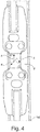
- the Figure 3 also shows a section of the lifting mast 1a in detail. This embodiment differs from that in FIG Figure 2 represented in that a sensor device 4 designed as a strain gauge 4 is attached to each of the mast profiles 1d.
- the sensor device 4 designed as a strain gauge 4 Figures 2 and 3rd presented in detail.
- the strain gauge 4 is integrated in the mast profile 1d in such a way that it is protected against mechanical damage.
- the elastic deformation of the mast profile 1d is measured by measuring strains and torsions in three-dimensional space. From this, tensile, compressive and torsional forces of mast profile 1d are determined as deformation data using Hook's law.
- the tensile and compressive forces are in the Figure 4 represented as force vectors which point in the three spatial directions x, y, z, the x direction corresponding to a vertical direction, the y direction corresponding to a vehicle transverse direction and the z direction corresponding to a vehicle longitudinal direction.
- the torsional forces are the radial forces around the force vectors shown as arrows. Thus, a total of six forces can be determined at this point with the strain gauge 4. If a strain gauge 4 is attached to each of the mast profiles 1d on two mast profiles 1d, a total of 12 forces can thus be determined. The forces are measured continuously with the strain gauges 4.
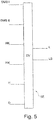
- the Figure 5 shows a diagram for the data processing DV in the control device of the industrial truck.
- the parameters determined by sensors are listed as well as the calculation model D as a calculation, physical stacker model.
- the data determined by the sensors include the forces DMS I and / or DMS II recorded by one or two strain gauges on one or both mast profiles (six forces per strain gauge in each case).
- the forces DMS I of a strain gauge are available, in a version according to Figure 3 the forces DMS I and DMS II of the two strain gauges are present.
- the tilting forces NK, the lifting forces HK of the lifting mast and the lifting height H can be available as parameters.
- the parameters DMS I and / or DMS II detected by the sensors and the parameters of If necessary, existing sensors register parameters NK, HK and H as well as comparison with the physical stacker model D, the load mass L and the center of gravity LS are calculated.
- the center of gravity is determined as a point in a three-dimensional coordinate system with the coordinates x, y and z, with the x coordinate the vertical center of gravity above the floor, the y coordinate the horizontal, lateral offset of the center of gravity to the center of the vehicle and the z coordinate represent the horizontal distance of the load center of gravity from the mast.
- the forces DMS I and / or DMS II detected by one or both strain gauges 4 would suffice for a comparison with the stacker model.
- the optional additional parameters NK, HK, H serve to further increase the measuring accuracy.
- FIG 6 shows a control structure to increase the tipping stability of the industrial truck, which is designed, for example, as a forklift. From the specifications P on the accelerator pedals, the steering wheel and the control levers originating from the driver of the industrial truck, a driving and loading state Z results, which is reported back to the driver in the form of a subjective perception W, whereupon the specifications P are changed if necessary.
- the forklift is equipped with sensors S, with the aid of which physical quantities can be detected, from which the driving and loading condition Z can be determined objectively.
- These variables include the load mass L and the load center LS, the lifting height H, the load moment M, the mast tilt angle WM, the steering angle WL turned on the steering axle, the direction of travel R, the driving speed V, the longitudinal acceleration BL, the lateral acceleration BQ and the yaw rate G.
- the load torque M for example, the tilting cylinder forces or the axle load of the steering axle (rear axle) can be used.
- the sensors S also include the strain gauges, which measure the elastic deformation of the mast profile by measuring strains and torsions in three-dimensional space. Using Hooke's law, tensile, compressive and torsional forces are determined as deformation data, which can be processed with the calculation model.
- sensors S mentioned A part of the sensors S mentioned is provided for the detection of physical quantities which are required for the determination of static and quasi-static risk of tipping. These are the sensors for detecting the direction of travel R, the driving speed V, the load mass L and the center of gravity LS, the lifting height H, the load torque M, the mast tilt angle WM and the steering angle WL turned on the steering axle. Additional physical quantities must be recorded in order to determine dynamic risk of tipping. For this purpose, sensors are provided for detecting the longitudinal acceleration BL, the transverse acceleration BQ and the yaw rate G.
- the measured values detected by the sensors S are passed on to the control device SE, in which, on the basis of vehicle-specific data, such as, for example, B. the dimensions and masses of the truck and the mast, the tire characteristics and the maximum possible load a computing model D of the forklift is stored.
- vehicle-specific data such as, for example, B. the dimensions and masses of the truck and the mast, the tire characteristics and the maximum possible load a computing model D of the forklift is stored.
- the current driving and loading condition Z of the industrial truck is determined in a driving status observer FB from the computing model D and the measured values of the sensors S and it is determined whether the work and / or driving movements are tilt-critical and therefore require interventions.
- Critical driving maneuvers FM1 and FM2 are monitored by the driving state observer FB for a first intervention area E1 and for a second intervention area E2.
- first intervention area E1 in which measures against static and / or quasi-static tipping are to be carried out, these are the driving maneuvers braking forward when the vehicle is tilted forward, accelerating backwards when the vehicle is tilted forward, braking from reversing in a curve when the vehicle is tilted perpendicular to Tilt axis and acceleration in forward travel in a curve with the vehicle inclined perpendicular to the tilt axis.
- FM2 can be used as a critical driving maneuver.
- the necessary interventions E in the traction drive, the steering drive and the working drive are derived, which lead to the tipping limits not being reached or exceeded.
- the control device SE thus increases the stability of the tilt.
- the interventions carried out are interventions in the intervention area E1 (e.g. reducing the driving and working speed) and interventions in the intervention area E2 (e.g. reducing the driving speed, changing the steering ratio to reduce the steering speed) with which the operator's specifications P are corrected (connection K1), for example by overriding the setpoints.
- it can involve interventions with which the specifications P are influenced at the moment of their creation (arrow K2), e.g. B an increase in the steering wheel torque required for turning the steering wheel in the second engagement area E2 or force feedback signals into the operating levers of the working hydraulics actuated by the driver, so that the driver is informed of the decreasing distances to system boundaries.
Abstract
Die Erfindung betrifft ein Verfahren zur Lastbestimmung bei einem Flurförderzeug, insbesondere einem Gegengewichtsgabelstapler oder Schubmaststapler, mit einer einen Hubmast (1a) mit mindestens einem Mastprofil (1d) umfassenden Lasthandhabungsvorrichtung (1), sowie ein entsprechendes Flurförderzeug. Es wird vorgeschlagen, dass eine elastische Verformung des Mastprofils (1d) mittels einer Sensorik (4) erfasst wird und daraus ermittelte Verformungsdaten mit einem in einer Steuereinrichtung (SE) des Flurförderzeugs gespeicherten, auf fahrzeugspezifischen Informationen basierenden, physikalischen Rechenmodell (D) des Flurförderzeugs verarbeitet werden, und daraus Lastmasse (L) und Lastschwerpunkt (LS) bestimmt werden.The invention relates to a method for determining the load in an industrial truck, in particular a counterbalance forklift or reach truck, with a load handling device (1) comprising a lifting mast (1a) with at least one mast profile (1d), and a corresponding industrial truck. It is proposed that an elastic deformation of the mast profile (1d) be detected by means of a sensor system (4) and process deformation data determined therefrom with a physical computing model (D) of the industrial truck that is stored in a control device (SE) of the industrial truck and is based on vehicle-specific information and the load mass (L) and load center of gravity (LS) are determined.
Description
Die Erfindung betrifft ein Verfahren zur Lastbestimmung bei einem Flurförderzeug, insbesondere einem Gegengewichtsgabelstapler oder Schubmaststapler, mit einer einen Hubmast mit mindestens einem Mastprofil umfassenden Lasthandhabungsvorrichtung, sowie ein entsprechendes Flurförderzeug.The invention relates to a method for determining the load in an industrial truck, in particular a counterbalance forklift or reach truck, with a load handling device comprising a lifting mast with at least one mast profile, and a corresponding industrial truck.
Zu den Flurförderzeugen gehören beispielsweise Gabelstapler, insbesondere Gegengewichtsgabelstapler, und Schubmaststapler. Derartige Flurförderzeuge sind mit einer Lasthandhabungsvorrichtung zum Stapeln und Einlagern von Transportgütern ausgestattet. Die Lasthandhabungsvorrichtung umfasst üblicherweise einen Hubmast mit mindestens einem Mastprofil. In der Regel sind zwei parallel zueinander angeordnete Mastprofile mit vertikaler Ausrichtung vorgesehen. Der Hubmast kann auch mit einer Neigeeinrichtung versehen sein, so dass die Mastprofile gegen die Vertikale neigbar sind. An den Mastprofilen kann ein Lastschlitten, insbesondere Gabelträger, an dem typischerweise Gabelzinken montiert sind, z.B. mittels einer Hubzylindereinrichtung einer Arbeitshydraulik vertikal verschoben werden. Auf den Gabelzinken kann eine Last beispielsweise über eine Palette aufgenommen werden.Industrial trucks include, for example, forklifts, especially counterbalanced forklifts, and reach trucks. Industrial trucks of this type are equipped with a load handling device for stacking and storing goods to be transported. The load handling device usually comprises a mast with at least one mast profile. As a rule, two mast profiles arranged parallel to each other with vertical alignment are provided. The mast can also be provided with a tilting device so that the mast profiles can be tilted against the vertical. A load carriage, in particular fork carriage, on which fork tines are typically mounted, e.g. be displaced vertically by means of a lifting cylinder device of a working hydraulic system. A load can be picked up on the forks using a pallet, for example.
Die Kenntnis des Lastgewichts ist für die Sicherheit von Flurförderzeugen, insbesondere im Hinblick auf die Standsicherheit, von großer Bedeutung. Dementsprechend ist eine Vielzahl von Vorrichtungen und Verfahren bekannt, um dieses Gewicht möglichst genau und mit wenig Aufwand zu bestimmen. Häufig wird versucht, im Flurförderzeug bereits vorhandene Vorrichtungen zur Lastmessung zu verwenden.Knowing the load weight is of great importance for the safety of industrial trucks, especially with regard to stability. Accordingly, a variety of devices and methods are known in order to determine this weight as accurately as possible and with little effort. An attempt is often made to use devices for load measurement that are already present in the industrial truck.
Eine Möglichkeit besteht dabei darin, aus dem zumeist ohnehin erfassten Druck in dem Teil des Hydraulikkreises der Arbeitshydraulik, der der Anhebung der Last dient, das Lastgewicht zu berechnen.One possibility is to calculate the load weight from the pressure, which is usually recorded anyway, in the part of the hydraulic circuit of the working hydraulics which serves to raise the load.
Bekannt sind beispielsweise kontinuierliche Lastmesssysteme, bei denen der Druck im Hubzylinder gemessen und daraus das Lastgewicht berechnet wird.Continuous load measuring systems are known, for example, in which the pressure in the lifting cylinder is measured and the load weight is calculated therefrom.
Andererseits existieren auch diskontinuierliche Lastmesssysteme, die im Moment des Senkstopps des Gabelträgers den Druckverlauf im Hubzylinder messen und daraus das Lastgewicht berechnen. Mit diesem Verfahren kann eine höhere Genauigkeit erzielt werden.On the other hand, there are also discontinuous load measuring systems that measure the pressure curve in the lifting cylinder at the moment the fork carriage stops lowering and calculate the load weight from this. With this method, a higher accuracy can be achieved.
Lastmesssysteme, die auf dem Prinzip der Druckmessung im Hydraulikkreis der Arbeitshydraulik beruhen, sind beispielsweise aus der
In der
Bezüglich der Bestimmung des Lastgewichts weisen die bekannten, in die Arbeitshydraulik integrierten, Systeme den Nachteil auf, dass interne Störeinflüsse der Hydraulik, z.B. Druckpulsationen und Slipstickeffekte, die nur in geschlossenen Hydrauliksystemen vorliegen, miterfasst werden. Dadurch kann die Lastbestimmung verfälscht werden.With regard to the determination of the load weight, the known systems integrated in the working hydraulics have the disadvantage that internal interference from the hydraulics, e.g. Pressure pulsations and slipstick effects, which are only present in closed hydraulic systems, are also recorded. This can falsify the load determination.
Eine andere Möglichkeit zur Lastmessung besteht darin, das Lastgewicht indirekt über eine Erfassung der Aufstandskraft des Flurförderzeugs an der Hinterachse zu ermitteln. Hierzu können Hinterachssensoren vorgesehen sein, die die elastische Verformung in der Hinterachse messen. Über die mittels des Hookschen Gesetzes ermittelte Aufstandskraft kann mit Hilfe einer Modellrechnung auf die Standsicherheit des Flurförderzeugs geschlossen werden, wobei eine große Aufstandskraft einer hohen Standsicherheit entspricht.Another possibility for load measurement is to determine the load weight indirectly by detecting the ground force of the industrial truck on the rear axle. For this purpose, rear axle sensors can be provided that measure the elastic deformation in the rear axle. A model calculation can be used to infer the stability of the industrial truck using the riot force determined using Hook's law, with a high riot force corresponding to a high level of stability.
Aus der
Bei der Lasthandhabung wird vom Fahrer eines Flurförderzeugs erwartet, dass er nicht nur die Lastmasse, sondern auch den Lastschwerpunkt einschätzen kann. Insbesondere bei Lasten, die nicht einsehbar sind, wie zum Beispiel in einem Regal, bei komplexen geometrischen Gebilden oder geschlossenen Transportkisten, ist dies dem Fahrer nicht möglich. Aufgrund von Fehleinschätzungen kann es zu Unfällen und Transportschäden kommen.When handling loads, the driver of an industrial truck is expected to be able to assess not only the load mass, but also the center of gravity. This is not possible for the driver, in particular with loads that cannot be seen, such as on a shelf, with complex geometric structures or closed transport boxes. Incorrect assessments can lead to accidents and damage in transit.
Die zitierten Druckschriften zum Stand der Technik bieten keine Lösung an, um auch den seitlichen Versatz des Lastschwerpunkts zur Fahrzeugmitte zu erfassen und bei der Bestimmung der Kippstabilität zu berücksichtigen.The cited prior art documents do not offer a solution to also detect the lateral offset of the load center of gravity to the center of the vehicle and to take this into account when determining the tipping stability.
Der vorliegenden Erfindung liegt die Aufgabe zugrunde, ein Verfahren der eingangs genannten Art sowie ein entsprechendes Flurförderzeug so auszugestalten, dass gleichzeitig Lastmasse und Lastschwerpunkt mit hoher Genauigkeit bestimmt werden können.The present invention is based on the object of designing a method of the type mentioned at the outset and a corresponding industrial truck in such a way that the load mass and center of gravity can be determined with high accuracy at the same time.
Diese Aufgabe wird verfahrensseitig erfindungsgemäß dadurch gelöst, dass eine elastische Verformung des Mastprofils mittels einer Sensorik erfasst wird und daraus ermittelte Verformungsdaten mit einem in einer Steuereinrichtung des Flurförderzeugs gespeicherten, auf fahrzeugspezifischen Informationen basierenden, physikalischen Rechenmodell des Flurförderzeugs verarbeitet werden, und daraus Lastmasse und Lastschwerpunkt bestimmt werden.In terms of the method, this object is achieved in accordance with the invention in that an elastic deformation of the mast profile is detected by means of a sensor system and deformation data determined therefrom are processed with a physical computing model of the industrial truck that is stored in a control device of the industrial truck and is based on vehicle-specific information, and determines the load mass and center of gravity from this become.
Der Erfindung liegt die Erkenntnis zu Grunde, dass durch Erfassung der elastischen Verformung des Mastprofils und Verarbeitung der Verformungsdaten mit einem fahrzeugspezifischen Rechenmodell, also im Fall eines Gegengewichtsgabelstaplers oder eines Schubmaststaplers mit einem rechnerischen Staplermodell, eine genaue Lastbestimmung ermöglicht wird. Auf diese Weise können Störeinflüsse, wie sei bei Messungen im Hydraulikkreis auftreten, verhindert werden.The invention is based on the knowledge that an accurate load determination is made possible by recording the elastic deformation of the mast profile and processing the deformation data with a vehicle-specific computing model, i.e. in the case of a counterbalance forklift or a reach truck with a mathematical forklift model. In this way, interferences, such as occur during measurements in the hydraulic circuit, can be prevented.
Bevorzugt basiert das Rechenmodell auf fahrzeugspezifischen Informationen zum lastabhängigen Verformungsverhalten des Mastprofils. Durch Vergleich der Modelldaten mit den gemessenen Verformungsdaten kann auf die Lastmasse und den Lastschwerpunkt geschlossen werden.The computing model is preferably based on vehicle-specific information on the load-dependent deformation behavior of the mast profile. By comparing the model data with the measured deformation data, conclusions can be drawn about the load mass and the center of gravity.
Eine weitere vorteilhafte Ausgestaltung sieht vor, dass das Rechenmodell auf fahrzeugspezifischen Informationen zum statischen und/oder quasistatischen und/oder dynamischen Kippverhalten des Flurförderzeugs basiert. Durch Verarbeitung der gemessenen Verformungsdaten mit den Modelldaten kann sowohl der Betriebszustand "statisches und/oder quasistatisches Kippen" (bei großer Hubhöhe und geringer Fahrgeschwindigkeit bzw. Stillstand) als auch der Betriebszustand "dynamisches Kippen" (hohe Querbeschleunigung bei Kurvenfahrt, hohe Längsbeschleunigung beim Bremsen) abgedeckt werden. Somit kann in das Fahrzeugverhalten des Flurförderzeugs so weit eingegriffen werden, dass ein Umkippen verhindert wird.A further advantageous embodiment provides that the computing model is based on vehicle-specific information on the static and / or quasi-static and / or dynamic tipping behavior of the industrial truck. By processing the measured deformation data with the model data, both the operating state "static and / or quasi-static tipping" (with high lifting height and low driving speed or standstill) and the operating state "dynamic tipping" (high lateral acceleration when cornering, high longitudinal acceleration when braking) can be covered. It is thus possible to intervene in the vehicle behavior of the industrial truck to such an extent that it does not tip over.
Zweckmäßigerweise wird die elastische Verformung des Mastprofils durch Messung von Dehnungen und Torsionen im dreidimensionalen Raum erfasst. Daraus werden beispielsweise mittels des Hookschen Gesetzes Zug-, Druck- und Torsionskräfte als Verformungsdaten ermittelt und mit entsprechenden Daten, die im Rechenmodell gespeichert sind, verglichen. Aus dem Abgleich mit dem Rechenmodell kann auf die Lastmasse und den Lastschwerpunkt geschlossen werden.The elastic deformation of the mast profile is expediently recorded by measuring expansions and torsions in three-dimensional space. From this, tensile, compressive and torsional forces, for example, are determined as deformation data by means of Hook's law and compared with corresponding data that are stored in the computing model. The load mass and the load center of gravity can be deduced from the comparison with the calculation model.
In einer besonders vorteilhaften Ausgestaltung der Erfindung wird die elastische Verformung des Mastprofils durch Messung von Dehnungen und Torsionen mittels mindestens eines Dehnungsmessstreifens erfasst. Die Verwendung von Dehnungsmessstreifen ist an sich eine bewährte Methode zur Spannungs- und Dehnungsmessung. Dehnungsmessstreifen kommen in den verschiedensten Anwendungsfällen zum Einsatz, um über die Dehnungsmessung indirekt Kräfte zu ermitteln. Ein Dehnungsmessstreifenmodul mit einem Dehnungsmessstreifen ist beispielsweise aus der
Dabei erfolgt die Messung bevorzugt kontinuierlich, so dass zu jedem Zeitpunkt die aktuelle Lastmasse und der aktuelle Lastschwerpunkt bestimmt werden können.The measurement is preferably carried out continuously, so that the current load mass and the current load center of gravity can be determined at any time.
Der Lastschwerpunkt wird vorteilhafterweise als Punkt in einem dreidimensionalen Koordinatensystem mit den Koordinaten x, y und z bestimmt, wobei die x-Koordinate die vertikale Lastschwerpunktshöhe über dem Fahrboden, die y-Koordinate den horizontalen, seitlichen Versatz des Lastschwerpunkts zur Fahrzeugmitte, d.h. zur Fahrzeuglängsmittelachse, und die z-Koordinate den horizontalen Abstand des Lastschwerpunkts vom Hubmast darstellen.The load center of gravity is advantageously determined as a point in a three-dimensional coordinate system with the coordinates x, y and z, the x coordinate being the vertical load center of gravity above the floor, the y coordinate the horizontal, lateral offset of the load center of gravity to the center of the vehicle, i.e. to the longitudinal axis of the vehicle, and the z coordinate represents the horizontal distance of the center of gravity from the mast.
Mit Hilfe einer Signalanalyse der üblicherweise digitalen Kraftsignale der mittels der Sensoreinrichtung erfassten Zug-, Druck- und Torsionskräfte mittels Fast-FourierTransformation (FFT) können die digitalen Kraftsignale in ihre Frequenzanteile zerlegt und diese dann analysiert werden. Auf diese Weise kann die Eigenfrequenz des Hubmastes bestimmt werden.With the aid of a signal analysis of the usually digital force signals of the tensile, compressive and torsional forces detected by means of the sensor device by means of Fast Fourier Transformation (FFT), the digital force signals can be broken down into their frequency components and these can then be analyzed. In this way, the natural frequency of the mast can be determined.
Aus statischen Auslenkungen bei der elastischen Verformung des Mastprofils kann mittels des Hebelgesetzes auf die Lastmasse geschlossen werden.The load mass can be deduced from the static deflections in the elastic deformation of the mast profile using the lever law.
Um die Messgenauigkeit weiter zu erhöhen, ist gemäß einer bevorzugten Weiterbildung des Erfindungsgedankens vorgesehen, dass mittels zusätzlicher Sensoren weitere Messwerte ermittelt werden, die ebenfalls in das Rechenmodell mit eingehen. Somit können Fehler gemeinsamer Ursachen ausgeschlossen werden.In order to further increase the measuring accuracy, it is provided according to a preferred development of the inventive concept that additional measured values are determined by means of additional sensors, which are also included in the computing model. Errors of common causes can thus be excluded.
Hierzu können insbesondere an der Lasthandhabungsvorrichtung wirkende Hubkräfte gemessen werden und die Hubkraft-Messwerte bei der Verarbeitung der Verformungsdaten mit dem Rechenmodell zusätzlich berücksichtigt werden.For this purpose, lifting forces acting in particular on the load handling device can be measured and the lifting force measured values can also be taken into account when processing the deformation data with the computing model.
Zusätzlich oder alternativ werden vorteilhafterweise an der Lasthandhabungsvorrichtung wirkende Neigekräfte gemessen und die Neigekraft-Messwerte bei der Verarbeitung der Verformungsdaten mit dem Rechenmodell zusätzlich berücksichtigt.Additionally or alternatively, tilt forces acting on the load handling device are advantageously measured and the tilt force measured values are additionally taken into account when processing the deformation data with the computing model.
In einer weiteren bevorzugten Ausgestaltung wird zusätzlich oder alternativ die Hubhöhe der Lasthandhabungsvorrichtung gemessen und die Hubhöhen-Messwerte bei der Verarbeitung der Verformungsdaten mit dem Rechenmodell zusätzlich berücksichtigt.In a further preferred embodiment, the lifting height of the load handling device is additionally or alternatively measured and the lifting height measured values are additionally taken into account when processing the deformation data using the computing model.
Zur Information des Fahrers des Flurförderzeugs über die Ergebnisse der Lastbestimmung ist zweckmäßigerweise vorgesehen, dass die Lastmasse und der Lastschwerpunkt in einer Anzeigevorrichtung für einen Fahrer angezeigt werden. Die Anzeigevorrichtung bildet somit die Schnittstelle zum Fahrer, um den Fahrer über Lastmasse und Position des Lastschwerpunktes in x-, y und z-Richtung der aufgenommenen Last in Kenntnis zu setzen.To inform the driver of the industrial truck about the results of the load determination, it is expediently provided that the load mass and the load center of gravity are displayed in a display device for a driver. The display device thus forms the interface to the driver in order to inform the driver of the load mass and the position of the center of gravity in the x, y and z directions of the picked up load.
In die Anzeigevorrichtung kann auch eine visuelle Warnung eingeblendet werden, um den Fahrer über den Abstand zu kritischen Systemgrenzen zu informieren. Der Fahrer kann dann geeignete Gegenmaßnahmen einleiten. Beispielsweise kann er die Fahrgeschwindigkeit des Flurförderzeugs reduzieren und/oder die Hubhöhe der Last verringern, um die volle Betriebssicherheit des Flurförderzeugs zu gewährleisten.A visual warning can also be shown in the display device in order to inform the driver of the distance to critical system boundaries. The driver can then take suitable countermeasures. For example, he can reduce the driving speed of the industrial truck and / or reduce the lifting height of the load in order to ensure the full operational safety of the industrial truck.
Zur Verringerung der Gefahr eines Kippens des Flurförderzeugs ist gemäß einer besonders vorteilhaften Ausführungsform der Erfindung vorgesehen, dass mit dem Rechenmodell ein Fahr- und Beladungszustand des Flurförderzeugs ermittelt wird, der auf physikalischen Größen beruht, die für ein statisches und/oder quasistatisches und/oder dynamisches Kippverhalten des Flurförderzeugs relevant sind.In order to reduce the risk of the industrial truck tipping over, it is provided according to a particularly advantageous embodiment of the invention that the computing model is used to determine a driving and loading condition of the industrial truck which is based on physical variables which are static and / or quasi-static and / or dynamic Tipping behavior of the industrial truck are relevant.
In einer einfachen Ausgestaltung wird der Fahr- und Beladungszustand des Flurförderzeugs in einer Anzeigevorrichtung für einen Fahrer angezeigt. Der Fahrer kann dann manuell entsprechende Maßnahmen einleiten, um ein Kippen des Flurförderzeugs zu verhindern.In a simple embodiment, the driving and loading status of the industrial truck is displayed in a display device for a driver. The driver can then manually take appropriate measures to prevent the truck from tipping over.
In einer weiterentwickelten Ausgestaltung ist eine Automatisierung vorgesehen, bei der die Steuereinrichtung selbständig abhängig vom ermittelten Fahr- und Beladungszustand des Flurförderzeugs kippstabilitätswahrende oder -erhöhende Korrektureingriffe in einen Fahrantrieb und/oder Lenkantrieb des Flurförderzeugs und/oder einen Arbeitsantrieb der Lasthandhabungsvorrichtung vornimmt.In a further developed embodiment, automation is provided, in which the control device independently carries out corrective interventions in a travel drive and / or steering drive of the industrial truck and / or a work drive of the load handling device depending on the determined driving and loading condition of the industrial truck.
Der Fahrer kann auch mittels automatisierter, abschaltender Eingriffe unterstützt werden, bei geringen Abständen zu Systemgrenzen diese nicht zu übersteuern. Diese Eingriffe können sowohl in die Arbeitshydrauliksteuerung als auch in die Fahrantriebssteuerung und in die Lenkungssteuerung reduzierend erfolgen. Ziel der Eingriffe ist insgesamt eine Reduzierung von kinetischer Energie sowie von großer kinetischer Energieänderung.The driver can also be supported by means of automated, switching-off interventions so that they are not overridden when the system limits are small. These interventions can be carried out in a reducing manner both in the working hydraulic control and in the travel drive control and in the steering control. goal of Interventions are overall a reduction of kinetic energy as well as a large kinetic energy change.
Die Erfindung betrifft ferner ein Flurförderzeug, insbesondere einen Gegengewichtsgabelstapler, mit einer einen Hubmast mit mindestens einem Mastprofil umfassenden Lasthandhabungsvorrichtung.The invention further relates to an industrial truck, in particular a counterbalance forklift, with a load handling device comprising a lifting mast with at least one mast profile.
Bei dem Flurförderzeug wird die gestellte Aufgabe dadurch gelöst, dass am Mastprofil mindestens eine Sensoreinrichtung angeordnet ist, welche zur Erfassung einer elastischen Verformung des Mastprofils und Ermittlung von Verformungsdaten ausgebildet ist, und die Sensoreinrichtung mit einer Steuereinrichtung des Flurförderzeugs in Wirkverbindung steht, in der ein auf fahrzeugspezifischen Informationen basierendes, physikalisches Rechenmodell des Flurförderzeugs gespeichert ist, und die Steuereinrichtung dazu eingerichtet ist, die von der Sensoreinrichtung ermittelten Verformungsdaten in dem Rechenmodell zu verarbeiten und daraus Lastmasse und Lastschwerpunkt zu bestimmen.In the industrial truck, the object is achieved in that at least one sensor device is arranged on the mast profile, which is designed to detect elastic deformation of the mast profile and determine deformation data, and the sensor device is operatively connected to a control device of the industrial truck, in which one vehicle-specific information-based physical computing model of the industrial truck is stored, and the control device is set up to process the deformation data determined by the sensor device in the computing model and to determine the load mass and center of gravity therefrom.
Zweckmäßigerweise umfasst die Sensoreinrichtung mindestens einen Dehnungsmessstreifen, der für eine Messung von Dehnungen und Torsionen im dreidimensionalen Raum ausgebildet ist.The sensor device expediently comprises at least one strain gauge, which is designed for measuring strains and torsions in three-dimensional space.
Dabei ist die Sensoreinrichtung bevorzugt so in das Mastprofil integriert, dass Unterschiede von Mastprofilen und Tonnagen in der mechanischen Integration berücksichtigt werden. Durch die Integration in das Mastprofil ist die Sensoreinrichtung außerdem gegen mechanische Beschädigungen geschützt.The sensor device is preferably integrated into the mast profile in such a way that differences in mast profiles and tonnages are taken into account in the mechanical integration. By integrating it into the mast profile, the sensor device is also protected against mechanical damage.
Ist die Lasthandhabungsvorrichtung des Flurförderzeugs so ausgebildet, dass der Hubmast zwei parallele Mastprofile umfasst, so ist vorzugsweise an jedem der beiden Mastprofile jeweils eine Sensoreinrichtung angeordnet.If the load handling device of the industrial truck is designed such that the lifting mast comprises two parallel mast profiles, a sensor device is preferably arranged on each of the two mast profiles.
Die Erfindung bietet eine ganze Reihe von Vorteilen:
Besonders vorteilhaft gegenüber dem Stand der Technik ist, dass erfindungsgemäß der Lastschwerpunkt dreidimensional in Bezug zum Fahrzeug erfasst werden kann.The invention offers a number of advantages:
It is particularly advantageous over the prior art that, according to the invention, the center of gravity of the load can be detected three-dimensionally in relation to the vehicle.
Insbesondere der seitliche Versatz zur Fahrzeugmitte wird bei den bisher verfügbaren Systemen nicht berücksichtigt.In particular, the lateral offset to the center of the vehicle is not taken into account in the systems available to date.
Von Vorteil ist außerdem die Skalierbarkeit der Sensortechnik. Erfindungsgemäß kann immer die gleiche Sensoreinrichtung in unterschiedlichen Fahrzeugen, Tonnagen und Mastsystemen verwendet werden. Dadurch wird der Einsatz von standardisierten Sensoreinrichtungen und eine kosteneffiziente Applizierung im Stahlbau ermöglicht.The scalability of the sensor technology is also an advantage. According to the invention, the same sensor device can always be used in different vehicles, tonnages and mast systems. This enables the use of standardized sensor devices and a cost-efficient application in steel construction.
Ein weiterer Vorteil besteht darin, dass das erfindungsgemäße System außerhalb der Hydraulikanlage misst. Interne Störpulse, Wellen oder unzulässige Arbeitspunkte, wie beispielsweise im Endanschlag der Arbeitshydraulik, werden nicht miterfasst. Aus diesem Grund muss mit der neuen Lösung keine komplexe Korrekturrechnung durchgeführt werden.Another advantage is that the system according to the invention measures outside the hydraulic system. Internal interference pulses, waves or impermissible working points, such as in the end stop of the working hydraulics, are not recorded. For this reason, the new solution does not require a complex correction calculation.
Die Erfindung ermöglicht es, die Vorteile unterschiedlicher Sensortechnologien miteinander zu verknüpfen. Auf diese Weise entstehen genauere Messwerte, die zugleich robuster in den unterschiedlichen Arbeitspunkten des Flurförderzeugs sind. Darüber hinaus können auf diese Weise elegant Fehler gemeinsamer Ursache ausgeschlossen werden.The invention makes it possible to combine the advantages of different sensor technologies with one another. In this way, more precise measured values are created, which are also more robust in the different operating points of the industrial truck. In addition, errors of common cause can be elegantly excluded in this way.
Mittels der Schnittstelle zum Flurförderzeug kann der Fahrer beim Lasthandling informiert und unterstützt werden. Insbesondere bei Lasten, die nicht einsehbar sind, wie zum Beispiel im Regal, bei komplexen geometrischen Gebilden oder geschlossenen Transportkisten, wird der Fahrer gezielt informiert und unterstützt. Durch die Information des Fahrers über das Lastgewicht und der Position des Lastschwerpunktes in x-, y und z-Richtung kann der Fahrer Unfälle und Transportschäden vermeiden.The driver can be informed and supported during load handling using the interface to the industrial truck. The driver is specifically informed and supported in the case of loads that cannot be seen, such as on the shelf, with complex geometric structures or closed transport boxes. By informing the driver of the load weight and the position of the center of gravity in the x, y and z directions, the driver can avoid accidents and transport damage.
Mittels automatisierter Eingriffe durch die Steuerungseinrichtung können kritische Situationen aktiv verhindert werden.Critical situations can be actively prevented by means of automated interventions by the control device.
Weitere Vorteile und Einzelheiten der Erfindung werden anhand der in den schematischen Figuren dargestellten Ausführungsbeispiele näher erläutert. Hierbei zeigen
Figur 1- eine perspektivische Darstellung eines Flurförderzeugs,
Figur 2- eine Detaildarstellung eines Hubmastes mit einer Sensoreinrichtung,
Figur 3- eine Detaildarstellung eines Hubmastes mit zwei Sensoreinrichtungen,
Figur 4- eine Detaildarstellung der Sensoreinrichtung,
- Figur 5
- ein Schema für die Datenverarbeitung in der Steuereinrichtung und
- Figur 6
- ein Schema einer Regelstruktur zur Erhöhung der Kippstabilität des Flurförderzeugs.
- Figure 1
- a perspective view of an industrial truck,
- Figure 2
- a detailed representation of a mast with a sensor device,
- Figure 3
- a detailed representation of a mast with two sensor devices,
- Figure 4
- a detailed representation of the sensor device,
- Figure 5
- a scheme for data processing in the control device and
- Figure 6
- a diagram of a control structure to increase the tipping stability of the truck.
Das Flurförderzeug gemäß der
Der Hubmast 1a ist um eine im unteren Bereich quer angeordnete Horizontalachse neigbar. Selbstverständlich ist es auch möglich, einen starren, also nicht neigbaren Hubmast 1a vorzusehen und stattdessen den Lastschlitten 1b nicht nur höhenbeweglich, sondern auch neigbar auszuführen, wie dies zum Beispiel bei sogenannten Lagertechnik-Geräten (z. B. Schubmaststapler) häufig der Fall ist. An dem Lastschlitten 1b können - je nach Einsatzfall - auch andere Lastaufnahmeeinrichtungen befestigt werden. Es versteht sich, dass grundsätzlich auch zusätzliche Bewegungen der Lasthandhabungsvorrichtung 1 möglich sind, sofern die dazu erforderlichen Einrichtungen, z. B. ein Seitenschieber, zur Verfügung stehen.The
Der Hubmast 1a ist mittels hydraulischer Neigezylinder 1e neigbar. Das Ausfahren des Hubmastes 1a und das Anheben des Lastschlittens 1b erfolgt mittels hydraulischer Hubzylinder, ggf. zusätzlich mit einer oder mehreren Lastketten. Zum Absenken des Lastschlittens 1b bzw. Einfahren des Hubmastes 1a wirken das Eigengewicht des Lastschlittens 1b und der nach oben ausgefahren Komponenten des Hubmastes 1a sowie ggf. das Gewicht des Ladeguts. Die genannten hydraulischen Verbraucher werden von einer hydraulischen Pumpe gespeist. Zusammen mit den erforderlichen hydraulischen Ventilen und einem die Pumpe antreibenden Motor umfasst dieses System also mehrere Arbeitsantriebe für die Hub-, Senk- und Neigebewegung der Lasthandhabungsvorrichtung 1.The
Das Flurförderzeug gemäß dem Ausführungsbeispiel weist ferner einen Fahrantrieb auf, bei dem eine Vorderachse 2 als Antriebsachse ausgebildet ist, und einen Lenkantrieb, mit dessen Hilfe eine heckseitig angeordnete Lenkachse 3 betätigt wird.The industrial truck according to the exemplary embodiment also has a travel drive, in which a
An einem Mastprofil 1d oder an beiden Mastprofilen 1d ist jeweils eine als Dehnungsmessstreifen 4 ausgebildete Sensoreinrichtung 4 angebracht. Mittels des Dehnungsmessstreifens 4 wird die elastische Verformung des entsprechenden Mastprofile 1d durch Messung von Dehnungen und Torsionen im dreidimensionalen Raum erfasst. Daraus werden mittels des Hookschen Gesetzes Zug-, Druck- und Torsionskräfte im Mastprofil 1d als Verformungsdaten ermittelt. Die Verformungsdaten werden über eine Datenleitung oder drahtlos über eine Funkverbindung an eine Steuereinrichtung SE des Flurförderzeugs übermittelt. In der Steuereinrichtung ist ein physikalisches Rechenmodell des Flurförderzeugs gespeichert, das auf fahrzeugspezifischen Informationen beruht. Zu diesen fahrzeugspezifischen Informationen gehören Parameter, die die Kippstabilität des Flurförderzeugs beeinflussen, wie die Abmessungen und Massen des Flurförderzeugs und des Hubmastes 1a, die Reifencharakteristika und die maximal mögliche Zuladung. Außerdem enthält das Rechenmodell auch Daten zum lastabhängigen Verformungsverhalten der Mastprofile. Insgesamt stellt das Rechenmodell ein umfassendes rechnerisches Modell des Flurförderzeugs, also ein elektronisches Staplermodell, dar. In der Steuereinrichtung SE werden die von den Dehnungsmessstreifen 4 erfassten Verformungsdaten mit dem Rechenmodell verarbeitet, so dass auf die Lastmasse und den Lastschwerpunkt einer auf den Gabelzinken 1c befindlichen Last geschlossen werden.A
In der
Die
In der
Die
An sich würden die von einem oder beiden Dehnungsmessstreifen 4 erfassten Kräfte DMS I und/oder DMS II für einen Abgleich mit dem Staplermodell genügen. Die optionalen zusätzlichen Parameter NK, HK, H dienen der weiteren Erhöhung der Messgenauigkeit.As such, the forces DMS I and / or DMS II detected by one or both
In der
Der Gabelstapler ist mit Sensoren S ausgestattet, mit deren Hilfe physikalische Größen erfassbar sind, aus denen sich der Fahr- und Beladungszustand Z objektiv ermitteln lässt. Zu diesen Größen zählen die Lastmasse L und der Lastschwerpunkt LS, die Hubhöhe H, das Lastmoment M, der Mast-Neigewinkel WM, der an der Lenkachse eingeschlagene Lenkwinkel WL, die Fahrtrichtung R, die Fahrgeschwindigkeit V, die Längsbeschleunigung BL, die Querbeschleunigung BQ und die Gierrate G. Zur Bestimmung des Lastmoments M können beispielsweise die Neigezylinderkräfte oder die Achslast der Lenkachse (Hinterachse) herangezogen werden.The forklift is equipped with sensors S, with the aid of which physical quantities can be detected, from which the driving and loading condition Z can be determined objectively. These variables include the load mass L and the load center LS, the lifting height H, the load moment M, the mast tilt angle WM, the steering angle WL turned on the steering axle, the direction of travel R, the driving speed V, the longitudinal acceleration BL, the lateral acceleration BQ and the yaw rate G. To determine the load torque M, for example, the tilting cylinder forces or the axle load of the steering axle (rear axle) can be used.
Zu den Sensoren S gehören auch die Dehnungsmessstreifen, die die elastische Verformung des Mastprofils durch Messung von Dehnungen und Torsionen im dreidimensionalen Raum erfassen. Daraus werden mittels des Hookschen Gesetzes Zug-, Druck- und Torsionskräfte als Verformungsdaten ermittelt, die mit dem Rechenmodell verarbeitet werden können.The sensors S also include the strain gauges, which measure the elastic deformation of the mast profile by measuring strains and torsions in three-dimensional space. Using Hooke's law, tensile, compressive and torsional forces are determined as deformation data, which can be processed with the calculation model.
Von den genannten Sensoren S ist ein Teil für die Erfassung physikalischer Größen vorgesehen, die für die Ermittlung von statischen und quasistatischen Kippgefährdungen erforderlich sind. Es handelt sich dabei um die Sensoren zur Erfassung der Fahrtrichtung R, der Fahrgeschwindigkeit V, der Lastmasse L sowie des Lastschwerpunkts LS, der Hubhöhe H, des Lastmoments M, des Mast-Neigewinkel WM und des an der Lenkachse eingeschlagenen Lenkwinkels WL. Für die Ermittlung von dynamischen Kippgefährdungen müssen zusätzliche physikalische Größen erfasst werden. Zu diesem Zweck sind Sensoren zur Erfassung der Längsbeschleunigung BL, der Querbeschleunigung BQ und der Gierrate G vorgesehen.A part of the sensors S mentioned is provided for the detection of physical quantities which are required for the determination of static and quasi-static risk of tipping. These are the sensors for detecting the direction of travel R, the driving speed V, the load mass L and the center of gravity LS, the lifting height H, the load torque M, the mast tilt angle WM and the steering angle WL turned on the steering axle. Additional physical quantities must be recorded in order to determine dynamic risk of tipping. For this purpose, sensors are provided for detecting the longitudinal acceleration BL, the transverse acceleration BQ and the yaw rate G.
Die von den Sensoren S erfassten Messwerte werden an die Steuereinrichtung SE weitergegeben, in der anhand von fahrzeugspezifischen Daten, wie z. B. den Abmessungen und Massen des Flurförderzeugs und des Hubmastes, den Reifencharakteristika und der maximal möglichen Zuladung ein Rechenmodell D des Gabelstaplers abgelegt ist.The measured values detected by the sensors S are passed on to the control device SE, in which, on the basis of vehicle-specific data, such as, for example, B. the dimensions and masses of the truck and the mast, the tire characteristics and the maximum possible load a computing model D of the forklift is stored.
In der Steuereinrichtung SE wird in einem Fahrzustandsbeobachter FB aus dem Rechenmodell D und den Messwerten der Sensoren S der aktuelle Fahr- und Beladungszustand Z des Flurförderzeugs ermittelt und dabei festgestellt, ob die Arbeits- und/oder Fahrbewegungen kippkritisch sind und deshalb Eingriffe erforderlich machen.In the control device SE, the current driving and loading condition Z of the industrial truck is determined in a driving status observer FB from the computing model D and the measured values of the sensors S and it is determined whether the work and / or driving movements are tilt-critical and therefore require interventions.
Hierbei werden vom Fahrzustandsbeobachter FB für einen ersten Eingriffsbereich E1 und für einen zweiten Eingriffsbereich E2 kritische Fahrmanöver FM1 bzw. FM2 überwacht. Für den ersten Eingriffsbereich E1, in dem ggf. Maßnahmen gegen statisches und/oder quasistatisches Kippen erfolgen sollen, sind dies die Fahrmanöver Bremsen vorwärts bei Fahrzeugschrägstellung nach vorn, Beschleunigen rückwärts bei Fahrzeugschrägstellung nach vorn, Bremsen aus der Rückwärtsfahrt in einer Kurve bei Fahrzeugschrägstellung senkrecht zur Kippachse und Beschleunigen in die Vorwärtsfahrt in einer Kurve bei Fahrzeugschrägstellung senkrecht zur Kippachse.Critical driving maneuvers FM1 and FM2 are monitored by the driving state observer FB for a first intervention area E1 and for a second intervention area E2. For the first intervention area E1, in which measures against static and / or quasi-static tipping are to be carried out, these are the driving maneuvers braking forward when the vehicle is tilted forward, accelerating backwards when the vehicle is tilted forward, braking from reversing in a curve when the vehicle is tilted perpendicular to Tilt axis and acceleration in forward travel in a curve with the vehicle inclined perpendicular to the tilt axis.
Für den zweiten Eingriffsbereich E2, in dem Maßnahmen gegen dynamisches Kippen erfolgen sollen, kann als kritisches Fahrmanöver FM2 z. B. die Lenkgeschwindigkeit überwacht werden. Daraus können nun die gegebenenfalls erforderlichen Eingriffe E in den Fahrantrieb, den Lenkantrieb und Arbeitsantrieb abgeleitet werden, die dazu führen, dass die Kippgrenzen nicht erreicht bzw. überschritten werden. Die Steuereinrichtung SE wirkt somit kippstabilitätserhöhend.For the second intervention area E2, in which measures are to be taken against dynamic tipping, FM2 can be used as a critical driving maneuver. B. the steering speed can be monitored. The necessary interventions E in the traction drive, the steering drive and the working drive are derived, which lead to the tipping limits not being reached or exceeded. The control device SE thus increases the stability of the tilt.
Bei den durchgeführten Eingriffen handelt es sich um Eingriffe im Eingriffsbereich E1, (z. B. Reduzierung der Fahr- und Arbeitsgeschwindigkeit) und um Eingriffe im Eingriffsbereich E2 (z. B. Reduzierung der Fahrgeschwindigkeit, Änderung der Lenkübersetzung zwecks Reduzierung der Lenkgeschwindigkeit), mit denen jeweils die Vorgaben P der Bedienperson korrigiert werden (Verbindung K1), beispielsweise durch Übersteuerung der Sollwerte. Darüber hinaus kann es sich um Eingriffe handeln, mit denen die Vorgaben P im Moment ihrer Entstehung beeinflusst werden (Pfeil K2), z. B eine Erhöhung des zum Drehen des Lenkrades erforderlichen Lenkradmoments im zweiten Eingriffsbereich E2 oder Forcefeedbacksignalen in die vom Fahrer betätigten Bedienhebel der Arbeitshydraulik, so dass der Fahrer über geringer werdende Abstände zu systemgrenzen informiert wird.The interventions carried out are interventions in the intervention area E1 (e.g. reducing the driving and working speed) and interventions in the intervention area E2 (e.g. reducing the driving speed, changing the steering ratio to reduce the steering speed) with which the operator's specifications P are corrected (connection K1), for example by overriding the setpoints. In addition, it can involve interventions with which the specifications P are influenced at the moment of their creation (arrow K2), e.g. B an increase in the steering wheel torque required for turning the steering wheel in the second engagement area E2 or force feedback signals into the operating levers of the working hydraulics actuated by the driver, so that the driver is informed of the decreasing distances to system boundaries.
Claims (16)
Applications Claiming Priority (1)
| Application Number | Priority Date | Filing Date | Title |
|---|---|---|---|
| DE102018133095.2A DE102018133095A1 (en) | 2018-12-20 | 2018-12-20 | Method for determining the load on an industrial truck and industrial truck |
Publications (1)
| Publication Number | Publication Date |
|---|---|
| EP3670428A1 true EP3670428A1 (en) | 2020-06-24 |
Family
ID=69063584
Family Applications (1)
| Application Number | Title | Priority Date | Filing Date |
|---|---|---|---|
| EP19212029.3A Pending EP3670428A1 (en) | 2018-12-20 | 2019-11-28 | Industrial truck and method for determining load in an industrial truck |
Country Status (2)
| Country | Link |
|---|---|
| EP (1) | EP3670428A1 (en) |
| DE (1) | DE102018133095A1 (en) |
Cited By (1)
| Publication number | Priority date | Publication date | Assignee | Title |
|---|---|---|---|---|
| EP3978420A1 (en) * | 2020-09-30 | 2022-04-06 | STILL GmbH | Method for damping mast torsional vibration in an industrial truck and industrial truck |
Citations (9)
| Publication number | Priority date | Publication date | Assignee | Title |
|---|---|---|---|---|
| DE102005012004A1 (en) | 2004-04-07 | 2005-10-27 | Linde Ag | Counterbalanced forklift truck, has control device cooperating with rolling drive, working drive and steering lock drive such that device executes correction intervention maintaining or increasing stability against tilting of truck |
| DE102005011998A1 (en) | 2004-04-07 | 2005-10-27 | Linde Ag | Industrial truck e.g. fork-lift truck determines driving and load state based on detected variables and stored calculation model and accordingly reduces operating speed, starting/braking acceleration and driving speed |
| DE102008035574A1 (en) * | 2008-07-30 | 2010-02-04 | Linde Material Handling Gmbh | Load center determining method for load at load-carrying equipment of e.g. reach truck, involves detecting pressure of lift drive as reference value for determination of balance point distance of load in unloaded condition |
| EP2172413A1 (en) * | 2008-10-01 | 2010-04-07 | Linde Material Handling GmbH | Method for displaying allowable loads |
| DE102011118984A1 (en) * | 2011-11-19 | 2013-05-23 | Jungheinrich Aktiengesellschaft | Industrial truck for transportation of loads, has evaluation- and transmission unit that determines load and/or load center distance accommodated by fork and transmits evaluated data to central controller |
| DE202012002445U1 (en) * | 2012-03-06 | 2013-06-07 | Jungheinrich Aktiengesellschaft | Truck with optionally selectable destacking auxiliary mode |
| EP1953114B1 (en) | 2007-02-01 | 2013-07-17 | STILL GmbH | Industrial truck with a hydraulically liftable load pick-up |
| DE102014117334A1 (en) | 2014-11-26 | 2016-06-02 | Still Gmbh | Strain gauge module, assembly process on a mobile work machine and mobile work machine |
| DE102015104069A1 (en) | 2015-03-18 | 2016-09-22 | Still Gmbh | Method for determining the tipping stability of a truck |
-
2018
- 2018-12-20 DE DE102018133095.2A patent/DE102018133095A1/en active Pending
-
2019
- 2019-11-28 EP EP19212029.3A patent/EP3670428A1/en active Pending
Patent Citations (9)
| Publication number | Priority date | Publication date | Assignee | Title |
|---|---|---|---|---|
| DE102005012004A1 (en) | 2004-04-07 | 2005-10-27 | Linde Ag | Counterbalanced forklift truck, has control device cooperating with rolling drive, working drive and steering lock drive such that device executes correction intervention maintaining or increasing stability against tilting of truck |
| DE102005011998A1 (en) | 2004-04-07 | 2005-10-27 | Linde Ag | Industrial truck e.g. fork-lift truck determines driving and load state based on detected variables and stored calculation model and accordingly reduces operating speed, starting/braking acceleration and driving speed |
| EP1953114B1 (en) | 2007-02-01 | 2013-07-17 | STILL GmbH | Industrial truck with a hydraulically liftable load pick-up |
| DE102008035574A1 (en) * | 2008-07-30 | 2010-02-04 | Linde Material Handling Gmbh | Load center determining method for load at load-carrying equipment of e.g. reach truck, involves detecting pressure of lift drive as reference value for determination of balance point distance of load in unloaded condition |
| EP2172413A1 (en) * | 2008-10-01 | 2010-04-07 | Linde Material Handling GmbH | Method for displaying allowable loads |
| DE102011118984A1 (en) * | 2011-11-19 | 2013-05-23 | Jungheinrich Aktiengesellschaft | Industrial truck for transportation of loads, has evaluation- and transmission unit that determines load and/or load center distance accommodated by fork and transmits evaluated data to central controller |
| DE202012002445U1 (en) * | 2012-03-06 | 2013-06-07 | Jungheinrich Aktiengesellschaft | Truck with optionally selectable destacking auxiliary mode |
| DE102014117334A1 (en) | 2014-11-26 | 2016-06-02 | Still Gmbh | Strain gauge module, assembly process on a mobile work machine and mobile work machine |
| DE102015104069A1 (en) | 2015-03-18 | 2016-09-22 | Still Gmbh | Method for determining the tipping stability of a truck |
Cited By (1)
| Publication number | Priority date | Publication date | Assignee | Title |
|---|---|---|---|---|
| EP3978420A1 (en) * | 2020-09-30 | 2022-04-06 | STILL GmbH | Method for damping mast torsional vibration in an industrial truck and industrial truck |
Also Published As
| Publication number | Publication date |
|---|---|
| DE102018133095A1 (en) | 2020-06-25 |
Similar Documents
| Publication | Publication Date | Title |
|---|---|---|
| DE102005012004B4 (en) | Industrial truck with increased static / quasi-static and dynamic tipping stability | |
| EP0483493B1 (en) | Fork lift truck with load condition monitoring device | |
| EP2172413B2 (en) | Method for displaying allowable loads | |
| EP2982944B1 (en) | Vehicle wheel speed based monitoring and/or estimation of a load weight of an industrial vehicle load | |
| EP2580152B1 (en) | Method for determining the probability of a handling truck's tipping over | |
| DE102012109530A1 (en) | Method for center of gravity determination in industrial truck, involves detecting load applied on load receiving unit by image processing method through evaluation computer from camera image, such as pattern- or object recognition | |
| DE102017011302A1 (en) | FORKLIFT | |
| EP1953114B1 (en) | Industrial truck with a hydraulically liftable load pick-up | |
| DE102005011998B4 (en) | Industrial truck with increased static or quasi-static tipping stability | |
| EP1757739A2 (en) | Overload warning device for excavators | |
| DE102008035574A1 (en) | Load center determining method for load at load-carrying equipment of e.g. reach truck, involves detecting pressure of lift drive as reference value for determination of balance point distance of load in unloaded condition | |
| DE202008005966U1 (en) | Truck with distance sensor for wheelchair force determination | |
| EP3670428A1 (en) | Industrial truck and method for determining load in an industrial truck | |
| DE102011118984A1 (en) | Industrial truck for transportation of loads, has evaluation- and transmission unit that determines load and/or load center distance accommodated by fork and transmits evaluated data to central controller | |
| EP3546414B1 (en) | Method for determining the weight of a load held by a loading machine and loading machine for same | |
| DE202013101202U1 (en) | Stability control device and commercial vehicle | |
| DE10226599A1 (en) | Method for controlling at least one movement of an industrial truck | |
| DE102019121497A1 (en) | Industrial truck and method for monitoring an industrial truck | |
| EP2450305B1 (en) | Industrial truck with deformation sensor in tilt cylinder | |
| DE102017127258A1 (en) | Method for determining the center of gravity of an industrial truck and industrial truck for carrying out the method | |
| WO2022218743A1 (en) | Method for monitoring the state of a pallet truck of a stacker vehicle | |
| EP3070046A1 (en) | Method for determining the tilt stability of an industrial truck | |
| DE102012010248A1 (en) | Load handling vehicle e.g. reach stacker has load receiving unit fixed with hydraulically-adjustable load-bearing arm by joint, and weighing device that is arranged in hinge for determining weight distribution of suspended load | |
| EP1371604A2 (en) | Lifting device for an industrial truck | |
| DE102018118018A1 (en) | Method for operating an industrial truck with monitoring of the load condition and corresponding truck |
Legal Events
| Date | Code | Title | Description |
|---|---|---|---|
| PUAI | Public reference made under article 153(3) epc to a published international application that has entered the european phase |
Free format text: ORIGINAL CODE: 0009012 |
|
| STAA | Information on the status of an ep patent application or granted ep patent |
Free format text: STATUS: THE APPLICATION HAS BEEN PUBLISHED |
|
| AK | Designated contracting states |
Kind code of ref document: A1 Designated state(s): AL AT BE BG CH CY CZ DE DK EE ES FI FR GB GR HR HU IE IS IT LI LT LU LV MC MK MT NL NO PL PT RO RS SE SI SK SM TR |
|
| AX | Request for extension of the european patent |
Extension state: BA ME |
|
| STAA | Information on the status of an ep patent application or granted ep patent |
Free format text: STATUS: REQUEST FOR EXAMINATION WAS MADE |
|
| 17P | Request for examination filed |
Effective date: 20201221 |
|
| RBV | Designated contracting states (corrected) |
Designated state(s): AL AT BE BG CH CY CZ DE DK EE ES FI FR GB GR HR HU IE IS IT LI LT LU LV MC MK MT NL NO PL PT RO RS SE SI SK SM TR |
|
| STAA | Information on the status of an ep patent application or granted ep patent |
Free format text: STATUS: EXAMINATION IS IN PROGRESS |
|
| 17Q | First examination report despatched |
Effective date: 20220831 |