EP3670394A1 - Appareil à percussion de mise en mouvement d'un résidu de granulat en fond de cuve d'un élévateur à godets, et élévateur à godets de convoyage d'un granulat équipé d'un tel appareil - Google Patents
Appareil à percussion de mise en mouvement d'un résidu de granulat en fond de cuve d'un élévateur à godets, et élévateur à godets de convoyage d'un granulat équipé d'un tel appareil Download PDFInfo
- Publication number
- EP3670394A1 EP3670394A1 EP19201131.0A EP19201131A EP3670394A1 EP 3670394 A1 EP3670394 A1 EP 3670394A1 EP 19201131 A EP19201131 A EP 19201131A EP 3670394 A1 EP3670394 A1 EP 3670394A1
- Authority
- EP
- European Patent Office
- Prior art keywords
- tank
- striker
- bottom wall
- buckets
- column
- Prior art date
- Legal status (The legal status is an assumption and is not a legal conclusion. Google has not performed a legal analysis and makes no representation as to the accuracy of the status listed.)
- Granted
Links
Images


Classifications
-
- B—PERFORMING OPERATIONS; TRANSPORTING
- B65—CONVEYING; PACKING; STORING; HANDLING THIN OR FILAMENTARY MATERIAL
- B65G—TRANSPORT OR STORAGE DEVICES, e.g. CONVEYORS FOR LOADING OR TIPPING, SHOP CONVEYOR SYSTEMS OR PNEUMATIC TUBE CONVEYORS
- B65G65/00—Loading or unloading
- B65G65/02—Loading or unloading machines comprising essentially a conveyor for moving the loads associated with a device for picking-up the loads
- B65G65/06—Loading or unloading machines comprising essentially a conveyor for moving the loads associated with a device for picking-up the loads with endless scraping or elevating pick-up conveyors
-
- B—PERFORMING OPERATIONS; TRANSPORTING
- B65—CONVEYING; PACKING; STORING; HANDLING THIN OR FILAMENTARY MATERIAL
- B65G—TRANSPORT OR STORAGE DEVICES, e.g. CONVEYORS FOR LOADING OR TIPPING, SHOP CONVEYOR SYSTEMS OR PNEUMATIC TUBE CONVEYORS
- B65G17/00—Conveyors having an endless traction element, e.g. a chain, transmitting movement to a continuous or substantially-continuous load-carrying surface or to a series of individual load-carriers; Endless-chain conveyors in which the chains form the load-carrying surface
- B65G17/12—Conveyors having an endless traction element, e.g. a chain, transmitting movement to a continuous or substantially-continuous load-carrying surface or to a series of individual load-carriers; Endless-chain conveyors in which the chains form the load-carrying surface comprising a series of individual load-carriers fixed, or normally fixed, relative to traction element
- B65G17/126—Bucket elevators
-
- B—PERFORMING OPERATIONS; TRANSPORTING
- B65—CONVEYING; PACKING; STORING; HANDLING THIN OR FILAMENTARY MATERIAL
- B65G—TRANSPORT OR STORAGE DEVICES, e.g. CONVEYORS FOR LOADING OR TIPPING, SHOP CONVEYOR SYSTEMS OR PNEUMATIC TUBE CONVEYORS
- B65G65/00—Loading or unloading
- B65G65/30—Methods or devices for filling or emptying bunkers, hoppers, tanks, or like containers, of interest apart from their use in particular chemical or physical processes or their application in particular machines, e.g. not covered by a single other subclass
- B65G65/32—Filling devices
-
- B—PERFORMING OPERATIONS; TRANSPORTING
- B65—CONVEYING; PACKING; STORING; HANDLING THIN OR FILAMENTARY MATERIAL
- B65G—TRANSPORT OR STORAGE DEVICES, e.g. CONVEYORS FOR LOADING OR TIPPING, SHOP CONVEYOR SYSTEMS OR PNEUMATIC TUBE CONVEYORS
- B65G65/00—Loading or unloading
- B65G65/30—Methods or devices for filling or emptying bunkers, hoppers, tanks, or like containers, of interest apart from their use in particular chemical or physical processes or their application in particular machines, e.g. not covered by a single other subclass
- B65G65/34—Emptying devices
- B65G65/40—Devices for emptying otherwise than from the top
- B65G65/46—Devices for emptying otherwise than from the top using screw conveyors
- B65G65/463—Devices for emptying otherwise than from the top using screw conveyors arranged vertically or substantially vertically within the container
-
- B—PERFORMING OPERATIONS; TRANSPORTING
- B65—CONVEYING; PACKING; STORING; HANDLING THIN OR FILAMENTARY MATERIAL
- B65G—TRANSPORT OR STORAGE DEVICES, e.g. CONVEYORS FOR LOADING OR TIPPING, SHOP CONVEYOR SYSTEMS OR PNEUMATIC TUBE CONVEYORS
- B65G2201/00—Indexing codes relating to handling devices, e.g. conveyors, characterised by the type of product or load being conveyed or handled
- B65G2201/04—Bulk
- B65G2201/042—Granular material
-
- B—PERFORMING OPERATIONS; TRANSPORTING
- B65—CONVEYING; PACKING; STORING; HANDLING THIN OR FILAMENTARY MATERIAL
- B65G—TRANSPORT OR STORAGE DEVICES, e.g. CONVEYORS FOR LOADING OR TIPPING, SHOP CONVEYOR SYSTEMS OR PNEUMATIC TUBE CONVEYORS
- B65G47/00—Article or material-handling devices associated with conveyors; Methods employing such devices
- B65G47/52—Devices for transferring articles or materials between conveyors i.e. discharging or feeding devices
- B65G47/56—Devices for transferring articles or materials between conveyors i.e. discharging or feeding devices to or from inclined or vertical conveyor sections
- B65G47/58—Devices for transferring articles or materials between conveyors i.e. discharging or feeding devices to or from inclined or vertical conveyor sections for materials in bulk
Definitions
- the invention relates to the field of aggregate packet conveyors.
- the invention relates more particularly to elevators with conveying buckets in bulk and in packages of an aggregate, in particular cereal.
- the invention relates more specifically to the methods of setting in motion and collection by the buckets, of an aggregate residue at the bottom of a tank for collecting the aggregate to be conveyed that comprises such a bucket elevator.
- a bucket elevator In the field of agricultural equipment, it is common to use a bucket elevator to supply a silo, in bulk and in packages, of cereal grains or by analogy of cereal flour.
- the elevator is arranged in a column which extends vertically in elevation from the ground and which houses a bucket conveyor.
- the base of the column is arranged in an intake tank from outside the elevator for the grain to be conveyed, and the top of the column is arranged as a weir outside the elevator towards the silo for the conveyed grain.
- the conveyor extends in elevation inside the column between the tank and the weir, and includes buckets distributed along a strap closed in loop on itself.
- the buckets are driven by the strap between the tank and the weir, preferably circulating inside conduits formed inside the column.
- the strap is kept in tension between its ends around guide drums and / or strap drive, which are mounted rotating on the column.
- a lower drum is placed inside the tank to allow the buckets to draw the aggregate inside the tank, and an upper drum is placed inside the weir towards which the buckets are emptied before their return towards the tank.
- the motorized rotation of at least one of the drums provides a drive for the strap closed in a loop on itself, which circulates on the periphery of the drums for its guidance and / or its drive.
- the buckets are successively conveyed via the strap from the tank to the weir, then from the weir to the tank.
- the granulate admitted inside the tank can thus be continuously collected in bulk and in parquets of grains successively drawn at the bottom of the tank by the buckets, for their conveying from the tank to the top of the column and their evacuation from the elevator to the silo via the weir.
- the tensioning of the strap is for example regulated via at least one of the drums, which is mounted vertically movable on the column while being immobilizable on the column at a set threshold for tensioning the strap. From an adjustment of the vertical distance of the drums from one another and the locking in position of said at least one drum movable vertically on the column, the strap can be kept under tension at said set point.
- the tank when the cereals to be conveyed are changed, the tank must be emptied of a residue of granulate previously conveyed, prior to the admission into the elevator of a granulate of a cereal different from the previous one.
- the tank is commonly provided with one or more access hatches to its interior volume, to allow an operator to empty the tank.
- a dispersion by air projection of the aggregate residue generates dust likely to affect the operation of the conveyor and / or the devices used to spray the air inside the tank, with the consequence of induce maintenance operations of the elevator which can be sustained and costly.
- a dispersion of aggregate by air projection generates a suspension of organic dust, at the risk of producing an explosive atmosphere inside the elevator.
- the present invention relates to an apparatus for dispersing a residue of aggregate at the bottom of the tank of a bucket elevator, in particular an aggregate of cereal products and / or by analogy a powdery product such as cereal flour.
- the invention also relates to a bucket elevator equipped with an apparatus according to the invention, as well as a method of implementing an apparatus according to the invention.
- the object of the invention is to propose a solution to prevent a residue of aggregate from stagnating inside the tank at its bottom, in particular to obviate at least the inconveniences and / or the difficulties previously mentioned resulting from a such stagnation.
- a solution is sought without affecting the safety of the elevator, in particular with regard to the risk of producing an explosive atmosphere.
- Another object of the invention is to find such a solution providing a discharge of an aggregate residue present at the bottom of the tank towards the buckets which overhang a bottom wall of the tank during their passage at the bottom of the tank.
- a compromise is sought in particular between avoiding excessive dispersion of the aggregate inside the tank, to prevent its spread inside the elevator and obtaining an efficient emptying of the tank by the buckets.
- Another object of the invention is to find such a solution which makes it possible to control and / or regulate a discharge of an aggregate residue. present at the bottom of the tank towards the cups sweeping its bottom, which is moderate but nevertheless sufficient to provide an effective evacuation to the cups of the aggregate residue from the bottom of the tank.
- Another object of the invention is to propose a solution which does not affect the robust nature of the elevator, which is reliable and durable, the structural organization of which allows it to be obtained at lower cost and the methods of implementation of which allow to avoid a prohibitive increase commercially in the investment and / or operating costs of the elevator.
- the apparatus of the invention is an apparatus for dispersing a residue of aggregate at the bottom of the tank of a bucket elevator, of the type comprising a member generating vibrations of a bottom wall of the tank.
- the vibration generating member comprises at least one striker and a motorization for sequential mobility of said at least one striker between an inactive station and an active station of the striker.
- the striker In an inactive station, the striker is in a stable position.
- the striker In an active station, the striker is driven in mobility by the motorization to strike a said rigid bottom wall of the tank and thus transmit by mass resonance the energy received by the rigid bottom wall of the tank to the grains making up the aggregate.
- the device and the bottom wall of the tank are thus robust and long-lasting, the device being configured to exert repeated strikes against a rigid bottom wall of the tank by the striker, to push back a residue of the aggregate liable to stagnate in tank bottom towards the elevator buckets as they pass inside the tank.
- the rigidity of the bottom wall of the tank gives it a natural hold in overall conformation capable of withstanding the impacts to which it is subjected without altering its overall maintenance in conformation.
- said at least one striker is mounted mobile on the device between its active station and its inactive station, via a drive member of said at least one striker which is driven by a motor that includes said motorization.
- the motorization comprises at least one said drive member of said at least one striker and at least one said motor, which is in particular equipped with a servo control regulating the implementation of the motor by causing sequential mobility said at least one striker between its inactive station and its active station.
- the motor is capable of being either a rotary motor for sequentially alternating rotation of said drive member or a motor for sequentially alternating translation of said drive member.
- the motor is capable of being either an electric energy motor or a fluid energy, hydraulic energy or pneumatic energy motor in particular.
- the servo control regulates the implementation of the motor according to one or more predefined calibration parameters of the apparatus, such as for example according to the amount of aggregate residue present at the bottom of the tank, the separation distance between said at least one striker and the bottom wall of the tank, and / or the separation distance between the bottom wall of the tank and the cups when they pass through the bottom of the tank.
- said at least one striker is mounted elastically mobile on the device, via an elastically deformable member interposed between said drive member and at least one striking mass that comprises the striker.
- Said at least one striking mass is preferably covered with a pad to avoid locally injuring the bottom wall of the tank during its struck by said at least one striker.
- a pad can for example be formed by an envelope covering the striking mass, such as for example an envelope of felt, of cellular material or of more or less dense resin, in particular elastomer.
- the assembly in elastic mobility of the striker favors its acceleration towards the bottom wall of the tank during its striking, which increases the energy which it receives and consequently improves the delivery of the residue of aggregate to the buckets.
- Such a discharge of the aggregate remains moderate but sufficient to provide a displacement of the grains composing the aggregate towards the buckets and their collection during the passage of the buckets at the bottom of the tank.
- the mounting in elastic mobility of the striker on the device ensures that the bottom wall of the tank is struck by the striker.
- said at least one striker is arranged in a hammer movable in tilting, comprising at least one said striking mass which is mounted at a first end of an arm, the other second end of which is connected to said drive member.
- the arm forms at least partially said elastically deformable member, being flexible between its ends and generator in active station of a mobility in elastic tilting of the striker via said drive member.
- the arm is in particular arranged in the form of a blade, the width of which is oriented perpendicular to the direction of mobility in tilting of the striker, or in a rod of cylindrical shape.
- the arm is for example from a metallic material or for example again from a laminated material alternating for example layers of metal and resin, which confirms its robustness without affecting its flexible nature in operation.
- said at least one striker is arranged in a rotating cam driven by the drive member and carrying at its periphery at least one said striking mass.
- said at least one striker is arranged in a piston which can be operated vertically between its retracted position in which the striker is in the inactive station and its deployment position in which the striker is in the active station.
- a striker arranged in a piston is in particular provided to be placed below the bottom wall of the tank.
- a plurality of such strikers arranged in a piston are potentially distributed under the bottom wall of the tank, preferably being moved between their inactive position and their active position according to individual maneuvering sequences which are differentiated.
- the strikers are preferably in plurality.
- the respective striking masses of at least two strikers are distant from each other in at least one direction which contributes to an orientation of individual movements of strikers between their inactive station and their active station.
- said motor is formed by a sequential drive cylinder in alternating pivoting of a rotating shaft constituting said drive member, via which rotating shaft a plurality of strikers are individually put in mobility between their inactive station and their active station according to their own kinematics which are differentiated.
- Said rotating shaft is potentially provided, or by analogy arranged, with at least one cam for setting the movement of the strikers according to predefined kinematics which are specific to them.
- the hammers arranged in hammers are mounted on the rotating shaft being angularly distributed with respect to the axis of rotation of the rotating shaft.
- the angular distribution of the strikers preferably takes into account the distance of separation of the striking masses from one another.
- the organization of the device allows its easy installation outside the tank, for example inside a technical room formed in the lower part of the base of the bucket elevator or, and preferably, inside of a box extending below the bottom wall of the tank, to which the box is preferably fixed as referred to below. This avoids contact between the entire apparatus and the aggregate contained inside the tank.
- the organization of the device also allows it to be obtained at lower costs and limits the operations necessary for its maintenance, which gives it a competitiveness which does not prevent its marketing in terms of its efficiency and the advantages it provides to reduce a residue of aggregate at the bottom of the tank.
- the invention also relates to a bucket elevator equipped with at least one device according to the invention.
- the elevator conventionally comprises a column extending vertically above the ground and housing a bucket conveyor.
- the conveyor includes a strap which is closed in a loop on itself and along which are distributed buckets. The ends of the strap extend respectively around the periphery of an upper drum arranged at the top of the column and a lower drum arranged at the base of the column.
- the strap is driven in mobility on itself via at least one of said drums which is motorized in rotation.
- a tank for receiving an aggregate to be conveyed to the top of the column, via said buckets, is provided at the base of the column and comprises a bottom wall on which the aggregate is intended to rest.
- the conveyor is capable of conveying in bulk and in successive packets via the buckets, an aggregate or a pulverulent product introduced inside the tank via an inlet mouth formed at the base of the column overhanging the tank, towards a granulate weir formed at the top of the column via which the granulate is evacuated out of the elevator, in particular towards a silo.
- the granulate is in particular a granular cereal granulate or a pulverulent product such as flour.
- said bottom wall is of the current type formed by a rigid wall, that is to say retaining its natural maintenance in conformation during the operation of the elevator and / or of said at least one device. according to the invention with which the bucket elevator is intended to be equipped.
- the bucket elevator of the invention is recognizable in that it is equipped with a device as just described, which is arranged outside the tank. Said motorization of the device is arranged at a distance below the bottom wall of the tank and said at least one striker extends under the bottom wall of the tank, which is formed by a thin wall, like a sheet metal for example, arched along the path followed by the strap on the periphery of the lower drum.
- the device is installed inside a box which extends under the tank or in other words below the tank.
- the box is fixed in suspension on a side wall of the tank, preferably by reversible pinning, such as for example via fixing members arranged in bolts to allow a reversible mounting of the box on the tank.
- the separation distance between the striking mass of the striker and the bottom of the tank is constant. This ensures that the bottom wall of the tank is struck by the striker during the operation of the device, and this without having to provide for a complex and costly arrangement of the device.
- the execution by an operator of a possible device calibration operation is facilitated, before using the device or during its installation on site, to adjust the separation distance between the striking mass of the striker and the bottom of the tank in stable position of the striker.
- the tank and a rotating mounting bearing of the lower drum on the column forms at least in part a set of members which is mounted in vertical mobility on the column, via a first device for adjusting a setting under tension of the strap between its ends by vertical separation of said set of members relative to the upper drum.
- the elevator is also equipped with a second device for adjusting the separation distance between the bottom wall of the tank and the buckets during their passage at the bottom of the tank, by mounting in relative mobility between the tank and the bearing of the lower drum, vertically within said set of members.
- said second adjustment device is distinct from the first adjustment device, in particular with regard to their respective implementations, without however excluding the use of one or more members which may advantageously be common to them.
- Such an arrangement of the elevator makes it possible to precisely adjust a gap between the buckets in the position of passage at the bottom of the tank and the bottom wall of the tank via the second adjustment device, independently of a specific adjustment operation d 'A tensioning of the strap between its ends via the first adjustment device.
- the volume of the aggregate residue stagnating at the bottom of the tank can thus be reduced at best, which promotes the rapidity of its evacuation to the buckets as a result of the use of the apparatus of the invention.
- the energy required to return the aggregate residue to the buckets during their passage at the bottom of the tank may be of small magnitude, without affecting the efficiency obtained from an evacuation to the buckets of the aggregate residue, despite the rigidity of the bottom wall of the tank giving it its robustness and its maintenance in overall conformation despite the impacts it undergoes via the striker (s).
- said set of members comprising the tank and the bearing of the lower drum is guided in vertical mobility on the column, such as for example via slides equipping the column while being oriented vertically.
- said at least one striker is placed under the bottom wall of the tank downstream of the buckets in the direction of movement of the strap at the periphery of the lower drum and relative to a vertical axis of positioning on the column of the axis of rotation of the lower drum.
- the apparatus comprises several strikers each provided with at least one striking mass.
- the respective striking masses of at least two strikers are spaced from each other at least in the direction of movement of the strap at the periphery of the lower drum.
- the invention also relates to a method of implementing an apparatus according to the invention fitted to a bucket elevator as just described.
- the method comprises a sequential striking operation of the bottom wall of the tank by said at least one striker set in motion between its inactive station and its active station by said motorization which the device comprises.
- the striking of the bottom wall of the tank by said at least one striker generates a resonance of the bottom wall of the tank which causes a discharge of a residue of aggregate at the bottom of the tank towards the circulating buckets at the bottom of the tank overhanging its bottom wall, in particular the buckets located in the immediately rising phase towards the top of the column.
- the restitution by said bottom wall of the energy developed by said impacts causes an effective repression of the aggregate residue present in bottom of the tank towards the buckets during their passage at the bottom of the tank, in particular at a distance close to the bottom wall of the tank.
- the advantageously elastic mobility of said at least one striker by the motorization promotes the acceleration of the movement of said at least one striking mass which it is provided towards the bottom wall of the tank, which provides a increased energy developed by the striker when it strikes the bottom wall of the tank.
- the motor is placed under the dependence of a servo control regulating a sequential mobility of said at least one striker between its active station and its inactive station, and / or regulating the amplitude of the stroke of said at least one striker as a function of a desired amplitude of impacts to be applied against the bottom wall of the tank.
- a sequential application of impacts against the bottom wall of the tank by said at least one striker can be regulated in frequencies and / or in amplitudes according to the remaining quantity of aggregate at the bottom of the tank and / or according to the mass and / or the volume. individual grains constituting said aggregate, in particular depending on the botanical nature of the cereals from which the aggregate is obtained.
- At least two strikers are driven by the motorization, under the control of said servo-control, according to kinematics and / or individualized sequences of strikers which can be advantageously differentiated between strikers.
- the method comprises a device calibration operation according to which said at least one striker is positioned in an inactive station with respect to the bottom wall of the tank.
- the positioning of the device is carried out by mounting said box on the tank in a predefined position, inside which box the device is itself installable in a predefined position, alternatively via an adjustment means. positioning of the device at the bottom of the box.
- FIG. 1 an example of elevator 1 with buckets 2 relating to the prior art is shown in order to illustrate by way of non-restrictive indication the context of the present invention.
- a bucket elevator 1 is typically used in the agricultural field to supply a silo 3 with granulate 4 of cereals or by analogy with cereal flour.
- the elevator 1 is arranged in a column 5 which extends in vertical elevation V1 from the ground.
- the base 5a of the column 5 provides a tank 6 provided with an inlet 7 for the aggregate 4 from outside the elevator 1.
- the top 5b of the column 5 provides a weir 8 from the aggregate 4 to the silo 3, via a discharge outlet 8a for the aggregate 4 from the elevator 1.
- the column 5 houses a conveyor 9 with buckets 2 which extends between the tank 6 and the weir 8, for successively conveying in packages and in bulk of the aggregate 4 from the tank 6 to the weir 8.
- the buckets 2 are successively distributed along a strap 10 for their drive between the tank 6 and the weir 8.
- the strap 10 is closed in a loop on itself and is driven on itself between the tank 6 and the weir 8, via drums 11a, 11b which are mounted rotating on the column 5, the strap 10 circulating on the periphery of the drums 11a, 11b.
- An upper drum 11b is placed at the upper end of the strap 10 and a lower drum 11a is placed at the lower end of the strap 10.
- the strap 10 circulates inside the tank 6, by placing the buckets 2 at the bottom of the tank 6 to take granulate 4 previously introduced inside the tank 6, successively in packs by picking the aggregate 4 in bulk by the buckets 2.
- the buckets 2 are thus successively conveyed via the strap 10 from the tank 6 to the weir 8, then from the weir 8 to the tank 6.
- the aggregate 4 admitted inside the tank 6 is continuously collected in bulk and in aggregates parquet 4 successively drawn from the bottom of the tank 6 by the buckets 2, for their conveying from the tank 6 to the top 5b of the column 5 and their evacuation from the elevator 1 to the silo 3 via the weir 8.
- the strap 10 is kept in tension between its ends at the periphery of the drums 11a, 11b, via a first device 12 for adjusting the tensioning of the strap 10 at a setpoint effort threshold.
- a first adjustment device 12 is commonly arranged as a member providing a separation of the drums 11a, 11b vertically V1 from one another, for example from a mounting in vertical mobility V1 and a blocking in the position of at least one of the drums 11a, 11b on the column 5.
- a vertical gap E1 V1 is maintained between the buckets 2 sweeping the bottom of the tank 6 and a bottom wall 13 of the tank 6 on which the aggregate rests, so as not to obstruct the circulation of the buckets 2 inside the tank 6.
- E1 provides at the bottom of the tank 6 a capacity inside which a residue 14 of aggregate 4 is likely to stagnate, as illustrated in the figure 2 , which the invention proposes to avoid.
- FIG. 2 and the figure 3 represent a particular arrangement of the base 5a of the column 5 of a bucket elevator 1 2 of the invention, equipped with an apparatus 15 according to an exemplary embodiment of the invention.
- the reference numbers used on the figure 1 are kept for the identification of concepts and / or elements common to the prior art and to the invention.
- a bucket elevator 1 belonging to the invention and partially illustrated on the figures 2 and 3 cleaning at the base 5a of a column 5 a tank 6 for receiving at its bottom an aggregate 4 to be conveyed to a weir 8 via a conveyor 9 with buckets 2.
- the aggregate 4 rests inside the tank 6 on the bottom wall 13 which it includes and the bucket conveyor 9 2 extends vertically V1 in elevation inside the column 5.
- the conveyor 9 with buckets 2 essentially comprises the buckets 2 which are distributed along the strap 10 closed in a loop on itself, or any other similar member such as for example a set of belts or chains.
- the strap 10 flows at its respective ends at the periphery of the drums 11a, 11b for driving and / or guiding the strap 10, including the lower drum 11a as illustrated.
- a vertical gap E1 V1 is formed between the bottom wall 13 of the tank 6 the buckets 2 during their passage at the bottom of the tank 6.
- the presence of such a gap E1 provides a capacity for retaining a residue 14 of aggregate 4, whose stagnation at the bottom of the tank 6 is to be avoided.
- the bottom wall 13 of the tank 6 is a rigid wall, which is in particular formed of a arcuate conformation sheet.
- the bottom wall 13 is thus substantially centered on the axis A1 of rotation of the lower drum 11a, so as to promote the removal of the aggregate 4 by pitting at the bottom of the tank 6 via the buckets 2.
- the device 15 comprises strikers 16a, 16b sequentially striking the bottom wall 13 of the tank 6 to push the grains of said residue 14 towards the buckets 2 during their passage at the bottom of the tank 6.
- the strikers 16a, 16b are set in mobility by a motorization 17 comprising a motor 17a equipped with a servo control 17b, which operates a drive member 17c in mobility of the strikers 16a, 16b between an inactive station and an active station for percussion of the bottom wall 13 of the tank 6.
- the device 15 is housed inside a box 18 providing an enclosure surrounding the tank 6, to which the box 18 is reversibly fixed such as for example by bolting.
- the box 18 is fixed to the peripheral peripheral wall 6a of the tank 6, so that the strikers 16a, 16b are placed in a predefined position under the bottom wall 13 of the tank 6.
- the device 15 is arranged below vertical distance V1 from the bottom wall 13 of the tank 6, allowing mobility B1 of the strikers 16a, 16b between their inactive station and their active station, such as by tilting B1 according to the example illustrated.
- connection between the tank 6 and the box 18 ensures correct positioning of the strikers 16a, 16b relative to the bottom wall 13 of the tank 6, to finally guarantee the striking of the bottom wall 13 of the tank 6 by the strikers 16a, 16b during the implementation of the device 15.
- the installation of the device 15 outside the volume of the tank 6 also avoids an untimely implantation on the bottom wall 13 of a heavy mass which would likely to weaken it, and also makes it possible to avoid any contact between the apparatus 15 and the aggregate 14 contained inside the tank 6.
- the strikers 16a, 16b each comprise a striking mass 19 which is in particular arranged under the bottom wall 13 of the tank 6 downstream of the buckets 2 in the direction S1 of movement of the strap 10 on the periphery of the lower drum 11a and relative to a vertical axis AV1 for positioning on the column 5 of the axis of rotation A1 of the lower drum 11a.
- the respective striking masses 19 of the strikers 16a, 16b are arranged at a distance from each other in the direction S1 of movement of the strap 10 on the periphery of the lower drum 11a, said direction S1 being generally oriented perpendicular to an orientation of mobility B1 by tilting the strikers 16a, 16b via the motorization 17.
- This provides an efficient delivery and a comfortable collection of the aggregate 4 towards the buckets 2, in particular those whose outlet is oriented close to the strikers 16a, 16b prior to their ascent to the weir 8.
- the strikers 16a, 16b are each arranged in a hammer comprising an arm 20, one of the first ends of which is provided with a striking mass 19 and the other second end of which is fixed to the drive member 17c.
- the strikers 16a, 16b are mounted mobile B1 in tilting between their active station and their inactive station, via a shaft 21 constituting said drive member 17c which is rotatably mounted on a bearing 21b.
- the motor 17a is formed by a jack 17d maneuverable in translation T1 by repeated round trip under control of the servo control 17b, causing the shaft 21 to pivot in alternating directions of rotation, which then causes mobility B1 by alternating tilting of the strikers 16a, 16b between their active station and their inactive station.
- the arms 20 of the strikers 16a, 16b are advantageously flexible, while having a natural stiffness sufficient to withstand the weight of the striking mass 19 at their first end.
- the flexibility of the arms 20 makes it possible to guarantee the ability of the strikers 16a, 16b to strike the bottom wall 13 of the tank 6, regardless of the vertical position V1 of the tank 6 relatively to to the strikers 16a, 16b.
- the flexibility of the arms 20 also promotes an acceleration of the striking masses 19 during the setting in motion of the strikers 16a, 16b, which makes it possible to increase the energy transmitted to the bottom wall 13 of the tank 6 during its striking. by the strikers 16a, 16b.
- the buckets 2 are driven in mobility between the tank 6 and the weir 8 to recover a residue 14 of aggregate 4 present at the bottom of the tank 6.
- the use of the device 15 is controlled , via the servo control 17b, to push back the grains composing the residue 14 of aggregate 4 towards the buckets 2 during their passage at the bottom of the tank 6.
- the motor 17a is activated to cause, under control of the servo control 17b, sequentially repeated collisions at constant or variable frequencies, from the bottom wall 13 of the tank 6 by the strikers 16a, 16b causing a discharge towards the buckets 2 of the grains of said residue 14 of aggregate 4 until it is exhausted.
- the conveyor 9 is equipped with a said first device 12 for adjusting the tensioning of the strap 10 at a setpoint effort threshold.
- the first adjustment device 12 comprises a first threaded rod 12a provided with a first set of nuts 12b for immobilizing the first threaded rod 12a, on the one hand on a first support 12c equipping the column 5 and on the other hand on a frame 22 for mounting on the column 5 of a set of members comprising a bearing 23 for rotating mounting of the lower drum 11a on the column 5.
- the vertical distance V1 between the upper drum 11b and the lower drum 11a can be adjusted, via the nuts of the first set of nuts 12b, by adapting the vertical extension V1 of the first threaded rod 12a between the first support 12c and the frame 22.
- the conveyor 9 is also equipped with a second device 24 for adjusting the separation distance E1 between the bottom wall 13 of the tank 6 and the buckets 2 during their passage at the bottom of the tank 6.
- said set of members comprises not only the bearing 23 for rotating mounting of the lower drum 11a on the column 5 but also the tank 6. Therefore, it is understood here that the adjustment of the separation distance between the upper drum 11b and the lower drum 11a, is carried out via the first adjustment device 12 which causes a relative mobility vertically V1 between on the one hand the upper drum 11b and on the other hand jointly the lower drum 11a and the tank 6, via the bearing 23 for mounting the lower drum 11a on the column 5.
- the second adjustment device 24 comprises a second threaded rod 24a provided with a second set of nuts 24b for immobilizing the second threaded rod 24a, on the one hand on said frame 22 and on the other hand on a second support 24c equipping the bearing 23 for mounting the lower drum 11a on the column 5.
- the adjustment of the separation distance E1 between the bottom wall 13 of the tank 6 and the buckets 2 during their passage at the bottom of the tank 6 is achieved by adjustment, via the nuts of the second set of nuts 24b, of the vertical extension V1 of the second threaded rod 24a between the frame 22 and the second support 24c.
Landscapes
- Engineering & Computer Science (AREA)
- Mechanical Engineering (AREA)
- Filling Or Emptying Of Bunkers, Hoppers, And Tanks (AREA)
- Chain Conveyers (AREA)
- Road Paving Machines (AREA)
Abstract
Description
- L'invention relève du domaine des convoyeurs par paquets d'un granulat. L'invention concerne plus particulièrement les élévateurs à godets de convoyage en vrac et par paquets d'un granulat, céréalier notamment. L'invention porte plus spécifiquement sur les modalités de mise en mouvement et de collecte par les godets, d'un résidu de granulat en fond d'une cuve de collecte du granulat à convoyer que comprend un tel élévateur à godets.
- Dans le domaine du matériel agricole, il est courant d'utiliser un élévateur à godets pour approvisionner un silo, en vrac et par paquets, de grains de céréales ou par analogie de farine céréalière. L'élévateur est agencé en une colonne qui s'étend verticalement en élévation depuis le sol et qui loge un convoyeur à godets. La base de la colonne est agencée en cuve d'admission depuis l'extérieur de l'élévateur des grains à convoyer, et le sommet de la colonne est agencé en déversoir hors de l'élévateur vers le silo des grains convoyés.
- Le convoyeur s'étend en élévation à l'intérieur de la colonne entre la cuve et le déversoir, et comprend des godets répartis le long d'une sangle refermée en boucle sur elle-même. Les godets sont entraînés par la sangle entre la cuve et le déversoir, en circulant de préférence à l'intérieur de conduits ménagés à l'intérieur de la colonne. La sangle est maintenue en tension entre ses extrémités autour de tambours de guidage et/ou d'entraînement de la sangle, qui sont montés tournant sur la colonne. Un tambour inférieur est disposé à l'intérieur de la cuve pour permettre aux godets de piocher le granulat à l'intérieur de la cuve, et un tambour supérieur est disposé à l'intérieur du déversoir vers lequel les godets sont vidés préalablement à leur retour vers la cuve.
- Ainsi la mise en rotation motorisée de l'un au moins des tambours, notamment au moins le tambour supérieur, procure un entraînement de la sangle refermée en boucle sur elle-même, qui circule en périphérie des tambours pour son guidage et/ou son entraînement. Les godets sont successivement acheminés via la sangle depuis la cuve vers le déversoir, puis depuis le déversoir vers la cuve. Le granulat admis à l'intérieur de la cuve peut ainsi être collecté en continu en vrac et par parquets de grains successivement piochés en fond de cuve par les godets, pour leur convoyage depuis la cuve vers le sommet de la colonne et leur évacuation hors de l'élévateur vers le silo via le déversoir.
- La mise sous tension de la sangle est par exemple réglée via l'un au moins des tambours, qui est monté verticalement mobile sur la colonne en étant immobilisable sur la colonne à un seuil de consigne de mise sous tension de la sangle. A partir d'un réglage de l'éloignement vertical des tambours l'un de l'autre et du blocage en position dudit au moins un tambour mobile verticalement sur la colonne, la sangle peut être maintenue sous tension audit seuil de consigne.
- Il se pose dès lors le problème de la vidange régulière de la cuve, pour éviter une stagnation d'un reliquat de granulat en fond de cuve. En effet pour autoriser le passage des godets à l'intérieur de la cuve suivant une course incurvée par suite de la circulation de la sangle en périphérie du tambour inférieur, un écart vertical est prévu entre les godets et une paroi de fond de la cuve. Un tel écart ménage alors entre les godets et une paroi de fond de la cuve sur laquelle repose le granulat admis dans l'élévateur, une capacité à l'intérieur de laquelle un reliquat de grains peut stagner.
- Ceci est à éviter car une telle stagnation de grains en fond de cuve est source de désagréments et/ou d'une mise au rebut des grains confinés en fond de cuve, et donc est cause d'une perte de marchandises. Une vidange régulière de la cuve est alors nécessaire, car une stagnation de grains à l'intérieur de la cuve est source d'une contamination de l'élévateur par des moisissures et/ou par des mycotoxines, et favorise la prolifération d'insectes et/ou la présence potentielle de rongeurs.
- En outre lors d'un changement de céréales à convoyer, la cuve doit être vidangée d'un reliquat de granulat précédemment convoyé, préalablement à l'admission dans l'élévateur d'un granulat d'une céréale différente de la précédente. A cet effet, la cuve est couramment munie d'une ou de plusieurs trappes d'accès à son volume intérieur, pour permettre à un opérateur de vidanger la cuve.
- Cependant, la vidange régulière de la cuve est contraignante, souvent longue et/ou malaisée à effectuer par l'opérateur, de surcroît dans un environnement potentiellement insalubre. En outre, les modalités de vidange de la cuve nécessitent souvent des aménagements coûteux de l'élévateur qui sont commercialement à éviter. C'est pourquoi il a été proposé des solutions pour éviter une stagnation d'un reliquat de granulat en fond de cuve. De telles solutions consistent globalement à provoquer une dispersion à l'intérieur de la cuve d'un éventuel reliquat de granulat susceptible de stagner en son fond, de manière à permettre une collecte du reliquat de granulat par les godets.
- Il a par exemple été proposé par les documents
SU831672-A1 JP26977339-B2 - De telles solutions visant à disperser le granulat présent en fond de cuve vers les godets présentent cependant des inconvénients.
- Par exemple, une dispersion par projection d'air du reliquat de granulat est génératrice de poussières susceptibles de porter atteinte au fonctionnement du convoyeur et/ou aux dispositifs utilisés pour pulvériser l'air à l'intérieur de la cuve, avec pour conséquence d'induire des opérations de maintenance de l'élévateur pouvant être soutenues et coûteuses.
- En outre, une dispersion de granulat par projection d'air est génératrice d'une mise en suspension de poussières organiques, au risque de produire une atmosphère explosive à l'intérieur de l'élévateur.
- Par exemple encore, la projection du reliquat de granulat par mise en détente d'un diaphragme en élastomère soumet ce dernier à une fatigue conséquente, et donc à une usure rapide, ce qui nécessite un remplacement régulier du diaphragme et par suite accroît les coûts de fonctionnement de l'élévateur.
- Dans ce conteste et compte tenu de ce qui précède, la présente invention a pour objet un appareil de dispersion d'un reliquat de granulat en fond de cuve d'un élévateur à godets, notamment un granulat de produits céréaliers et/ou par analogie un produit pulvérulent tel que de la farine céréalière. L'invention a aussi pour objet un élévateur à godets équipé d'un appareil conforme à l'invention, ainsi qu'un procédé de mise en oeuvre d'un appareil conforme à l'invention.
- Le but de l'invention est de proposer une solution pour éviter qu'un reliquat de granulat ne stagne à l'intérieur de la cuve en son fond, notamment pour obvier au moins aux désagréments et/ou aux difficultés précédemment mentionnées résultant d'une telle stagnation. Une telle solution est recherchée sans affecter la sécurisation de l'élévateur, notamment vis-à-vis d'un risque de production d'une atmosphère explosive.
- Un autre but de l'invention est de rechercher une telle solution procurant un refoulement d'un résidu de granulat présent en fond de la cuve vers les godets qui surplombent une paroi de fond de la cuve lors de leur passage en fond de cuve. Il est notamment recherché un compromis entre éviter une dispersion excessive du granulat à l'intérieur de la cuve, pour éviter sa propagation à l'intérieur de l'élévateur et l'obtention d'une vidange efficace de la cuve par les godets.
- Un autre but de l'invention est de rechercher une telle solution qui permette de contrôler et/ou de réguler un refoulement d'un résidu de granulat présent en fond de la cuve vers les godets balayant son fond, qui est modéré mais néanmoins suffisant pour procurer une évacuation efficace vers les godets du résidu de granulat hors du fond de la cuve.
- Un autre but de l'invention est de proposer une solution n'affectant pas le caractère robuste de l'élévateur, qui soit fiable et pérenne, dont l'organisation structurelle permette son obtention à moindres coûts et dont ses modalités de mise en oeuvre permettre d'éviter un accroissement commercialement rédhibitoire des coûts d'investissement et/ou de fonctionnement de l'élévateur.
- Les buts visés par la présente invention sont atteints isolément ou en combinaison par application des dispositions qui suivent.
- L'appareil de l'invention est un appareil de dispersion d'un reliquat de granulat en fond de cuve d'un élévateur à godets, du type comprenant un organe générateur de vibrations d'une paroi de fond de la cuve.
- Selon l'invention, l'organe générateur de vibrations comprend au moins un percuteur et une motorisation de mise en mobilité séquentielle dudit au moins un percuteur entre une station inactive et une station active du percuteur. En station inactive, le percuteur est en position stable. En station active, le percuteur est entraîné en mobilité par la motorisation pour heurter une dite paroi de fond rigide de la cuve et ainsi transmettre par résonance massique l'énergie reçue par la paroi de fond rigide de la cuve aux grains composant le granulat.
- L'appareil et la paroi de fond de la cuve sont ainsi robustes et pérennes, l'appareil étant configuré pour exercer des frappes répétées contre une paroi de fond rigide de la cuve par le percuteur, pour refouler un reliquat du granulat susceptible de stagner en fond de cuve vers les godets de l'élévateur lors de leur passage à l'intérieur de la cuve. La rigidité de la paroi de fond de la cuve lui confère une tenue naturelle en conformation globale apte à supporter les heurts auxquels elle est soumise sans altérer son maintien global en conformation.
- Dès lors, l'énergie massique de la paroi de fond frappée par des heurts séquentiellement répétés est dissipée par effet de résonance massique vers les grains composant le granulat, ce qui provoque finalement leur refoulement vers les godets sans affecter la robustesse et/ou la pérennité de la paroi de fond qui est globalement maintenue en conformation.
- Selon une forme de réalisation, ledit au moins un percuteur est monté mobile sur l'appareil entre sa station active et sa station inactive, via un organe d'entraînement dudit au moins un percuteur qui est mû par un moteur que comprend ladite motorisation. Il est compris ici que la motorisation comprend au moins un dit organe d'entraînement dudit au moins un percuteur et au moins un dit moteur, qui est notamment équipé d'une servocommande régulant la mise en oeuvre du moteur en provoquant une mise en mobilité séquentielle dudit au moins un percuteur entre sa station inactive et sa station active.
- Le moteur est susceptible d'être indifféremment un moteur tournant de mise en rotation séquentiellement alternée dudit organe d'entraînement ou un moteur de mise en translation séquentiellement alternée dudit organe d'entraînement. Le moteur est susceptible d'être indifféremment un moteur à énergie électrique ou un moteur à énergie fluidique, énergie hydraulique ou énergie pneumatique notamment.
- La servocommande régule la mise en oeuvre du moteur selon un ou plusieurs paramètres de calibrage prédéfinis de l'appareil, tels que par exemple selon la quantité de reliquat de granulat présent en fond de cuve, la distance de séparation entre ledit au moins un percuteur et la paroi de fond de la cuve, et/ou la distance de séparation entre la paroi de fond de la cuve et les godets lors de leur passage en fond de cuve.
- Selon une forme de réalisation, ledit au moins un percuteur est monté élastiquement mobile sur l'appareil, via un organe élastiquement déformable interposé entre le dit organe d'entraînement et au moins une masse de frappe que comprend le percuteur.
- Ladite au moins une masse de frappe est de préférence habillée d'un tampon pour éviter de blesser localement la paroi de fond de la cuve lors de sa frappe par ledit au moins un percuteur. Un tel tampon peut être par exemple formé d'une enveloppe d'habillage de la masse de frappe, comme par exemple une enveloppe en feutre, en matière alvéolaire ou en résine plus ou moins dense, élastomère notamment.
- Le montage en mobilité élastique du percuteur favorise son accélération vers la paroi de fond de la cuve lors de sa frappe, ce qui accroît l'énergie qu'elle reçoit et par suite améliore le refoulement du reliquat de granulat vers les godets. Un tel refoulement du granulat reste modéré mais suffisant pour procurer un déplacement des grains composant le granulat vers les godets et leur collecte lors du passage des godets en fond de cuve. En outre, le montage en mobilité élastique du percuteur sur l'appareil permet de garantir la frappe de la paroi de fond de la cuve par le percuteur.
- Selon une forme de réalisation ledit au moins un percuteur est agencé en marteau mobile en basculement, comprenant au moins une dite masse de frappe qui est montée à une première extrémité d'un bras dont l'autre deuxième extrémité est reliée audit organe d'entraînement.
- De préférence, le bras forme au moins en partie ledit organe élastiquement déformable, en étant flexible entre ses extrémités et générateur en station active d'une mobilité en basculement élastique du percuteur via ledit organe d'entraînement.
- Il est compris ici que la flexibilité du bras ne fait pas obstacle à son maintien naturel en conformation en station inactive. Le bras est notamment agencé en lame, dont la largeur est orientée perpendiculairement à la direction de mobilité en basculement du percuteur, ou en tige de forme cylindrique. Le bras est par exemple issu d'un matériau métallique ou par exemple encore est issu d'un matériau stratifié alternant par exemple des couches de métal et de résine, ce qui conforte sa robustesse sans affecter son caractère flexible en fonctionnement.
- Par exemple encore selon une autre forme de réalisation, ledit au moins un percuteur est agencé en came tournante mue par l'organe d'entraînement et porteuse à sa périphérie d'au moins une dite masse de frappe.
- Par exemple encore selon une autre forme de réalisation, ledit au moins un percuteur est agencé en piston manoeuvrable verticalement entre sa position rétractée dans laquelle le percuteur est en station inactive et sa position de déploiement dans laquelle le percuteur est en station active. Un tel percuteur agencé en piston est notamment prévu d'être placé en contrebas de la paroi de fond de la cuve. Une pluralité de tels percuteurs agencés en piston sont potentiellement répartis sous la paroi de fond de la cuve, en étant de préférence mis en mobilité entre leur position inactive et leur position active selon des séquences de manoeuvre individuelles qui sont différenciées.
- Selon une forme de réalisation, les percuteurs sont de préférence en pluralité. Les masses de frappe respectives d'au moins deux percuteurs sont distantes l'une de l'autre suivant au moins une direction concourante à une orientation de mises en mobilité individuelles des percuteurs entre leur station inactive et leur station active.
- Selon une forme de réalisation, ledit moteur est formé d'un vérin d'entraînement séquentiel en pivotement alterné d'un arbre tournant constitutif dudit organe d'entraînement, via lequel arbre tournant une pluralité de percuteurs sont individuellement mis en mobilité entre leur station inactive et leur station active suivant des cinématiques propres qui sont différenciées.
- Ledit arbre tournant est potentiellement muni, ou par analogie agencé, en au moins une came de mise en mobilité des percuteurs selon des cinématiques prédéfinies qui leur sont propres. Selon une variante, les percuteurs agencés en marteaux sont montés sur l'arbre tournant en étant angulairement répartis par rapport à l'axe de rotation de l'arbre tournant. Dans le cas où les masses de frappe des percuteurs sont distantes l'une de l'autre tel que précédemment visé, la répartition angulaire des percuteurs prend de préférence en compte la distance de séparation des masses de frappe l'une de l'autre.
- L'organisation de l'appareil permet son installation aisée hors de la cuve, par exemple à l'intérieur d'un local technique ménagé en partie inférieure de la base de l'élévateur à godets ou, et de préférence, à l'intérieur d'un caisson s'étendant en contrebas de la paroi de fond de la cuve, à laquelle le caisson est de préférence fixé tel que visé plus loin. Ceci évite une mise en contact entre l'ensemble de l'appareil et le granulat contenu à l'intérieur de la cuve. L'organisation de l'appareil permet aussi son obtention à moindres coûts et limite les opérations nécessaires à sa maintenance, ce qui lui confère une compétitivité ne faisant pas obstacle à sa commercialisation au regard de son efficacité et des avantages qu'il procure pour résorber un reliquat de granulat en fond de cuve.
- L'invention a aussi pour objet un élévateur à godets équipé d'au moins un appareil conforme à l'invention.
- L'élévateur comprend classiquement une colonne s'étendant en élévation verticalement par rapport au sol et logeant un convoyeur à godets. Le convoyeur comprend une sangle qui est refermée en boucle sur elle-même et le long de laquelle sont répartis des godets. Les extrémités de la sangle s'étendent respectivement en périphérie d'un tambour supérieur ménagé tournant au sommet de la colonne et d'un tambour inférieur ménagé tournant à la base de la colonne. La sangle est entraînée en mobilité sur elle-même via l'un au moins desdits tambours qui est motorisé en rotation. Une cuve de réception d'un granulat à convoyer vers le sommet de la colonne, via lesdits godets, est ménagée à la base de la colonne et comprend une paroi de fond sur laquelle le granulat est prévu de reposer.
- Ainsi tel que classiquement le convoyeur est apte à acheminer en vrac et par paquets successifs via les godets, un granulat ou un produit pulvérulent introduit à l'intérieur de la cuve via une bouche d'admission ménagée à la base de la colonne en surplomb de la cuve, vers un déversoir du granulat ménagé au sommet de la colonne via lequel le granulat est évacué hors de l'élévateur, notamment vers un silo. Le granulat est notamment un granulat de céréales en grains ou un produit pulvérulent tel que de la farine.
- On notera dès à présent que ladite paroi de fond est du type courant formée d'une paroi rigide, c'est-à-dire conservant son maintien naturel en conformation lors du fonctionnement de l'élévateur et/ou du dit au moins un appareil conforme à l'invention dont l'élévateur à godets est prévu d'être équipé.
- Dans ce contexte et plus spécifiquement, l'élévateur à godets de l'invention est reconnaissable en ce qu'il est équipé d'un appareil tel qu'il vient d'être décrit, qui est disposé à l'extérieur de la cuve. Ladite motorisation de l'appareil est disposée à distance en contrebas de la paroi de fond de la cuve et ledit au moins un percuteur s'étend sous la paroi de fond de la cuve, qui est formée d'une paroi mince, comme une tôle par exemple, arquée suivant le trajet suivi par la sangle en périphérie du tambour inférieur.
- Selon une forme de réalisation, l'appareil est installé à l'intérieur d'un caisson qui s'étend sous la cuve ou en d'autres termes en contrebas de la cuve. Le caisson est fixé en suspension sur une paroi latérale de la cuve, préférentiellement par brochage réversible, tel que par exemple via des organes de fixation agencés en boulons pour autoriser un montage réversible du caisson sur la cuve.
- Il est compris ici que la fixation du caisson latéralement sur la cuve exclut sa mise en prise directe sur la paroi de fond de la cuve, pour éviter d'altérer son maintien en conformation sous l'effet du poids du caisson à l'intérieur duquel l'appareil de l'invention est logé.
- Ainsi en position stable du percuteur, la distance de séparation entre la masse de frappe du percuteur et le fond de la cuve est constante. Ceci permet de garantir la frappe de la paroi de fond de la cuve par le percuteur lors de la mise en oeuvre de l'appareil, et cela sans avoir à prévoir un aménagement complexe et coûteux de l'appareil. L'exécution par un opérateur d'une éventuelle opération de calibrage de l'appareil en est facilitée, préalablement à l'utilisation de l'appareil ou lors de son installation sur site, pour régler la distance de séparation entre la masse de frappe du percuteur et le fond de la cuve en position stable du percuteur.
- Selon une forme de réalisation, la cuve et un palier de montage tournant du tambour inférieur sur la colonne forme au moins en partie un ensemble d'organes qui est monté en mobilité verticale sur la colonne, via un premier dispositif de réglage d'une mise sous tension de la sangle entre ses extrémités par éloignement vertical dudit ensemble d'organes par rapport au tambour supérieur. L'élévateur est aussi équipé d'un deuxième dispositif de réglage de la distance de séparation entre la paroi de fond de la cuve et les godets lors de leur passage en fond de cuve, par montage en mobilité relative entre la cuve et le palier du tambour inférieur, verticalement au sein dudit ensemble d'organes.
- Il est compris ici que ledit deuxième dispositif de réglage est distinct du premier dispositif de réglage, notamment au regard de leurs mises en oeuvre respectives, sans néanmoins exclure l'utilisation d'un ou de plusieurs organes pouvant leur être avantageusement communs.
- Un tel aménagement de l'élévateur permet d'ajuster avec précision un écart entre les godets en position de passage en fond de cuve et la paroi de fond de la cuve via le deuxième dispositif de réglage, indépendamment d'une opération spécifique de réglage d'une mise sous tension de la sangle entre ses extrémités via le premier dispositif de réglage.
- Le volume du reliquat de granulat stagnant en fond de cuve peut ainsi être au mieux réduit, ce qui favorise la rapidité de son évacuation vers les godets par suite de la mise en oeuvre de l'appareil de l'invention. L'énergie nécessaire au refoulement du reliquat de granulat vers les godets lors de leur passage en fond de cuve peut être de faible ampleur, sans affecter l'efficacité obtenue d'une évacuation vers les godets du reliquat de granulat, et cela malgré la rigidité de la paroi de fond de la cuve lui conférant sa robustesse et son maintien en conformation globale malgré les heurts qu'elle subit via le ou les percuteurs.
- De préférence, ledit ensemble d'organes comprenant la cuve et le palier du tambour inférieur est guidé en mobilité verticale sur la colonne, comme par exemple via des coulisses équipant la colonne en étant orientées verticalement.
- Selon une forme de réalisation, ledit au moins un percuteur est placé sous la paroi de fond de la cuve en aval des godets suivant le sens de circulation de la sangle en périphérie du tambour inférieur et par rapport à un axe vertical de positionnement sur la colonne de l'axe de rotation du tambour inférieur.
- Ceci permet notamment, par suite de la mise en oeuvre de l'appareil de l'invention, de favoriser un refoulement du reliquat de granulat directement vers les bouches des godets lors de leur passage en fond de cuve depuis leur position amont en phase descendante des godets vers leur position aval en phase remontante des godets. Il est compris ici que lesdites positions amont et aval sont considérées proches et respectivement de part et d'autre dudit axe vertical.
- Selon une forme de réalisation, l'appareil comprend plusieurs percuteurs chacun munis d'au moins une masse de frappe. Les masses de frappe respectives d'au moins deux percuteurs sont distantes l'une de l'autre au moins suivant le sens de circulation de la sangle en périphérie du tambour inférieur.
- L'invention a aussi pour objet un procédé de mise en oeuvre d'un appareil conforme à l'invention équipant un élévateur à godets tel qu'il vient d'être décrit.
- Selon l'invention, le procédé comprend une opération de frappe séquentielle de la paroi de fond de la cuve par ledit au moins un percuteur mis en mobilité entre sa station inactive et sa station active par ladite motorisation que comprend l'appareil. La frappe de la paroi de fond de la cuve par ledit au moins un percuteur est génératrice d'une mise en résonance de la paroi de fond de la cuve qui provoque un refoulement d'un reliquat de granulat en fond de cuve vers les godets circulant en fond de cuve en surplomb de sa paroi de fond, notamment les godets situés en phase immédiatement remontante vers le sommet de la colonne.
- L'énergie développée par les heurts potentiellement conséquents en fréquence et en amplitude qui sont séquentiellement appliqués contre la paroi de fond de la cuve par ledit au moins un percuteur, se propage dans la masse de ladite paroi de fond. La restitution par ladite paroi de fond de l'énergie développée par lesdits heurts provoque un refoulement efficace du reliquat de granulat présent en fond de cuve vers les godets lors de leur passage en fond de cuve, notamment à distance proche de la paroi de fond de la cuve.
- En outre, la mise en mobilité avantageusement élastique dudit au moins un percuteur par la motorisation, favorise l'accélération du mouvement de la dite au moins une masse de frappe dont il est muni vers la paroi de fond de la cuve, ce qui procure un accroissement de l'énergie développée par le percuteur lorsqu'il heurte la paroi de fond de la cuve.
- Selon une mise en oeuvre du procédé, le moteur est placé sous la dépendance d'une servocommande régulant une mise en mobilité séquentielle dudit au moins un percuteur entre sa station active et sa station inactive, et/ou régulant l'amplitude de la course dudit au moins un percuteur en fonction d'une amplitude souhaitée des heurts à appliquer contre la paroi de fond de la cuve. Une application séquentielle de heurts contre la paroi de fond de la cuve par ledit au moins un percuteur peut être régulée en fréquences et/ou en amplitudes selon la quantité restante de granulat en fond de cuve et/ou selon la masse et/ou le volume individuels des grains composant ledit granulat, notamment en fonction de la nature botanique des céréales dont est issu le granulat.
- Selon une mise en oeuvre du procédé, au moins deux percuteurs sont entraînés par la motorisation, sous contrôle de ladite servocommande, selon des cinématiques et/ou des séquences individualisées des percuteurs qui peuvent être avantageusement différenciées entre les percuteurs.
- Au cours notamment d'une opération d'installation de l'appareil en contrebas de la cuve de l'élévateur, le procédé comprend une opération de calibrage de l'appareil selon laquelle ledit au moins un percuteur est positionné en station inactive par rapport à la paroi de fond de la cuve. Avantageusement et de préférence, le positionnement de l'appareil est réalisé par montage dudit caisson sur la cuve en une position prédéfinie, à l'intérieur duquel caisson l'appareil est lui-même installable en une position prédéfinie, subsidiairement via un moyen de réglage du positionnement de l'appareil en fond du caisson.
- L'invention sera mieux comprise à la lecture de la description détaillée qui suit d'exemples de réalisation de la présente invention, en relation avec les figures suivantes :
- La
figure 1 est une représentation schématique d'un élévateur à godets relevant de l'art antérieur, illustrant le contexte de l'invention. - La
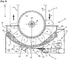
figure 2 est une illustration schématique pour exemple de la base d'un élévateur à godets conforme à l'invention, logeant un appareil de dispersion par percussion d'un reliquat de granulat en fond d'une cuve équipant ledit élévateur à godets, selon un exemple de réalisation d'un tel appareil qui est conforme à l'invention. - La
figure 3 est une illustration de modalités de réglage d'un écart de séparation entre des godets et une paroi de fond de la cuve que comprend l'élévateur à godets représenté sur lafigure 2 . - Les figures et leurs descriptions détaillées non limitatives, exposent l'invention selon des modalités particulières qui ne sont pas restrictives quant à la portée de l'invention telle que définie par les revendications. Les figures et leurs descriptions détaillées d'exemples de réalisation de l'invention peuvent servir à mieux la définir, si besoin en relation avec la description générale qui vient d'en être faite.
- Sur la
figure 1 , un exemple d'élévateur 1 à godets 2 relevant de l'art antérieur est représenté afin d'illustrer à titre indicatif non restrictif le contexte de la présente invention. Un tel élévateur 1 à godets 2 est typiquement utilisé dans le domaine agricole pour approvisionner un silo 3 en granulat 4 de céréales ou par analogie en farine céréalière. L'élévateur 1 est agencé en une colonne 5 qui s'étend en élévation verticalement V1 depuis le sol. - La base 5a de la colonne 5 ménage une cuve 6 pourvue d'une bouche d'admission 7 du granulat 4 depuis l'extérieur de l'élévateur 1. Le sommet 5b de la colonne 5 ménage un déversoir 8 du granulat 4 vers le silo 3, via une bouche d'évacuation 8a du granulat 4 hors de l'élévateur 1. La colonne 5 loge un convoyeur 9 à godets 2 qui s'étend entre la cuve 6 et le déversoir 8, pour acheminer successivement par paquets et en vrac du granulat 4 depuis la cuve 6 vers le déversoir 8.
- Les godets 2 sont successivement répartis le long d'une sangle 10 pour leur entraînement entre la cuve 6 et le déversoir 8. La sangle 10 est refermée en boucle sur elle-même et est entrainée sur elle-même entre la cuve 6 et le déversoir 8, via des tambours 11a, 11b qui sont montés tournant sur la colonne 5, la sangle 10 circulant en périphérie des tambours 11a, 11b. Un tambour supérieur 11b est placé à l'extrémité supérieure de la sangle 10 et un tambour inférieur 11a est placé à l'extrémité inférieure de la sangle 10.
- La sangle 10 circule à l'intérieur de la cuve 6, en disposant les godets 2 en fond de cuve 6 pour prélever du granulat 4 préalablement introduit à l'intérieur de la cuve 6, successivement par paquets par piochage du granulat 4 en vrac par les godets 2. Les godets 2 sont ainsi successivement acheminés via la sangle 10 depuis la cuve 6 vers le déversoir 8, puis depuis le déversoir 8 vers la cuve 6. Le granulat 4 admis à l'intérieur de la cuve 6 est collecté en continu en vrac et par parquets de granulats 4 successivement piochés en fond de cuve 6 par les godets 2, pour leur convoyage depuis la cuve 6 vers le sommet 5b de la colonne 5 et leur évacuation hors de l'élévateur 1 vers le silo 3 via le déversoir 8.
- La sangle 10 est maintenue en tension entre ses extrémités en périphérie des tambours 11a, 11b, via un premier dispositif de réglage 12 de la mise sous tension de la sangle 10 à un seuil d'effort de consigne. Un tel premier dispositif de réglage 12 est couramment agencé en organe procurant un éloignement des tambours 11a, 11b verticalement V1 l'un de l'autre, par exemple à partir d'un montage en mobilité verticale V1 et d'un blocage en position de l'un au moins des tambours 11a, 11b sur la colonne 5.
- Un écart E1 vertical V1 est maintenu entre les godets 2 balayant le fond de la cuve 6 et une paroi de fond 13 de la cuve 6 sur laquelle repose le granulat, pour ne pas faire obstacle à la circulation des godets 2 à l'intérieur de la cuve 6. Cependant, un tel écart E1 ménage en fond de cuve 6 une capacité à l'intérieur de laquelle un reliquat 14 de granulat 4 est susceptible de stagner, comme illustré sur la
figure 2 , ce que l'invention propose d'éviter. - A cet effet, un exemple de réalisation de l'invention est illustré sur la
figure 2 et lafigure 3 , à titre non restrictif, qui représentent un agencement particulier de la base 5a de la colonne 5 d'un élévateur 1 à godets 2 relevant de l'invention, équipé d'un appareil 15 conforme à un exemple de réalisation de l'invention. Pour décrire l'invention en relation avec lesfigures 2 et3 , les numéros de référence utilisés sur lafigure 1 sont conservés pour l'identification des notions et/ou des éléments communs à l'art antérieur et à l'invention. - Tel que précédemment décrit et pour préciser, un élévateur 1 à godets 2 relevant de l'invention et illustré partiellement sur les
figures 2 et3 , ménage à la base 5a d'une colonne 5 une cuve 6 de réception en son fond d'un granulat 4 à acheminer vers un déversoir 8 via un convoyeur 9 à godets 2. Le granulat 4 repose à l'intérieur de la cuve 6 sur la paroi de fond 13 qu'elle comporte et le convoyeur 9 à godets 2 s'étend verticalement V1 en élévation à l'intérieur de la colonne 5. - Le convoyeur 9 à godets 2 comprend essentiellement les godets 2 qui sont répartis le long de la sangle 10 refermée en boucle sur elle-même, ou tout autre organe analogue comme par exemple un jeu de courroies ou de chaînes. La sangle 10 circule à ses extrémités respectives en périphérie des tambours 11a, 11b d'entraînement et/ou de guidage de la sangle 10, dont le tambour inférieur 11a comme illustré.
- Un écart E1 vertical V1 est ménagé entre la paroi de fond 13 de la cuve 6 les godets 2 lors de leur passage en fond de cuve 6. La présence d'un tel écart E1 ménage une capacité de rétention d'un reliquat 14 de granulat 4, dont la stagnation en fond de cuve 6 est à éviter.
- Dans ce contexte sur la
figure 2 , il est proposé par l'invention un appareil 15 de dispersion du reliquat 14 de granulat 4 susceptible de stagner en fond de la cuve 6. La paroi de fond 13 de la cuve 6 est une paroi rigide, qui est notamment formée d'une tôle de conformation arquée. La paroi de fond 13 est ainsi sensiblement centrée sur l'axe A1 de rotation du tambour inférieur 11a, de manière à favoriser le prélèvement du granulat 4 par piochage en fond de cuve 6 via les godets 2. - L'appareil 15 comprend des percuteurs 16a, 16b heurtant séquentiellement la paroi de fond 13 de la cuve 6 pour refouler les grains dudit reliquat 14 vers les godets 2 lors de leur passage en fond de la cuve 6. Les percuteurs 16a, 16b sont mis en mobilité par une motorisation 17 comprenant un moteur 17a équipé d'une servocommande 17b, qui manoeuvre un organe d'entraînement 17c en mobilité des percuteurs 16a, 16b entre une station inactive et une station active de percussion de la paroi de fond 13 de la cuve 6.
- L'appareil 15 est logé à l'intérieur d'un caisson 18 ménageant une enceinte entourant la cuve 6, à laquelle le caisson 18 est fixé de manière réversible tel que par exemple par boulonnage. Le caisson 18 est fixé à la paroi périphérique 6a latérale de la cuve 6, de sorte que les percuteurs 16a, 16b sont placés en une position prédéfinie sous la paroi de fond 13 de la cuve 6. L'appareil 15 est disposé en contrebas à distance verticale V1 de la paroi de fond 13 de la cuve 6, en autorisant une mise en mobilité B1 des percuteurs 16a, 16b entre leur station inactive et leur station active, tel que par basculement B1 selon l'exemple illustré.
- La solidarisation entre la cuve 6 et le caisson 18 permet de garantir un positionnement correct des percuteurs 16a, 16b par rapport à la paroi de fond 13 de la cuve 6, pour finalement garantir la frappe de la paroi de fond 13 de la cuve 6 par les percuteurs 16a, 16b lors de la mise en oeuvre de l'appareil 15. L'installation de l'appareil 15 hors du volume de la cuve 6 évite aussi une implantation inopportune sur la paroi de fond 13 d'une masse pesante qui serait susceptible de la fragiliser, et permet aussi d'éviter tout contact entre l'appareil 15 et le granulat 14 contenu à l'intérieur de la cuve 6.
- Les percuteurs 16a, 16b comprennent chacun une masse de frappe 19 qui est notamment disposée sous la paroi de fond 13 de la cuve 6 en aval des godets 2 suivant le sens S1 de circulation de la sangle 10 en périphérie du tambour inférieur 11a et par rapport à un axe vertical AV1 de positionnement sur la colonne 5 de l'axe de rotation A1 du tambour inférieur 11a.
- Les masses de frappe 19 respectives des percuteurs 16a, 16b sont disposées à distance l'une de l'autre suivant le sens S1 de circulation de la sangle 10 en périphérie du tambour inférieur 11a, ledit sens S1 étant globalement orienté perpendiculairement à une orientation de mise en mobilité B1 par basculement des percuteurs 16a, 16b via la motorisation 17. Ceci procure un refoulement efficace et une collecte confortée du granulat 4 vers les godets 2, notamment ceux dont le débouché est orienté proche des percuteurs 16a, 16b préalablement à leur remontée vers le déversoir 8.
- Selon l'exemple de réalisation illustré, les percuteurs 16a, 16b sont chacun agencés en marteau comprenant un bras 20 dont l'une première des extrémités est munie d'une masse de frappe 19 et dont l'autre deuxième extrémité est fixée à l'organe d'entraînement 17c. Les percuteurs 16a, 16b sont montés mobiles B1 en basculement entre leur station active et leur station inactive, via un arbre 21 constitutif dudit organe d'entraînement 17c qui est monté tournant sur un palier 21b.
- Le moteur 17a est formé d'un vérin 17d manoeuvrable en translation T1 par aller-retour répétés sous contrôle de la servocommande 17b, provoquant une mise en pivotement de l'arbre 21 suivant des sens de rotation alternés, qui entraîne alors en mobilité B1 par basculement alterné les percuteurs 16a, 16b entre leur station active et leur station inactive.
- Les bras 20 des percuteurs 16a, 16b sont avantageusement flexibles, tout en présentant une raideur naturelle suffisante pour résister au poids de la masse de frappe 19 à leur première extrémité. La flexibilité des bras 20 permet de garantir la faculté des percuteurs 16a, 16b à heurter la paroi de fond 13 de la cuve 6, quel que soit raisonnablement la position verticale V1 de la cuve 6 par rapport aux percuteurs 16a, 16b. La flexibilité des bras 20 favorise aussi une accélération des masses de frappe 19 lors de la mise en mobilité des percuteurs 16a, 16b, ce qui permet d'accroître l'énergie transmise à la paroi de fond 13 de la cuve 6 lors de sa frappe par les percuteurs 16a, 16b.
- En phase de vidange de la cuve 6, les godets 2 sont entraînés en mobilité entre la cuve 6 et le déversoir 8 pour récupérer un reliquat 14 de granulat 4 présent en fond de cuve 6. La mise en oeuvre de l'appareil 15 est commandée, via la servocommande 17b, pour repousser les grains composant le reliquat 14 de granulat 4 vers les godets 2 lors de leur passage en fond de cuve 6. Le moteur 17a est activé pour provoquer, sous contrôle de la servocommande 17b, des heurts séquentiellement répétés à fréquences constantes ou variables, de la paroi de fond 13 de la cuve 6 par les percuteurs 16a, 16b provoquant un refoulement vers les godets 2 des grains dudit reliquat 14 de granulat 4 jusqu'à son épuisement.
- Sur la
figure 3 , le convoyeur 9 est équipé d'un dit premier dispositif de réglage 12 de la mise sous tension de la sangle 10 à un seuil d'effort de consigne. - Le premier dispositif de réglage 12 comprend une première tige filetée 12a munie d'un premier jeu d'écrous 12b d'immobilisation de la première tige filetée 12a, d'une part sur un premier support 12c équipant la colonne 5 et d'autre part sur une armature 22 de montage sur la colonne 5 d'un ensemble d'organes comprenant un palier 23 de montage tournant du tambour inférieur 11a sur la colonne 5. L'éloignement vertical V1 entre le tambour supérieur 11b et le tambour inférieur 11a peut être réglé, via les écrous du premier jeu d'écrous 12b, par adaptation de l'extension verticale V1 de la première tige filetée 12a entre le premier support 12c et l'armature 22.
- Le convoyeur 9 est par ailleurs équipé d'un deuxième dispositif de réglage 24 de la distance de séparation E1 entre la paroi de fond 13 de la cuve 6 et les godets 2 lors de leur passage en fond de cuve 6.
- A cet effet, ledit ensemble d'organes comprend non seulement le palier 23 de montage tournant du tambour inférieur 11a sur la colonne 5 mais aussi la cuve 6. Dès lors, il est compris ici que le réglage de la distance de séparation entre le tambour supérieur 11b et le tambour inférieur 11a, est réalisé via le premier dispositif de réglage 12 qui provoque une mobilité relative verticalement V1 entre d'une part le tambour supérieur 11b et d'autre part conjointement le tambour inférieur 11a et la cuve 6, via le palier 23 de montage du tambour inférieur 11a sur la colonne 5.
- Le deuxième dispositif de réglage 24 comprend une deuxième tige filetée 24a munie d'un deuxième jeu d'écrous 24b d'immobilisation de la deuxième tige filetée 24a, d'une part sur ladite armature 22 et d'autre part sur un deuxième support 24c équipant le palier 23 de montage du tambour inférieur 11a sur la colonne 5. L'ajustement de la distance de séparation E1 entre la paroi de fond 13 de la cuve 6 et les godets 2 lors de leur passage en fond de cuve 6 est réalisé par réglage, via les écrous du deuxième jeu d'écrous 24b, de l'extension verticale V1 de la deuxième tige filetée 24a entre l'armature 22 et le deuxième support 24c.
- Ceci permet de limiter la capacité de la cuve 6 à l'intérieur de laquelle un reliquat 14 de granulat 4 est susceptible de stagner en fond de cuve 6, et cela quel que soit l'effort de mise sous tension de la sangle 10 à un seuil d'effort de consigne via le premier dispositif de réglage 12. Un prélèvement optimisé du granulat 4 par les godets 2 est ainsi favorisé, ce qui limite le volume d'un reliquat 14 de granulat 4 susceptible de stagner en fond de cuve 6 et ce qui facilite le refoulement vers les godets 2 des grains composant un tel reliquat 14 de granulat 4 par suite de la percussion de la paroi de fond 13 par les percuteurs 16a, 16b.
Claims (14)
- Appareil (15) de dispersion d'un reliquat (14) de granulat (4) en fond de cuve (6) d'un élévateur (1) à godets (2), ledit appareil (15) comprenant un organe générateur de vibrations d'une paroi de fond (13) de la cuve (6), caractérisé en ce que l'organe générateur de vibrations comprend au moins un percuteur (16a, 16b) et une motorisation (17) de mise en mobilité séquentielle dudit au moins un percuteur (16a, 16b) entre une station inactive du percuteur (16a, 16b), dans laquelle le percuteur (16a, 16b) est en position stable, et une station active du percuteur (16a, 16b), dans laquelle le percuteur (16a, 16b) est entraîné en mobilité par la motorisation (17).
- Appareil (15) selon la revendication 1, caractérisé en ce que ledit au moins un percuteur (16a, 16b) est monté mobile (B1) sur l'appareil (15) entre sa station active et sa station inactive, via un organe d'entraînement (17c) dudit au moins un percuteur (16a, 16b) qui est mû par un moteur (17b) que comprend ladite motorisation (17).
- Appareil (15) selon la revendication 2, caractérisé en ce que ledit au moins un percuteur (16a, 16b) est monté élastiquement mobile (B1) sur l'appareil (15), via un organe élastiquement déformable (20) interposé entre le dit organe d'entraînement (17c) et au moins une masse de frappe (19) que comprend le percuteur (16a, 16b).
- Appareil (15) selon la revendication 3, caractérisé en ce que ledit au moins un percuteur (16a, 16b) est agencé en marteau mobile (B1) en basculement, comprenant au moins une masse de frappe (19) qui est montée à une première extrémité d'un bras (20) dont l'autre deuxième extrémité est reliée audit organe d'entraînement (17c).
- Appareil (15) selon la revendication 4, caractérisé en ce que le bras (20) forme au moins en partie ledit organe élastiquement déformable, en étant flexible entre ses extrémités et générateur en station active d'une mobilité (B1) en basculement élastique du percuteur (16a, 16b) via ledit organe d'entraînement (17c).
- Appareil (15) selon l'une quelconque des revendications 3 à 5, caractérisé en ce que les percuteurs (16a, 16b) sont en pluralité, les masses de frappe (19) respectives d'au moins deux percuteurs (16a, 16b) étant distantes l'une de l'autre suivant au moins une direction concourante à une orientation de mises en mobilité individuelles des percuteurs (16a, 16b) entre leur station inactive et leur station active.
- Appareil (15) selon les revendications 2 à 4, caractérisé en ce que ledit moteur (17a) est formé d'un vérin d'entraînement séquentiel en pivotement alterné d'un arbre tournant (21) constitutif dudit organe d'entraînement (17c), via lequel arbre tournant (21) une pluralité de percuteurs (16a, 16b) sont individuellement mis en mobilité entre leur station inactive et leur station active suivant des cinématiques propres qui sont différenciées.
- Elévateur (1) à godets (2) comprenant une colonne (5) s'étendant en élévation verticalement (V1) par rapport au sol et logeant un convoyeur (9) à godets (2) comprenant une sangle (10) qui est refermée en boucle sur elle-même et le long de laquelle sont répartis des godets (2), les extrémités de la sangle (10) s'étendant respectivement en périphérie d'un tambour supérieur (11b) ménagé tournant au sommet (5b) de la colonne (5) et d'un tambour inférieur (11a) ménagé tournant à la base (5a) de la colonne (5), la sangle (10) étant entraînée en mobilité sur elle-même via l'un au moins desdits tambours (11a, 11b) qui est motorisé en rotation, une cuve (6) de réception d'un granulat (4) à convoyer vers le sommet (5b) de la colonne (5), via lesdits godets (2), étant ménagée à la base (5a) de la colonne (5) et comprenant une paroi de fond (13), caractérisé en ce que l'élévateur (1) est équipé d'au moins un appareil (15) selon l'une quelconque des revendications 1 à 7 qui est disposé à l'extérieur de la cuve (6), ladite motorisation (17) de l'appareil (15) étant disposée à distance en contrebas de la paroi de fond (13) de la cuve (6) et ledit au moins un percuteur (16a, 16b) s'étendant sous la paroi de fond (13) de la cuve (6) qui est formée d'une tôle arquée suivant le trajet suivi par la sangle (10) en périphérie du tambour inférieur (11a).
- Elévateur (1) à godets (2) selon la revendication 8, caractérisé en ce que l'appareil (15) est installé à l'intérieur d'un caisson (18) qui s'étend sous la cuve (6) en étant fixé en suspension sur une paroi latérale (6a) de la cuve (6) par brochage réversible.
- Elévateur (1) à godets (2) selon l'une quelconque des revendications 8 et 9, caractérisé :en ce que la cuve (6) et un palier (23) de montage tournant du tambour inférieur (11a) sur la colonne (5) forme au moins en partie un ensemble d'organes (23, 6) qui est monté en mobilité verticale (V1) sur la colonne(5), via un premier dispositif de réglage (12) d'une mise sous tension de la sangle (10) entre ses extrémités par éloignement vertical (V1) dudit ensemble d'organes (23, 6) par rapport au tambour supérieur(11b), eten ce que l'élévateur est équipé d'un deuxième dispositif de réglage (24) de la distance (E1) de séparation entre la paroi de fond (13) de la cuve (6) et les godets (2) lors de leur passage en fond de cuve (6), par montage en mobilité relative entre la cuve (6) et le palier (23) du tambour inférieur (11a), verticalement (V1) au sein dudit ensemble d'organes (23, 6).
- Elévateur (1) à godets (2) selon l'une quelconque des revendications 8 à 10, caractérisé en ce que ledit au moins un percuteur (16a, 16b) est placé sous la paroi de fond (13) de la cuve (6) en aval des godets (2) suivant le sens (S1) de circulation de la sangle (10) en périphérie du tambour inférieur (11a) et par rapport à un axe vertical (AV1) de positionnement sur la colonne (5) de l'axe de rotation (A1) du tambour inférieur (11a).
- Elévateur (1) à godets (2) selon l'une quelconque des revendications 8 à 11, caractérisé en ce que l'appareil (15) comprenant plusieurs percuteurs (16a, 16b) chacun munis d'au moins une masse de frappe (19), les masses de frappe (19) respectives d'au moins deux percuteurs (16a, 16b) sont distantes l'une de l'autre au moins suivant le sens (S1) de circulation de la sangle (10) en périphérie du tambour inférieur (11a).
- Procédé de mise en oeuvre d'un appareil (15) selon l'une quelconque des revendications 1 à 7 équipant un élévateur (1) à godets (2) selon l'une quelconque des revendications 8 à 12, caractérisé en ce que le procédé comprend une opération de frappe séquentielle de la paroi de fond (13) de la cuve (6) par ledit au moins un percuteur (16a, 16b) mis en mobilité (B1) entre sa station inactive et sa station active par ladite motorisation (17) que comprend l'appareil (15), la frappe de la paroi de fond (13) de la cuve (6) par ledit au moins un percuteur (16a, 16b) étant génératrice d'une mise en résonance de la paroi de fond (13) de la cuve (6) qui provoque un refoulement d'un reliquat (14) de granulat (4) en fond de cuve (6) vers les godets (2) circulant en fond de cuve (6) en surplomb de sa paroi de fond (13).
- Procédé selon la revendication 13, de mise en oeuvre d'un appareil (15) équipant un élévateur (1) à godets (2) selon la revendication 9, caractérisé en ce que le procédé comprend une opération de calibrage de l'appareil (15) selon laquelle ledit au moins un percuteur (16a, 16b) est positionné en station inactive par rapport à la paroi de fond (13) de la cuve (6), par montage dudit caisson (18) sur la cuve (6) en une position prédéfinie, à l'intérieur duquel caisson (18) l'appareil (15) est lui-même installable en une position prédéfinie.
Applications Claiming Priority (1)
| Application Number | Priority Date | Filing Date | Title |
|---|---|---|---|
| FR1874004A FR3090602B1 (fr) | 2018-12-21 | 2018-12-21 | Appareil à percussion de mise en mouvement d'un résidu de granulat en fond de cuve d'un élévateur à godets, et élévateur à godets de convoyage d'un granulat équipé d'un tel appareil. |
Publications (3)
| Publication Number | Publication Date |
|---|---|
| EP3670394A1 true EP3670394A1 (fr) | 2020-06-24 |
| EP3670394B1 EP3670394B1 (fr) | 2025-07-02 |
| EP3670394C0 EP3670394C0 (fr) | 2025-07-02 |
Family
ID=66867307
Family Applications (1)
| Application Number | Title | Priority Date | Filing Date |
|---|---|---|---|
| EP19201131.0A Active EP3670394B1 (fr) | 2018-12-21 | 2019-10-02 | Élévateur à godets de convoyage d'un granulat équipé d'un appareil à percussion de mise en mouvement d'un résidu de granulat en fond de cuve et procédé de mise en oeuvre d'un tel appareil |
Country Status (2)
| Country | Link |
|---|---|
| EP (1) | EP3670394B1 (fr) |
| FR (1) | FR3090602B1 (fr) |
Cited By (4)
| Publication number | Priority date | Publication date | Assignee | Title |
|---|---|---|---|---|
| CN114379994A (zh) * | 2022-01-14 | 2022-04-22 | 湖南创意雷家岭农业股份有限公司 | 一种可除杂的谷物加工用提升运输装置 |
| CN114560315A (zh) * | 2022-03-25 | 2022-05-31 | 青海丽豪半导体材料有限公司 | 一种硅粉运输抬升装置 |
| RU2807776C1 (ru) * | 2023-02-20 | 2023-11-21 | Федеральное государственное автономное образовательное учреждение высшего образования "Сибирский федеральный университет" | Стенд для испытания рабочих элементов ковшового элеватора |
| CN119976178A (zh) * | 2025-04-14 | 2025-05-13 | 广东吉多宝制罐有限公司 | 一种用于铝制易拉罐空罐生产的提升机 |
Families Citing this family (1)
| Publication number | Priority date | Publication date | Assignee | Title |
|---|---|---|---|---|
| CN117184764A (zh) * | 2023-11-06 | 2023-12-08 | 福建省锅炉压力容器检验研究院泉州分院 | 一种锅炉斗式提升机 |
Citations (5)
| Publication number | Priority date | Publication date | Assignee | Title |
|---|---|---|---|---|
| CH264790A (fr) * | 1945-02-22 | 1949-10-31 | Diebold & Cie Sa | Elévateur mécanique continu de produits granuleux. |
| SU831672A1 (ru) | 1976-12-08 | 1981-05-23 | Всесоюзный Научно-Исследовательскийинститут Линейного Машиностроения,Литейной Технологии И Автоматизациилитейного Производства "Вниилитмаш" | Вертикальный ковшовый элеватор |
| JPS6071410A (ja) | 1983-09-29 | 1985-04-23 | Satake Eng Co Ltd | バケツトコンベア |
| JP2697339B2 (ja) | 1990-08-10 | 1998-01-14 | 日立金属株式会社 | バケットエレベータのクリーニング運転方法 |
| CN108945849A (zh) * | 2018-07-30 | 2018-12-07 | 河南省交通建设工程有限公司 | 公路施工现场用防堵塞、无扬尘式水泥转运罐 |
-
2018
- 2018-12-21 FR FR1874004A patent/FR3090602B1/fr active Active
-
2019
- 2019-10-02 EP EP19201131.0A patent/EP3670394B1/fr active Active
Patent Citations (5)
| Publication number | Priority date | Publication date | Assignee | Title |
|---|---|---|---|---|
| CH264790A (fr) * | 1945-02-22 | 1949-10-31 | Diebold & Cie Sa | Elévateur mécanique continu de produits granuleux. |
| SU831672A1 (ru) | 1976-12-08 | 1981-05-23 | Всесоюзный Научно-Исследовательскийинститут Линейного Машиностроения,Литейной Технологии И Автоматизациилитейного Производства "Вниилитмаш" | Вертикальный ковшовый элеватор |
| JPS6071410A (ja) | 1983-09-29 | 1985-04-23 | Satake Eng Co Ltd | バケツトコンベア |
| JP2697339B2 (ja) | 1990-08-10 | 1998-01-14 | 日立金属株式会社 | バケットエレベータのクリーニング運転方法 |
| CN108945849A (zh) * | 2018-07-30 | 2018-12-07 | 河南省交通建设工程有限公司 | 公路施工现场用防堵塞、无扬尘式水泥转运罐 |
Cited By (6)
| Publication number | Priority date | Publication date | Assignee | Title |
|---|---|---|---|---|
| CN114379994A (zh) * | 2022-01-14 | 2022-04-22 | 湖南创意雷家岭农业股份有限公司 | 一种可除杂的谷物加工用提升运输装置 |
| CN114379994B (zh) * | 2022-01-14 | 2023-11-17 | 湖南创意雷家岭农业股份有限公司 | 一种可除杂的谷物加工用提升运输装置 |
| CN114560315A (zh) * | 2022-03-25 | 2022-05-31 | 青海丽豪半导体材料有限公司 | 一种硅粉运输抬升装置 |
| CN114560315B (zh) * | 2022-03-25 | 2024-03-26 | 青海丽豪半导体材料有限公司 | 一种硅粉运输抬升装置 |
| RU2807776C1 (ru) * | 2023-02-20 | 2023-11-21 | Федеральное государственное автономное образовательное учреждение высшего образования "Сибирский федеральный университет" | Стенд для испытания рабочих элементов ковшового элеватора |
| CN119976178A (zh) * | 2025-04-14 | 2025-05-13 | 广东吉多宝制罐有限公司 | 一种用于铝制易拉罐空罐生产的提升机 |
Also Published As
| Publication number | Publication date |
|---|---|
| EP3670394B1 (fr) | 2025-07-02 |
| FR3090602B1 (fr) | 2020-12-11 |
| EP3670394C0 (fr) | 2025-07-02 |
| FR3090602A1 (fr) | 2020-06-26 |
Similar Documents
| Publication | Publication Date | Title |
|---|---|---|
| EP3670394B1 (fr) | Élévateur à godets de convoyage d'un granulat équipé d'un appareil à percussion de mise en mouvement d'un résidu de granulat en fond de cuve et procédé de mise en oeuvre d'un tel appareil | |
| EP0007854B1 (fr) | Dispositif de répartition d'un solide divisé dans une enceinte | |
| CA2203727C (fr) | Procede et dispositif pour le chargement homogene de particules d'un catalyseur solide dans un reacteur tubulaire | |
| LU85767A1 (fr) | Dispositif de reglage du temps de retention du materiau dans un broyeur | |
| CN1091715A (zh) | 运输机皮带刮削装置 | |
| US20220203374A1 (en) | Horizontal shaft impact crusher systems, methods and apparatus | |
| US20040050987A1 (en) | Mobile jaw crusher assembly | |
| FR2963209A1 (fr) | Machine d'egrappage comprenant une cage | |
| FR2962991A1 (fr) | Dispositif de chargement pour du produit en vrac | |
| JP6967786B2 (ja) | 養殖籠における貝類の回収装置 | |
| CN119953906B (zh) | 一种基于面粉加工用的毛麦输送装置及方法 | |
| FR2963743A1 (fr) | Dispositif d'alimentation mobile d'un concasseur ou broyeur a marteaux, dechiqueteur ou analogue | |
| FR2660213A1 (fr) | Broyeur a marteaux, a alimentation centrale, pour le dechiquetage d'objets metalliques. | |
| FR2518969A1 (fr) | Dechargement pneumatique de navires | |
| CN105398779A (zh) | 一种带有抖料装置的斗式提升机 | |
| CA2746697C (fr) | Broyeur de faible encombrement muni d'un rotor incline par rapport a l'axe de la goulotte d'alimentation | |
| RU2344239C1 (ru) | Рабочий орган карьерного экскаватора | |
| CN114700161A (zh) | 一种固定式给料破碎机组设备及给料方法 | |
| JP5031385B2 (ja) | リサイクル機械及び自走式破砕機 | |
| US2578058A (en) | Closure operator for ditching wheel bucket backs | |
| LU79920A1 (fr) | Broyeur-concasseur a marteaux articules | |
| US1021760A (en) | Elevator and conveyer. | |
| RU2516287C2 (ru) | Способ обмолота и сепарации зерновых и масличных культур и молотильно-сепарирующее устройство | |
| FR2480630A1 (fr) | Vibrateur | |
| FR2638662A1 (fr) | Broyeur a marteaux, a alimentation centrale, pour le dechiquetage d'objets metalliques |
Legal Events
| Date | Code | Title | Description |
|---|---|---|---|
| PUAI | Public reference made under article 153(3) epc to a published international application that has entered the european phase |
Free format text: ORIGINAL CODE: 0009012 |
|
| STAA | Information on the status of an ep patent application or granted ep patent |
Free format text: STATUS: THE APPLICATION HAS BEEN PUBLISHED |
|
| AK | Designated contracting states |
Kind code of ref document: A1 Designated state(s): AL AT BE BG CH CY CZ DE DK EE ES FI FR GB GR HR HU IE IS IT LI LT LU LV MC MK MT NL NO PL PT RO RS SE SI SK SM TR |
|
| AX | Request for extension of the european patent |
Extension state: BA ME |
|
| STAA | Information on the status of an ep patent application or granted ep patent |
Free format text: STATUS: REQUEST FOR EXAMINATION WAS MADE |
|
| 17P | Request for examination filed |
Effective date: 20200730 |
|
| RBV | Designated contracting states (corrected) |
Designated state(s): AL AT BE BG CH CY CZ DE DK EE ES FI FR GB GR HR HU IE IS IT LI LT LU LV MC MK MT NL NO PL PT RO RS SE SI SK SM TR |
|
| STAA | Information on the status of an ep patent application or granted ep patent |
Free format text: STATUS: EXAMINATION IS IN PROGRESS |
|
| RIC1 | Information provided on ipc code assigned before grant |
Ipc: B65G 47/58 20060101ALI20221122BHEP Ipc: B65G 65/46 20060101ALI20221122BHEP Ipc: B65G 17/12 20060101ALI20221122BHEP Ipc: B65G 65/32 20060101ALI20221122BHEP Ipc: B65G 65/06 20060101ALI20221122BHEP Ipc: B65G 17/36 20060101AFI20221122BHEP |
|
| 17Q | First examination report despatched |
Effective date: 20221216 |
|
| RAP3 | Party data changed (applicant data changed or rights of an application transferred) |
Owner name: DENIS |
|
| GRAP | Despatch of communication of intention to grant a patent |
Free format text: ORIGINAL CODE: EPIDOSNIGR1 |
|
| STAA | Information on the status of an ep patent application or granted ep patent |
Free format text: STATUS: GRANT OF PATENT IS INTENDED |
|
| INTG | Intention to grant announced |
Effective date: 20250213 |
|
| GRAS | Grant fee paid |
Free format text: ORIGINAL CODE: EPIDOSNIGR3 |
|
| GRAA | (expected) grant |
Free format text: ORIGINAL CODE: 0009210 |
|
| STAA | Information on the status of an ep patent application or granted ep patent |
Free format text: STATUS: THE PATENT HAS BEEN GRANTED |
|
| AK | Designated contracting states |
Kind code of ref document: B1 Designated state(s): AL AT BE BG CH CY CZ DE DK EE ES FI FR GB GR HR HU IE IS IT LI LT LU LV MC MK MT NL NO PL PT RO RS SE SI SK SM TR |
|
| REG | Reference to a national code |
Ref country code: GB Ref legal event code: FG4D Free format text: NOT ENGLISH |
|
| REG | Reference to a national code |
Ref country code: CH Ref legal event code: EP |
|
| REG | Reference to a national code |
Ref country code: DE Ref legal event code: R096 Ref document number: 602019071868 Country of ref document: DE |
|
| REG | Reference to a national code |
Ref country code: IE Ref legal event code: FG4D Free format text: LANGUAGE OF EP DOCUMENT: FRENCH |
|
| U01 | Request for unitary effect filed |
Effective date: 20250711 |
|
| U07 | Unitary effect registered |
Designated state(s): AT BE BG DE DK EE FI FR IT LT LU LV MT NL PT RO SE SI Effective date: 20250716 |
|
| U20 | Renewal fee for the european patent with unitary effect paid |
Year of fee payment: 7 Effective date: 20251028 |
|
| PG25 | Lapsed in a contracting state [announced via postgrant information from national office to epo] |
Ref country code: IS Free format text: LAPSE BECAUSE OF FAILURE TO SUBMIT A TRANSLATION OF THE DESCRIPTION OR TO PAY THE FEE WITHIN THE PRESCRIBED TIME-LIMIT Effective date: 20251102 |
|
| PG25 | Lapsed in a contracting state [announced via postgrant information from national office to epo] |
Ref country code: NO Free format text: LAPSE BECAUSE OF FAILURE TO SUBMIT A TRANSLATION OF THE DESCRIPTION OR TO PAY THE FEE WITHIN THE PRESCRIBED TIME-LIMIT Effective date: 20251002 |
|
| PG25 | Lapsed in a contracting state [announced via postgrant information from national office to epo] |
Ref country code: HR Free format text: LAPSE BECAUSE OF FAILURE TO SUBMIT A TRANSLATION OF THE DESCRIPTION OR TO PAY THE FEE WITHIN THE PRESCRIBED TIME-LIMIT Effective date: 20250702 |
|
| PG25 | Lapsed in a contracting state [announced via postgrant information from national office to epo] |
Ref country code: GR Free format text: LAPSE BECAUSE OF FAILURE TO SUBMIT A TRANSLATION OF THE DESCRIPTION OR TO PAY THE FEE WITHIN THE PRESCRIBED TIME-LIMIT Effective date: 20251003 |
|
| PG25 | Lapsed in a contracting state [announced via postgrant information from national office to epo] |
Ref country code: CZ Free format text: LAPSE BECAUSE OF FAILURE TO SUBMIT A TRANSLATION OF THE DESCRIPTION OR TO PAY THE FEE WITHIN THE PRESCRIBED TIME-LIMIT Effective date: 20250702 |
|
| PG25 | Lapsed in a contracting state [announced via postgrant information from national office to epo] |
Ref country code: PL Free format text: LAPSE BECAUSE OF FAILURE TO SUBMIT A TRANSLATION OF THE DESCRIPTION OR TO PAY THE FEE WITHIN THE PRESCRIBED TIME-LIMIT Effective date: 20250702 |
|
| PG25 | Lapsed in a contracting state [announced via postgrant information from national office to epo] |
Ref country code: RS Free format text: LAPSE BECAUSE OF FAILURE TO SUBMIT A TRANSLATION OF THE DESCRIPTION OR TO PAY THE FEE WITHIN THE PRESCRIBED TIME-LIMIT Effective date: 20251002 |
|
| PG25 | Lapsed in a contracting state [announced via postgrant information from national office to epo] |
Ref country code: ES Free format text: LAPSE BECAUSE OF FAILURE TO SUBMIT A TRANSLATION OF THE DESCRIPTION OR TO PAY THE FEE WITHIN THE PRESCRIBED TIME-LIMIT Effective date: 20250702 |
|
| PG25 | Lapsed in a contracting state [announced via postgrant information from national office to epo] |
Ref country code: SM Free format text: LAPSE BECAUSE OF FAILURE TO SUBMIT A TRANSLATION OF THE DESCRIPTION OR TO PAY THE FEE WITHIN THE PRESCRIBED TIME-LIMIT Effective date: 20250702 |
|
| PG25 | Lapsed in a contracting state [announced via postgrant information from national office to epo] |
Ref country code: SK Free format text: LAPSE BECAUSE OF FAILURE TO SUBMIT A TRANSLATION OF THE DESCRIPTION OR TO PAY THE FEE WITHIN THE PRESCRIBED TIME-LIMIT Effective date: 20250702 |