EP3670368A1 - Product processing device - Google Patents
Product processing device Download PDFInfo
- Publication number
- EP3670368A1 EP3670368A1 EP18845963.0A EP18845963A EP3670368A1 EP 3670368 A1 EP3670368 A1 EP 3670368A1 EP 18845963 A EP18845963 A EP 18845963A EP 3670368 A1 EP3670368 A1 EP 3670368A1
- Authority
- EP
- European Patent Office
- Prior art keywords
- adjustment
- film
- packaging
- product processing
- processing apparatus
- Prior art date
- Legal status (The legal status is an assumption and is not a legal conclusion. Google has not performed a legal analysis and makes no representation as to the accuracy of the status listed.)
- Granted
Links
Images





Classifications
-
- B—PERFORMING OPERATIONS; TRANSPORTING
- B65—CONVEYING; PACKING; STORING; HANDLING THIN OR FILAMENTARY MATERIAL
- B65B—MACHINES, APPARATUS OR DEVICES FOR, OR METHODS OF, PACKAGING ARTICLES OR MATERIALS; UNPACKING
- B65B59/00—Arrangements to enable machines to handle articles of different sizes, to produce packages of different sizes, to vary the contents of packages, to handle different types of packaging material, or to give access for cleaning or maintenance purposes
- B65B59/003—Arrangements to enable adjustments related to the packaging material
-
- G—PHYSICS
- G05—CONTROLLING; REGULATING
- G05B—CONTROL OR REGULATING SYSTEMS IN GENERAL; FUNCTIONAL ELEMENTS OF SUCH SYSTEMS; MONITORING OR TESTING ARRANGEMENTS FOR SUCH SYSTEMS OR ELEMENTS
- G05B19/00—Program-control systems
- G05B19/02—Program-control systems electric
- G05B19/18—Numerical control [NC], i.e. automatically operating machines, in particular machine tools, e.g. in a manufacturing environment, so as to execute positioning, movement or co-ordinated operations by means of program data in numerical form
- G05B19/409—Numerical control [NC], i.e. automatically operating machines, in particular machine tools, e.g. in a manufacturing environment, so as to execute positioning, movement or co-ordinated operations by means of program data in numerical form characterised by using manual data input [MDI] or by using control panel, e.g. controlling functions with the panel; characterised by control panel details or by setting parameters
-
- B—PERFORMING OPERATIONS; TRANSPORTING
- B65—CONVEYING; PACKING; STORING; HANDLING THIN OR FILAMENTARY MATERIAL
- B65B—MACHINES, APPARATUS OR DEVICES FOR, OR METHODS OF, PACKAGING ARTICLES OR MATERIALS; UNPACKING
- B65B41/00—Supplying or feeding container-forming sheets or wrapping material
- B65B41/12—Feeding webs from rolls
- B65B41/16—Feeding webs from rolls by rollers
-
- B—PERFORMING OPERATIONS; TRANSPORTING
- B65—CONVEYING; PACKING; STORING; HANDLING THIN OR FILAMENTARY MATERIAL
- B65B—MACHINES, APPARATUS OR DEVICES FOR, OR METHODS OF, PACKAGING ARTICLES OR MATERIALS; UNPACKING
- B65B51/00—Devices for, or methods of, sealing or securing package folds or closures; Devices for gathering or twisting wrappers, or necks of bags
- B65B51/10—Applying or generating heat or pressure or combinations thereof
- B65B51/26—Devices specially adapted for producing transverse or longitudinal seams in webs or tubes
- B65B51/30—Devices, e.g. jaws, for applying pressure and heat, e.g. for subdividing filled tubes
- B65B51/306—Counter-rotating devices
-
- B—PERFORMING OPERATIONS; TRANSPORTING
- B65—CONVEYING; PACKING; STORING; HANDLING THIN OR FILAMENTARY MATERIAL
- B65B—MACHINES, APPARATUS OR DEVICES FOR, OR METHODS OF, PACKAGING ARTICLES OR MATERIALS; UNPACKING
- B65B57/00—Automatic control, checking, warning, or safety devices
-
- B—PERFORMING OPERATIONS; TRANSPORTING
- B65—CONVEYING; PACKING; STORING; HANDLING THIN OR FILAMENTARY MATERIAL
- B65B—MACHINES, APPARATUS OR DEVICES FOR, OR METHODS OF, PACKAGING ARTICLES OR MATERIALS; UNPACKING
- B65B57/00—Automatic control, checking, warning, or safety devices
- B65B57/02—Automatic control, checking, warning, or safety devices responsive to absence, presence, abnormal feed, or misplacement of binding or wrapping material, containers, or packages
- B65B57/04—Automatic control, checking, warning, or safety devices responsive to absence, presence, abnormal feed, or misplacement of binding or wrapping material, containers, or packages and operating to control, or to stop, the feed of such material, containers, or packages
-
- B—PERFORMING OPERATIONS; TRANSPORTING
- B65—CONVEYING; PACKING; STORING; HANDLING THIN OR FILAMENTARY MATERIAL
- B65B—MACHINES, APPARATUS OR DEVICES FOR, OR METHODS OF, PACKAGING ARTICLES OR MATERIALS; UNPACKING
- B65B59/00—Arrangements to enable machines to handle articles of different sizes, to produce packages of different sizes, to vary the contents of packages, to handle different types of packaging material, or to give access for cleaning or maintenance purposes
-
- B—PERFORMING OPERATIONS; TRANSPORTING
- B65—CONVEYING; PACKING; STORING; HANDLING THIN OR FILAMENTARY MATERIAL
- B65B—MACHINES, APPARATUS OR DEVICES FOR, OR METHODS OF, PACKAGING ARTICLES OR MATERIALS; UNPACKING
- B65B61/00—Auxiliary devices, not otherwise provided for, for operating on sheets, blanks, webs, binding material, containers or packages
- B65B61/02—Auxiliary devices, not otherwise provided for, for operating on sheets, blanks, webs, binding material, containers or packages for perforating, scoring, slitting, or applying code or date marks on material prior to packaging
- B65B61/025—Auxiliary devices, not otherwise provided for, for operating on sheets, blanks, webs, binding material, containers or packages for perforating, scoring, slitting, or applying code or date marks on material prior to packaging for applying, e.g. printing, code or date marks on material prior to packaging
-
- B—PERFORMING OPERATIONS; TRANSPORTING
- B65—CONVEYING; PACKING; STORING; HANDLING THIN OR FILAMENTARY MATERIAL
- B65B—MACHINES, APPARATUS OR DEVICES FOR, OR METHODS OF, PACKAGING ARTICLES OR MATERIALS; UNPACKING
- B65B9/00—Enclosing successive articles, or quantities of material, e.g. liquids or semiliquids, in flat, folded, or tubular webs of flexible sheet material; Subdividing filled flexible tubes to form packages
- B65B9/10—Enclosing successive articles, or quantities of material, in preformed tubular webs, or in webs formed into tubes around filling nozzles, e.g. extruded tubular webs
- B65B9/20—Enclosing successive articles, or quantities of material, in preformed tubular webs, or in webs formed into tubes around filling nozzles, e.g. extruded tubular webs the webs being formed into tubes in situ around the filling nozzles
- B65B9/207—Enclosing successive articles, or quantities of material, in preformed tubular webs, or in webs formed into tubes around filling nozzles, e.g. extruded tubular webs the webs being formed into tubes in situ around the filling nozzles the web advancing continuously
-
- G—PHYSICS
- G05—CONTROLLING; REGULATING
- G05B—CONTROL OR REGULATING SYSTEMS IN GENERAL; FUNCTIONAL ELEMENTS OF SUCH SYSTEMS; MONITORING OR TESTING ARRANGEMENTS FOR SUCH SYSTEMS OR ELEMENTS
- G05B2219/00—Program-control systems
- G05B2219/30—Nc systems
- G05B2219/36—Nc in input of data, input key till input tape
- G05B2219/36061—Storage, memory area to store history data for previous corrections, editable
-
- G—PHYSICS
- G05—CONTROLLING; REGULATING
- G05B—CONTROL OR REGULATING SYSTEMS IN GENERAL; FUNCTIONAL ELEMENTS OF SUCH SYSTEMS; MONITORING OR TESTING ARRANGEMENTS FOR SUCH SYSTEMS OR ELEMENTS
- G05B2219/00—Program-control systems
- G05B2219/30—Nc systems
- G05B2219/36—Nc in input of data, input key till input tape
- G05B2219/36089—Machining parameters, modification during operation
-
- G—PHYSICS
- G05—CONTROLLING; REGULATING
- G05B—CONTROL OR REGULATING SYSTEMS IN GENERAL; FUNCTIONAL ELEMENTS OF SUCH SYSTEMS; MONITORING OR TESTING ARRANGEMENTS FOR SUCH SYSTEMS OR ELEMENTS
- G05B2219/00—Program-control systems
- G05B2219/30—Nc systems
- G05B2219/45—Nc applications
- G05B2219/45048—Packaging
Definitions
- the present invention relates to a product processing apparatus for packaging products in film or the like or box packing products into cardboard boxes or the like.
- Bag-making and packaging machines for packaging products in film or the like have mechanisms requiring manual adjustment when switching a setting relating to the packaging of the products.
- Examples of such mechanisms include a roller that guides the film paid out from a film roll and a printing device for printing predetermined information on the film that is being conveyed.
- a printing device such as disclosed in patent document 1 ( JP-A No. 2006-36246 )
- JP-A No. 2006-36246 when switching the setting, the worker has manually adjusted the position of the head of the printing device.
- the worker has written down on a paper memo, for example, the mechanisms requiring manual adjustment when switching the setting and performed the required adjustments while referring to the memo.
- a product processing apparatus pertaining to the invention is an apparatus that performs packaging or box packing of products, and has a storage component and a display component.
- the storage component stores settings relating to the packaging or the box packing of the products.
- the display component displays adjustment-requiring parts requiring adjustment in the apparatus when changing the settings relating to the packaging or the box packing of the products.
- This product processing apparatus has the function of displaying on a display or the like and notifying the user of information relating to parts requiring manual adjustment when switching the settings relating to the packaging or the box packing of the products. Consequently, this product processing apparatus has the function of preventing the user from forgetting to adjust a part that needs to be manually adjusted when switching the settings relating to the packaging or the box packing of the products.
- the display component further display setting values for the adjustment-requiring parts after the change in the settings.
- the product processing apparatus further have a setting value input component for inputting the setting values per each of the settings.
- the display component display, in a manner different from other of the adjustment-requiring parts, the adjustment-requiring parts for which the setting values differ between before changing and after changing the settings.
- the product processing apparatus can notify the user, in a way that is easy to understand, of the parts requiring a change in their setting values.
- the product processing apparatus further have an adjustment complete input component for inputting that adjustment of the adjustment-requiring parts has been completed.
- the user can relay to the apparatus that the user has completed the adjustment of the adjustment-requiring parts and confirm the adjustment work.
- the product processing apparatus can start the packaging or the box packing of the products after the adjustment work by the user has reliably ended.
- the product processing apparatus further have a display manner changing component for causing the display component to display, in a manner different from the adjustment-requiring parts for which adjustment has not been completed, the adjustment-requiring parts for which adjustment has been completed when changing the settings.
- the product processing apparatus is an apparatus that packages the products in film, and has a conveyance unit, a roller, and a printing unit.
- the conveyance unit conveys the film in its longitudinal direction.
- the roller guides the film that is being conveyed.
- the printing unit prints predetermined information on the film that is being conveyed.
- the display component displays, as the adjustment-requiring parts, at least one of the position of the roller, the width direction position of the film that is being conveyed, and the position where the printing unit prints on the film.
- the product processing apparatus pertaining to the invention has the function of preventing a user from forgetting to adjust a part that needs to be manually adjusted when switching a setting relating to the packaging or the box packing of products.
- a product processing apparatus pertaining to the invention is an apparatus that performs packaging or box packing of products.
- a bag-making and packaging machine for packaging in film and bag packing contents such as food products will be described as the product processing apparatus.
- FIG. 1 is a perspective view of a bag-making and packaging machine 1 that is an embodiment of the invention.
- the bag-making and packaging machine 1 is mainly configured from a combination weighing unit 2, a bag-making and packaging unit 3, a film supply unit 4, operation switches 5, a liquid crystal display 6, and a control device 7.
- the combination weighing unit 2 is disposed above the bag-making and packaging unit 3.
- the combination weighing unit 2 weighs, with plural weighing hoppers, the weights of contents and combines the values of the weights that have been weighed by each weighing hopper so as to reach a predetermined total weight.
- the combination weighing unit 2 discharges downward and supplies to the bag-making and packaging unit 3 the contents having the combined predetermined total weight.
- the bag-making and packaging unit 3 seals in bags and packages the contents in accordance with the timing when the contents are supplied from the combination weighing unit 2.
- the detailed configuration and actions of the bag-making and packaging unit 3 will be described later.
- the film supply unit 4 is installed adjacent to the bag-making and packaging unit 3 and supplies to the bag-making and packaging unit 3 a film that becomes formed into the bags.
- a film roll into which the film is wound is set in the film supply unit 4.
- the film supply unit 4 pays out the film from the film roll. The detailed configuration and actions of the film supply unit 4 will be described later.
- the operation switches 5 and the liquid crystal display 6 are attached to the front of the bag-making and packaging machine 1 body.
- the liquid crystal display 6 is a touch panel display disposed in a position where the operator of the operation switches 5 can see it.
- the operation switches 5 and the liquid crystal display 6 function as input devices that receive instructions with respect to the bag-making and packaging machine 1 and settings relating to the bag-making and packaging machine 1.
- the liquid crystal display 6 functions as an output device that displays information relating to the bag-making and packaging machine 1.
- the control device 7 is mainly configured from a CPU, a ROM, a RAM, and an HDD (hard disk drive). It will be noted that an SSD (solid state drive) may also be used instead of an HDD.
- the control device 7 also has a display control circuit, an input circuit, and communication ports not shown in the drawings.
- the display control circuit is a circuit that controls the display of the liquid crystal display 6.
- the input circuit is a circuit that imports input data that have been input by the operator via the touch panel of the liquid crystal display 6 and the operation switches 5.
- the communication ports are ports that enable connection to external devices such as a printer and a network such as a LAN.
- the control device 7 is connected to the combination weighing unit 2, the bag-making and packaging unit 3, the film supply unit 4, the operation switches 5, and the liquid crystal display 6.
- the control device 7 controls the combination weighing unit 2, the bag-making and packaging unit 3, and the film supply unit 4, and outputs various types of information to the liquid crystal display 6, on the basis of input from the operation switches 5 and the liquid crystal display 6. The detailed configuration and actions of the control device 7 will be described later.
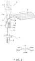
- FIG. 2 is a perspective view showing the general configuration of the bag-making and packaging unit 3.
- the six directions of “front (front-facing),” “rear (back-facing),” “up,” “down,” “left,” and “right” are defined as shown in FIG. 2 .
- the bag-making and packaging unit 3 is mainly configured from a forming mechanism 13, pull-down belt mechanisms 14, a longitudinal sealing mechanism 15, and a transverse sealing mechanism 17.
- the forming mechanism 13 forms into a cylindrical shape a sheet-like film F that is supplied from the film supply unit 4.
- the pull-down belt mechanisms 14 convey downward the film F that has been formed into the cylindrical shape.
- the longitudinal sealing mechanism 15 seals, in the longitudinal direction parallel to the conveyance direction, the overlapping portion of both end portions of the film F that has been formed into the cylindrical shape to thereby form a cylindrical film Fc.
- the transverse sealing mechanism 17 seals the cylindrical film Fc in the transverse direction orthogonal to the conveyance direction to thereby form bags B whose upper end portions and lower end portions have been transversely sealed.
- the forming mechanism 13 has a tube 13a and a former 13b.
- the tube 13b is an open cylinder-shaped member whose upper end and lower end are open. Contents C supplied from the combination weighing unit 2 are input to the opening in the upper end of the tube 13a.
- the former 13b is disposed surrounding the tube 13a.
- the film F that has been paid out from the film roll of the film supply unit 4 wraps around the tube 13a and is formed into the cylindrical shape when it passes through a gap between the tube 13a and the former 13b.
- the tube 13a and the former 13b can be replaced in accordance with the size of the bags B that are to be manufactured.
- the pull-down belt mechanisms 14 suck hold of and convey downward the film F wrapped around the tube 13a.
- the pull-down belt mechanisms 14 mainly have drive rollers 14a, follower rollers 14b, and a pair of belts 14c.
- the pair of belts 14c are disposed on both the right and left sides of the tube 13a so as to sandwich the tube 13a as shown in FIG. 2 and have mechanisms that suck hold of the film F that has been formed into the cylindrical shape.
- the pair of belts 14c are driven to rotate by the drive rollers 14a and the follower rollers 14b, whereby the pull-down belt mechanisms 14 convey downward the film F that has been formed into the cylindrical shape.
- the longitudinal sealing mechanism 15 seals in the longitudinal direction (the up and down direction in FIG. 2 ) the film F that has been formed into the cylindrical shape.
- the longitudinal sealing mechanism 15 is disposed on the front-facing side of the tube 13a.
- the longitudinal sealing mechanism 15 is moved by a drive mechanism (not shown in the drawings) in forward and rearward directions toward the tube 13a or away from the tube 13a.
- the longitudinal sealing mechanism 15 When the longitudinal sealing mechanism 15 is driven by the drive mechanism toward the tube 13a, the overlapping portion in the longitudinal direction of the film F wrapped around the tube 13a becomes sandwiched between the longitudinal sealing mechanism 15 and the tube 13a.
- the longitudinal sealing mechanism 15 heats the overlapping portion of the film F while pushing it with a fixed pressure against the tube 13a because of the drive mechanism to thereby heat-seal the overlapping portion of the film F in the longitudinal direction and form the cylindrical film Fc.
- the longitudinal sealing mechanism 15 has a heater that heats the overlapping portion of the film F and a heater belt that contacts the overlapping portion of the film F.
- the transverse sealing mechanism 17 seals the cylindrical film Fc in the transverse direction (the right and left direction in FIG. 2 ).
- the transverse sealing mechanism 17 is disposed under the forming mechanism 13, the pull-down belt mechanisms 14, and the longitudinal sealing mechanism 15.
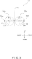
- FIG. 3 is a general side view of the transverse sealing mechanism 17 as seen from the right side of FIG. 2 .
- the transverse sealing mechanism 17 mainly has a first rotating body 50a and a second rotating body 50b.
- the first rotating body 50a is disposed on the front side of the cylindrical film Fc.
- the second rotating body 50b is disposed on the rear side of the cylindrical film Fc.
- the first rotating body 50a is positioned on the left side of the cylindrical film Fc
- the second rotating body 50b is positioned on the right side of the cylindrical film Fc.
- the first rotating body 50a mainly has a first rotating shaft 53a, a first sealing jaw 51a, and a second sealing jaw 52a.
- the second rotating body 50b mainly has a second rotating shaft 53b, a first sealing jaw 51b, and a second sealing jaw 52b.
- the first rotating body 50a when seen along the right and left direction, rotates about a rotational center C1 of the first rotating shaft 53a using the first rotating shaft 53a as a rotational axis.
- the second rotating body 50b when seen along the right and left direction, rotates about a rotational center C2 of the second rotating shaft 53b using the second rotating shaft 53b as a rotational axis.
- the transverse sealing mechanism 17 sandwiches, with the pair of first sealing jaws 51a, 51b or the pair of second sealing jaws 52a, 52b and along the transverse direction (the right and left direction in FIG. 2 ) intersecting the conveyance direction of the cylindrical film Fc, the cylindrical film Fc that is conveyed downward.
- the pair of first sealing jaws 51a, 51b or the pair of second sealing jaws 52a, 52b heat-seal the cylindrical film Fc in the transverse direction by sandwiching and heating the cylindrical film Fc.
- FIG. 4 is a side view showing the general configuration of the film supply unit 4.
- the sheet-like film F is conveyed from the right side (upstream side) to the left side (downstream side).
- the film supply unit 4 pays out the film F from a film roll FR, prints predetermined information on the top surface of the film F while conveying the film F, and supplies the film F to the forming mechanism 13 of the bag-making and packaging unit 3.
- the film supply unit 4 mainly has an air shaft 21, plural tension rollers 22, a printing device 23, an inspection device 24, a former roller 25, and a film position correction mechanism 26.
- the air shaft 21 is a shaft on which is set the film roll FR into which the sheet-like film F is wound.
- the air shaft 21 vacuum-sucks hold of and anchors the film roll FR.
- the air shaft 21 is driven to rotate by a shaft drive motor (not shown in the drawings). When the shaft drive motor rotates the air shaft 21, the sheet-like film F wound into the film roll FR is paid out.
- the film F paid out from the film roll FR in the film supply unit 4 is finally delivered to the bag-making and packaging unit 3.
- the film F is formed into the cylindrical shape by the forming mechanism 13 and is conveyed downward by the pull-down belt mechanisms 14. Because of this, in the film supply unit 4, the film F that has been paid out from the film roll FR is conveyed just the amount it has been paid out.
- the control device 7 can adjust the conveyance speed of the film F paid out from the film roll FR by controlling the shaft drive motor to change the rotational speed of the air shaft 21.
- the tension rollers 22 are rollers disposed in predetermined positions at predetermined distance intervals.
- the tension rollers 22 guide the film F to the printing device 23 while bending the film F paid out from the film roll FR and changing its conveyance angle.
- the tension rollers 22 apply moderate tension to the film F that is paid out from the film roll FR and conveyed and prevent slackness and meandering of the film F that is conveyed.
- the number and positions of the tension rollers 22 are arbitrarily settable in accordance with the position of the film roll FR and the dimensions of the film F.
- At least some of the tension rollers 22 are movable in the up and down direction. By moving the tension rollers 22 in the up and down direction, the tension that acts on the film F guided by the tension rollers 22 can be adjusted.
- the control device 7 detects the state of tension in the film F on the basis of the amount of displacement of the tension rollers 22 in the up and down direction. Additionally, on the basis of the detected state of tension, the control device 7 controls the shaft drive motor to adjust the conveyance speed of the film F so that the tension that acts on the film F falls within a predetermined range.
- the printing device 23 is disposed on the upstream side of the tension rollers 22.
- the printing device 23 mainly has a print head 23a and a print roller 23b.
- the print head 23a prints predetermined printing information on the top surface of the film F that is being conveyed.
- the printing information is printed in a predetermined printing region on the top surface of the film F.
- the printing information is the date of manufacture and the expiration date of the contents C in a case where, for example, the contents C are food products.
- the printing information is sent from the control device 7 to the printing device 23.
- the print head 23a is movable so as to be pressed against the film F and moved away from the film F. However, the print head 23a is not movable along the conveyance direction of the film F.
- the print roller 23b is a roller disposed opposing the print head 23a.
- the film F that is conveyed passes between the print head 23a and the print roller 23b.
- the print roller 23b finely adjusts the position of the film F so that the print head 23a opposes the top surface of the film F. Because of this, the print head 23a can print the printing information so that it fits in the printing region of the film F that is conveyed.
- the position of the print head 32a is manually adjustable in the width direction of the film F.
- the position of the print roller 23b is manually adjustable in the up and down direction.
- the inspection device 24 is installed in the neighborhood of the downstream side of the printing device 23.
- the inspection device 24 inspects whether or not the printing information has been accurately printed in the printing region of the film F.
- the inspection device 24 is a photosensor configured from a light-emitting element and a light-receiving element.
- the film F that is conveyed passes between the light-emitting element and the light-receiving element.
- the light-emitting element emits light to the printing region of the film F.
- the light-receiving element detects the light reflected by the printing region and detects the position of the printing information printed in the printing region.
- the inspection device 24 may also be an optical camera. In this case, the inspection device 24 inspects whether or not the printing information has been accurately printed in the printing region by capturing an image of the printing region of the film F that is conveyed and analyzing the acquired image.
- the former roller 25 is a roller disposed in the closest position to the former 13b.
- the former roller 25 is a roller for guiding in a predetermined direction the film F that is conveyed in the film supply unit 4.
- the former roller 25 has the role of regulating the final conveyance angle of the film F supplied to the former 13b to inhibit misalignment and sagging of the film F on the former 13b.
- the film supply unit 4 shown in FIG. 4 has one former roller 25.
- the number and position of the former roller 25 are arbitrarily settable in accordance with the configuration of the film supply unit 4.
- the position of the former roller 25 is manually adjustable.
- the film position adjustment mechanism 26 is disposed between the tension rollers 23 and the former roller 25.
- the film position adjustment mechanism 26 detects positional misalignment in the width direction of the film F that is being conveyed in the film supply unit 4 and, in a case where positional misalignment is occurring, automatically adjusts the width direction position of the film F.
- the film position adjustment mechanism 26 mainly has a film position sensor 26a, a first position adjustment roller 26b, and a second position adjustment roller 26c.
- the film position sensor 26a detects positional misalignment in the width direction of the film F.
- FIG. 5 is a drawing for describing the mechanism by which the film position sensor 26a detects positional misalignment.
- FIG. 5 is a drawing in which the film position sensor 26a is seen along the conveyance direction of the film F.
- the film position sensor 26a has a first light-emitting element 26d1, a second light-emitting element 26d2, a first light-receiving element 26e1, and a second light-receiving element 26e2.
- the first light-receiving element 26e1 is installed in a position where it can detect the light emitted from the first light-emitting element 26d1 in a case where the film F is not present between the first light-emitting element 26d1 and the first light-receiving element 26e1.
- the second light-receiving element 26e2 is installed in a position where it can detect the light emitted from the second light-emitting element 26d2 in a case where the film F is not present between the second light-emitting element 26d2 and the second light-receiving element 26e2.
- the film position sensor 26a is installed in a position where the film F is present between the first light-emitting element 26d1 and the first light-receiving element 26e1 and where the film F is not present between the second light-emitting element 26d2 and the second light-receiving element 26e2.
- the first light-receiving element 26e1 cannot detect the light emitted from the first light-emitting element 26d1
- the second light-receiving element 26e2 can detect the light emitted from the second light-emitting element 26d2.
- the first and second light-receiving elements 26e1, 26e2 can detect the light emitted from the first and second light-emitting elements 26d1, 26d2.
- the first and second light-receiving elements 26e1, 26e2 cannot detect the light emitted from the first and second light-emitting elements 26d1, 26d2. Because of this, the control device 7 can detect positional misalignment in the width direction of the film F on the basis of the detection signal of the film position sensor 26a.
- the position of the film position sensor 26a is manually adjustable in the width direction of the film F.
- the first position adjustment roller 26b and the second position adjustment roller 26c are a pair of rolls supported by a parallelogram link 26f.
- the control device 7 changes the shape of the link 26f to thereby adjust the positions of the first position adjustment roller 26b and the second position adjustment roller 26c on the basis of the detection signal of the film position sensor 26a. Because of this, the control device 7 can finely adjust the width direction position of the film F.
- FIG. 6(a) and FIG. 6(b) are drawings for describing how the width direction position of the film F differs in accordance with the shape of the link 26f.
- FIG. 6(a) and FIG. 6(b) are top views of the film F that is conveyed. In the state shown in FIG.
- the first and second light-receiving elements 26e1, 26e2 of the film position sensor 26a can detect the light emitted from the first and second light-emitting elements 26d1, 26d2, so positional misalignment in the width direction of the film F is occurring.
- the first light-receiving 26e1 cannot detect the light emitted from the first light-emitting element 26d1
- the second light-receiving element 26e2 can detect the light emitted from the second light-emitting element 26d2, so positional misalignment in the width direction of the film F is not occurring.
- control device 7 When the control device 7 detects positional misalignment in the width direction of the film F in the state shown in FIG. 6(a) , it changes the shape of the link 26f to thereby finely adjust the width direction position of the film F to the state shown in FIG. 6(b) . Specifically, the control device 7 changes the shape of the link 26f so that the second position adjustment roller 26c moves slightly rightward.
- the control device 7 has a notification function of notifying the user of the bag-making and packaging machine 1 of mechanisms requiring manual adjustment when switching a setting relating to the packaging of the contents C.
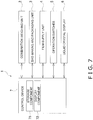
- FIG. 7 is a block diagram of the bag-making and packaging machine 1.
- the control device 7 mainly has a storage component 71 and a display component 72.
- the storage component 71 and the display component 72 are programs stored in the control device 7 and executed by the control device 7.
- the storage component 71 and the display component 72 realize the notification function of the control device 7.
- the storage component 71 stores settings (packaging settings) relating to the packaging of the contents C.
- the packaging settings are, for example, packaging capacity and bag dimensions.
- the packaging capacity is the number of bags B in which the contents C have been packaged that the bag-making and packaging machine 1 can manufacture in one minute.
- the bag dimensions are, for example, the width and length of the bags B in which the contents C become packaged.
- the storage component 71 stores packaging settings appropriate for each type of the contents C. In this case, it is necessary to switch the packaging setting when changing the contents C that are targets to be packaged by the bag-making and packaging machine 1.
- the storage component 71 may also store more than one different packaging setting with respect to the same type of the contents C. For example, in a case where there is more than one type of bag B for packaging the contents C, it is necessary to switch the packaging setting when switching the film F serving as the material of the bags B.
- the display component 72 displays on the liquid crystal display 6 a switching screen for switching the packaging setting.
- FIG. 8 is an example of the switching screen displayed on the liquid crystal display 6.
- the switching screen of FIG. 8 is configured from a current setting area A1, a reservation list area A2, and an input area A3.
- a database DB including four packaging settings stored in the storage component 71 is displayed in the reservation list area A2 of the switching screen.
- the database DB retains each of the four packaging settings as records R1 to R4.
- Each of the records R1 to R4 retains "reservation number,” “date and time,” “product name,” “capacity,” “bag width,” and “bag length” keys.
- the “reservation number” key is the main key of the records R1 to R4.
- the “date and time” key is the time when the records R1 to R4 were created or updated.
- the "product name” key is a character string specifically indicating the contents C.
- the “capacity” key is the number of bags B manufactured per minute (bpm; bags per minute).
- the "bag width” key is the width (mm) of the bags B and the width (mm) of the film F.
- the “bag length” key is the length (mm) of the bags B.
- the current packaging setting is displayed in the current setting area A1 of the switching screen.
- record 1 whose "reservation number" key value is 4, is displayed as the current packaging setting.
- FIG. 8 various buttons that the user can touch are displayed in the input area A3 of the switching screen.
- a "Switch” button 72a is displayed.
- the "Switch” button 72a is invalid (displayed with hatching) as shown in FIG. 8 in a case where none of the packaging settings being displayed in the reservation list area A2 has been selected.
- the packaging setting that has been touched is selected and the "Switch” button 72a becomes valid as shown in FIG. 9.
- FIG. 9 is an example of the switching screen in a state in which the "Switch" button 72a is valid.
- FIG. 9 is an example of the switching screen in a state in which the "Switch" button 72a is valid.
- the packaging setting of record R3, whose "reservation number" key value is 1, is selected.
- the record R3 that has been selected is displayed on the liquid crystal display 6 in a manner different from the other records.
- the control device 7 performs a switching process that switches the current packaging setting from the record R1 to the record R3.
- the display component 72 displays on the liquid crystal display 6 information relating to adjustment-requiring parts of the bag-making and packaging machine 1.
- the adjustment-requiring parts are parts or mechanisms that the user of the bag-making and packaging machine 1 needs to manually adjust when switching the packaging setting.
- the display component 72 displays on the liquid crystal display 6 information relating to the adjustment-requiring parts.
- FIG. 10 is an example of the switching screen in which the information relating to the adjustment-requiring parts is displayed.
- the adjustment-requiring parts of the bag-making and packaging machine 1 are "Position of Former Roller,” “Printing Right/Left Position,” “Printing Up/Down Position,” and “Film Position Sensor Position.”
- an icon S1, a character string S2, and an adjustment amount S3 are displayed for each adjustment-requiring part under the message “Check the following numerical values.”
- the icons S1 and the character strings S2 represent the adjustment-requiring parts.
- the adjustment amounts S3 are setting values after adjusting the adjustment-requiring parts.
- the adjustment amounts S3 are, for example, distances (mm) from reference positions.
- the adjustment amount S3 of "Position of Former Roller” is displayed as "40.” This means that the user needs to adjust the position of the former roller to 40 in the process of switching the packaging setting.
- "Position of Former Roller” is the position of the former roller 25 in the conveyance direction of the film F. In a case where it is necessary to replace the former 13b as a result of switching the packaging setting, it is necessary to change the position of the former roller 25 to match the new former 13b.
- "Printing Right/Left Position” is the position of the print head 23a of the printing device 23 in the width direction of the film F.
- "Printing Up/Down Position” is the up and down direction position of the print roller 23b of the printing device 23.
- “Printing Right/Left Position” and “Printing Up/Down Position” are the position of the printing information that is printed on the film F that is conveyed.
- "Film Position Sensor Position” is the position of the film position sensor 26a in the width direction of the film F.
- FIG. 11 is an example of the switching screen displayed on the liquid crystal display 6 after the action of switching the packaging setting has been completed.
- the record R3, whose "reservation number" key value is 1, is displayed in the current setting area A1 of the switching screen as the current packaging setting.
- the film F that has been supplied from the film supply unit 4 to the bag-making and packaging unit 3 is wrapped around the tube 13a and formed into a cylindrical shape, and is conveyed downward by the pull-down belt mechanisms 14. Both end portions-extending in the up and down direction-of the cylindrical film F wrapped around the tube 13a are overlapped on top of each other. The overlapping portion of the film F that has been formed into the cylindrical shape is sealed in the longitudinal direction by the longitudinal sealing mechanism 15, whereby the cylindrical film Fc is formed.
- the cylindrical film Fc that has been longitudinally sealed comes off the tube 13a and is conveyed downward to the transverse sealing mechanism 17.
- the transverse sealing mechanism 17 uses the pair of first sealing jaws 51a, 51b or the pair of second sealing jaws 52a, 52b to sandwich the cylindrical film Fc and transversely seal it.
- the bag B in which the contents C have been sealed is formed.
- the contents C that have been weighed by the combination weighing unit 2 drop through the inside of the tube 13a and are input to the cylindrical film Fc.
- the transversely sealed portion of the cylindrical film Fc is cut in the transverse direction by a cutter (not shown in the drawings) built into the first sealing jaw 51a or the second sealing jaw 52a. Because of this, the bag B in which the contents C have been sealed is cut away from the subsequent cylindrical film Fc.
- the bags B in which the contents C have been sealed are continuously manufactured.
- the manufactured bags B are thereafter transferred by a belt conveyor (not shown in the drawings) or the like to devices such as a thickness checker and a weight checker.
- the bag-making and packaging machine 1 has the function of displaying on the liquid crystal display 6 as shown in FIG. 10 and notifying the user of the information relating to the adjustment-requiring parts that are parts requiring manual adjustment when switching the setting relating to the packaging of the contents C. Consequently, the bag-making and packaging machine 1 has the function of preventing the user from forgetting to adjust adjustment-requiring parts that are parts that need to be manually adjusted when switching a setting relating to the packaging of products.
- the bag-making and packaging machine 1 displays on the liquid crystal display 6 the new setting values (adjustment amounts) for the adjustment-requiring parts as the information relating to the adjustment-requiring parts when switching the setting relating to the packaging of the contents C. For that reason, the user performing the adjustment of the adjustment-requiring parts no longer needs a memo or the like in which the new setting values are written down, so the user can efficiently perform the work of switching the setting relating to the packaging of the contents C.
- the control device 7 of the bag-making and packaging machine 1 has the notification function of notifying the user of the information relating to the adjustment-requiring parts when switching the packaging setting.
- the control device 7 has the storage component 71 and the display component 72 that are programs for realizing the notification function.
- the control device 7 may also have programs, in addition to the storage component 71 and the display component 72, for realizing the notification function.
- FIG. 12 is a block diagram of the bag-making and packaging machine 1 of this example modification.
- the control device 7 mainly has the storage component 71, the display component 72, a setting value input component 73, an adjustment complete input component 74, and a display manner changing component 75. These are programs stored in the control device 7 and executed by the control device 7. It will be noted that in this example modification the control device 7 does not need to have all of the setting value input component 73, the adjustment complete input component 74, and the display manner changing component 75, and it suffices for the control device 7 to have at least one of these. Next, the functions of each of the setting value input component 73, the adjustment complete input component 74, and the display manner changing component 75 will be described.
- the setting value input component 73 realizes a function for inputting adjustment amounts for the adjustment-requiring parts per packaging setting. For example, when registering (reserving) a new packaging setting, the user can input beforehand the adjustment amounts for the adjustment-requiring parts suitable for the registered packaging setting.
- FIG. 13 is a drawing for describing the function of the setting value input component 73.
- FIG. 13 is an example of an input screen for inputting adjustment amounts for the adjustment-requiring parts.
- the screen of FIG. 13 has substantially the same configuration as the screen of FIG. 10 .
- input boxes B1 to B4 for inputting the adjustment amounts are displayed.
- the default value in the input boxes B1 to B4 is "N/A," which indicates that an adjustment amount has not been input.
- numeric keys for inputting numerical values are displayed on the liquid crystal display 6.
- the user can operate the screen of FIG. 13 to input adjustment amounts for each of the adjustment-requiring parts and store them in the storage component 71.
- the user when the user switches to the newly registered packaging setting, the user can perform the work of adjusting the adjustment-requiring parts while checking the screen of FIG. 10 on which are displayed the adjustment amounts for each of the adjustment-requiring parts that the user input when registering that packaging setting. Consequently, the user of the bag-making and packaging machine 1 can, using the function of the setting value input component 73, make the appropriate adjustments without referring to a memo or the like even if the user forgets the setting values relating to the parts requiring manual adjustment.
- the adjustment complete input component 74 realizes a function for the user to inform the control device 7 that the user has completed the adjustment of the adjustment-requiring parts.
- FIG. 14 is a drawing for describing the function of the adjustment complete input component 74.
- FIG. 14 shows a screen displayed on the liquid crystal display 6 that is the same as the one in FIG. 10 . However, on the screen of FIG. 14 , a "Confirm" button 72c not displayed on the screen of FIG. 10 is displayed.
- the "Confirm” button 72c is a button that the user touches after the user has completed the work of manually adjusting the adjustment-requiring parts. By touching the "Confirm” button 72c, the user can relay to the control device 7 that the user has completed the work of adjusting the adjustment-requiring parts and can confirm the adjustment work.
- the control device 7 can start the process of packaging the contents C after the work of adjusting the adjustment-requiring parts by the user has been reliably completed. That is, the adjustment complete input component 74 can prevent the bag-making and packaging machine 1 from starting the process of packaging the contents C before the work of adjusting the adjustment-requiring parts that is necessary when switching the packaging setting is completed. It will be noted that instead of the "Confirm" button 72c displayed on the screen of the liquid crystal display 6, the user may also push a physical button of the operation switches 5 or the like to thereby relay to the control device 7 that the user has completed the work of adjusting the adjustment-requiring parts and confirm the adjustment work.
- the display manner changing component 75 realizes the function of displaying on the liquid crystal display 6, in a manner different from the adjustment-requiring parts for which manual adjustment has not been completed, the adjustment-requiring parts for which manual adjustment has been completed when switching the packaging setting.
- FIG. 15 is a drawing for describing the function of the display manner changing component 75.
- FIG. 15 shows a screen displayed on the liquid crystal display 6 that is the same as the one in FIG. 10 .
- check boxes 72d1 to 72d4 are displayed on the left side of the icons for each of the adjustment-requiring parts.
- the check box 72d1 is displayed on the left side of the icon for "Position of Former Roller.” Initially, all the check boxes 72d1 to 72d4 are unchecked.
- the control device 7 can distinguish between, and display on the liquid crystal display 6, the adjustment-requiring parts for which manual adjustment has been completed and the adjustment-requiring parts for which manual adjustment has not been completed. Consequently, the control device 7 can display, in a way that is easy to understand on the liquid crystal display 6, the state of progress of the adjustment work when switching the packaging setting, so the adjustment work of the user can be made efficient.
- control device 7 may also validate the "Confirm" button 72c only when all the check boxes 72d1 to 72d4 have been checked. In this case, the user cannot complete the work of adjusting the adjustment-requiring parts until the user checks all the check boxes 72d1 to 72d4.
- the display component 72 when switching the packaging setting, displays on the liquid crystal display 6 the information relating to the adjustment-requiring parts requiring manual adjustment in the bag-making and packaging machine 1.
- the display component 72 may also display, in a manner different from other of the adjustment-requiring parts, the adjustment-requiring parts for which the adjustment amounts differ between before the switch and after the switch.
- FIG. 16 is a drawing for describing the function of the display component 72 in this example modification.
- FIG. 16 shows an example of a screen displayed on the liquid crystal display 6 that is the same as the one in FIG. 10 .
- "Printing Right/Left Position” and “Printing Up/Down Position” are displayed in a manner different from “Position of Former Roller” and "Film Position Sensor Position.”
- "Printing Right/Left Position” and “Printing Up/Down Position” are not displayed.
- the display component 72 displays "Position of Former Roller” and "Film Position Sensor Position” on the liquid crystal display 6 in such a way that they are more conspicuous than "Printing Right/Left Position” and "Printing Up/Down Position.” For example, the display component 72 faintly displays, or does not display, "Printing Right/Left Position” and "Printing Up/Down Position.” In this way, the display component 72 can, by emphasizing and displaying on the liquid crystal display 6 only the adjustment-requiring parts that the user needs to manually adjust, notify the user of parts requiring manual adjustment in a way that is easy to understand.
- the bag-making and packaging machine 1 for packaging in the film F and bag packing the contents C such as food products was described as the product processing apparatus pertaining to the invention.
- the product processing apparatus pertaining to the invention may also be an apparatus other than the bag-making and packaging machine 1.
- the product processing apparatus pertaining to the invention may also be a box packing apparatus for packing, into cardboard boxes, bags in which food products have been packaged.
- the control device of the box packing apparatus has the function of displaying on the liquid crystal display 6 and notifying the user of information relating to adjustment-requiring parts that are parts requiring manual adjustment when switching a setting relating to the box packing. Consequently, the box packing apparatus of this example modification has the function of preventing the user from forgetting to adjust adjustment-requiring parts that are parts that need to be manually adjusted when switching a setting relating to the box packing.
- the product processing apparatus pertaining to the invention is useful because it has the function of preventing a user from forgetting to adjust parts that need to be manually adjusted when switching a setting.
- Patent Document 1 JP-ANo. 2006-36246
Landscapes
- Engineering & Computer Science (AREA)
- Mechanical Engineering (AREA)
- Human Computer Interaction (AREA)
- Manufacturing & Machinery (AREA)
- Physics & Mathematics (AREA)
- General Physics & Mathematics (AREA)
- Automation & Control Theory (AREA)
- Containers And Plastic Fillers For Packaging (AREA)
- Auxiliary Devices For And Details Of Packaging Control (AREA)
Abstract
Description
- The present invention relates to a product processing apparatus for packaging products in film or the like or box packing products into cardboard boxes or the like.
- Bag-making and packaging machines for packaging products in film or the like have mechanisms requiring manual adjustment when switching a setting relating to the packaging of the products. Examples of such mechanisms include a roller that guides the film paid out from a film roll and a printing device for printing predetermined information on the film that is being conveyed. For example, in the case of a bag-making and packaging machine having a printing device such as disclosed in patent document 1 (
JP-A No. 2006-36246 - However, the method of using a paper memo to make the adjustments carries with it the concern that if the worker loses the memo, rechecking the mechanisms that need to be manually adjusted will consume time, and also carries with it the concern that the memo will get inside the bag-making and packaging machine and cause problems. Furthermore, if the worker makes the adjustments without using a memo, the worker needs to rely on his/her own memory to adjust the mechanisms that need to be manually adjusted, so there is the concern a part that should be adjusted will escape the worker's memory. The above problems have the potential to occur even with a box packing apparatus for box packing products into cardboard boxes or the like.
- It is an object of the present invention to provide a product processing apparatus that has the function of preventing a user from forgetting to adjust a part that needs to be manually adjusted when switching a setting.
- A product processing apparatus pertaining to the invention is an apparatus that performs packaging or box packing of products, and has a storage component and a display component. The storage component stores settings relating to the packaging or the box packing of the products. The display component displays adjustment-requiring parts requiring adjustment in the apparatus when changing the settings relating to the packaging or the box packing of the products.
- This product processing apparatus has the function of displaying on a display or the like and notifying the user of information relating to parts requiring manual adjustment when switching the settings relating to the packaging or the box packing of the products. Consequently, this product processing apparatus has the function of preventing the user from forgetting to adjust a part that needs to be manually adjusted when switching the settings relating to the packaging or the box packing of the products.
- Furthermore, it is preferred that when changing the settings, the display component further display setting values for the adjustment-requiring parts after the change in the settings.
- In this case, when changing the settings relating to the packaging or the box packing of the products, new setting values for the parts requiring adjustment are displayed. Because of this, a memo or the like in which the new setting values are written down becomes unnecessary.
- Furthermore, it is preferred that the product processing apparatus further have a setting value input component for inputting the setting values per each of the settings.
- In this case, when registering (reserving) new settings relating to the packaging or the box packing of the products, by inputting beforehand the setting values for the parts requiring adjustment, the user can make the appropriate adjustments without referring to a memo or the like even if the user later forgets the setting values.
- Furthermore, it is preferred that when changing the settings, the display component display, in a manner different from other of the adjustment-requiring parts, the adjustment-requiring parts for which the setting values differ between before changing and after changing the settings.
- In this case, for example, by displaying only parts requiring a change in their setting values and not displaying the other parts or faintly displaying the parts not requiring a change in their setting values, the product processing apparatus can notify the user, in a way that is easy to understand, of the parts requiring a change in their setting values.
- Furthermore, it is preferred that the product processing apparatus further have an adjustment complete input component for inputting that adjustment of the adjustment-requiring parts has been completed.
- In this case, the user can relay to the apparatus that the user has completed the adjustment of the adjustment-requiring parts and confirm the adjustment work. For that reason, the product processing apparatus can start the packaging or the box packing of the products after the adjustment work by the user has reliably ended.
- Furthermore, it is preferred that the product processing apparatus further have a display manner changing component for causing the display component to display, in a manner different from the adjustment-requiring parts for which adjustment has not been completed, the adjustment-requiring parts for which adjustment has been completed when changing the settings.
- In this case, in a case where there is more than one part requiring adjustment, it can be made easier for the user to check, each time adjustment of a part is completed, that part and see the progress of the work.
- Furthermore, the product processing apparatus is an apparatus that packages the products in film, and has a conveyance unit, a roller, and a printing unit. The conveyance unit conveys the film in its longitudinal direction. The roller guides the film that is being conveyed. The printing unit prints predetermined information on the film that is being conveyed. The display component displays, as the adjustment-requiring parts, at least one of the position of the roller, the width direction position of the film that is being conveyed, and the position where the printing unit prints on the film.
- The product processing apparatus pertaining to the invention has the function of preventing a user from forgetting to adjust a part that needs to be manually adjusted when switching a setting relating to the packaging or the box packing of products.
-
-
FIG. 1 is a perspective view of a bag-making andpackaging machine 1 that is an embodiment of the invention. -
FIG. 2 is a perspective view showing the general configuration of a bag-making andpackaging unit 3. -
FIG. 3 is a general side view showing atransverse sealing mechanism 17 as seen from the right side ofFIG. 2 . -
FIG. 4 is a side view showing the general configuration of afilm supply unit 4. -
FIG. 5 is a drawing for describing the mechanism by which afilm position sensor 26a detects positional misalignment. -
FIG. 6(a) and FIG. 6(b) are drawings for describing how the width direction position of film F differs in accordance with the shape of alink 26f. In the state shown inFIG. 6(a) , positional misalignment in the width direction of the film F is occurring. In the state shown inFIG. 6(b) , positional misalignment in the width direction of the film F is not occurring. -
FIG. 7 is a block diagram of the bag-making andpackaging machine 1. -
FIG. 8 is an example of a switching screen displayed on aliquid crystal display 6. -
FIG. 9 is an example of the switching screen in a state where a "Switch"button 72a is valid. -
FIG. 10 is an example of the switching screen in which information relating to adjustment-requiring parts is displayed. -
FIG. 11 is an example of the switching screen displayed on theliquid crystal display 6 after switching a packaging setting. -
FIG. 12 is a block diagram of the bag-making andpackaging machine 1 in example modification A. -
FIG. 13 is a drawing for describing the function of a settingvalue input component 73 in example modification A. -
FIG. 14 is a drawing for describing the function of an adjustmentcomplete input component 74 in example modification A. -
FIG. 15 is a drawing for describing the function of a displaymanner changing component 75 in example modification A. -
FIG. 16 is a drawing for describing the function of adisplay component 72 in example modification B. - An embodiment of the invention will be described with reference to the drawings. The embodiment described below is a specific example of the invention and is not intended to limit the technical scope of the invention.
- A product processing apparatus pertaining to the invention is an apparatus that performs packaging or box packing of products. In this embodiment, a bag-making and packaging machine for packaging in film and bag packing contents such as food products will be described as the product processing apparatus.
-
FIG. 1 is a perspective view of a bag-making andpackaging machine 1 that is an embodiment of the invention. The bag-making andpackaging machine 1 is mainly configured from acombination weighing unit 2, a bag-making andpackaging unit 3, afilm supply unit 4,operation switches 5, aliquid crystal display 6, and acontrol device 7. - The
combination weighing unit 2 is disposed above the bag-making andpackaging unit 3. Thecombination weighing unit 2 weighs, with plural weighing hoppers, the weights of contents and combines the values of the weights that have been weighed by each weighing hopper so as to reach a predetermined total weight. Thecombination weighing unit 2 discharges downward and supplies to the bag-making andpackaging unit 3 the contents having the combined predetermined total weight. - The bag-making and
packaging unit 3 seals in bags and packages the contents in accordance with the timing when the contents are supplied from thecombination weighing unit 2. The detailed configuration and actions of the bag-making andpackaging unit 3 will be described later. - The
film supply unit 4 is installed adjacent to the bag-making andpackaging unit 3 and supplies to the bag-making and packaging unit 3 a film that becomes formed into the bags. A film roll into which the film is wound is set in thefilm supply unit 4. Thefilm supply unit 4 pays out the film from the film roll. The detailed configuration and actions of thefilm supply unit 4 will be described later. - The operation switches 5 and the
liquid crystal display 6 are attached to the front of the bag-making andpackaging machine 1 body. Theliquid crystal display 6 is a touch panel display disposed in a position where the operator of the operation switches 5 can see it. The operation switches 5 and theliquid crystal display 6 function as input devices that receive instructions with respect to the bag-making andpackaging machine 1 and settings relating to the bag-making andpackaging machine 1. Theliquid crystal display 6 functions as an output device that displays information relating to the bag-making andpackaging machine 1. - The
control device 7 is mainly configured from a CPU, a ROM, a RAM, and an HDD (hard disk drive). It will be noted that an SSD (solid state drive) may also be used instead of an HDD. Thecontrol device 7 also has a display control circuit, an input circuit, and communication ports not shown in the drawings. The display control circuit is a circuit that controls the display of theliquid crystal display 6. The input circuit is a circuit that imports input data that have been input by the operator via the touch panel of theliquid crystal display 6 and the operation switches 5. The communication ports are ports that enable connection to external devices such as a printer and a network such as a LAN. - The
control device 7 is connected to thecombination weighing unit 2, the bag-making andpackaging unit 3, thefilm supply unit 4, the operation switches 5, and theliquid crystal display 6. Thecontrol device 7 controls thecombination weighing unit 2, the bag-making andpackaging unit 3, and thefilm supply unit 4, and outputs various types of information to theliquid crystal display 6, on the basis of input from the operation switches 5 and theliquid crystal display 6. The detailed configuration and actions of thecontrol device 7 will be described later. -
FIG. 2 is a perspective view showing the general configuration of the bag-making andpackaging unit 3. In the following description, the six directions of "front (front-facing)," "rear (back-facing)," "up," "down," "left," and "right" are defined as shown inFIG. 2 . - The bag-making and
packaging unit 3 is mainly configured from a formingmechanism 13, pull-downbelt mechanisms 14, alongitudinal sealing mechanism 15, and atransverse sealing mechanism 17. The formingmechanism 13 forms into a cylindrical shape a sheet-like film F that is supplied from thefilm supply unit 4. The pull-downbelt mechanisms 14 convey downward the film F that has been formed into the cylindrical shape. Thelongitudinal sealing mechanism 15 seals, in the longitudinal direction parallel to the conveyance direction, the overlapping portion of both end portions of the film F that has been formed into the cylindrical shape to thereby form a cylindrical film Fc. Thetransverse sealing mechanism 17 seals the cylindrical film Fc in the transverse direction orthogonal to the conveyance direction to thereby form bags B whose upper end portions and lower end portions have been transversely sealed. - The forming
mechanism 13 has atube 13a and a former 13b. Thetube 13b is an open cylinder-shaped member whose upper end and lower end are open. Contents C supplied from thecombination weighing unit 2 are input to the opening in the upper end of thetube 13a. The former 13b is disposed surrounding thetube 13a. The film F that has been paid out from the film roll of thefilm supply unit 4 wraps around thetube 13a and is formed into the cylindrical shape when it passes through a gap between thetube 13a and the former 13b. Thetube 13a and the former 13b can be replaced in accordance with the size of the bags B that are to be manufactured. - The pull-down
belt mechanisms 14 suck hold of and convey downward the film F wrapped around thetube 13a. The pull-downbelt mechanisms 14 mainly havedrive rollers 14a,follower rollers 14b, and a pair ofbelts 14c. The pair ofbelts 14c are disposed on both the right and left sides of thetube 13a so as to sandwich thetube 13a as shown inFIG. 2 and have mechanisms that suck hold of the film F that has been formed into the cylindrical shape. The pair ofbelts 14c are driven to rotate by thedrive rollers 14a and thefollower rollers 14b, whereby the pull-downbelt mechanisms 14 convey downward the film F that has been formed into the cylindrical shape. - The
longitudinal sealing mechanism 15 seals in the longitudinal direction (the up and down direction inFIG. 2 ) the film F that has been formed into the cylindrical shape. Thelongitudinal sealing mechanism 15 is disposed on the front-facing side of thetube 13a. Thelongitudinal sealing mechanism 15 is moved by a drive mechanism (not shown in the drawings) in forward and rearward directions toward thetube 13a or away from thetube 13a. - When the
longitudinal sealing mechanism 15 is driven by the drive mechanism toward thetube 13a, the overlapping portion in the longitudinal direction of the film F wrapped around thetube 13a becomes sandwiched between thelongitudinal sealing mechanism 15 and thetube 13a. Thelongitudinal sealing mechanism 15 heats the overlapping portion of the film F while pushing it with a fixed pressure against thetube 13a because of the drive mechanism to thereby heat-seal the overlapping portion of the film F in the longitudinal direction and form the cylindrical film Fc. Thelongitudinal sealing mechanism 15 has a heater that heats the overlapping portion of the film F and a heater belt that contacts the overlapping portion of the film F. - The
transverse sealing mechanism 17 seals the cylindrical film Fc in the transverse direction (the right and left direction inFIG. 2 ). Thetransverse sealing mechanism 17 is disposed under the formingmechanism 13, the pull-downbelt mechanisms 14, and thelongitudinal sealing mechanism 15. -
FIG. 3 is a general side view of thetransverse sealing mechanism 17 as seen from the right side ofFIG. 2 . InFIG. 3 , the direction perpendicular to the page is the right and left direction inFIG. 2 . Thetransverse sealing mechanism 17 mainly has a firstrotating body 50a and a secondrotating body 50b. The firstrotating body 50a is disposed on the front side of the cylindrical film Fc. The secondrotating body 50b is disposed on the rear side of the cylindrical film Fc. Within the page ofFIG. 3 , the firstrotating body 50a is positioned on the left side of the cylindrical film Fc, and the secondrotating body 50b is positioned on the right side of the cylindrical film Fc. - The first
rotating body 50a mainly has a firstrotating shaft 53a, afirst sealing jaw 51a, and asecond sealing jaw 52a. The secondrotating body 50b mainly has a secondrotating shaft 53b, afirst sealing jaw 51b, and asecond sealing jaw 52b. The firstrotating body 50a, when seen along the right and left direction, rotates about a rotational center C1 of the firstrotating shaft 53a using the firstrotating shaft 53a as a rotational axis. The secondrotating body 50b, when seen along the right and left direction, rotates about a rotational center C2 of the secondrotating shaft 53b using the secondrotating shaft 53b as a rotational axis. When thetransverse sealing mechanism 17 is seen along the right and left direction, the pair offirst sealing jaws second sealing jaws FIG. 3 , the paths traced by the pair offirst sealing jaws second sealing jaws - The
transverse sealing mechanism 17 sandwiches, with the pair offirst sealing jaws second sealing jaws FIG. 2 ) intersecting the conveyance direction of the cylindrical film Fc, the cylindrical film Fc that is conveyed downward. The pair offirst sealing jaws second sealing jaws -
FIG. 4 is a side view showing the general configuration of thefilm supply unit 4. Within the page ofFIG. 4 , the sheet-like film F is conveyed from the right side (upstream side) to the left side (downstream side). Thefilm supply unit 4 pays out the film F from a film roll FR, prints predetermined information on the top surface of the film F while conveying the film F, and supplies the film F to the formingmechanism 13 of the bag-making andpackaging unit 3. Thefilm supply unit 4 mainly has anair shaft 21,plural tension rollers 22, aprinting device 23, aninspection device 24, aformer roller 25, and a filmposition correction mechanism 26. - The
air shaft 21 is a shaft on which is set the film roll FR into which the sheet-like film F is wound. Theair shaft 21 vacuum-sucks hold of and anchors the film roll FR. Theair shaft 21 is driven to rotate by a shaft drive motor (not shown in the drawings). When the shaft drive motor rotates theair shaft 21, the sheet-like film F wound into the film roll FR is paid out. - The film F paid out from the film roll FR in the
film supply unit 4 is finally delivered to the bag-making andpackaging unit 3. In the bag-making andpackaging unit 3, the film F is formed into the cylindrical shape by the formingmechanism 13 and is conveyed downward by the pull-downbelt mechanisms 14. Because of this, in thefilm supply unit 4, the film F that has been paid out from the film roll FR is conveyed just the amount it has been paid out. Thecontrol device 7 can adjust the conveyance speed of the film F paid out from the film roll FR by controlling the shaft drive motor to change the rotational speed of theair shaft 21. - The
tension rollers 22 are rollers disposed in predetermined positions at predetermined distance intervals. Thetension rollers 22 guide the film F to theprinting device 23 while bending the film F paid out from the film roll FR and changing its conveyance angle. Thetension rollers 22 apply moderate tension to the film F that is paid out from the film roll FR and conveyed and prevent slackness and meandering of the film F that is conveyed. The number and positions of thetension rollers 22 are arbitrarily settable in accordance with the position of the film roll FR and the dimensions of the film F. - At least some of the
tension rollers 22 are movable in the up and down direction. By moving thetension rollers 22 in the up and down direction, the tension that acts on the film F guided by thetension rollers 22 can be adjusted. In this case, thecontrol device 7 detects the state of tension in the film F on the basis of the amount of displacement of thetension rollers 22 in the up and down direction. Additionally, on the basis of the detected state of tension, thecontrol device 7 controls the shaft drive motor to adjust the conveyance speed of the film F so that the tension that acts on the film F falls within a predetermined range. - The
printing device 23 is disposed on the upstream side of thetension rollers 22. Theprinting device 23 mainly has aprint head 23a and aprint roller 23b. Theprint head 23a prints predetermined printing information on the top surface of the film F that is being conveyed. The printing information is printed in a predetermined printing region on the top surface of the film F. The printing information is the date of manufacture and the expiration date of the contents C in a case where, for example, the contents C are food products. The printing information is sent from thecontrol device 7 to theprinting device 23. Theprint head 23a is movable so as to be pressed against the film F and moved away from the film F. However, theprint head 23a is not movable along the conveyance direction of the film F. - The
print roller 23b is a roller disposed opposing theprint head 23a. The film F that is conveyed passes between theprint head 23a and theprint roller 23b. Theprint roller 23b finely adjusts the position of the film F so that theprint head 23a opposes the top surface of the film F. Because of this, theprint head 23a can print the printing information so that it fits in the printing region of the film F that is conveyed. The position of the print head 32a is manually adjustable in the width direction of the film F. The position of theprint roller 23b is manually adjustable in the up and down direction. - The
inspection device 24 is installed in the neighborhood of the downstream side of theprinting device 23. Theinspection device 24 inspects whether or not the printing information has been accurately printed in the printing region of the film F. Theinspection device 24 is a photosensor configured from a light-emitting element and a light-receiving element. The film F that is conveyed passes between the light-emitting element and the light-receiving element. The light-emitting element emits light to the printing region of the film F. The light-receiving element detects the light reflected by the printing region and detects the position of the printing information printed in the printing region. - It will be noted that the
inspection device 24 may also be an optical camera. In this case, theinspection device 24 inspects whether or not the printing information has been accurately printed in the printing region by capturing an image of the printing region of the film F that is conveyed and analyzing the acquired image. - The
former roller 25 is a roller disposed in the closest position to the former 13b. Theformer roller 25 is a roller for guiding in a predetermined direction the film F that is conveyed in thefilm supply unit 4. Specifically, theformer roller 25 has the role of regulating the final conveyance angle of the film F supplied to the former 13b to inhibit misalignment and sagging of the film F on the former 13b. - The
film supply unit 4 shown inFIG. 4 has oneformer roller 25. The number and position of theformer roller 25 are arbitrarily settable in accordance with the configuration of thefilm supply unit 4. The position of theformer roller 25 is manually adjustable. - The film
position adjustment mechanism 26 is disposed between thetension rollers 23 and theformer roller 25. The filmposition adjustment mechanism 26 detects positional misalignment in the width direction of the film F that is being conveyed in thefilm supply unit 4 and, in a case where positional misalignment is occurring, automatically adjusts the width direction position of the film F. The filmposition adjustment mechanism 26 mainly has afilm position sensor 26a, a firstposition adjustment roller 26b, and a secondposition adjustment roller 26c. - The
film position sensor 26a detects positional misalignment in the width direction of the film F.FIG. 5 is a drawing for describing the mechanism by which thefilm position sensor 26a detects positional misalignment.FIG. 5 is a drawing in which thefilm position sensor 26a is seen along the conveyance direction of the film F. Thefilm position sensor 26a has a first light-emitting element 26d1, a second light-emitting element 26d2, a first light-receiving element 26e1, and a second light-receiving element 26e2. The first light-receiving element 26e1 is installed in a position where it can detect the light emitted from the first light-emitting element 26d1 in a case where the film F is not present between the first light-emitting element 26d1 and the first light-receiving element 26e1. The second light-receiving element 26e2 is installed in a position where it can detect the light emitted from the second light-emitting element 26d2 in a case where the film F is not present between the second light-emitting element 26d2 and the second light-receiving element 26e2. - In a case where there is no positional misalignment in the width direction of the film F, as shown in
FIG. 5 , thefilm position sensor 26a is installed in a position where the film F is present between the first light-emitting element 26d1 and the first light-receiving element 26e1 and where the film F is not present between the second light-emitting element 26d2 and the second light-receiving element 26e2. In this case, the first light-receiving element 26e1 cannot detect the light emitted from the first light-emitting element 26d1, and the second light-receiving element 26e2 can detect the light emitted from the second light-emitting element 26d2. - In a case where there is positional misalignment in the width direction of the film F, the first and second light-receiving elements 26e1, 26e2 can detect the light emitted from the first and second light-emitting elements 26d1, 26d2. Alternatively, in a case where there is positional misalignment in the width direction of the film F, the first and second light-receiving elements 26e1, 26e2 cannot detect the light emitted from the first and second light-emitting elements 26d1, 26d2. Because of this, the
control device 7 can detect positional misalignment in the width direction of the film F on the basis of the detection signal of thefilm position sensor 26a. The position of thefilm position sensor 26a is manually adjustable in the width direction of the film F. - The first
position adjustment roller 26b and the secondposition adjustment roller 26c are a pair of rolls supported by aparallelogram link 26f. Thecontrol device 7 changes the shape of thelink 26f to thereby adjust the positions of the firstposition adjustment roller 26b and the secondposition adjustment roller 26c on the basis of the detection signal of thefilm position sensor 26a. Because of this, thecontrol device 7 can finely adjust the width direction position of the film F.FIG. 6(a) and FIG. 6(b) are drawings for describing how the width direction position of the film F differs in accordance with the shape of thelink 26f.FIG. 6(a) and FIG. 6(b) are top views of the film F that is conveyed. In the state shown inFIG. 6(a) , the first and second light-receiving elements 26e1, 26e2 of thefilm position sensor 26a can detect the light emitted from the first and second light-emitting elements 26d1, 26d2, so positional misalignment in the width direction of the film F is occurring. In the state shown inFIG. 6(b) , the first light-receiving 26e1 cannot detect the light emitted from the first light-emitting element 26d1, but the second light-receiving element 26e2 can detect the light emitted from the second light-emitting element 26d2, so positional misalignment in the width direction of the film F is not occurring. When thecontrol device 7 detects positional misalignment in the width direction of the film F in the state shown inFIG. 6(a) , it changes the shape of thelink 26f to thereby finely adjust the width direction position of the film F to the state shown inFIG. 6(b) . Specifically, thecontrol device 7 changes the shape of thelink 26f so that the secondposition adjustment roller 26c moves slightly rightward. - The
control device 7 has a notification function of notifying the user of the bag-making andpackaging machine 1 of mechanisms requiring manual adjustment when switching a setting relating to the packaging of the contents C.FIG. 7 is a block diagram of the bag-making andpackaging machine 1. Thecontrol device 7 mainly has astorage component 71 and adisplay component 72. Thestorage component 71 and thedisplay component 72 are programs stored in thecontrol device 7 and executed by thecontrol device 7. Thestorage component 71 and thedisplay component 72 realize the notification function of thecontrol device 7. - The
storage component 71 stores settings (packaging settings) relating to the packaging of the contents C. The packaging settings are, for example, packaging capacity and bag dimensions. The packaging capacity is the number of bags B in which the contents C have been packaged that the bag-making andpackaging machine 1 can manufacture in one minute. The bag dimensions are, for example, the width and length of the bags B in which the contents C become packaged. Usually the packaging capacity and the bag dimensions differ depending on the type of the contents C, so thestorage component 71 stores packaging settings appropriate for each type of the contents C. In this case, it is necessary to switch the packaging setting when changing the contents C that are targets to be packaged by the bag-making andpackaging machine 1. Furthermore, thestorage component 71 may also store more than one different packaging setting with respect to the same type of the contents C. For example, in a case where there is more than one type of bag B for packaging the contents C, it is necessary to switch the packaging setting when switching the film F serving as the material of the bags B. - The
display component 72 displays on the liquid crystal display 6 a switching screen for switching the packaging setting.FIG. 8 is an example of the switching screen displayed on theliquid crystal display 6. The switching screen ofFIG. 8 is configured from a current setting area A1, a reservation list area A2, and an input area A3. - In
FIG. 8 , a database DB including four packaging settings stored in thestorage component 71 is displayed in the reservation list area A2 of the switching screen. The database DB retains each of the four packaging settings as records R1 to R4. Each of the records R1 to R4 retains "reservation number," "date and time," "product name," "capacity," "bag width," and "bag length" keys. The "reservation number" key is the main key of the records R1 to R4. The "date and time" key is the time when the records R1 to R4 were created or updated. The "product name" key is a character string specifically indicating the contents C. The "capacity" key is the number of bags B manufactured per minute (bpm; bags per minute). The "bag width" key is the width (mm) of the bags B and the width (mm) of the film F. The "bag length" key is the length (mm) of the bags B. - In
FIG 8 , the current packaging setting is displayed in the current setting area A1 of the switching screen. InFIG. 8 ,record 1, whose "reservation number" key value is 4, is displayed as the current packaging setting. - In
FIG. 8 , various buttons that the user can touch are displayed in the input area A3 of the switching screen. InFIG. 8 , a "Switch"button 72a is displayed. The "Switch"button 72a is invalid (displayed with hatching) as shown inFIG. 8 in a case where none of the packaging settings being displayed in the reservation list area A2 has been selected. However, when the user touches any one of the packaging settings being displayed in the reservation list area A2 in the state shown inFIG. 8 , the packaging setting that has been touched is selected and the "Switch"button 72a becomes valid as shown inFIG. 9. FIG. 9 is an example of the switching screen in a state in which the "Switch"button 72a is valid. InFIG. 9 , the packaging setting of record R3, whose "reservation number" key value is 1, is selected. As shown inFIG. 9 , the record R3 that has been selected is displayed on theliquid crystal display 6 in a manner different from the other records. When the user touches the "Switch"button 72a in the state shown inFIG. 9 , thecontrol device 7 performs a switching process that switches the current packaging setting from the record R1 to the record R3. - Furthermore, in the process of switching the packaging setting, the
display component 72 displays on theliquid crystal display 6 information relating to adjustment-requiring parts of the bag-making andpackaging machine 1. The adjustment-requiring parts are parts or mechanisms that the user of the bag-making andpackaging machine 1 needs to manually adjust when switching the packaging setting. Specifically, when the "Switch"button 72a is touched in the state shown inFIG. 9 , thedisplay component 72 displays on theliquid crystal display 6 information relating to the adjustment-requiring parts.FIG. 10 is an example of the switching screen in which the information relating to the adjustment-requiring parts is displayed. In this embodiment, the adjustment-requiring parts of the bag-making andpackaging machine 1 are "Position of Former Roller," "Printing Right/Left Position," "Printing Up/Down Position," and "Film Position Sensor Position." InFIG. 10 , an icon S1, a character string S2, and an adjustment amount S3 are displayed for each adjustment-requiring part under the message "Check the following numerical values." The icons S1 and the character strings S2 represent the adjustment-requiring parts. The adjustment amounts S3 are setting values after adjusting the adjustment-requiring parts. The adjustment amounts S3 are, for example, distances (mm) from reference positions. For example, inFIG. 10 , the adjustment amount S3 of "Position of Former Roller" is displayed as "40." This means that the user needs to adjust the position of the former roller to 40 in the process of switching the packaging setting. - Each of the adjustment-requiring parts shown in
FIG. 10 will be described. "Position of Former Roller" is the position of theformer roller 25 in the conveyance direction of the film F. In a case where it is necessary to replace the former 13b as a result of switching the packaging setting, it is necessary to change the position of theformer roller 25 to match the new former 13b. "Printing Right/Left Position" is the position of theprint head 23a of theprinting device 23 in the width direction of the film F. "Printing Up/Down Position" is the up and down direction position of theprint roller 23b of theprinting device 23. "Printing Right/Left Position" and "Printing Up/Down Position" are the position of the printing information that is printed on the film F that is conveyed. "Film Position Sensor Position" is the position of thefilm position sensor 26a in the width direction of the film F. - After the information relating to the adjustment-requiring parts is displayed on the
liquid crystal display 6 as shown inFIG. 10 , the user manually adjusts each of the adjustment-requiring parts in accordance with the information displayed inFIG. 10 . When the user touches an arbitrary place on the screen of theliquid crystal display 6 after having adjusted each of the adjustment-requiring parts, the information relating to the adjustment-requiring parts can be erased from the screen of theliquid crystal display 6. Because of this, the action of switching the packaging setting by the user is completed.FIG. 11 is an example of the switching screen displayed on theliquid crystal display 6 after the action of switching the packaging setting has been completed. InFIG. 11 , the record R3, whose "reservation number" key value is 1, is displayed in the current setting area A1 of the switching screen as the current packaging setting. - An overview of the actions by which the bag-making and
packaging machine 1 seals the contents C in the bags B will be described. The film F that has been supplied from thefilm supply unit 4 to the bag-making andpackaging unit 3 is wrapped around thetube 13a and formed into a cylindrical shape, and is conveyed downward by the pull-downbelt mechanisms 14. Both end portions-extending in the up and down direction-of the cylindrical film F wrapped around thetube 13a are overlapped on top of each other. The overlapping portion of the film F that has been formed into the cylindrical shape is sealed in the longitudinal direction by thelongitudinal sealing mechanism 15, whereby the cylindrical film Fc is formed. - The cylindrical film Fc that has been longitudinally sealed comes off the
tube 13a and is conveyed downward to thetransverse sealing mechanism 17. Thetransverse sealing mechanism 17 uses the pair offirst sealing jaws second sealing jaws combination weighing unit 2 drop through the inside of thetube 13a and are input to the cylindrical film Fc. - Furthermore, in accordance with the timing when the cylindrical film Fc is transversely sealed, the transversely sealed portion of the cylindrical film Fc is cut in the transverse direction by a cutter (not shown in the drawings) built into the
first sealing jaw 51a or thesecond sealing jaw 52a. Because of this, the bag B in which the contents C have been sealed is cut away from the subsequent cylindrical film Fc. - In the way described above, the bags B in which the contents C have been sealed are continuously manufactured. The manufactured bags B are thereafter transferred by a belt conveyor (not shown in the drawings) or the like to devices such as a thickness checker and a weight checker.
- The bag-making and
packaging machine 1 has the function of displaying on theliquid crystal display 6 as shown inFIG. 10 and notifying the user of the information relating to the adjustment-requiring parts that are parts requiring manual adjustment when switching the setting relating to the packaging of the contents C. Consequently, the bag-making andpackaging machine 1 has the function of preventing the user from forgetting to adjust adjustment-requiring parts that are parts that need to be manually adjusted when switching a setting relating to the packaging of products. - Furthermore, the bag-making and
packaging machine 1 displays on theliquid crystal display 6 the new setting values (adjustment amounts) for the adjustment-requiring parts as the information relating to the adjustment-requiring parts when switching the setting relating to the packaging of the contents C. For that reason, the user performing the adjustment of the adjustment-requiring parts no longer needs a memo or the like in which the new setting values are written down, so the user can efficiently perform the work of switching the setting relating to the packaging of the contents C. - An embodiment of the invention has been described above, but the invention is not limited to the above embodiment and can be changed in various ways in a range that does not depart from the spirit of the invention.
- In the embodiment, the
control device 7 of the bag-making andpackaging machine 1 has the notification function of notifying the user of the information relating to the adjustment-requiring parts when switching the packaging setting. Thecontrol device 7 has thestorage component 71 and thedisplay component 72 that are programs for realizing the notification function. However, thecontrol device 7 may also have programs, in addition to thestorage component 71 and thedisplay component 72, for realizing the notification function. -
FIG. 12 is a block diagram of the bag-making andpackaging machine 1 of this example modification. InFIG. 12 , thecontrol device 7 mainly has thestorage component 71, thedisplay component 72, a settingvalue input component 73, an adjustmentcomplete input component 74, and a displaymanner changing component 75. These are programs stored in thecontrol device 7 and executed by thecontrol device 7. It will be noted that in this example modification thecontrol device 7 does not need to have all of the settingvalue input component 73, the adjustmentcomplete input component 74, and the displaymanner changing component 75, and it suffices for thecontrol device 7 to have at least one of these. Next, the functions of each of the settingvalue input component 73, the adjustmentcomplete input component 74, and the displaymanner changing component 75 will be described. - The setting
value input component 73 realizes a function for inputting adjustment amounts for the adjustment-requiring parts per packaging setting. For example, when registering (reserving) a new packaging setting, the user can input beforehand the adjustment amounts for the adjustment-requiring parts suitable for the registered packaging setting.FIG. 13 is a drawing for describing the function of the settingvalue input component 73. When the user touches a "New"button 72b displayed on the switching screen ofFIG. 9 , thecontrol device 7 creates and stores in the storage component 71 a new record to which a new reservation number has been assigned. At that time, the user inputs values for each of the "Product Name," "Capacity," "Bag Width," and "Bag Length" keys in the new record. Furthermore, the user can input adjustment amounts for the adjustment-requiring parts suitable for the packaging setting in the new record.FIG. 13 is an example of an input screen for inputting adjustment amounts for the adjustment-requiring parts. The screen ofFIG. 13 has substantially the same configuration as the screen ofFIG. 10 . However, on the screen ofFIG. 13 , input boxes B1 to B4 for inputting the adjustment amounts are displayed. The default value in the input boxes B1 to B4 is "N/A," which indicates that an adjustment amount has not been input. When the user touches the input boxes B1 to B4, numeric keys for inputting numerical values, for example, are displayed on theliquid crystal display 6. The user can operate the screen ofFIG. 13 to input adjustment amounts for each of the adjustment-requiring parts and store them in thestorage component 71. Because of this work, when the user switches to the newly registered packaging setting, the user can perform the work of adjusting the adjustment-requiring parts while checking the screen ofFIG. 10 on which are displayed the adjustment amounts for each of the adjustment-requiring parts that the user input when registering that packaging setting. Consequently, the user of the bag-making andpackaging machine 1 can, using the function of the settingvalue input component 73, make the appropriate adjustments without referring to a memo or the like even if the user forgets the setting values relating to the parts requiring manual adjustment. - The adjustment
complete input component 74 realizes a function for the user to inform thecontrol device 7 that the user has completed the adjustment of the adjustment-requiring parts.FIG. 14 is a drawing for describing the function of the adjustmentcomplete input component 74.FIG. 14 shows a screen displayed on theliquid crystal display 6 that is the same as the one inFIG. 10 . However, on the screen ofFIG. 14 , a "Confirm"button 72c not displayed on the screen ofFIG. 10 is displayed. The "Confirm"button 72c is a button that the user touches after the user has completed the work of manually adjusting the adjustment-requiring parts. By touching the "Confirm"button 72c, the user can relay to thecontrol device 7 that the user has completed the work of adjusting the adjustment-requiring parts and can confirm the adjustment work. Because of this, thecontrol device 7 can start the process of packaging the contents C after the work of adjusting the adjustment-requiring parts by the user has been reliably completed. That is, the adjustmentcomplete input component 74 can prevent the bag-making andpackaging machine 1 from starting the process of packaging the contents C before the work of adjusting the adjustment-requiring parts that is necessary when switching the packaging setting is completed. It will be noted that instead of the "Confirm"button 72c displayed on the screen of theliquid crystal display 6, the user may also push a physical button of the operation switches 5 or the like to thereby relay to thecontrol device 7 that the user has completed the work of adjusting the adjustment-requiring parts and confirm the adjustment work. - The display
manner changing component 75 realizes the function of displaying on theliquid crystal display 6, in a manner different from the adjustment-requiring parts for which manual adjustment has not been completed, the adjustment-requiring parts for which manual adjustment has been completed when switching the packaging setting.FIG. 15 is a drawing for describing the function of the displaymanner changing component 75.FIG. 15 shows a screen displayed on theliquid crystal display 6 that is the same as the one inFIG. 10 . However, on the screen ofFIG. 15 , check boxes 72d1 to 72d4 are displayed on the left side of the icons for each of the adjustment-requiring parts. For example, the check box 72d1 is displayed on the left side of the icon for "Position of Former Roller." Initially, all the check boxes 72d1 to 72d4 are unchecked. By touching, for example, the check box 72d1 when the user has completed adjustment of "Position of Former Roller," the user can check the check box 72d1. In the screen ofFIG. 15 , only the check box 72d1 is checked. Because of this, in a case where there is more than one adjustment-requiring part, thecontrol device 7 can distinguish between, and display on theliquid crystal display 6, the adjustment-requiring parts for which manual adjustment has been completed and the adjustment-requiring parts for which manual adjustment has not been completed. Consequently, thecontrol device 7 can display, in a way that is easy to understand on theliquid crystal display 6, the state of progress of the adjustment work when switching the packaging setting, so the adjustment work of the user can be made efficient. - It will be noted that in a case where the
control device 7 has both the adjustmentcomplete input component 74 and the displaymanner changing component 75, thecontrol device 7 may also validate the "Confirm"button 72c only when all the check boxes 72d1 to 72d4 have been checked. In this case, the user cannot complete the work of adjusting the adjustment-requiring parts until the user checks all the check boxes 72d1 to 72d4. - In the embodiment, as shown in
FIG. 10 , when switching the packaging setting, thedisplay component 72 displays on theliquid crystal display 6 the information relating to the adjustment-requiring parts requiring manual adjustment in the bag-making andpackaging machine 1. In this case, when switching the packaging setting, thedisplay component 72 may also display, in a manner different from other of the adjustment-requiring parts, the adjustment-requiring parts for which the adjustment amounts differ between before the switch and after the switch. -
FIG. 16 is a drawing for describing the function of thedisplay component 72 in this example modification.FIG. 16 shows an example of a screen displayed on theliquid crystal display 6 that is the same as the one inFIG. 10 . However, inFIG. 16 , "Printing Right/Left Position" and "Printing Up/Down Position" are displayed in a manner different from "Position of Former Roller" and "Film Position Sensor Position." Specifically, inFIG. 16 , "Printing Right/Left Position" and "Printing Up/Down Position" are not displayed. In this case, "Printing Right/Left Position" and "Printing Up/Down Position" have the same adjustment amounts before and after switching the packaging setting, so they are adjustment-requiring parts that the user does not need to manually adjust. In contrast, "Position of Former Roller" and "Film Position Sensor Position" have different adjustment amounts before and after switching the packaging setting, so they are adjustment-requiring parts that the user needs to manually adjust. For that reason, thedisplay component 72 displays "Position of Former Roller" and "Film Position Sensor Position" on theliquid crystal display 6 in such a way that they are more conspicuous than "Printing Right/Left Position" and "Printing Up/Down Position." For example, thedisplay component 72 faintly displays, or does not display, "Printing Right/Left Position" and "Printing Up/Down Position." In this way, thedisplay component 72 can, by emphasizing and displaying on theliquid crystal display 6 only the adjustment-requiring parts that the user needs to manually adjust, notify the user of parts requiring manual adjustment in a way that is easy to understand. - In the embodiment, the bag-making and
packaging machine 1 for packaging in the film F and bag packing the contents C such as food products was described as the product processing apparatus pertaining to the invention. However, the product processing apparatus pertaining to the invention may also be an apparatus other than the bag-making andpackaging machine 1. For example, the product processing apparatus pertaining to the invention may also be a box packing apparatus for packing, into cardboard boxes, bags in which food products have been packaged. In this case also, the control device of the box packing apparatus has the function of displaying on theliquid crystal display 6 and notifying the user of information relating to adjustment-requiring parts that are parts requiring manual adjustment when switching a setting relating to the box packing. Consequently, the box packing apparatus of this example modification has the function of preventing the user from forgetting to adjust adjustment-requiring parts that are parts that need to be manually adjusted when switching a setting relating to the box packing. - The product processing apparatus pertaining to the invention is useful because it has the function of preventing a user from forgetting to adjust parts that need to be manually adjusted when switching a setting.
-
- 1
- Bag-making and Packaging Machine (Product Processing Apparatus)
- 4
- Film Supply Unit (Conveyance Unit)
- 22
- Tension Rollers (Roller)
- 23
- Printing Device (Printing Unit)
- 71
- Storage Component
- 72
- Display Component
- 73
- Setting Value Input Component
- 74
- Adjustment Complete Input Component
- 75
- Display Manner Changing Component
- C
- Contents (Products)
- Patent Document 1:
JP-ANo. 2006-36246
Claims (7)
- A product processing apparatus that performs packaging or box packing of products, the product processing apparatus comprising:a storage component that stores settings relating to the packaging or the box packing of the products; anda display component that displays adjustment-requiring parts requiring adjustment in the apparatus when changing the settings.
- The product processing apparatus according to claim 1, wherein when changing the settings, the display component further displays setting values for the adjustment-requiring parts after the change in the settings.
- The product processing apparatus according to claim 2, further comprising a setting value input component for inputting the setting values per each of the settings.
- The product processing apparatus according to claim 2 or 3, wherein when changing the settings, the display component displays, in a manner different from other of the adjustment-requiring parts, the adjustment-requiring parts for which the setting values differ between before changing and after changing the settings.
- The product processing apparatus according to any one of claims 1 to 4, further comprising an adjustment complete input component for inputting that adjustment of the adjustment-requiring parts has been completed.
- The product processing apparatus according to any one of claims 1 to 5, further comprising a display manner changing component for causing the display component to display, in a manner different from the adjustment-requiring parts for which adjustment has not been completed, the adjustment-requiring parts for which adjustment has been completed when changing the settings.
- The product processing apparatus according to any one of claims 1 to 6, wherein the product processing apparatus is an apparatus that packages the products in film, the product processing apparatus has:a conveyance unit that conveys the film in its longitudinal direction;a roller that guides the film that is being conveyed; anda printing unit that prints predetermined information on the film that is being conveyed, andthe display component displays, as the adjustment-requiring parts, at least one of the position of the roller, the width direction position of the film that is being conveyed, and the position where the printing unit prints on the film.
Applications Claiming Priority (2)
| Application Number | Priority Date | Filing Date | Title |
|---|---|---|---|
| JP2017158211A JP7054158B2 (en) | 2017-08-18 | 2017-08-18 | Product processing equipment |
| PCT/JP2018/021851 WO2019035265A1 (en) | 2017-08-18 | 2018-06-07 | Product processing device |
Publications (3)
| Publication Number | Publication Date |
|---|---|
| EP3670368A1 true EP3670368A1 (en) | 2020-06-24 |
| EP3670368A4 EP3670368A4 (en) | 2021-05-12 |
| EP3670368B1 EP3670368B1 (en) | 2024-08-14 |
Family
ID=65362815
Family Applications (1)
| Application Number | Title | Priority Date | Filing Date |
|---|---|---|---|
| EP18845963.0A Active EP3670368B1 (en) | 2017-08-18 | 2018-06-07 | Product processing device |
Country Status (6)
| Country | Link |
|---|---|
| US (1) | US11447283B2 (en) |
| EP (1) | EP3670368B1 (en) |
| JP (1) | JP7054158B2 (en) |
| CN (1) | CN110997501A (en) |
| AU (1) | AU2018316918B2 (en) |
| WO (1) | WO2019035265A1 (en) |
Families Citing this family (10)
| Publication number | Priority date | Publication date | Assignee | Title |
|---|---|---|---|---|
| JP7080473B2 (en) * | 2018-03-20 | 2022-06-06 | 株式会社イシダ | Continuous bag making and packaging machine |
| US11155054B2 (en) * | 2018-09-11 | 2021-10-26 | Pouch Pac Innovations, Llc | Quick adjust print system for pouch filling machines |
| CN109366568A (en) * | 2018-11-30 | 2019-02-22 | 广州市普理司科技有限公司 | Multifunctional automatic quality inspection machine and its control method |
| CN109366567A (en) * | 2018-11-30 | 2019-02-22 | 广州市普理司科技有限公司 | Automatic product examine machine and its control method |
| CN109533538B (en) * | 2018-12-24 | 2024-06-25 | 广州市普理司科技有限公司 | Full-servo automatic inspection machine for picking and supplementing marks and control method thereof |
| JP7341453B2 (en) * | 2019-04-30 | 2023-09-11 | 株式会社川島製作所 | Auxiliary operation panel and packaging related equipment |
| JP7297296B2 (en) * | 2019-07-06 | 2023-06-26 | 株式会社川島製作所 | Message information display confirmation device and pillow packaging machine |
| JP7297295B2 (en) * | 2019-07-06 | 2023-06-26 | 株式会社川島製作所 | Condition change confirmation device and pillow packaging machine |
| JP7342473B2 (en) * | 2019-07-12 | 2023-09-12 | 大日本印刷株式会社 | Positioning aid |
| JP2023177079A (en) * | 2022-06-01 | 2023-12-13 | 株式会社イシダ | packaging equipment |
Family Cites Families (20)
| Publication number | Priority date | Publication date | Assignee | Title |
|---|---|---|---|---|
| DE3339924A1 (en) * | 1983-11-04 | 1985-05-15 | Robert Bosch Gmbh, 7000 Stuttgart | PACKING MACHINE |
| JP2514444B2 (en) * | 1989-12-06 | 1996-07-10 | 株式会社フジキカイ | Automatic seal height adjusting device for end-sealing mechanism of packaging machine |
| JP4229221B2 (en) * | 1998-05-18 | 2009-02-25 | 株式会社イシダ | Packaging equipment |
| ITBO20010030A1 (en) * | 2001-01-23 | 2002-07-23 | Gd Spa | METHOD AND UNIT FOR PERFORMING A CONFIGURATION CHANGE IN AN AUTOMATIC OPERATING MACHINE |
| JP2003081222A (en) | 2001-09-07 | 2003-03-19 | Ishida Co Ltd | Vertical bag making and packaging machine |
| ITBO20020218A1 (en) | 2002-04-23 | 2003-10-23 | Ima Spa | METHOD FOR THE REALIZATION AND VERIFICATION OF REPLACEMENTS AND / OR REGISTRATIONS OF MECHANICAL COMPONENTS OF AUTOMATIC MACHINES DURING THE CA |
| JP3986354B2 (en) * | 2002-04-24 | 2007-10-03 | 株式会社イシダ | Combination weighing equipment or packaging equipment |
| US7146231B2 (en) | 2002-10-22 | 2006-12-05 | Fisher-Rosemount Systems, Inc.. | Smart process modules and objects in process plants |
| CN1820232A (en) * | 2003-08-30 | 2006-08-16 | 豪尼机械制造股份公司 | Display and operating device for a machine in the tobacco processing industry |
| CN100480918C (en) * | 2003-08-30 | 2009-04-22 | 豪尼机械制造股份公司 | System and method for display and operation of machine for tobacco industry |
| JP2006036246A (en) | 2004-07-26 | 2006-02-09 | Ishida Co Ltd | Horizontal seal mechanism of bag making and packaging machine and bag making and packaging machine |
| JP2006301914A (en) | 2005-04-20 | 2006-11-02 | Ishida Co Ltd | Product processing system |
| US20080091299A1 (en) * | 2006-10-13 | 2008-04-17 | Ishida Co., Ltd. | Weighing and packaging system and setting input device for product processing system |
| ITBO20070486A1 (en) * | 2007-07-18 | 2007-10-17 | Gd Spa | METHOD OF CONTROL OF AN AUTOMATIC PACKAGING / PACKING MACHINE. |
| JP5721278B2 (en) * | 2013-04-24 | 2015-05-20 | Ckd株式会社 | PTP sheet inspection system |
| CA3202951A1 (en) * | 2014-01-14 | 2015-07-23 | Lantech.Com, Llc | Dynamic adjustment of wrap force parameter responsive to monitored wrap force and/or for film break reduction |
| EP3204298B1 (en) * | 2014-10-07 | 2019-04-24 | Lantech.Com LLC | Graphical depiction of wrap profile for load wrapping apparatus |
| CN107531351B (en) | 2015-05-26 | 2021-02-09 | 株式会社石田 | Production line forming device |
| SMT202300435T1 (en) * | 2017-09-22 | 2024-01-10 | Lantech Com Llc | Load wrapping apparatus wrap profiles with controlled wrap cycle interruptions |
| JP7080473B2 (en) * | 2018-03-20 | 2022-06-06 | 株式会社イシダ | Continuous bag making and packaging machine |
-
2017
- 2017-08-18 JP JP2017158211A patent/JP7054158B2/en active Active
-
2018
- 2018-06-07 EP EP18845963.0A patent/EP3670368B1/en active Active
- 2018-06-07 US US16/631,154 patent/US11447283B2/en active Active
- 2018-06-07 CN CN201880053015.0A patent/CN110997501A/en active Pending
- 2018-06-07 WO PCT/JP2018/021851 patent/WO2019035265A1/en not_active Ceased
- 2018-06-07 AU AU2018316918A patent/AU2018316918B2/en active Active
Also Published As
| Publication number | Publication date |
|---|---|
| AU2018316918A1 (en) | 2020-03-12 |
| EP3670368A4 (en) | 2021-05-12 |
| AU2018316918B2 (en) | 2021-09-30 |
| US20200223574A1 (en) | 2020-07-16 |
| JP7054158B2 (en) | 2022-04-13 |
| CN110997501A (en) | 2020-04-10 |
| US11447283B2 (en) | 2022-09-20 |
| JP2019034772A (en) | 2019-03-07 |
| EP3670368B1 (en) | 2024-08-14 |
| WO2019035265A1 (en) | 2019-02-21 |
Similar Documents
| Publication | Publication Date | Title |
|---|---|---|
| EP3670368B1 (en) | Product processing device | |
| EP3305672B1 (en) | Production line configuration device | |
| EP0994022B1 (en) | Packaging system incorporating a printer | |
| WO2017090317A1 (en) | Bag-making and packaging machine | |
| JP7387134B2 (en) | Adjustment value calculation device for cylinder making machine, tension roller position calculation device, shift number calculation device, and horizontal pillow packaging machine | |
| JP6877040B2 (en) | Bag making and packaging machine | |
| JP5071066B2 (en) | Packaging equipment | |
| JP6883834B2 (en) | Timing adjustable packaging machine | |
| JP6094175B2 (en) | Packaging equipment | |
| AU2021232708B2 (en) | Packaging apparatus | |
| JP7341468B2 (en) | Shift number setting device and horizontal pillow packaging machine | |
| JP2022012869A (en) | Bag making and packaging machine | |
| EP4596430A1 (en) | Bagmaking and packaging apparatus | |
| JP2014213462A (en) | Printer | |
| EP4286286A1 (en) | Packaging apparatus | |
| JP2008094445A (en) | Setting input device in product processing system | |
| EP3885276A1 (en) | Bag-making and packaging apparatus | |
| JP2024117613A (en) | Operating condition recovery equipment and packaging related equipment | |
| JP7297295B2 (en) | Condition change confirmation device and pillow packaging machine | |
| JP2002274756A (en) | Image forming device |
Legal Events
| Date | Code | Title | Description |
|---|---|---|---|
| STAA | Information on the status of an ep patent application or granted ep patent |
Free format text: STATUS: THE INTERNATIONAL PUBLICATION HAS BEEN MADE |
|
| PUAI | Public reference made under article 153(3) epc to a published international application that has entered the european phase |
Free format text: ORIGINAL CODE: 0009012 |
|
| STAA | Information on the status of an ep patent application or granted ep patent |
Free format text: STATUS: REQUEST FOR EXAMINATION WAS MADE |
|
| 17P | Request for examination filed |
Effective date: 20200204 |
|
| AK | Designated contracting states |
Kind code of ref document: A1 Designated state(s): AL AT BE BG CH CY CZ DE DK EE ES FI FR GB GR HR HU IE IS IT LI LT LU LV MC MK MT NL NO PL PT RO RS SE SI SK SM TR |
|
| AX | Request for extension of the european patent |
Extension state: BA ME |
|
| DAV | Request for validation of the european patent (deleted) | ||
| DAX | Request for extension of the european patent (deleted) | ||
| REG | Reference to a national code |
Ref country code: DE Free format text: PREVIOUS MAIN CLASS: B65B0059000000 Ref country code: DE Ref legal event code: R079 Ref document number: 602018073180 Country of ref document: DE Free format text: PREVIOUS MAIN CLASS: B65B0059000000 Ipc: G05B0019409000 |
|
| A4 | Supplementary search report drawn up and despatched |
Effective date: 20210412 |
|
| RIC1 | Information provided on ipc code assigned before grant |
Ipc: G05B 19/409 20060101AFI20210406BHEP Ipc: B65B 59/00 20060101ALI20210406BHEP Ipc: B65B 57/00 20060101ALI20210406BHEP Ipc: B65B 61/02 20060101ALI20210406BHEP |
|
| STAA | Information on the status of an ep patent application or granted ep patent |
Free format text: STATUS: EXAMINATION IS IN PROGRESS |
|
| 17Q | First examination report despatched |
Effective date: 20221201 |
|
| GRAP | Despatch of communication of intention to grant a patent |
Free format text: ORIGINAL CODE: EPIDOSNIGR1 |
|
| STAA | Information on the status of an ep patent application or granted ep patent |
Free format text: STATUS: GRANT OF PATENT IS INTENDED |
|
| INTG | Intention to grant announced |
Effective date: 20240313 |
|
| GRAS | Grant fee paid |
Free format text: ORIGINAL CODE: EPIDOSNIGR3 |
|
| GRAA | (expected) grant |
Free format text: ORIGINAL CODE: 0009210 |
|
| STAA | Information on the status of an ep patent application or granted ep patent |
Free format text: STATUS: THE PATENT HAS BEEN GRANTED |
|
| AK | Designated contracting states |
Kind code of ref document: B1 Designated state(s): AL AT BE BG CH CY CZ DE DK EE ES FI FR GB GR HR HU IE IS IT LI LT LU LV MC MK MT NL NO PL PT RO RS SE SI SK SM TR |
|
| REG | Reference to a national code |
Ref country code: GB Ref legal event code: FG4D |
|
| REG | Reference to a national code |
Ref country code: CH Ref legal event code: EP |
|
| REG | Reference to a national code |
Ref country code: DE Ref legal event code: R096 Ref document number: 602018073180 Country of ref document: DE |
|
| REG | Reference to a national code |
Ref country code: IE Ref legal event code: FG4D |
|
| REG | Reference to a national code |
Ref country code: NL Ref legal event code: FP |
|
| REG | Reference to a national code |
Ref country code: LT Ref legal event code: MG9D |
|
| REG | Reference to a national code |
Ref country code: AT Ref legal event code: MK05 Ref document number: 1713881 Country of ref document: AT Kind code of ref document: T Effective date: 20240814 |
|
| PG25 | Lapsed in a contracting state [announced via postgrant information from national office to epo] |
Ref country code: FI Free format text: LAPSE BECAUSE OF FAILURE TO SUBMIT A TRANSLATION OF THE DESCRIPTION OR TO PAY THE FEE WITHIN THE PRESCRIBED TIME-LIMIT Effective date: 20240814 Ref country code: GR Free format text: LAPSE BECAUSE OF FAILURE TO SUBMIT A TRANSLATION OF THE DESCRIPTION OR TO PAY THE FEE WITHIN THE PRESCRIBED TIME-LIMIT Effective date: 20241115 Ref country code: PT Free format text: LAPSE BECAUSE OF FAILURE TO SUBMIT A TRANSLATION OF THE DESCRIPTION OR TO PAY THE FEE WITHIN THE PRESCRIBED TIME-LIMIT Effective date: 20241216 Ref country code: PL Free format text: LAPSE BECAUSE OF FAILURE TO SUBMIT A TRANSLATION OF THE DESCRIPTION OR TO PAY THE FEE WITHIN THE PRESCRIBED TIME-LIMIT Effective date: 20240814 |
|
| PG25 | Lapsed in a contracting state [announced via postgrant information from national office to epo] |
Ref country code: BG Free format text: LAPSE BECAUSE OF FAILURE TO SUBMIT A TRANSLATION OF THE DESCRIPTION OR TO PAY THE FEE WITHIN THE PRESCRIBED TIME-LIMIT Effective date: 20240814 |
|
| PG25 | Lapsed in a contracting state [announced via postgrant information from national office to epo] |
Ref country code: LV Free format text: LAPSE BECAUSE OF FAILURE TO SUBMIT A TRANSLATION OF THE DESCRIPTION OR TO PAY THE FEE WITHIN THE PRESCRIBED TIME-LIMIT Effective date: 20240814 |
|
| PG25 | Lapsed in a contracting state [announced via postgrant information from national office to epo] |
Ref country code: IS Free format text: LAPSE BECAUSE OF FAILURE TO SUBMIT A TRANSLATION OF THE DESCRIPTION OR TO PAY THE FEE WITHIN THE PRESCRIBED TIME-LIMIT Effective date: 20241214 Ref country code: AT Free format text: LAPSE BECAUSE OF FAILURE TO SUBMIT A TRANSLATION OF THE DESCRIPTION OR TO PAY THE FEE WITHIN THE PRESCRIBED TIME-LIMIT Effective date: 20240814 |
|
| PG25 | Lapsed in a contracting state [announced via postgrant information from national office to epo] |
Ref country code: HR Free format text: LAPSE BECAUSE OF FAILURE TO SUBMIT A TRANSLATION OF THE DESCRIPTION OR TO PAY THE FEE WITHIN THE PRESCRIBED TIME-LIMIT Effective date: 20240814 |
|
| PG25 | Lapsed in a contracting state [announced via postgrant information from national office to epo] |
Ref country code: RS Free format text: LAPSE BECAUSE OF FAILURE TO SUBMIT A TRANSLATION OF THE DESCRIPTION OR TO PAY THE FEE WITHIN THE PRESCRIBED TIME-LIMIT Effective date: 20241114 Ref country code: ES Free format text: LAPSE BECAUSE OF FAILURE TO SUBMIT A TRANSLATION OF THE DESCRIPTION OR TO PAY THE FEE WITHIN THE PRESCRIBED TIME-LIMIT Effective date: 20240814 |
|
| PG25 | Lapsed in a contracting state [announced via postgrant information from national office to epo] |
Ref country code: RS Free format text: LAPSE BECAUSE OF FAILURE TO SUBMIT A TRANSLATION OF THE DESCRIPTION OR TO PAY THE FEE WITHIN THE PRESCRIBED TIME-LIMIT Effective date: 20241114 Ref country code: PT Free format text: LAPSE BECAUSE OF FAILURE TO SUBMIT A TRANSLATION OF THE DESCRIPTION OR TO PAY THE FEE WITHIN THE PRESCRIBED TIME-LIMIT Effective date: 20241216 Ref country code: PL Free format text: LAPSE BECAUSE OF FAILURE TO SUBMIT A TRANSLATION OF THE DESCRIPTION OR TO PAY THE FEE WITHIN THE PRESCRIBED TIME-LIMIT Effective date: 20240814 Ref country code: LV Free format text: LAPSE BECAUSE OF FAILURE TO SUBMIT A TRANSLATION OF THE DESCRIPTION OR TO PAY THE FEE WITHIN THE PRESCRIBED TIME-LIMIT Effective date: 20240814 Ref country code: IS Free format text: LAPSE BECAUSE OF FAILURE TO SUBMIT A TRANSLATION OF THE DESCRIPTION OR TO PAY THE FEE WITHIN THE PRESCRIBED TIME-LIMIT Effective date: 20241214 Ref country code: HR Free format text: LAPSE BECAUSE OF FAILURE TO SUBMIT A TRANSLATION OF THE DESCRIPTION OR TO PAY THE FEE WITHIN THE PRESCRIBED TIME-LIMIT Effective date: 20240814 Ref country code: GR Free format text: LAPSE BECAUSE OF FAILURE TO SUBMIT A TRANSLATION OF THE DESCRIPTION OR TO PAY THE FEE WITHIN THE PRESCRIBED TIME-LIMIT Effective date: 20241115 Ref country code: FI Free format text: LAPSE BECAUSE OF FAILURE TO SUBMIT A TRANSLATION OF THE DESCRIPTION OR TO PAY THE FEE WITHIN THE PRESCRIBED TIME-LIMIT Effective date: 20240814 Ref country code: ES Free format text: LAPSE BECAUSE OF FAILURE TO SUBMIT A TRANSLATION OF THE DESCRIPTION OR TO PAY THE FEE WITHIN THE PRESCRIBED TIME-LIMIT Effective date: 20240814 Ref country code: BG Free format text: LAPSE BECAUSE OF FAILURE TO SUBMIT A TRANSLATION OF THE DESCRIPTION OR TO PAY THE FEE WITHIN THE PRESCRIBED TIME-LIMIT Effective date: 20240814 Ref country code: AT Free format text: LAPSE BECAUSE OF FAILURE TO SUBMIT A TRANSLATION OF THE DESCRIPTION OR TO PAY THE FEE WITHIN THE PRESCRIBED TIME-LIMIT Effective date: 20240814 |
|
| PG25 | Lapsed in a contracting state [announced via postgrant information from national office to epo] |
Ref country code: RO Free format text: LAPSE BECAUSE OF FAILURE TO SUBMIT A TRANSLATION OF THE DESCRIPTION OR TO PAY THE FEE WITHIN THE PRESCRIBED TIME-LIMIT Effective date: 20240814 Ref country code: SM Free format text: LAPSE BECAUSE OF FAILURE TO SUBMIT A TRANSLATION OF THE DESCRIPTION OR TO PAY THE FEE WITHIN THE PRESCRIBED TIME-LIMIT Effective date: 20240814 Ref country code: DK Free format text: LAPSE BECAUSE OF FAILURE TO SUBMIT A TRANSLATION OF THE DESCRIPTION OR TO PAY THE FEE WITHIN THE PRESCRIBED TIME-LIMIT Effective date: 20240814 |
|
| PG25 | Lapsed in a contracting state [announced via postgrant information from national office to epo] |
Ref country code: EE Free format text: LAPSE BECAUSE OF FAILURE TO SUBMIT A TRANSLATION OF THE DESCRIPTION OR TO PAY THE FEE WITHIN THE PRESCRIBED TIME-LIMIT Effective date: 20240814 |
|
| PG25 | Lapsed in a contracting state [announced via postgrant information from national office to epo] |
Ref country code: CZ Free format text: LAPSE BECAUSE OF FAILURE TO SUBMIT A TRANSLATION OF THE DESCRIPTION OR TO PAY THE FEE WITHIN THE PRESCRIBED TIME-LIMIT Effective date: 20240814 |
|
| PG25 | Lapsed in a contracting state [announced via postgrant information from national office to epo] |
Ref country code: SK Free format text: LAPSE BECAUSE OF FAILURE TO SUBMIT A TRANSLATION OF THE DESCRIPTION OR TO PAY THE FEE WITHIN THE PRESCRIBED TIME-LIMIT Effective date: 20240814 Ref country code: IT Free format text: LAPSE BECAUSE OF FAILURE TO SUBMIT A TRANSLATION OF THE DESCRIPTION OR TO PAY THE FEE WITHIN THE PRESCRIBED TIME-LIMIT Effective date: 20240814 |
|
| REG | Reference to a national code |
Ref country code: DE Ref legal event code: R097 Ref document number: 602018073180 Country of ref document: DE |
|
| PLBE | No opposition filed within time limit |
Free format text: ORIGINAL CODE: 0009261 |
|
| STAA | Information on the status of an ep patent application or granted ep patent |
Free format text: STATUS: NO OPPOSITION FILED WITHIN TIME LIMIT |
|
| PGFP | Annual fee paid to national office [announced via postgrant information from national office to epo] |
Ref country code: DE Payment date: 20250618 Year of fee payment: 8 |
|
| PGFP | Annual fee paid to national office [announced via postgrant information from national office to epo] |
Ref country code: GB Payment date: 20250620 Year of fee payment: 8 |
|
| PGFP | Annual fee paid to national office [announced via postgrant information from national office to epo] |
Ref country code: NO Payment date: 20250617 Year of fee payment: 8 |
|
| PGFP | Annual fee paid to national office [announced via postgrant information from national office to epo] |
Ref country code: NL Payment date: 20250618 Year of fee payment: 8 |
|
| 26N | No opposition filed |
Effective date: 20250515 |
|
| PG25 | Lapsed in a contracting state [announced via postgrant information from national office to epo] |
Ref country code: SE Free format text: LAPSE BECAUSE OF FAILURE TO SUBMIT A TRANSLATION OF THE DESCRIPTION OR TO PAY THE FEE WITHIN THE PRESCRIBED TIME-LIMIT Effective date: 20240814 |
|
| REG | Reference to a national code |
Ref country code: CH Ref legal event code: H13 Free format text: ST27 STATUS EVENT CODE: U-0-0-H10-H13 (AS PROVIDED BY THE NATIONAL OFFICE) Effective date: 20260127 |
|
| PG25 | Lapsed in a contracting state [announced via postgrant information from national office to epo] |
Ref country code: MC Free format text: LAPSE BECAUSE OF FAILURE TO SUBMIT A TRANSLATION OF THE DESCRIPTION OR TO PAY THE FEE WITHIN THE PRESCRIBED TIME-LIMIT Effective date: 20240814 |
|
| PG25 | Lapsed in a contracting state [announced via postgrant information from national office to epo] |
Ref country code: LU Free format text: LAPSE BECAUSE OF NON-PAYMENT OF DUE FEES Effective date: 20250607 |
|
| REG | Reference to a national code |
Ref country code: BE Ref legal event code: MM Effective date: 20250630 |
|
| PG25 | Lapsed in a contracting state [announced via postgrant information from national office to epo] |
Ref country code: IE Free format text: LAPSE BECAUSE OF NON-PAYMENT OF DUE FEES Effective date: 20250607 |
|
| PG25 | Lapsed in a contracting state [announced via postgrant information from national office to epo] |
Ref country code: BE Free format text: LAPSE BECAUSE OF NON-PAYMENT OF DUE FEES Effective date: 20250630 |
|
| PG25 | Lapsed in a contracting state [announced via postgrant information from national office to epo] |
Ref country code: FR Free format text: LAPSE BECAUSE OF NON-PAYMENT OF DUE FEES Effective date: 20250630 |
|
| PG25 | Lapsed in a contracting state [announced via postgrant information from national office to epo] |
Ref country code: CH Free format text: LAPSE BECAUSE OF NON-PAYMENT OF DUE FEES Effective date: 20250630 |