EP3670271A1 - Deployment device of a camera for a motor-propelled vehicle - Google Patents
Deployment device of a camera for a motor-propelled vehicle Download PDFInfo
- Publication number
- EP3670271A1 EP3670271A1 EP19212972.4A EP19212972A EP3670271A1 EP 3670271 A1 EP3670271 A1 EP 3670271A1 EP 19212972 A EP19212972 A EP 19212972A EP 3670271 A1 EP3670271 A1 EP 3670271A1
- Authority
- EP
- European Patent Office
- Prior art keywords
- camera
- cover
- motor vehicle
- vehicle according
- parts
- Prior art date
- Legal status (The legal status is an assumption and is not a legal conclusion. Google has not performed a legal analysis and makes no representation as to the accuracy of the status listed.)
- Granted
Links
- 238000006073 displacement reaction Methods 0.000 claims abstract description 10
- 239000002184 metal Substances 0.000 claims description 6
- 230000017105 transposition Effects 0.000 claims description 4
- 239000012190 activator Substances 0.000 claims description 3
- 230000000295 complement effect Effects 0.000 claims description 3
- 230000004913 activation Effects 0.000 claims description 2
- 230000000284 resting effect Effects 0.000 claims description 2
- 230000006870 function Effects 0.000 description 8
- 238000007789 sealing Methods 0.000 description 8
- 239000000463 material Substances 0.000 description 6
- 229920002635 polyurethane Polymers 0.000 description 6
- 239000004814 polyurethane Substances 0.000 description 6
- 230000001681 protective effect Effects 0.000 description 4
- 230000008901 benefit Effects 0.000 description 3
- 238000003780 insertion Methods 0.000 description 3
- 230000037431 insertion Effects 0.000 description 3
- 239000000428 dust Substances 0.000 description 2
- XLYOFNOQVPJJNP-UHFFFAOYSA-N water Substances O XLYOFNOQVPJJNP-UHFFFAOYSA-N 0.000 description 2
- 230000005540 biological transmission Effects 0.000 description 1
- 230000015572 biosynthetic process Effects 0.000 description 1
- 238000010586 diagram Methods 0.000 description 1
- 239000012530 fluid Substances 0.000 description 1
- 230000003116 impacting effect Effects 0.000 description 1
- 239000011499 joint compound Substances 0.000 description 1
- 238000012986 modification Methods 0.000 description 1
- 230000004048 modification Effects 0.000 description 1
- 238000003032 molecular docking Methods 0.000 description 1
- 230000009993 protective function Effects 0.000 description 1
Images


Classifications
-
- B—PERFORMING OPERATIONS; TRANSPORTING
- B60—VEHICLES IN GENERAL
- B60R—VEHICLES, VEHICLE FITTINGS, OR VEHICLE PARTS, NOT OTHERWISE PROVIDED FOR
- B60R11/00—Arrangements for holding or mounting articles, not otherwise provided for
- B60R11/04—Mounting of cameras operative during drive; Arrangement of controls thereof relative to the vehicle
Definitions
- the invention relates to a device for deploying a camera for a motor vehicle.
- the camera is preferably placed at the rear of the vehicle but can quite well be used elsewhere for a front camera or on a side mirror, for example at the level of the rear logo of the vehicle. Its deployment from a retracted position to a capture position is effected by an activator, for example the reverse position of the vehicle.
- said camera When the camera is captured, said camera records images of the vehicle's external environment and instantly transmits them to a screen on the dashboard so that the driver is alerted to any danger following a maneuver of which the driver cannot take cognizance with conventional means of a vehicle, for example during a reverse maneuver of the vehicle.
- a device for deploying a camera for a motor vehicle is known from the prior art.
- a device with a double function of opening a bolt when actuating a handle and, if necessary, of using a camera to capture the exterior of the vehicle is known in EP 2054572 .
- the camera is pivotally mounted via a camera support between a retracted position and an extended position and guided in translation.
- On the module housing there is also a reader and a transmission for a rotational translational movement of the camera.
- Another device for a motor vehicle is known in EP 2524494 , comprising a camera unit which can be brought into a rest position and a position active, and a protective element, which can be transferred in a closed position and in an open position, the camera unit being in the rest position inaccessible from the outside behind the protective element when the protective element is in the closed position, and the camera unit is in the active position for image acquisition when the protective element is in the open position, and further comprising an arm for moving the camera unit and the protection element.
- the camera unit and the protection element are movably hinged on each other on said device.
- the invention further relates to a vehicle, in particular a motor vehicle, comprising such a device.
- This invention aims to remedy these drawbacks by providing a device for a motor vehicle comprising a camera mounted on a support, said camera being transposable from a retracted position to a capture position through a cover by an actuator, said cover is suitable for move in both directions between a closed position and an open position, simultaneously with the movement of said camera, said cover being able to be divided into two parts by a longitudinal movement along a first axis X, perpendicular to a second axis Y, of said parts, said camera (2) being able to move along the second transverse axis Y with respect to the movement of said parts (7a) and (7b), characterized in that said actuator comprises a motor connected to a toothed wheel by the through a cam, said toothed wheel being in contact with a toothed screw, said toothed screw being able to move said camera in a translatory movement.
- the transposition of a retracted position to a position for capturing the camera is carried out by means of connecting rods and more preferably, the displacement of the cover from the closed position to the open position is carried out by means of the same connecting rods. This allows the movement of the camera to be transmitted to the cache.
- the connecting rods are connected together by means of a support by fixing means, and ideally, the fixing means are rods capable of being inserted into recesses passing through the support.
- the connecting rods are connected to the cover by fixing means and ideally, the fixing means are rods capable of being inserted in recesses passing through the cover. This allows the movement of the camera to be efficiently transmitted to the cache.
- the fixing means are able to move along a determined path and ideally, the path has an L shape. This conformation makes it possible to transform the longitudinal displacement of the camera into a movement in a transverse direction of the parts of the cover. .
- the cover is divided into two parts in the middle when it passes from a closed position to an open position. This optimizes the offset of the cache parts.
- the contact end of one of the parts of the cover has a V shape and the other contact end of the other part of the cover has a shape complementary to the V shape so that the two ends of the parts fit together in the closed position of said cover. In addition, it favors the docking of the two parts.
- the movement of the device is carried out by an activator such as the reverse position of a vehicle or an activation button.
- an activator such as the reverse position of a vehicle or an activation button.
- the advantage being control from the passenger compartment of the vehicle.
- the camera transposes from the retracted position to the capture position by a translational movement capable of passing the camera through a vehicle logo orifice and still in another preferential manner, the cover is confused with a vehicle logo and able to divide into two parts in order to allow the camera to pass from the retracted position to the capture position simultaneously with the division of the two parts.
- a seal is interposed between the device and a vehicle logo, the seal resting on a flat surface of a metal sheet belonging to a rear window of the vehicle. This improves sealing.
- the camera is able to be tilted along a third axis perpendicular to the movement of the camera by means of an adjustment device. This makes it possible to adapt to the different heights of vehicles, without impacting visibility.
- the third axis is coincident with or is parallel to the first axis.
- the camera is placed between the motor and the cover. This optimizes the radial size.
- the motor is arranged around the camera and on a plane perpendicular to the axis of movement of the camera, the latter and the motor being coplanar. This optimizes the longitudinal dimensions.
- Each arrangement of the actuator has its advantage depending on the type of vehicle equipped with such a device.
- the device can completely be used for a mirror-type application with camera.
- the longitudinal displacement of the two parts of the cover when it is opened allows the camera to move simultaneously to its capture position without reducing its field of vision, the parts of the cover being no longer visible from outside the vehicle when they are open positions.
- the cover When the cover is closed, it has an anti-theft and protection function for the camera against the external environment (dust, mud, water, etc.).
- the purpose of this conformation is to optimize the protection of the camera during its retracted position.
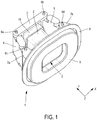
- the figure 1 shows the device 1 comprising a camera 2 mounted on a support 3 in its retracted position. Said camera 2 is also inserted into a secondary support 15 of square shape having a central cavity allowing the insertion of the camera 2 of any shape, preferably cubic.
- the secondary support 15 is inserted into the support 3 by a square-shaped recess adapted to receive the secondary support 15.
- the secondary support 15, associated with the support 3 allows the camera 2 to be tilted before mounting the device 1.
- the tilt of the camera 2 makes it possible to adapt its field of vision to the vehicle of which the device 1 is integrated. Indeed, depending on the type of vehicle, the inclination of the camera 2 will not be the same due to the difference in height of each vehicle. Thus, the inclination of the camera 2 adapted according to the vehicle allows the driver to benefit from the most optimal field of vision from outside the vehicle.
- the connecting rod 4 is connected by one of its ends to one of the ends of the support 3 by the fixing means 6a passing through a recess thus connecting the two parts 3 and 4.
- the connecting rod 5 is connected by one of its ends at the other end of the support 3 by the fixing means 6b passing through a recess thus connecting the two parts 3 and 5.
- a cover 7 is divided into two parts 7a and 7b. During the closed position of the cover, the parts 7a and 7b are complementary and fit into each other by their ends and form a single part 7.
- the connecting rod 4 is connected at the other of its ends to the part 7a of the cover 7 by the fixing means 6c passing through a recess thus connecting the two parts 4 and 7a and the connecting rod 5 is connected at the other of its ends to the part 7b of the cover 7 by the fixing means 6d passing through a recess thus connecting the two parts 5 and 7b.
- These fixing means 6 will be able to move along a determined path 10 in the form of cavities as presented in the Figures 2a and 2b .
- Said fixing means 6a and 6b are rods able to be inserted into recesses passing through said support 3 and said fixing means 6c and 6d are rods capable of being inserted into recesses passing through said cover 7.
- a joint 8 in polyurethane, or another material with a sealing function is inserted between the metal sheet (not shown) of the vehicle and a logo 9 so as to reinforce the sealing and the mechanical resistance of the device 1.
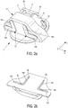
- the figure 2a shows the underside of the device 1 and the paths 10 which each end of the fixing means 6 follows when the device 1 is activated.
- the fixing means 6a and 6b take the paths 10a and 10b respectively while the fixing means 6c and 6d take paths 10c and 10d respectively.
- the paths 10a and 10b are respectively perpendicular to the paths 10c and 10d.
- the fixing means 6a and 6b are in abutment respectively in the paths 10a and 10b at their upper end during the retracted position of the camera and move during the deployment of the camera to its capture position until the stop of the 'lower end of paths 10a and 10b.
- the fastening means 6c and 6d are not in abutment respectively on the paths 10c and 10d when the camera is retracted as shown in the figure 2b to keep an angle of less than 90 ° between the cover and the connecting rods 4 and 5 in order to make the opening of the cover more fluid when the device is activated.
- the fixing means 6c and 6d are in abutment distally respectively to the paths 10c and 10d.
- the figure 2b shows a cross-sectional view of paths 10a to 10d. Said cavity paths in a receptacle 12. Said cavities receive the fixing means 6 allowing the movement of the camera 2 and the cover 7 by means of the connecting rods 4 and 5 not shown in this figure.
- one of the ends of the fixing means 6a and 6b is nested in the paths 10a and 10b respectively and one of the ends of the fixing means 6c and 6d is nested in the paths 10c and 10d respectively.
- the fixing means 6a and 6b move respectively in the cavities of the paths 10a and 10b according to a movement in translation, parallel to the movement of the camera 2 and the fixing means 6c and 6d move respectively in the cavities of the paths 10c and 10d in a translational movement, perpendicular to the movement of the camera 2 and parallel to the movement of the cover 7.
- the cavities have a certain depth allowing insertion of the ends of the fixing means as well as a width sufficient to receive the ends of the fixing means having a determined size while tolerating the displacement of the ends of the fixing means in these cavities.
- the figure 3 shows the device 1 in section in which is shown a camera 2 mounted on its support 3, the connecting rods 4 and 5 as well as the cover 7 and the fixing means 6a to 6d.
- the camera 2 moves from a retracted position to a capture position simultaneously with the cover 7 from a closed position to an open position.
- the displacement in translation of the fastening means 6a and 6b along the paths 10a and 10b causes the transposition of the camera 2 along the Y axis (cf. fig. 1 ) while simultaneously, the fastening means 6c and 6d move in translation along the paths 10c and 10d causing the longitudinal displacement of the parts 7a and 7b of the cover 7 and therefore the opening of the cover 7 along the axis X.
- the camera 2 in the capture position passes through the opening created by the cover as well as the seal 8 made of polyurethane, or of another material having a sealing function, and the metal sheet of the vehicle in order to capture the images located on the vehicle exterior.
- the fixing means 6a and 6b return to their initial position as shown in the figure 3 by taking the same paths 10a and 10b while, simultaneously, the fixing means 6c and 6d also return to their initial position as shown in this same figure by taking the same paths 10c and 10d thus causing the displacement in the closed position of the parts 7a and 7b of the cover 7 along the X axis.
- the parts 7a and 7b form a single cover 7 so that the closed position has an anti-theft 11 and protective function against elements such as dust, water or ice from the camera 2 due to the complementarity of the ends of the parts 7a and 7b.
- the device 1 is located at the rear of the vehicle and more particularly at the center of the logo 9 of said vehicle, so that the cover 7 opens at the center of said logo 9 and therefore that the camera 2 transposes from its retracted position to its capture position by a translational movement capable of passing said camera 2 through an orifice of said vehicle logo 9.
- said logo 9 is merged with the cover 7 and capable of dividing into two parts in order to allow the camera 2 to pass from the retracted position to the capture position simultaneously with the division into two parts.
- the figure 4 shows a part of the device 1 in which is shown the support 3 receiving the camera (not shown) via the secondary support (not shown), the cover 7 as well as the connecting rods 4 and 5 connecting the support 3 and the cover 7 using fixing means 6.
- the device 1 being in its retracted position, the cover 7 is in the closed position and the part of the device 1 is in the shape of a trapezoid.
- the recess making it possible to nest the secondary support 15, which itself supports the camera 2, is centered on the cover 7, by the trapezoid shape of this part of the device 1, which induces a transposition of the camera 2 in the middle of the cover 7 when it opens shares the division of parts 7a and 7b of said cover 7.
- the connecting rods 4 and 5 have a cross shape, the parts of which are connected to the support 3 and to each part 7a and 7b of the cover 7 have a recess receiving the fixing means 6 and having a length greater than the other parts of said connecting rods 4 and 5 .
- the figure 5a shows the cover 7 as well as the seal 8 made of polyurethane, or of another material having a sealing function, and the logo 9 of the device 1 can be of any shape such as a square, rectangle, circle, rhombus, triangle, and other compatible forms.
- the opening of the cover 7 by the division of the parts 7a and 7b takes place at its center as illustrated in this figure.
- the seal 8 made of polyurethane or another material having a sealing function, is fixed between the metal sheet (not shown) and the logo 9.
- This seal 8 is arranged around said logo 9.
- the opening of the logo 9 of the vehicle is centered on the middle of the cover 7 so as to allow the camera to pass when the device 1 is activated by opening the cover 7 and through the orifice of the logo 9 because, as explained in the figure 4 , the camera is centered on the cover 7.
- the figure 5b shows a back view of the figure 5a .
- the secondary support 15 of the camera is nested in the support 3 and centered on the cover 7 as well as the orifice of the logo 9.
- the part of the device 1 illustrated in the figure 4 does not extend beyond the seal 8 when the camera is retracted.
- the figure 6a shows the part of the device 1 visible from the outside of the vehicle.
- a seal 8 made of polyurethane, or any other material having a sealing function is located between the metal sheet 13 of the opening leaf such as the trunk or a tailgate for example of a vehicle and the logo 9.
- the seal 8 protects the device 1 by a tightness and an increased mechanical resistance which could be altered between the mechanical sheet 13 and the logo 9 of the vehicle in the absence of said seal 8.
- the camera When the camera is captured, the camera transposes the cover 7 when it opens as well as the orifice of the logo 9 so as to obtain an optimal field of vision of the external environment of the vehicle in a mode preferred embodiment.
- the figure 6b shows a back view of the figure 6a .
- a receptacle 12 comprising the device 1 is fixed to the mechanical sheet 13 of the vehicle.
- the receptacle 12 aims to protect the device 1 and also to form the paths 10 by the formation of cavities in this receptacle 12 intended to receive the fixing means 6.
- only the paths of the upper face of the receptacle are visible, it is understood that the same paths are present on the underside of said receptacle 12, that is to say that there is symmetry with respect to the longitudinal plane and to the transverse plane of each L-shaped path.
- the receptacle 12 extends beyond the polyurethane seal, or another material having a sealing function to receive the parts of the cover when it is in position opened.
- the receptacle therefore has the shape of the parts assembled inside this receptacle 12, thus making it possible to limit the space covered by the device inside the vehicle.
- the figure 7 shows the camera 2 mounted on its secondary support 15, itself mounted on the support 3.
- the camera 2 can be pre-tilted with a tilt angle determined according to the type of vehicle equipped with the device 1 of the present invention.
- the inclination of the camera 2 is adjusted before final mounting of the camera 2 in the device 1.
- an adjustment lug 23 is disposed on the secondary support 15 and extending through a lateral branch of the support 3 to manually adjust the tilt of the camera 2.
- the adjustment lug 23 is able to be moved along a transverse axis (Z) parallel to the direction of movement of the camera 2 from its rest position to its capture position by a recess created through the lateral branch of the support 3. You can also motorize the camera setting for more flexibility for the user.
- the figure 8 shows a side view of the device 1 with a diagram of an actuator 18 positioned above the axis of movement of the camera 2. In this figure, the camera 2 is in the retracted position.
- the actuator 18 comprises a motor 19 connected to a toothed wheel 20 (teeth not shown) by means of a cam 21.
- the toothed wheel 20 is in contact with a toothed screw 22 (teeth not shown).
- the toothed screw 22 is fixed to the rear of the support 3, that is to say on the side opposite to the insertion of the camera 2 into the support.
- the connection between the screw 22 and the support 3 must be free in rotation but integral in translation, a bayonet type connection would be a preferred embodiment.
- the toothed screw 22 is fixed to the center of the support 3. It can be seen that during the retracted position of the camera 2, the toothed wheel 20 is located close to the support 3.
- the motor 19 is arranged perpendicular to the toothed wheel 20 via the cam 21 and parallel to the movement of the camera 2.
- the toothed screw 22 is arranged perpendicular to the gear 20 and parallel to the movement of the camera 2.
- the actuator 18 is inserted into a sub-module (not shown) fixed to the receptacle 12 or forming part of the latter for example to improve the seal.
- the figure 9 shows a perspective view of the device 1 with an actuator 18 positioned above the axis of movement of the camera 2.
- the camera 2 is in the capture position and the camera is tilted at a determined angle.
- the toothed wheel 20 is situated opposite the support 3, unlike in the retracted position of the camera 2 as described in the figure 8 , still in contact with the toothed screw 22.
- the figure 10 shows a schematic top view of an alternative embodiment of the device 1 in which an actuator 18 is positioned coaxially with the movement of the camera 2.
- the camera is in the retracted position.
- the actuator 18 is arranged on the same axis as the axis of movement of the camera 2.
- the toothed screw 22 is fixed to the support 3 into which the camera 2 is inserted.
- the cover 7 is connected to the support 3 via the connecting rods 4 and 5. More specifically, the part of the cover 7a is connected to the support 3 via the connecting rod 4 and the part of the cover 7b is connected to the support 3 by means of the connecting rod 5.
- a logo 9 fixed on the sheet 13 of a motor vehicle.
- the actuator 18 is inserted into a sub-module (not shown) fixed to the receptacle 12.
- the motor 19 When the motor 19 is activated, for example when the reverse gear of a motor vehicle is activated, the motor 19 rotates the toothed wheel 20 clockwise via a cam 21. Then, the first toothed wheel 20, being in movement and in contact with a toothed screw 22, drives this toothed screw 22 in movement counterclockwise for example by moving along this toothed screw 22, which causes the thrust of the support 3 to which the toothed screw 22 is fixed and therefore the movement of the camera 2 from its retracted position to its capture position in a translatory movement.
- the toothed wheel 20 rotates counterclockwise and causes the movement of the toothed screw 22 clockwise by the movement of the toothed wheel 20 in the opposite direction to the direction of movement of the toothed wheel 20 when the reverse gear of a motor vehicle is activated.
- This therefore causes the return of the camera 2 to its initial position by a traction exerted by the toothed screw 22 on the support 3 of which said screw 22 is integral.
- the directions of rotation can be reversed.
Abstract
L'invention concerne un dispositif (1) pour véhicule motorisé comprenant une caméra (2) montée sur un support (3), ladite caméra (2) étant transposable d'une position rétractée à une position de capture à travers un cache (7) par un actionneur (18), ledit cache (7) est apte à se déplacer dans les deux sens entre une position fermée et une position ouverte, simultanément avec le déplacement de ladite caméra (2), ledit cache (7) étant apte à se diviser en deux parties (7a) et (7b) par un déplacement longitudinal suivant un axe (X), perpendiculaire à l'axe (Y), desdites parties, ladite caméra (2) étant apte à se déplacer suivant un axe transversal (Z) par rapport au déplacement desdites parties (7a) et (7b), caractérisé en ce que ledit actionneur (18) comprend un moteur (19) relié à une roue dentée (20) par l'intermédiaire d'une came (21), ladite roue dentée (20) étant en contact avec une vis dentée (22), ladite vis dentée (22) étant apte à déplacer ladite caméra (2) selon un mouvement translatoire.The invention relates to a device (1) for a motor vehicle comprising a camera (2) mounted on a support (3), said camera (2) being transposable from a retracted position to a capture position through a cover (7). by an actuator (18), said cover (7) is able to move in both directions between a closed position and an open position, simultaneously with the movement of said camera (2), said cover (7) being able to move dividing into two parts (7a) and (7b) by a longitudinal displacement along an axis (X), perpendicular to the axis (Y), of said parts, said camera (2) being able to move along a transverse axis (Z ) with respect to the movement of said parts (7a) and (7b), characterized in that said actuator (18) comprises a motor (19) connected to a toothed wheel (20) via a cam (21), said toothed wheel (20) being in contact with a toothed screw (22), said toothed screw (22) being able to move said camera (2) according to a tr anslatory.
Description
L'invention se rapporte à un dispositif de déploiement d'une caméra pour véhicule motorisé.The invention relates to a device for deploying a camera for a motor vehicle.
La caméra est disposée à l'arrière du véhicule préférentiellement mais peut tout à fait être utilisée ailleurs pour une caméra avant ou sur rétroviseur latéral, par exemple au niveau du logo arrière du véhicule. Son déploiement d'une position rétractée à une position de capture s'effectue par un activateur, par exemple la position marche arrière du véhicule.The camera is preferably placed at the rear of the vehicle but can quite well be used elsewhere for a front camera or on a side mirror, for example at the level of the rear logo of the vehicle. Its deployment from a retracted position to a capture position is effected by an activator, for example the reverse position of the vehicle.
Lors de la position de capture de la caméra, ladite caméra enregistre les images de l'environnement extérieur du véhicule et les retransmets instantanément sur un écran disposé sur le tableau de bord de manière à ce que le conducteur soit alerté par tout danger suite à une manœuvre dont le conducteur ne peut prendre connaissance avec les moyens classiques d'un véhicule, par exemple lors d'une manœuvre de marche arrière du véhicule.When the camera is captured, said camera records images of the vehicle's external environment and instantly transmits them to a screen on the dashboard so that the driver is alerted to any danger following a maneuver of which the driver cannot take cognizance with conventional means of a vehicle, for example during a reverse maneuver of the vehicle.
Un dispositif de déploiement d'une caméra pour véhicule motorisé est connu de l'art antérieur. Un dispositif à double fonction d'ouverture d'un verrou lors de l'actionnement d'une poignée et, si nécessaire, d'utilisation d'une caméra pour capturer l'extérieur du véhicule est connu dans
Un autre dispositif pour véhicule automobile est connu dans
Ces dispositifs connus de l'art antérieur présentent des inconvénients. Les dispositifs connus de l'art antérieur prennent un espace plus important compte tenu de la position de l'actionneur. Les actionneurs exercent également plus de contrainte pour déplacer une telle caméra du fait du type de mouvement exercé par l'actionneur, par exemple un mouvement rotatoire.These devices known from the prior art have drawbacks. The known devices of the prior art take up more space taking into account the position of the actuator. The actuators also exert more constraint to move such a camera due to the type of movement exerted by the actuator, for example a rotary movement.
Cette invention vise à remédier à ces inconvénients en fournissant un dispositif pour véhicule motorisé comprenant une caméra montée sur un support, ladite caméra étant transposable d'une position rétractée à une position de capture à travers un cache par un actionneur, ledit cache est apte à se déplacer dans les deux sens entre une position fermée et une position ouverte, simultanément avec le déplacement de ladite caméra, ledit cache étant apte à se diviser en deux parties par un déplacement longitudinal suivant un premier axe X, perpendiculaire à un deuxième axe Y, desdites parties, ladite caméra (2) étant apte à se déplacer suivant le deuxième axe transversal Y par rapport au déplacement desdites parties (7a) et (7b), caractérisé en ce que ledit actionneur comprend un moteur relié à une roue dentée par l'intermédiaire d'une came, ladite roue dentée étant en contact avec une vis dentée, ladite vis dentée étant apte à déplacer ladite caméra selon un mouvement translatoire.This invention aims to remedy these drawbacks by providing a device for a motor vehicle comprising a camera mounted on a support, said camera being transposable from a retracted position to a capture position through a cover by an actuator, said cover is suitable for move in both directions between a closed position and an open position, simultaneously with the movement of said camera, said cover being able to be divided into two parts by a longitudinal movement along a first axis X, perpendicular to a second axis Y, of said parts, said camera (2) being able to move along the second transverse axis Y with respect to the movement of said parts (7a) and (7b), characterized in that said actuator comprises a motor connected to a toothed wheel by the through a cam, said toothed wheel being in contact with a toothed screw, said toothed screw being able to move said camera in a translatory movement.
Préférentiellement, la transposition d'une position rétractée à une position de capture de la caméra s'effectue par le moyen de bielles et encore préférentiellement, le déplacement du cache de la position fermée à la position ouverte se fait par le moyen des mêmes bielles. Ceci permet de transmettre le mouvement de la camera au cache.Preferably, the transposition of a retracted position to a position for capturing the camera is carried out by means of connecting rods and more preferably, the displacement of the cover from the closed position to the open position is carried out by means of the same connecting rods. This allows the movement of the camera to be transmitted to the cache.
Dans un mode de réalisation préféré, les bielles sont reliées entre elles par l'intermédiaire d'un support par des moyens de fixation, et idéalement, les moyens de fixation sont des tiges aptes à s'insérer dans des évidements traversant le support. Dans un autre mode de réalisation préféré, les bielles sont reliées au cache par des moyens de fixation et idéalement, les moyens de fixation sont des tiges aptes à s'insérer dans des évidements traversant le cache. Ceci permet de transmettre efficacement le mouvement de la camera au cache.In a preferred embodiment, the connecting rods are connected together by means of a support by fixing means, and ideally, the fixing means are rods capable of being inserted into recesses passing through the support. In another preferred embodiment, the connecting rods are connected to the cover by fixing means and ideally, the fixing means are rods capable of being inserted in recesses passing through the cover. This allows the movement of the camera to be efficiently transmitted to the cache.
De manière préférentielle, les moyens de fixation sont aptes à se déplacer selon un chemin déterminé et idéalement, le chemin a une forme de L. Cette conformation permet de transformer le déplacement longitudinal de la camera en un mouvement dans une direction transversale des parties du cache.Preferably, the fixing means are able to move along a determined path and ideally, the path has an L shape. This conformation makes it possible to transform the longitudinal displacement of the camera into a movement in a transverse direction of the parts of the cover. .
Dans un autre mode de réalisation préféré, le cache se divise en deux parties en son milieu lorsqu'il passe d'une position fermée à une position ouverte. Cela permet d'optimiser le déport des parties de cache.In another preferred embodiment, the cover is divided into two parts in the middle when it passes from a closed position to an open position. This optimizes the offset of the cache parts.
Idéalement, l'extrémité de contact de l'une des parties du cache a une forme en V et l'autre extrémité de contact de l'autre partie du cache a une forme complémentaire à la forme en V de sorte que les deux extrémités des parties s'emboitent lors de la position fermée dudit cache. En outre, on favorise l'accostage des deux parties.Ideally, the contact end of one of the parts of the cover has a V shape and the other contact end of the other part of the cover has a shape complementary to the V shape so that the two ends of the parts fit together in the closed position of said cover. In addition, it favors the docking of the two parts.
De manière préférentielle, le déplacement du dispositif est effectué par un activateur tel que la position marche arrière d'un véhicule ou un bouton d'activation. L'avantage étant une commande depuis l'habitacle du véhicule.Preferably, the movement of the device is carried out by an activator such as the reverse position of a vehicle or an activation button. The advantage being control from the passenger compartment of the vehicle.
D'une autre manière préférentielle, la caméra se transpose de la position rétractée à la position de capture par un mouvement de translation apte à faire passer la caméra à travers un orifice de logo de véhicule et encore d'une autre manière préférentielle, le cache est confondu avec un logo de véhicule et apte à se diviser en deux parties afin de permettre à la caméra de passer de la position rétractée à la position de capture simultanément à la division des deux parties.In another preferential manner, the camera transposes from the retracted position to the capture position by a translational movement capable of passing the camera through a vehicle logo orifice and still in another preferential manner, the cover is confused with a vehicle logo and able to divide into two parts in order to allow the camera to pass from the retracted position to the capture position simultaneously with the division of the two parts.
Idéalement, un joint est interposé entre le dispositif et un logo de véhicule, le joint reposant sur une surface plane d'une tôle métallique appartenant à un ouvrant arrière du véhicule. Cela améliore l'étanchéité.Ideally, a seal is interposed between the device and a vehicle logo, the seal resting on a flat surface of a metal sheet belonging to a rear window of the vehicle. This improves sealing.
Encore idéalement, la caméra est apte à être inclinée selon un troisième axe perpendiculaire par rapport au déplacement de la caméra par l'intermédiaire d'un dispositif de réglage. Cela permet de s'adapter aux différentes hauteurs de véhicules, sans impacter la visibilité.Still ideally, the camera is able to be tilted along a third axis perpendicular to the movement of the camera by means of an adjustment device. This makes it possible to adapt to the different heights of vehicles, without impacting visibility.
Selon un mode de réalisation, le troisième axe est confondu avec ou est parallèle au premier axe.According to one embodiment, the third axis is coincident with or is parallel to the first axis.
Dans une autre variante, la camera est disposée entre le moteur et le cache. Cela permet d'optimiser l'encombrement radial.In another variant, the camera is placed between the motor and the cover. This optimizes the radial size.
Encore dans une autre variante, le moteur est disposé autour de la camera et sur un plan perpendiculaire à l'axe de déplacement de la camera, cette dernière et le moteur étant coplanaires. Cela permet d'optimiser l'encombrement longitudinal.In yet another variant, the motor is arranged around the camera and on a plane perpendicular to the axis of movement of the camera, the latter and the motor being coplanar. This optimizes the longitudinal dimensions.
Chaque disposition de l'actionneur a son avantage selon le type de véhicule équipé d'un tel dispositif. Le dispositif peut tout à fait être utilisé pour une application de type rétroviseur avec camera.Each arrangement of the actuator has its advantage depending on the type of vehicle equipped with such a device. The device can completely be used for a mirror-type application with camera.
Le déplacement longitudinal des deux parties du cache lors de son ouverture permet à la caméra de se déplacer simultanément vers sa position de capture sans réduire son champ de vision, les parties du cache n'étant plus visible de l'extérieur du véhicule lors de leurs positions ouvertes.The longitudinal displacement of the two parts of the cover when it is opened allows the camera to move simultaneously to its capture position without reducing its field of vision, the parts of the cover being no longer visible from outside the vehicle when they are open positions.
Lors de la position fermée du cache, celui-ci a une fonction d'antivol et de protection de la caméra contre l'environnement extérieur (poussière, boue, eau...). Cette conformation a pour but d'optimiser la protection de la caméra lors de sa position rétractée.When the cover is closed, it has an anti-theft and protection function for the camera against the external environment (dust, mud, water, etc.). The purpose of this conformation is to optimize the protection of the camera during its retracted position.
L'invention sera décrite plus en détails à travers les différentes figures présentées ci-dessous, ce qui facilitera sa compréhension.
- La
figure 1 représente une vue en perspective de dessus du dispositif conformément à l'invention sans l'actionneur. - La
figure 2a représente une vue en perspective du dessous du dispositif conformément à l'invention sans l'actionneur. - La
figure 2b représente une vue en coupe des chemins de lafigure 2b conformément à l'invention sans l'actionneur. - La
figure 3 représente une vue en coupe de lafigure 1 conformément à l'invention sans l'actionneur. - La
figure 4 représente une vue en perspective d'une partie du dispositif de lafigure 1 conformément à l'invention. - La
figure 5a est une vue de face avant d'une partie du dispositif conformément à l'invention. - La
figure 5b est une vue de face arrière de lafigure 5a conformément à l'invention. - La
figure 6a est une vue en perspective de la partie visible du dispositif de l'extérieur du véhicule conformément à l'invention. - La
figure 6b est une vue en perspective de derrière de lafigure 6a conformément à l'invention sans l'actionneur. - La
figure 7 est une vue de la caméra sur son support, conformément à l'invention. - La
figure 8 est une vue de côté du dispositif avec l'actionneur positionné au-dessus, conformément à l'invention. - La
figure 9 est une vue en perspective du dispositif avec l'actionneur positionné au-dessus et la caméra en position de capture. - La
figure 10 est une vue de dessus du dispositif avec l'actionneur positionné co-axialement au déplacement de la caméra.
- The
figure 1 shows a perspective view from above of the device according to the invention without the actuator. - The
figure 2a shows a perspective view from below of the device according to the invention without the actuator. - The
figure 2b represents a sectional view of the paths of thefigure 2b according to the invention without the actuator. - The
figure 3 represents a sectional view of thefigure 1 according to the invention without the actuator. - The
figure 4 represents a perspective view of part of the device of thefigure 1 according to the invention. - The
figure 5a is a front view of a part of the device according to the invention. - The
figure 5b is a rear front view of thefigure 5a according to the invention. - The
figure 6a is a perspective view of the visible part of the device from the outside of the vehicle according to the invention. - The
figure 6b is a perspective view from behind of thefigure 6a according to the invention without the actuator. - The
figure 7 is a view of the camera on its support, in accordance with the invention. - The
figure 8 is a side view of the device with the actuator positioned above, in accordance with the invention. - The
figure 9 is a perspective view of the device with the actuator positioned above and the camera in the capture position. - The
figure 10 is a top view of the device with the actuator positioned co-axially with the movement of the camera.
Il est entendu que la description des modes de réalisation suivants est en aucun cas limitative de la portée de l'invention, c'est-à-dire que les combinaisons ou les modifications simples des modes de réalisation présentées ci-après sont également couverts par la portée de l'invention.It is understood that the description of the following embodiments is in no way limiting the scope of the invention, that is to say that the combinations or simple modifications of the embodiments presented below are also covered by the scope of the invention.
La
Le support secondaire 15 est inséré dans le support 3 par un évidement de forme carré adapté pour recevoir le support secondaire 15. Le support secondaire 15, associé au support 3 permet une inclinaison de la caméra 2 avant le montage du dispositif 1. L'inclinaison de la caméra 2 permet d'adapter son champ de vision au véhicule dont le dispositif 1 est intégré. En effet, selon le type de véhicule, l'inclinaison de la caméra 2 ne sera pas la même du fait de la différence de hauteur de chaque véhicule. Ainsi, l'inclinaison de la caméra 2 adaptée selon le véhicule permet au conducteur de bénéficier du champ de vision le plus optimal de l'extérieur du véhicule.The
Deux bielles 4 et 5 sont reliées au support 3 par des moyens de fixation 6a et 6b. La bielle 4 est reliée par l'une de ses extrémités à l'une des extrémités du support 3 par le moyen de fixation 6a traversant un évidement reliant ainsi les deux pièces 3 et 4. La bielle 5 est reliée par l'une de ses extrémités à l'autre extrémité du support 3 par le moyen de fixation 6b traversant un évidement reliant ainsi les deux pièces 3 et 5.Two connecting
Un cache 7 est divisé en deux parties 7a et 7b. Lors de la position fermée du cache, les parties 7a et 7b sont complémentaires et s'emboitent l'une dans l'autre par leurs extrémités et forment une seule partie 7. La bielle 4 est reliée à l'autre de ses extrémités à la partie 7a du cache 7 par le moyen de fixation 6c traversant un évidement reliant ainsi les deux pièces 4 et 7a et la bielle 5 est reliée à l'autre de ses extrémités à la partie 7b du cache 7 par le moyen de fixation 6d traversant un évidement reliant ainsi les deux pièces 5 et 7b. Ces moyens de fixation 6 seront aptes à se déplacer selon un chemin déterminé 10 sous forme de cavités comme présenté dans les
Lesdits moyens de fixation 6a et 6b sont des tiges aptes à s'insérer dans des évidements traversant ledit support 3 et lesdits moyens de fixation 6c et 6d sont des tiges aptes à s'insérer dans des évidements traversant ledit cache 7. Un joint 8 en polyuréthane, ou en un autre matériau ayant une fonction d'étanchéité est inséré entre la tôle métallique (non représentée) du véhicule et un logo 9 de telle sorte à renforcer l'étanchéité et la résistance mécanique du dispositif 1.Said fixing means 6a and 6b are rods able to be inserted into recesses passing through said
La
Les chemins 10a et 10b sont respectivement perpendiculaires par rapport aux chemins 10c et 10d. Les moyens de fixation 6a et 6b sont en butée respectivement dans les chemins 10a et 10b à leur extrémité supérieure lors de la position rétractée de la caméra et se déplacent lors du déploiement de la caméra à sa position de capture jusqu'à la butée de l'extrémité inférieure des chemins 10a et 10b. Les moyens de fixations 6c et 6d ne sont pas en butée respectivement sur les chemins 10c et 10d lors de la position rétractée de la caméra comme représenté dans la
Les chemins 10a et 10c ainsi que les chemins 10b et 10d ont tous deux une forme de L formant une cavité pour recevoir les extrémités des moyens de fixation 6 appropriés et principalement pour guider lesdites extrémités de manière stable. Il est entendu que la forme desdits chemins est une forme en L dans n'importe quel sens géométrique.The
La
Les moyens de fixation 6a et 6b se déplacent respectivement dans les cavités des chemins 10a et 10b selon un mouvement en translation, parallèle au mouvement de la caméra 2 et les moyens de fixation 6c et 6d se déplacent respectivement dans les cavités des chemins 10c et 10d selon un mouvement en translation, perpendiculaire au mouvement de la caméra 2 et parallèle au mouvement du cache 7.The fixing means 6a and 6b move respectively in the cavities of the
Les cavités ont une certaine profondeur permettant une insertion des extrémités des moyens de fixation ainsi qu'une largeur suffisante pour recevoir les extrémités des moyens de fixation ayant une taille déterminée tout en tolérant le déplacement des extrémités des moyens de fixation dans ces cavités.The cavities have a certain depth allowing insertion of the ends of the fixing means as well as a width sufficient to receive the ends of the fixing means having a determined size while tolerating the displacement of the ends of the fixing means in these cavities.
Il est à noter qu'il y a une symétrie par rapport au plan longitudinal et au plan transversal de chaque chemin en forme de L.It should be noted that there is symmetry with respect to the longitudinal plane and to the transverse plane of each L-shaped path.
La
Le déplacement en translation des moyens de fixations 6a et 6b le long des chemins 10a et 10b entraine la transposition de la caméra 2 selon l'axe Y (cf.
La caméra 2 en position de capture, traverse l'ouverture créée par le cache ainsi que le joint 8 en polyuréthane, ou en un autre matériau ayant une fonction d'étanchéité, et la tôle métallique du véhicule afin de capturer les images situées à l'extérieur du véhicule.The
Lors de la rétractation de la caméra 2 dans sa position rétractée selon l'axe Y, les moyens de fixation 6a et 6b retournent dans leur position initiale telle que représentée sur la
Lors de la position inactive du dispositif 1, les parties 7a et 7b forment un unique cache 7 de telle sorte que la position fermée a une fonction d'antivol 11 et de protection contre les éléments tels que la poussière, l'eau ou la glace de la caméra 2 du fait de la complémentarité des extrémités des parties 7a et 7b.During the inactive position of the
Dans une variante de l'invention préférée, le dispositif 1 se situe à l'arrière du véhicule et plus particulièrement au centre du logo 9 dudit véhicule, de telle sorte que le cache 7 s'ouvre au niveau du centre dudit logo 9 et donc que la caméra 2 se transpose de sa position rétractée à sa position de capture par un mouvement de translation apte à faire passer ladite caméra 2 à travers un orifice dudit logo 9 de véhicule.In a variant of the preferred invention, the
Dans une autre variante de l'invention, ledit logo 9 est confondu avec le cache 7 et apte à se diviser en deux parties afin de permettre à la caméra 2 de passer de la position rétractée à la position de capture simultanément à la division en deux parties.In another variant of the invention, said
La
Le dispositif 1 étant dans sa position rétractée, le cache 7 est en position fermée et la partie du dispositif 1 est en forme de trapèze. L'évidement du support 3, en forme de carré permet d'imbriquer le support secondaire 15 à l'aide de supports de fixation 14 situés de part et d'autre sur les faces intérieures des branches verticales du support 3.The
L'évidement, permettant d'imbriquer le support secondaire 15, qui lui-même supporte la caméra 2, est centré sur le cache 7, de par la forme de trapèze de cette partie du dispositif 1, ce qui induit une transposition de la caméra 2 au milieu du cache 7 lors de son ouverture part la division des parties 7a et 7b dudit cache 7.The recess, making it possible to nest the
Les bielles 4 et 5 ont une forme de croix, dont les parties reliées au support 3 et à chaque partie 7a et 7b du cache 7 ont un évidement recevant les moyens de fixation 6 et présentant une longueur supérieure aux autres parties desdites bielles 4 et 5.The connecting
La
L'ouverture du cache 7 par la division des parties 7a et 7b s'effectue en son centre comme illustré sur cette figure. Le joint 8 en polyuréthane ou en un autre matériau ayant une fonction d'étanchéité, est fixé entre la tôle métallique (non représentée) et le logo 9. Ce joint 8 est disposé autour dudit logo 9. L'orifice du logo 9 du véhicule est centré sur le milieu du cache 7 de manière à laisser passer la caméra lors de l'activation du dispositif 1 par l'ouverture du cache 7 et à travers l'orifice du logo 9 car, comme expliqué dans la
La
La
Lors de la position de capture de la caméra, la caméra traverse par transposition le cache 7 lors de son ouverture ainsi que l'orifice du logo 9 de telle sorte à obtenir un champ de vision optimal de l'environnement extérieur du véhicule dans un mode de réalisation préféré.When the camera is captured, the camera transposes the
La
Le réceptacle 12 s'étend au-delà du joint en polyuréthane, ou en un autre matériau ayant une fonction d'étanchéité pour recevoir les parties du cache lors de sa position ouverte. Le réceptacle a donc la forme des pièces assemblées intérieures à ce réceptacle 12, permettant ainsi de limiter l'espace couvert par le dispositif à l'intérieur du véhicule.The
La
L'ergot de réglage 23 est apte à être déplacer selon un axe transversal (Z) parallèle à la direction de déplacement de la caméra 2 de sa position de repos à sa position de capture de par un évidement créé à travers la branche latérale du support 3. On peut aussi motoriser le réglage de la camera pour plus de flexibilité de l'utilisateur.The
La
L'actionneur 18 comprend un moteur 19 relié à une roue dentée 20 (dents non représentées) par l'intermédiaire d'une came 21. La roue dentée 20 est en contact avec une vis dentée 22 (dents non représentées). La vis dentée 22 est fixée à l'arrière du support 3, c'est-à-dire du côté opposé à l'insertion de la caméra 2 dans le support. La liaison entre la vis 22 et le support 3 doit être libre en rotation mais solidaire en translation, une liaison de type baïonnette serait un mode de réalisation préféré.The
Plus précisément, la vis dentée 22 est fixée au centre du support 3. On voit que lors de la position rétractée de la caméra 2, la roue dentée 20 est située proche du support 3. Le moteur 19 est disposé perpendiculairement à la roue dentée 20 par l'intermédiaire de la came 21 et parallèle au déplacement de la caméra 2. La vis dentée 22 est disposée perpendiculairement à la roue dentée 20 et parallèlement au déplacement de la caméra 2.More specifically, the
L'actionneur 18 est inséré dans un sous-module (non représenté) fixé au réceptacle 12 ou faisant partie de ce dernier par exemple pour améliorer l'étanchéité.The
La
La
Le cache 7 est relié au support 3 par l'intermédiaire des bielles 4 et 5. Plus précisément, la partie du cache 7a est reliée au support 3 par l'intermédiaire de la bielle 4 et la partie du cache 7b est reliée au support 3 par l'intermédiaire de la bielle 5. On voit également un logo 9 fixé sur la tôle 13 d'un véhicule automobile. L'actionneur 18 est inséré dans un sous-module (non représenté) fixé au réceptacle 12.The
Dans le paragraphe suivant, le fonctionnement de l'invention est détaillé.In the following paragraph, the operation of the invention is detailed.
Lorsque le moteur 19 est activé, par exemple lors de l'activation de la marche arrière d'un véhicule automobile, le moteur 19 fait tourner la roue dentée 20 dans le sens horaire par l'intermédiaire d'une came 21. Puis, la première roue dentée 20, étant en mouvement et en contact avec une vis dentée 22, entraîne en mouvement cette vis dentée 22 dans le sens anti horaire par exemple en se déplaçant le long de cette vis dentée 22, ce qui entraîne la poussée du support 3 auquel la vis dentée 22 est fixée et donc le déplacement de la caméra 2 de sa position rétractée à sa position de capture selon un mouvement translatoire.When the
Lors du retour de la caméra 2 dans sa position initiale, c'est-à-dire lors du déplacement de la caméra 2 de sa position de capture à sa position rétractée, la roue dentée 20 tourne dans le sens anti horaire et entraine le mouvement de la vis dentée 22 dans le sens horaire par le déplacement de la roue dentée 20 dans le sens inverse au sens de déplacement de la roue dentée 20 lors de l'activation de la marche arrière d'un véhicule automobile. Cela entraine donc le retour de la caméra 2 dans sa position initiale de par une traction exercée par la vis dentée 22 sur le support 3 duquel ladite vis 22 est solidaire. Bien entendu les sens de rotation peuvent être inversés.When the
Claims (17)
Applications Claiming Priority (1)
| Application Number | Priority Date | Filing Date | Title |
|---|---|---|---|
| FR1873146A FR3089910B1 (en) | 2018-12-18 | 2018-12-18 | CAMERA DEPLOYMENT DEVICE FOR MOTORIZED VEHICLE |
Publications (2)
| Publication Number | Publication Date |
|---|---|
| EP3670271A1 true EP3670271A1 (en) | 2020-06-24 |
| EP3670271B1 EP3670271B1 (en) | 2023-05-10 |
Family
ID=66218269
Family Applications (1)
| Application Number | Title | Priority Date | Filing Date |
|---|---|---|---|
| EP19212972.4A Active EP3670271B1 (en) | 2018-12-18 | 2019-12-02 | Deployment device of a camera for a motor-propelled vehicle |
Country Status (2)
| Country | Link |
|---|---|
| EP (1) | EP3670271B1 (en) |
| FR (1) | FR3089910B1 (en) |
Citations (6)
| Publication number | Priority date | Publication date | Assignee | Title |
|---|---|---|---|---|
| EP2054572A1 (en) | 2006-08-22 | 2009-05-06 | Huf Hülsbeck & Fürst GmbH & Co. KG | Device for opening a vehicle lock and for capturing an image on the exterior of the vehicle |
| DE102008012033A1 (en) * | 2008-02-29 | 2009-09-03 | GM Global Technology Operations, Inc., Detroit | Motor vehicle, has camera integrated in aerodynamic protective housing for monitoring environment, and completely covered with pivotable upper flap and pivotable lower flap in retracted position of camera |
| DE102010060573A1 (en) * | 2010-11-16 | 2012-05-16 | Huf Hülsbeck & Fürst Gmbh & Co. Kg | Device with a camera unit and a protective element, which has a compact trajectory |
| EP2524494A1 (en) | 2010-01-15 | 2012-11-21 | Huf Hülsbeck & Fürst GmbH & Co. KG | Simplified device of a camera unit of a motor vehicle |
| DE102016113410A1 (en) * | 2016-07-20 | 2018-01-25 | Huf Hülsbeck & Fürst Gmbh & Co. Kg | Device with a camera unit and a cover |
| DE102016119433A1 (en) * | 2016-10-12 | 2018-04-12 | Huf Hülsbeck & Fürst Gmbh & Co. Kg | camera module |
Family Cites Families (1)
| Publication number | Priority date | Publication date | Assignee | Title |
|---|---|---|---|---|
| CN106506913B (en) * | 2016-10-26 | 2019-07-26 | 捷开通讯(深圳)有限公司 | A kind of Telescopic pick-up head mechanism and electronic equipment |
-
2018
- 2018-12-18 FR FR1873146A patent/FR3089910B1/en active Active
-
2019
- 2019-12-02 EP EP19212972.4A patent/EP3670271B1/en active Active
Patent Citations (6)
| Publication number | Priority date | Publication date | Assignee | Title |
|---|---|---|---|---|
| EP2054572A1 (en) | 2006-08-22 | 2009-05-06 | Huf Hülsbeck & Fürst GmbH & Co. KG | Device for opening a vehicle lock and for capturing an image on the exterior of the vehicle |
| DE102008012033A1 (en) * | 2008-02-29 | 2009-09-03 | GM Global Technology Operations, Inc., Detroit | Motor vehicle, has camera integrated in aerodynamic protective housing for monitoring environment, and completely covered with pivotable upper flap and pivotable lower flap in retracted position of camera |
| EP2524494A1 (en) | 2010-01-15 | 2012-11-21 | Huf Hülsbeck & Fürst GmbH & Co. KG | Simplified device of a camera unit of a motor vehicle |
| DE102010060573A1 (en) * | 2010-11-16 | 2012-05-16 | Huf Hülsbeck & Fürst Gmbh & Co. Kg | Device with a camera unit and a protective element, which has a compact trajectory |
| DE102016113410A1 (en) * | 2016-07-20 | 2018-01-25 | Huf Hülsbeck & Fürst Gmbh & Co. Kg | Device with a camera unit and a cover |
| DE102016119433A1 (en) * | 2016-10-12 | 2018-04-12 | Huf Hülsbeck & Fürst Gmbh & Co. Kg | camera module |
Also Published As
| Publication number | Publication date |
|---|---|
| EP3670271B1 (en) | 2023-05-10 |
| FR3089910B1 (en) | 2022-01-21 |
| FR3089910A1 (en) | 2020-06-19 |
Similar Documents
| Publication | Publication Date | Title |
|---|---|---|
| EP1648737B1 (en) | Rear viewing device for an automobile | |
| WO2008107531A1 (en) | Automobile seat including a foldable back comprising a member defining a tablet, and automobile with such seat | |
| FR2759045A1 (en) | Display of official documents by fitting into rear view mirror of motor vehicle | |
| FR2892993A1 (en) | Aerodynamic device for e.g. minivan, has deflector displaced by tilting between retracted position in which deflector is applied on external surface of plate and active position in which deflector is projected with respect to plate | |
| FR2690177A1 (en) | Mechanism locking an instrument on a tractor. | |
| EP3670271B1 (en) | Deployment device of a camera for a motor-propelled vehicle | |
| FR3107679A1 (en) | Connection system for mounting a storage bin on a support attached to a body of a motor vehicle. | |
| EP1048521A1 (en) | Optical block mounting device on vehicle body parts | |
| EP2682546B1 (en) | Storage assembly for vehicle and dashboard comprising such an assembly | |
| WO2003062002A1 (en) | Rear shelf for motor vehicle equipped with a folding roof | |
| EP1501694A1 (en) | Retractable package shelf system for convertible vehicle with folding roof | |
| FR2888274A1 (en) | Opening frame e.g. cover of rear boot, supporting mechanism for motor vehicle, has articulated connecting rods to moved between open and closing positions, where one rod directly connects structure element and cover | |
| FR2891505A1 (en) | Headrest for motor vehicle, has connecting rod provided to connect fixed and mobile parts, and slots comprising inclined portion in which pivots housed when mobile part is in normal position, and allowing pivots to offset | |
| FR2988656A1 (en) | JOINT ASSEMBLY FOR VEHICLE SEAT | |
| FR2923756A1 (en) | Lockable and unlockable pivoting assembly e.g. front pivoting assembly, for bonnet in convertible vehicle, has hook mounted on base, and wall carried by male element of casing such that locking device releasably locks casing and base | |
| FR2910398A3 (en) | Motor vehicle seat, has base connected to floor along platform with driving unit driving backrest with respect to base, where driving unit includes rod with toothed wheel that is fixed to another toothed wheel of rotational axis | |
| FR3085641A1 (en) | SYSTEM FOR FIXING A PORTABLE ELECTRONIC DEVICE HOLDER IN A VEHICLE INTERIOR | |
| FR2598127A1 (en) | Device for adjusting the orientation of the reflector of a motor vehicle headlight | |
| FR3064660A1 (en) | LOCKING DEVICE FOR STORAGE COMPARTMENT COVER, ASSOCIATED STORAGE COMPARTMENT AND VEHICLE THEREFOR | |
| EP1048968B1 (en) | Device for viewing images or characters | |
| EP0472454A1 (en) | Outside rearview vehicle mirror | |
| FR2831496A1 (en) | Automobile seat comprises back with shelf articulated on spindle on rear face | |
| EP4360926A1 (en) | Access device with elytre door | |
| FR3122895A1 (en) | Device for controlling a locking element for a moving part of a vehicle | |
| FR2606714A1 (en) | Vehicle rear seat with inclinable backrest |
Legal Events
| Date | Code | Title | Description |
|---|---|---|---|
| PUAI | Public reference made under article 153(3) epc to a published international application that has entered the european phase |
Free format text: ORIGINAL CODE: 0009012 |
|
| STAA | Information on the status of an ep patent application or granted ep patent |
Free format text: STATUS: THE APPLICATION HAS BEEN PUBLISHED |
|
| AK | Designated contracting states |
Kind code of ref document: A1 Designated state(s): AL AT BE BG CH CY CZ DE DK EE ES FI FR GB GR HR HU IE IS IT LI LT LU LV MC MK MT NL NO PL PT RO RS SE SI SK SM TR |
|
| AX | Request for extension of the european patent |
Extension state: BA ME |
|
| STAA | Information on the status of an ep patent application or granted ep patent |
Free format text: STATUS: REQUEST FOR EXAMINATION WAS MADE |
|
| STAA | Information on the status of an ep patent application or granted ep patent |
Free format text: STATUS: EXAMINATION IS IN PROGRESS |
|
| STAA | Information on the status of an ep patent application or granted ep patent |
Free format text: STATUS: EXAMINATION IS IN PROGRESS |
|
| 17P | Request for examination filed |
Effective date: 20201116 |
|
| RBV | Designated contracting states (corrected) |
Designated state(s): AL AT BE BG CH CY CZ DE DK EE ES FI FR GB GR HR HU IE IS IT LI LT LU LV MC MK MT NL NO PL PT RO RS SE SI SK SM TR |
|
| 17Q | First examination report despatched |
Effective date: 20201127 |
|
| RAP3 | Party data changed (applicant data changed or rights of an application transferred) |
Owner name: U-SHIN FRANCE |
|
| GRAP | Despatch of communication of intention to grant a patent |
Free format text: ORIGINAL CODE: EPIDOSNIGR1 |
|
| STAA | Information on the status of an ep patent application or granted ep patent |
Free format text: STATUS: GRANT OF PATENT IS INTENDED |
|
| INTG | Intention to grant announced |
Effective date: 20221202 |
|
| GRAS | Grant fee paid |
Free format text: ORIGINAL CODE: EPIDOSNIGR3 |
|
| GRAA | (expected) grant |
Free format text: ORIGINAL CODE: 0009210 |
|
| STAA | Information on the status of an ep patent application or granted ep patent |
Free format text: STATUS: THE PATENT HAS BEEN GRANTED |
|
| AK | Designated contracting states |
Kind code of ref document: B1 Designated state(s): AL AT BE BG CH CY CZ DE DK EE ES FI FR GB GR HR HU IE IS IT LI LT LU LV MC MK MT NL NO PL PT RO RS SE SI SK SM TR |
|
| REG | Reference to a national code |
Ref country code: GB Ref legal event code: FG4D Free format text: NOT ENGLISH |
|
| REG | Reference to a national code |
Ref country code: AT Ref legal event code: REF Ref document number: 1566398 Country of ref document: AT Kind code of ref document: T Effective date: 20230515 Ref country code: CH Ref legal event code: EP |
|
| REG | Reference to a national code |
Ref country code: DE Ref legal event code: R096 Ref document number: 602019028682 Country of ref document: DE |
|
| REG | Reference to a national code |
Ref country code: IE Ref legal event code: FG4D Free format text: LANGUAGE OF EP DOCUMENT: FRENCH |
|
| REG | Reference to a national code |
Ref country code: DE Ref legal event code: R081 Ref document number: 602019028682 Country of ref document: DE Owner name: MINEBEA ACCESSSOLUTIONS FRANCE, FR Free format text: FORMER OWNER: U-SHIN FRANCE, ALFORTVILLE, FR |
|
| RAP4 | Party data changed (patent owner data changed or rights of a patent transferred) |
Owner name: MINEBEA ACCESSSOLUTIONS FRANCE |
|
| REG | Reference to a national code |
Ref country code: LT Ref legal event code: MG9D |
|
| REG | Reference to a national code |
Ref country code: NL Ref legal event code: MP Effective date: 20230510 |
|
| REG | Reference to a national code |
Ref country code: AT Ref legal event code: MK05 Ref document number: 1566398 Country of ref document: AT Kind code of ref document: T Effective date: 20230510 |
|
| PG25 | Lapsed in a contracting state [announced via postgrant information from national office to epo] |
Ref country code: SE Free format text: LAPSE BECAUSE OF FAILURE TO SUBMIT A TRANSLATION OF THE DESCRIPTION OR TO PAY THE FEE WITHIN THE PRESCRIBED TIME-LIMIT Effective date: 20230510 Ref country code: PT Free format text: LAPSE BECAUSE OF FAILURE TO SUBMIT A TRANSLATION OF THE DESCRIPTION OR TO PAY THE FEE WITHIN THE PRESCRIBED TIME-LIMIT Effective date: 20230911 Ref country code: NO Free format text: LAPSE BECAUSE OF FAILURE TO SUBMIT A TRANSLATION OF THE DESCRIPTION OR TO PAY THE FEE WITHIN THE PRESCRIBED TIME-LIMIT Effective date: 20230810 Ref country code: NL Free format text: LAPSE BECAUSE OF FAILURE TO SUBMIT A TRANSLATION OF THE DESCRIPTION OR TO PAY THE FEE WITHIN THE PRESCRIBED TIME-LIMIT Effective date: 20230510 Ref country code: ES Free format text: LAPSE BECAUSE OF FAILURE TO SUBMIT A TRANSLATION OF THE DESCRIPTION OR TO PAY THE FEE WITHIN THE PRESCRIBED TIME-LIMIT Effective date: 20230510 Ref country code: AT Free format text: LAPSE BECAUSE OF FAILURE TO SUBMIT A TRANSLATION OF THE DESCRIPTION OR TO PAY THE FEE WITHIN THE PRESCRIBED TIME-LIMIT Effective date: 20230510 |
|
| PG25 | Lapsed in a contracting state [announced via postgrant information from national office to epo] |
Ref country code: RS Free format text: LAPSE BECAUSE OF FAILURE TO SUBMIT A TRANSLATION OF THE DESCRIPTION OR TO PAY THE FEE WITHIN THE PRESCRIBED TIME-LIMIT Effective date: 20230510 Ref country code: PL Free format text: LAPSE BECAUSE OF FAILURE TO SUBMIT A TRANSLATION OF THE DESCRIPTION OR TO PAY THE FEE WITHIN THE PRESCRIBED TIME-LIMIT Effective date: 20230510 Ref country code: LV Free format text: LAPSE BECAUSE OF FAILURE TO SUBMIT A TRANSLATION OF THE DESCRIPTION OR TO PAY THE FEE WITHIN THE PRESCRIBED TIME-LIMIT Effective date: 20230510 Ref country code: LT Free format text: LAPSE BECAUSE OF FAILURE TO SUBMIT A TRANSLATION OF THE DESCRIPTION OR TO PAY THE FEE WITHIN THE PRESCRIBED TIME-LIMIT Effective date: 20230510 Ref country code: IS Free format text: LAPSE BECAUSE OF FAILURE TO SUBMIT A TRANSLATION OF THE DESCRIPTION OR TO PAY THE FEE WITHIN THE PRESCRIBED TIME-LIMIT Effective date: 20230910 Ref country code: HR Free format text: LAPSE BECAUSE OF FAILURE TO SUBMIT A TRANSLATION OF THE DESCRIPTION OR TO PAY THE FEE WITHIN THE PRESCRIBED TIME-LIMIT Effective date: 20230510 Ref country code: GR Free format text: LAPSE BECAUSE OF FAILURE TO SUBMIT A TRANSLATION OF THE DESCRIPTION OR TO PAY THE FEE WITHIN THE PRESCRIBED TIME-LIMIT Effective date: 20230811 |
|
| PG25 | Lapsed in a contracting state [announced via postgrant information from national office to epo] |
Ref country code: FI Free format text: LAPSE BECAUSE OF FAILURE TO SUBMIT A TRANSLATION OF THE DESCRIPTION OR TO PAY THE FEE WITHIN THE PRESCRIBED TIME-LIMIT Effective date: 20230510 |
|
| PG25 | Lapsed in a contracting state [announced via postgrant information from national office to epo] |
Ref country code: SK Free format text: LAPSE BECAUSE OF FAILURE TO SUBMIT A TRANSLATION OF THE DESCRIPTION OR TO PAY THE FEE WITHIN THE PRESCRIBED TIME-LIMIT Effective date: 20230510 |
|
| PG25 | Lapsed in a contracting state [announced via postgrant information from national office to epo] |
Ref country code: SM Free format text: LAPSE BECAUSE OF FAILURE TO SUBMIT A TRANSLATION OF THE DESCRIPTION OR TO PAY THE FEE WITHIN THE PRESCRIBED TIME-LIMIT Effective date: 20230510 Ref country code: SK Free format text: LAPSE BECAUSE OF FAILURE TO SUBMIT A TRANSLATION OF THE DESCRIPTION OR TO PAY THE FEE WITHIN THE PRESCRIBED TIME-LIMIT Effective date: 20230510 Ref country code: RO Free format text: LAPSE BECAUSE OF FAILURE TO SUBMIT A TRANSLATION OF THE DESCRIPTION OR TO PAY THE FEE WITHIN THE PRESCRIBED TIME-LIMIT Effective date: 20230510 Ref country code: EE Free format text: LAPSE BECAUSE OF FAILURE TO SUBMIT A TRANSLATION OF THE DESCRIPTION OR TO PAY THE FEE WITHIN THE PRESCRIBED TIME-LIMIT Effective date: 20230510 Ref country code: DK Free format text: LAPSE BECAUSE OF FAILURE TO SUBMIT A TRANSLATION OF THE DESCRIPTION OR TO PAY THE FEE WITHIN THE PRESCRIBED TIME-LIMIT Effective date: 20230510 Ref country code: CZ Free format text: LAPSE BECAUSE OF FAILURE TO SUBMIT A TRANSLATION OF THE DESCRIPTION OR TO PAY THE FEE WITHIN THE PRESCRIBED TIME-LIMIT Effective date: 20230510 |
|
| PGFP | Annual fee paid to national office [announced via postgrant information from national office to epo] |
Ref country code: IT Payment date: 20231211 Year of fee payment: 5 Ref country code: FR Payment date: 20231220 Year of fee payment: 5 Ref country code: DE Payment date: 20231208 Year of fee payment: 5 |
|
| REG | Reference to a national code |
Ref country code: DE Ref legal event code: R097 Ref document number: 602019028682 Country of ref document: DE |
|
| PLBE | No opposition filed within time limit |
Free format text: ORIGINAL CODE: 0009261 |
|
| STAA | Information on the status of an ep patent application or granted ep patent |
Free format text: STATUS: NO OPPOSITION FILED WITHIN TIME LIMIT |
|
| 26N | No opposition filed |
Effective date: 20240213 |