EP3670001A1 - Method for cavity preservation, mixing nozzle unit and cavity preservation device with such a mixing nozzle unit - Google Patents
Method for cavity preservation, mixing nozzle unit and cavity preservation device with such a mixing nozzle unit Download PDFInfo
- Publication number
- EP3670001A1 EP3670001A1 EP18213643.2A EP18213643A EP3670001A1 EP 3670001 A1 EP3670001 A1 EP 3670001A1 EP 18213643 A EP18213643 A EP 18213643A EP 3670001 A1 EP3670001 A1 EP 3670001A1
- Authority
- EP
- European Patent Office
- Prior art keywords
- mixing nozzle
- cavity
- nozzle unit
- preservative
- rotation
- Prior art date
- Legal status (The legal status is an assumption and is not a legal conclusion. Google has not performed a legal analysis and makes no representation as to the accuracy of the status listed.)
- Granted
Links
Images


Classifications
-
- B—PERFORMING OPERATIONS; TRANSPORTING
- B05—SPRAYING OR ATOMISING IN GENERAL; APPLYING FLUENT MATERIALS TO SURFACES, IN GENERAL
- B05B—SPRAYING APPARATUS; ATOMISING APPARATUS; NOZZLES
- B05B13/00—Machines or plants for applying liquids or other fluent materials to surfaces of objects or other work by spraying, not covered by groups B05B1/00 - B05B11/00
- B05B13/06—Machines or plants for applying liquids or other fluent materials to surfaces of objects or other work by spraying, not covered by groups B05B1/00 - B05B11/00 specially designed for treating the inside of hollow bodies
- B05B13/0627—Arrangements of nozzles or spray heads specially adapted for treating the inside of hollow bodies
- B05B13/0636—Arrangements of nozzles or spray heads specially adapted for treating the inside of hollow bodies by means of rotatable spray heads or nozzles
-
- B—PERFORMING OPERATIONS; TRANSPORTING
- B05—SPRAYING OR ATOMISING IN GENERAL; APPLYING FLUENT MATERIALS TO SURFACES, IN GENERAL
- B05B—SPRAYING APPARATUS; ATOMISING APPARATUS; NOZZLES
- B05B12/00—Arrangements for controlling delivery; Arrangements for controlling the spray area
- B05B12/08—Arrangements for controlling delivery; Arrangements for controlling the spray area responsive to condition of liquid or other fluent material to be discharged, of ambient medium or of target ; responsive to condition of spray devices or of supply means, e.g. pipes, pumps or their drive means
- B05B12/12—Arrangements for controlling delivery; Arrangements for controlling the spray area responsive to condition of liquid or other fluent material to be discharged, of ambient medium or of target ; responsive to condition of spray devices or of supply means, e.g. pipes, pumps or their drive means responsive to conditions of ambient medium or target, e.g. humidity, temperature position or movement of the target relative to the spray apparatus
-
- B—PERFORMING OPERATIONS; TRANSPORTING
- B05—SPRAYING OR ATOMISING IN GENERAL; APPLYING FLUENT MATERIALS TO SURFACES, IN GENERAL
- B05B—SPRAYING APPARATUS; ATOMISING APPARATUS; NOZZLES
- B05B15/00—Details of spraying plant or spraying apparatus not otherwise provided for; Accessories
- B05B15/60—Arrangements for mounting, supporting or holding spraying apparatus
- B05B15/65—Mounting arrangements for fluid connection of the spraying apparatus or its outlets to flow conduits
- B05B15/652—Mounting arrangements for fluid connection of the spraying apparatus or its outlets to flow conduits whereby the jet can be oriented
-
- B—PERFORMING OPERATIONS; TRANSPORTING
- B05—SPRAYING OR ATOMISING IN GENERAL; APPLYING FLUENT MATERIALS TO SURFACES, IN GENERAL
- B05B—SPRAYING APPARATUS; ATOMISING APPARATUS; NOZZLES
- B05B15/00—Details of spraying plant or spraying apparatus not otherwise provided for; Accessories
- B05B15/60—Arrangements for mounting, supporting or holding spraying apparatus
- B05B15/68—Arrangements for adjusting the position of spray heads
-
- B—PERFORMING OPERATIONS; TRANSPORTING
- B05—SPRAYING OR ATOMISING IN GENERAL; APPLYING FLUENT MATERIALS TO SURFACES, IN GENERAL
- B05B—SPRAYING APPARATUS; ATOMISING APPARATUS; NOZZLES
- B05B3/00—Spraying or sprinkling apparatus with moving outlet elements or moving deflecting elements
- B05B3/02—Spraying or sprinkling apparatus with moving outlet elements or moving deflecting elements with rotating elements
- B05B3/025—Rotational joints
- B05B3/027—Rotational joints with radial fluid passages
-
- B—PERFORMING OPERATIONS; TRANSPORTING
- B05—SPRAYING OR ATOMISING IN GENERAL; APPLYING FLUENT MATERIALS TO SURFACES, IN GENERAL
- B05B—SPRAYING APPARATUS; ATOMISING APPARATUS; NOZZLES
- B05B7/00—Spraying apparatus for discharge of liquids or other fluent materials from two or more sources, e.g. of liquid and air, of powder and gas
- B05B7/02—Spray pistols; Apparatus for discharge
- B05B7/06—Spray pistols; Apparatus for discharge with at least one outlet orifice surrounding another approximately in the same plane
- B05B7/062—Spray pistols; Apparatus for discharge with at least one outlet orifice surrounding another approximately in the same plane with only one liquid outlet and at least one gas outlet
- B05B7/066—Spray pistols; Apparatus for discharge with at least one outlet orifice surrounding another approximately in the same plane with only one liquid outlet and at least one gas outlet with an inner liquid outlet surrounded by at least one annular gas outlet
-
- B—PERFORMING OPERATIONS; TRANSPORTING
- B25—HAND TOOLS; PORTABLE POWER-DRIVEN TOOLS; MANIPULATORS
- B25J—MANIPULATORS; CHAMBERS PROVIDED WITH MANIPULATION DEVICES
- B25J11/00—Manipulators not otherwise provided for
- B25J11/0075—Manipulators for painting or coating
-
- B—PERFORMING OPERATIONS; TRANSPORTING
- B05—SPRAYING OR ATOMISING IN GENERAL; APPLYING FLUENT MATERIALS TO SURFACES, IN GENERAL
- B05B—SPRAYING APPARATUS; ATOMISING APPARATUS; NOZZLES
- B05B13/00—Machines or plants for applying liquids or other fluent materials to surfaces of objects or other work by spraying, not covered by groups B05B1/00 - B05B11/00
- B05B13/02—Means for supporting work; Arrangement or mounting of spray heads; Adaptation or arrangement of means for feeding work
- B05B13/04—Means for supporting work; Arrangement or mounting of spray heads; Adaptation or arrangement of means for feeding work the spray heads being moved during spraying operation
- B05B13/0447—Installation or apparatus for applying liquid or other fluent material to conveyed separate articles
- B05B13/0452—Installation or apparatus for applying liquid or other fluent material to conveyed separate articles the objects being vehicle components, e.g. vehicle bodies
Definitions
- the invention relates to the area of cavity preservation, in particular the area of cavity preservation in the automotive field.
- the invention relates to a method for the application of cavity preservatives and devices suitable and intended therefor.
- WO 2017/13620 A1 From the WO 2017/13620 A1 it is already known to discharge cavity preservatives in the form of a protective agent mist, that is to say with droplet sizes of ⁇ 30 ⁇ m or even ⁇ 10 ⁇ m. Such a protective agent mist does not immediately settle completely on the surfaces to be coated, but at least partially forms a largely still cloud of mist, which after a while has mostly settled.
- the invention relates in particular to the area of cavity preservation by means of such a protective agent mist.
- the object of the invention is to provide a method and the device suitable for this purpose, for cavity preservatives, in particular in the case of atomized or even atomized form to be applied in such a way that a high-quality layer with a layer thickness that can be influenced is formed.
- a method for cavity preservation which enables the application of a protective layer made of a cavity preservative on the inside of a hollow body, in particular on the inside of a motor vehicle part.
- This method preferably takes place using a cavity preservation device according to the invention with a mixing nozzle unit according to the invention, so that these aspects of the invention are explained below together with the method.
- the method is carried out using a mixing nozzle unit which is coupled with a proximal end to a rotor unit, by means of which it can be rotated about an axis of rotation, the mixing nozzle unit having a mixing nozzle oriented radially to the axis of rotation at a distal end.
- the rotatable mixing nozzle unit has two separate feed channels extending in the direction of the axis of rotation for the cavity preservative on the one hand and for gas for the purpose of atomizing the cavity preservative on the other.
- the cavity preservative and the atomizing gas can be passed separately through the feed channels to the mixing nozzle.
- the mixing nozzle unit is moved into the axis of rotation through an opening in the hollow body, so that at least the mixing nozzle and one or more discharge openings provided on it are located within the hollow body.
- the cavity preservative is then discharged in an atomized form and is deposited on the inside of the hollow body, the mixing nozzle unit being rotated about the axis of rotation relative to the hollow body during the discharge or between several discharge phases.
- the aforementioned mixing nozzle is responsible for atomizing the separately supplied fluids, that is, the liquid cavity preservative and the gaseous atomizing medium.
- the gaseous medium is preferably air. To the extent that atomization or atomization with air is mentioned below, this also includes the use of other gases.
- the liquid cavity preservative and / or the gas are fed to the mixing nozzle under excess pressure. You can As an example, pressures from 2 bar to 10 bar can be used for the cavity preservative and also 2 bar to 10 bar for the atomizing gas.
- the mixing nozzle can have an internal atomization chamber, from which the cavity preservative atomized or atomized by means of the gas is discharged through a discharge opening.
- the mixing nozzle is provided for external mixing of air and cavity preservative and thus external atomization or atomization.
- it has at least two outlet openings, which are oriented in such a way that the emerging cavity preservative is atomized or nebulized downstream of the two outlet openings with gas escaping at the same time.
- the mixing nozzle is rotated about the axis of rotation during the discharge, so that it can release cavity preservative in different directions, starting from an opening through which it is introduced into the cavity. It preferably rotates at least 360 °, in particular preferably several times, during a coating process. As will be explained further below, it is therefore advantageous if the fluid supply allows an endless rotation in terms of construction.
- the mixing nozzle is particularly advantageous, since it has been shown that the atomization of the cavity preservative in fog form, that is to say with mean droplet sizes ⁇ 60 ⁇ m, preferably ⁇ 30 ⁇ m, particularly preferably ⁇ 10 ⁇ m, also has an effect on the coating result.
- the cyclical repeated application of a comparatively low stream of protective agent mist which is made possible by the multiple rotation with simultaneous discharge, leads to a better protective layer than the single application of a larger stream of protective agent mist.
- the mixing nozzle By repeatedly turning the mixing nozzle, the cavity preservative is deposited in a more homogeneous and reproducible manner.
- a rotational speed between 1 and 10 revolutions / minute is preferably used.
- the mixing nozzle is preferably also suitable for delivering an unsprayed jet of cavity preservative. It can therefore also be used for the targeted coating of weld seams in the cavity, for example.
- the above-mentioned external atomization through the mixing nozzle is also advantageous with regard to the unsprayed application, since the desired jet can be generated here by interrupting the gas supply.
- the above-mentioned method can in principle be operated with a constant and uninterrupted cavity preservative flow with a constant rotational speed of the mixing nozzle.
- the supply of cavity preservative to the mixing nozzle varies while the mixing nozzle unit is rotating.
- the supplied cavity preservative can be varied in particular via an electrically controlled metering valve.
- a particularly simple type of variation is provided if a valve is provided which only activates and deactivates the supply of cavity preservative in phases during the implementation of the method.
- a simple valve in particular a pneumatically controlled valve, is sufficient for this. Deactivating the discharge during the rotary movement of the mixing nozzle can be particularly expedient if no discharge is to take place in an angular range, for example because there are openings through which the protective agent mist or spray jet would otherwise escape unintentionally.
- the angle-dependent cavity preservative flow is achieved by varying the speed of rotation. In different angular ranges, a constant cavity preservative flow then leads to a varying amount of cavity preservative per angular range.
- a simple switching valve or possibly even without a valve in the feed channel of the cavity preservative simply by actuating the preferably electric motor, by means of which the mixing nozzle is rotated.
- the mixing nozzle unit which is preferably used for the described method, has an elongated shaft, at the proximal end of which a coupling device is provided for attachment to a rotor unit and which extends along an axis of rotation defined by the coupling device.
- this mixing nozzle unit has the mixing nozzle, which is oriented transversely to the axis of rotation, so that the atomized cavity preservative can be dispensed in the radial discharge direction by means of the mixing nozzle in relation to the direction of rotation.
- the mixing nozzle unit has two separate and extending in the direction of the axis of rotation feed channels for the cavity preservative and for gas for atomization, through which the cavity preservative and the atomizing gas are passed separately to the mixing nozzle.
- This avoids the need for early atomization in the non-rotatable part of the cavity preservation device. This is significant since, in particular in the case of very fine atomization or atomization, the supply of the atomized or atomized cavity preservative up to a discharge opening entails the risk of malfunctions if the atomized cavity preservative is deposited on the walls of the feed channels.
- the separate feed channels have deflection sections in which the cavity preservative and the gas supplied are diverted from one another in an axial direction of flow for the purpose of subsequent atomization in a radial direction of flow. Only beyond this redirection does the mixing and thus the atomization of the cavity preservative take place. As mentioned above, this can be done in an internal mixing and atomizing chamber or externally.
- the two feed channels in particular preferably open into the above-mentioned preferably at least two outlet openings, one of which is connected to the feed channel for gas and the other of which is connected to the feed channel for cavity preservative.
- the outlet opening for the cavity preservative is particularly preferably arranged centrally and is surrounded by the gas outlet opening or the gas outlet openings. In particular, it can be a gas outlet opening that surrounds the outlet opening for the cavity preservative in a ring shape.
- the mixing nozzle unit is particularly preferably of modular design, so that it has at least two parts that are easily separable from one another, one of which forms the coupling device for attachment to the rotor unit and preferably the major part of the shaft, while the other part comprises at least the mixing nozzle.
- Such a design allows the comparatively complex and expensive mixing nozzle to be used in different configurations and in particular with shafts of different lengths and thus different maximum immersion depths.
- a mixing nozzle unit In order to facilitate the handling of a mixing nozzle unit according to the invention, it preferably has an alignment mark at the proximal end, so that the orientation of the mixing nozzle can be seen from the outside even when the mixing nozzle unit is partially inserted into the opening of the hollow body. Also for the purpose of easier handling, it is advantageous if the mixing nozzle unit has a scale or markings along its elongated shaft, so that an immersion depth of the mixing nozzle unit in the hollow body can be seen from the outside.
- the invention also relates to a cavity preservation device for applying a protective layer made of a cavity preservative on the inside of a hollow body.
- This cavity preservation device has an application device with a rotor unit rotatable about an axis of rotation.
- This rotor unit has a coupling device for coupling a mixing nozzle unit of the type described.
- the said delivery device on which the mixing nozzle unit is rotatably fastened, comprises channels for supplying gas and cavity preservative. It preferably further comprises a motor for driving the rotor unit, to which the mixing nozzle unit is exchangeably attached.
- the application device is preferably intended to be attached to the robot arm of a robot and has a coupling device provided for this purpose. This is preferably designed in such a way that the supply channels for gas and / or for cavity preservatives and / or control lines for the pneumatic or electrical supply to an outlet valve or an electric motor for driving the rotor unit are connected by coupling the application unit.
- the application device accordingly preferably comprises at least one valve which serves to control, in particular, the supply of cavity preservative to the mixing nozzle unit.
- it can be a valve which only allows the opening and closing of the feed channel, or a metering valve which either allows several discrete opening states or any opening states as a continuous valve.
- the application device further preferably comprises the motor mentioned, in particular in the form of an electric motor. If this is to be operated at a variable speed in the manner mentioned above, this control is preferably carried out by a central control of the robot, on the arm of which the application device is attached.
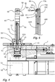
- FIG. 5 shows an application device 20 that represents the core component of a cavity preservation device 10.
- this application device 20 is provided for coupling to a robot arm 14 and, for this purpose, has a coupling device 24, which also includes supply and control lines, as will be explained below.
- the application device 20 has a rotary drive unit 30 with an in Fig. 1 Internal electric motor, not shown, which is provided to be able to rotate a rotatable rotor unit 50 about an axis of rotation 2.
- the electric motor 32 can not only rotate the rotor unit 50 to a limited extent between two end positions, but also freely through 360 ° and endlessly.
- the application device 20 has a mixing nozzle unit 60 which is attached to the rotor unit 50 in a rotationally fixed manner by means of a nut 58.
- the mixing nozzle unit 60 has an elongated shaft 66, the proximal end 60A of which is fixed by the nut 58.
- a mixing nozzle 80 is provided, which is aligned in the radial direction, so that fluid discharged here is discharged in a discharge direction that encloses an angle of approximately 90 ° with the axis of rotation 2.
- smaller angles can also be provided, for example 60 ° and more.
- connection 26 through which cavity preservatives, compressed air, electrical energy and control signals are transmitted.
- the 4 and 5 show the application device 20 and the mixing nozzle unit 60 in an enlarged and sectional illustration.
- the application device 20 is located in the area of the mixing nozzle unit 60 via the rotary drive unit 30, which only schematically shows in Fig. 4 includes electric motor 32 shown.
- This is provided for driving the rotor 50, which has a thread at its upper end, by means of which the nut 58 is screwed onto the rotor 50.
- the nut 58 has a conical inside corresponding to a likewise conical coupling device 62 on the side of the mixing nozzle unit 60.
- the rotor unit 50 is rotatably mounted on a base of the application device 20 by means of a roller bearing 52.
- the mixing nozzle unit 60 consists of three main components, namely an outer tube 64A, an inner tube 64B and a nozzle receptacle 64C, in which the mixing nozzle 80 is fastened.
- This design allows the mixing nozzle unit to be easily reconfigured by replacing components 64A, 64B with components of different lengths. As a result, mixing nozzle units with different maximum immersion depths can be used.
- a supply channel 70 for supplying the cavity preservative extends inside the inner tube 64B and continues into the component 64C. At its distal end, this feed channel 70 has a deflection 70A, at which incoming cavity preservative is deflected from an axial flow direction into a radial flow direction.
- a feed channel 72 is also created between the outside of the inner tube 64B and the inside of the outer tube 64A, which also continues into the component 64C and is deflected there in a deflection area 72A in the radial direction.
- Both fluids, the cavity preservative and gas used for atomization thus already diverted in the radial direction to the mixing nozzle 80, where in the case of the illustrated configuration of the mixing nozzle 80 they are directed to separate outlet openings 82, 84, at which they are released under pressure.
- the leaked cavity preservative 92 is atomized and forms a fine protective agent mist 96.
- the supply channels 70, 72 are supplied by the rotor unit 50, which for this purpose is also provided in the following 6 to 8 recognizable way has a central cavity preservative channel 54 and surrounding gas channels 56. As with the Fig. 4 , but especially the 7 and 8 It can be seen that rotary unions 43, 47 are provided, by means of which the channels 54, 56 are permanently connected to corresponding channels 42, 46 of the base. These channels 42, 46 are supplied by the aforementioned connections 26 on the coupling device 24, a switching valve 44 being provided in the channel 42 for the cavity preservative, by means of which the supply of cavity preservative is comparatively close to the discharge opening 84 can be interrupted.
- the valve 44 is provided as a pneumatically switchable valve.
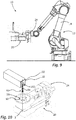
- Fig. 9 shows the intended main use of a spreading device according to the preceding figures.
- the application device 20 is attached with its coupling device 24 to a robot arm 14, by means of which the application device can be moved in flexible space, in particular in order to be moved relative to a vehicle chassis and to be brought into a working position.
- Fig. 10 shows such a working position.
- the mixing nozzle unit 60 is partially inserted through an opening 102 into a hollow body 100.
- the mixing nozzle unit 60 is rotated by means of the rotor unit 50 and the electric motor 32 as intended while simultaneously generating a protective agent mist.
- the spray 94 generated can therefore be applied in different directions and to all inner surfaces of the hollow body 100.
- Fig. 11 shows an orientation of the mixing nozzle in the direction of extension of the elongated hollow body 100. A particularly large amount of protective agent mist is required in this direction, since the inner surfaces arranged in this direction are comparatively large.
- Fig. 12 shows an orientation at 90 ° to that of Fig. 11 . In this orientation, the mixing nozzle is directed towards a relatively close wall, so that the surfaces to be coated in this angular range are smaller. A smaller amount of cavity preservative per angular unit is therefore also required.
- Fig. 13 shows an orientation in which no discharge of cavity preservative is desired.
- the valve 44 can remain open over the major part of a 360 ° rotation of the mixing nozzle unit 60 and only in the orientation of the Fig. 13 getting closed.
- the different amount of cavity preservative depending on the angle corresponding to the 11 and 12 it can be provided that, at a constant rotational speed of the mixing nozzle unit 60, the valve 44 or another electrically operated valve the flow of the cavity preservative in the angular position of the Fig. 12 towards the position of the Fig. 11 decreased.
- the speed of rotation of the mixing nozzle unit in the angular position of the Fig. 12 is considerably larger than in the angular position Fig. 11 be.
Landscapes
- Engineering & Computer Science (AREA)
- Robotics (AREA)
- Mechanical Engineering (AREA)
- Nozzles (AREA)
Abstract
Vorgeschlagen wird ein Verfahren zur Hohlraumkonservierung durch Aufbringung einer Schutzschicht (110) auf der Innenseite eines Hohlkörpers (100).A method for preserving the cavity by applying a protective layer (110) on the inside of a hollow body (100) is proposed.
Das Verfahren findet unter Verwendung einer Mischdüseneinheit statt, die mit einem proximalen Ende (60A) an einer Rotoreinheit (50) angekoppelt ist, mittels derer sie um eine Drehachse (2) drehbar ist und die über eine Mischdüse (80) verfügt. Die Mischdüseneinheit (60) verfügt über zwei getrennte und in Richtung der Drehachse (2) erstreckte Zuführkanäle (70, 72) für das Hohlraumkonservierungsmittel sowie für Gas zum Zwecke der Zerstäubung des Hohlraumkonservierungsmittels, durch die das Hohlraumkonservierungsmittel und das Zerstäubungsgas getrennt bis zur Mischdüse geleitet werden.The method takes place using a mixing nozzle unit which is coupled with a proximal end (60A) to a rotor unit (50), by means of which it can be rotated about an axis of rotation (2) and which has a mixing nozzle (80). The mixing nozzle unit (60) has two separate supply channels (70, 72), which extend in the direction of the axis of rotation (2), for the cavity preservative and for gas for the purpose of atomizing the cavity preservative, through which the cavity preservative and the atomizing gas are passed separately to the mixing nozzle .
Diese Mischdüseneinheit (60) wird in Richtung der Drehachse (2) durch eine Öffnung (102) des Hohlkörpers (100) in den Hohlkörper (100) eingefahren, so dass sich zumindest die Mischdüse (80) innerhalb des Hohlkörpers (200) befindet. Mittels der Mischdüse (80) wird das Hohlraumkonservierungsmittel dort in zerstäubter Form ausgetragen, wobei während des Austrags oder zwischen mehreren Austragsphasen die Mischdüseneinheit (60) um die Drehachse (2) gegenüber dem Hohlkörper (100) gedreht wird.


Description
Die Erfindung betrifft den Bereich der Hohlraumkonservierung, insbesondere den Bereich der Hohlraumkonservierung im Kfz-Bereich. Die Erfindung betrifft dabei ein Verfahren zur Ausbringung von Hohlraumkonservierungsmittel sowie dafür geeignete und vorgesehene Vorrichtungen.The invention relates to the area of cavity preservation, in particular the area of cavity preservation in the automotive field. The invention relates to a method for the application of cavity preservatives and devices suitable and intended therefor.
Solche Verfahren finden bei der Automobilherstellung seit Langem Verwendung. Um Hohlräume der Fahrzeugkarosserie gegen Umwelteinflüsse zu schützen und an Wandungen dieser Hohlräume beginnende Korrosionen zu verhindern, werden die Innenoberflächen solcher Hohlräume mit einem Hohlraumkonservierungsmittel überzogen. Die verfestigte Schicht erschwert Korrosion. Die fraglichen Hohlräume, bei denen diese Verfahren angewendet werden, sind insbesondere die Schweller, Hohlräume an den Radläufen sowie Längs- und Querträger des Fahrzeugs.Such processes have long been used in automobile manufacture. In order to protect cavities in the vehicle body against environmental influences and to prevent corrosion beginning on the walls of these cavities, the interior surfaces of such cavities are coated with a cavity preservative. The solidified layer makes corrosion more difficult. The cavities in question, in which these methods are used, are in particular the sills, cavities on the wheel arches and the longitudinal and cross members of the vehicle.
Aus der
Die Erfindung betrifft insbesondere den Bereich der Hohlraumkonservierung mittels eines solchen Schutzmittelnebels.The invention relates in particular to the area of cavity preservation by means of such a protective agent mist.
Aus der
Aufgabe der Erfindung ist es, ein Verfahren und die die hierfür geeignete Vorrichtung zur Verfügung zu stellen, um Hohlraumkonservierungsmittel insbesondere bei zerstäubter oder gar vernebelter Form derart auszubringen, dass sich eine hochqualitative Schicht mit gut beeinflussbarer Schichtdicke bildet.The object of the invention is to provide a method and the device suitable for this purpose, for cavity preservatives, in particular in the case of atomized or even atomized form to be applied in such a way that a high-quality layer with a layer thickness that can be influenced is formed.
Vorgeschlagen wird hierfür ein Verfahren zur Hohlraumkonservierung, welches die Aufbringung einer Schutzschicht aus einem Hohlraumkonservierungsmittel auf der Innenseite eines Hohlkörpers, insbesondere auf der Innenseite eines Kfz-Teils, ermöglicht. Dieses Verfahren findet vorzugsweise unter Verwendung einer erfindungsgemäßen Hohlraumkonservierungseinrichtung mit erfindungsgemäßer Mischdüseneinheit statt, so dass diese Aspekte der Erfindung im Weiteren gemeinsam mit dem Verfahren erläutert sind.For this purpose, a method for cavity preservation is proposed, which enables the application of a protective layer made of a cavity preservative on the inside of a hollow body, in particular on the inside of a motor vehicle part. This method preferably takes place using a cavity preservation device according to the invention with a mixing nozzle unit according to the invention, so that these aspects of the invention are explained below together with the method.
Das Verfahren erfolgt unter Nutzung einer Mischdüseneinheit, die mit einem proximalen Ende an einer Rotoreinheit angekoppelt ist, mittels derer sie um eine Drehachse drehbar ist, wobei die Mischdüseneinheit an einem distalen Ende über eine radial zur Drehachse ausgerichtete Mischdüse verfügt. Die drehbare Mischdüseneinheit verfügt dabei über zwei getrennte und in Richtung der Drehachse erstreckte Zuführkanäle für das Hohlraumkonservierungsmittel einerseits sowie für Gas zum Zwecke der Zerstäubung des Hohlraumkonservierungsmittels andererseits. Durch die Zuführkanäle können das Hohlraumkonservierungsmittel und das Zerstäubungsgas getrennt bis zur Mischdüse geleitet werden.The method is carried out using a mixing nozzle unit which is coupled with a proximal end to a rotor unit, by means of which it can be rotated about an axis of rotation, the mixing nozzle unit having a mixing nozzle oriented radially to the axis of rotation at a distal end. The rotatable mixing nozzle unit has two separate feed channels extending in the direction of the axis of rotation for the cavity preservative on the one hand and for gas for the purpose of atomizing the cavity preservative on the other. The cavity preservative and the atomizing gas can be passed separately through the feed channels to the mixing nozzle.
Im Rahmen des Verfahrens wird die Mischdüseneinheit in Richtung der Drehachse durch eine Öffnung des Hohlkörpers in diesen eingefahren, so dass sich zumindest die Mischdüse und eine oder mehrere an ihr vorgesehene Austragöffnungen innerhalb des Hohlkörpers befinden.In the context of the method, the mixing nozzle unit is moved into the axis of rotation through an opening in the hollow body, so that at least the mixing nozzle and one or more discharge openings provided on it are located within the hollow body.
Mittels der Mischdüse wird das Hohlraumkonservierungsmittel dann in zerstäubter Form ausgetragen und schlägt sich auf der Innenseite des Hohlkörpers nieder, wobei während des Austrags oder zwischen mehreren Austragsphasen die Mischdüseneinheit um die Drehachse gegenüber dem Hohlkörper gedreht wird.By means of the mixing nozzle, the cavity preservative is then discharged in an atomized form and is deposited on the inside of the hollow body, the mixing nozzle unit being rotated about the axis of rotation relative to the hollow body during the discharge or between several discharge phases.
Die genannte Mischdüse ist dabei für die Zerstäubung der getrennt zugeführten Fluide, also des flüssigen Hohlraumkonservierungsmittels und des gasförmigen Zerstäubungsmediums verantwortlich. Das gasförmige Medium ist vorzugsweise Luft. Soweit im Weiteren die Zerstäubung oder Vernebelung mit Luft genannt ist, umfasst dies auch die Verwendung anderer Gase. Das flüssige Hohlraumkonservierungsmittel und/oder das Gas werden der Mischdüse unter Überdruck zugeführt. Dabei können exemplarisch Drücke von 2 bar bis 10 bar für das Hohlraumkonservierungsmittel und auch 2 bar bis 10 bar für das Zerstäubungsgas genutzt werden.The aforementioned mixing nozzle is responsible for atomizing the separately supplied fluids, that is, the liquid cavity preservative and the gaseous atomizing medium. The gaseous medium is preferably air. To the extent that atomization or atomization with air is mentioned below, this also includes the use of other gases. The liquid cavity preservative and / or the gas are fed to the mixing nozzle under excess pressure. You can As an example, pressures from 2 bar to 10 bar can be used for the cavity preservative and also 2 bar to 10 bar for the atomizing gas.
Die Mischdüse kann eine interne Zerstäubungskammer aufweisen, aus der das mittels des Gases zerstäubte oder vernebelte Hohlraumkonservierungsmittel durch eine Austragöffnung ausgetragen wird. Besonders bevorzugt ist allerdings eine Gestaltung, bei der die Mischdüse für eine externe Vermengung von Luft und Hohlraumkonservierungsmittel und damit eine externe Zerstäubung oder Vernebelung vorgesehen ist. Sie weist in diesem Falle mindestens zwei Auslassöffnungen auf, die derart ausgerichtet sind, dass das austretende Hohlraumkonservierungsmittel bei gleichzeitig austretendem Gas stromabwärts der zwei Auslassöffnungen zerstäubt bzw. vernebelt wird.The mixing nozzle can have an internal atomization chamber, from which the cavity preservative atomized or atomized by means of the gas is discharged through a discharge opening. However, a design is particularly preferred in which the mixing nozzle is provided for external mixing of air and cavity preservative and thus external atomization or atomization. In this case, it has at least two outlet openings, which are oriented in such a way that the emerging cavity preservative is atomized or nebulized downstream of the two outlet openings with gas escaping at the same time.
Erfindungsgemäß wird die Mischdüse während des Austrags um die Drehachse gedreht, so dass sie ausgehend von einer Öffnung, durch die hindurch sie in den Hohlraum eingeführt ist, in unterschiedliche Richtungen Hohlraumkonservierungsmittel abgeben kann. Sie dreht sich während eines Beschichtungsvorgangs vorzugsweise mindestens um 360°, insbesondere vorzugsweise mehrfach. Wie im Weiteren noch erläutert ist, ist es daher von Vorteil, wenn die Fluidzuführung baulich ein endloses Drehen gestattet.According to the invention, the mixing nozzle is rotated about the axis of rotation during the discharge, so that it can release cavity preservative in different directions, starting from an opening through which it is introduced into the cavity. It preferably rotates at least 360 °, in particular preferably several times, during a coating process. As will be explained further below, it is therefore advantageous if the fluid supply allows an endless rotation in terms of construction.
Das Drehen der Mischdüse ist insbesondere von Vorteil, da sich gerade bei der Zerstäubung des Hohlraumkonservierungsmittels in Nebelform, also mit mittleren Tröpfchengrößen < 60 µm, vorzugsweise < 30 µm, insbesondere vorzugsweise < 10 µm, gezeigt hat, dass das Beschichtungsergebnis auch davon beeinflusst ist, wie groß der Schutzmittelnebelstrom ist, der in Richtung einer zu beschichtenden Fläche abgegeben wird. Die zyklische wiederholte Ausbringung eines vergleichsweise geringen Schutzmittelnebelstroms, die durch das mehrfache Drehen bei gleichzeitigem Austrag möglich wird, führt zu einer besseren Schutzschicht als die einmalige Ausbringung eines größeren Schutzmittelnebelstroms. Durch das wiederholte Drehen der Mischdüse lagert sich das Hohlraumkonservierungsmittel in homogenerer und reproduzierbarerer Weise ab. Vorzugsweise wird eine Drehgeschwindigkeit zwischen 1 und 10 Umdrehungen/Minute verwendet.Turning the mixing nozzle is particularly advantageous, since it has been shown that the atomization of the cavity preservative in fog form, that is to say with mean droplet sizes <60 µm, preferably <30 µm, particularly preferably <10 µm, also has an effect on the coating result. how large is the protective agent mist flow which is emitted in the direction of a surface to be coated. The cyclical repeated application of a comparatively low stream of protective agent mist, which is made possible by the multiple rotation with simultaneous discharge, leads to a better protective layer than the single application of a larger stream of protective agent mist. By repeatedly turning the mixing nozzle, the cavity preservative is deposited in a more homogeneous and reproducible manner. A rotational speed between 1 and 10 revolutions / minute is preferably used.
Auch wenn bei einem erfindungsgemäßen Verfahren ausschließlich die zerstäubte oder gar vernebelte Ausbringung des Hohlraumkonservierungsmittels vorgesehen ist, ist die Mischdüse vorzugsweise auch für die Abgabe eines unzerstäubten Strahls von Hohlraumkonservierungsmittel geeignet. Sie kann daher beispielsweise auch der gezielten Beschichtung von Schweißnähten im Hohlraum dienen. Auch in Hinblick auf die unzerstäubte Ausbringung ist die oben bereits genannte externe Zerstäubung durch die Mischdüse von Vorteil, da hier durch eine Unterbrechung der Gaszufuhr der gewünschte Strahl erzeugbar ist.Even if only the atomized or even nebulized application of the cavity preservative is provided in a method according to the invention, the mixing nozzle is preferably also suitable for delivering an unsprayed jet of cavity preservative. It can therefore also be used for the targeted coating of weld seams in the cavity, for example. The above-mentioned external atomization through the mixing nozzle is also advantageous with regard to the unsprayed application, since the desired jet can be generated here by interrupting the gas supply.
Das genannte Verfahren kann grundsätzlich mit konstantem und ununterbrochenem Hohlraumkonservierungsmittelstrom bei gleichbleibender Drehgeschwindigkeit der Mischdüse betrieben werden. Es ist jedoch in der Praxis vorteilhaft, einen Austrag vorzusehen, der in Abhängigkeit der Winkelstellung variiert, so dass nicht in alle Richtungen die gleiche Menge des Hohlraumkonservierungsmittelstrom abgegeben werden.The above-mentioned method can in principle be operated with a constant and uninterrupted cavity preservative flow with a constant rotational speed of the mixing nozzle. In practice, however, it is advantageous to provide a discharge which varies as a function of the angular position, so that the same amount of the cavity preservative stream is not dispensed in all directions.
Es hat sich gezeigt, dass dies auch insbesondere bei der Erzeugung eines Schutzmittelnebels von Vorteil ist. Zwar bildet dieser zunächst eine Wolke aus Tröpfchen, die sich erst nach und nach niederschlagen und dadurch ohnehin zur Homogenisierung neigen. Es hat sich jedoch gezeigt, dass eine solche Nebelwolke dennoch lokal zu unterschiedlichen Schichtdicken führt. Durch einen variierenden Austrag in Abhängigkeit der Winkelstellung kann dem gezielt entgegengewirkt werden oder dies gegebenenfalls sogar gezielt eingesetzt werden, um lokal größere Schichtdicken zu erzeugen.It has been shown that this is also particularly advantageous when generating a protective agent mist. It initially forms a cloud of droplets, which gradually settle down and therefore tend to homogenize anyway. However, it has been shown that such a cloud of fog still leads locally to different layer thicknesses. By varying the discharge depending on the angular position, this can be counteracted in a targeted manner or this can even be used in a targeted manner in order to produce locally larger layer thicknesses.
Verschiedene Arten der richtungsabhängigen Variation sowie Kombinationen hieraus sind möglich.Different types of direction-dependent variation and combinations thereof are possible.
Bei einer Variante ist vorgesehen, dass während des Drehens der Mischdüseneinheit die Zufuhr von Hohlraumkonservierungsmittel zur Mischdüse variiert. Dies führt bei einer Drehbewegung der Mischdüseneinheit mit konstanter Drehgeschwindigkeit zum genannten variierenden Austrag je überstrichenem Winkelbereich. Die Variation des zugeführten Hohlraumkonservierungsmittels kann insbesondere über ein elektrisch gesteuertes Dosierventil erfolgen.In one variant, it is provided that the supply of cavity preservative to the mixing nozzle varies while the mixing nozzle unit is rotating. When the mixing nozzle unit rotates at a constant rotational speed, this leads to the aforementioned varying discharge per swept angular range. The supplied cavity preservative can be varied in particular via an electrically controlled metering valve.
Eine besonders einfache Art der Variation liegt vor, wenn ein Ventil vorgesehen ist, welches während der Durchführung des Verfahrens lediglich die Zufuhr von Hohlraumkonservierungsmittel phasenweise aktiviert und phasenweise deaktiviert. Hierfür ist ein einfaches Ventil, insbesondere ein pneumatisch gesteuertes Ventil, ausreichend. Die Deaktivierung des Austrags während der Drehbewegung der Mischdüse kann insbesondere zweckmäßig sein, wenn in einem Winkelbereich keinerlei Austrag erfolgen soll, beispielsweise da dort Öffnungen vorgesehen sind, durch die der Schutzmittelnebel oder - sprühstrahl anderenfalls ungewollt austreten würde.A particularly simple type of variation is provided if a valve is provided which only activates and deactivates the supply of cavity preservative in phases during the implementation of the method. A simple valve, in particular a pneumatically controlled valve, is sufficient for this. Deactivating the discharge during the rotary movement of the mixing nozzle can be particularly expedient if no discharge is to take place in an angular range, for example because there are openings through which the protective agent mist or spray jet would otherwise escape unintentionally.
Besonders vorteilhaft ist es, wenn der winkelabhängige Hohlraumkonservierungsmittelstrom dadurch erzielt wird, dass die Drehgeschwindigkeit variiert wird. In unterschiedlichen Winkelbereichen führt ein konstanter Hohlraumkonservierungsmittelstrom dann zu einer variierenden Menge Hohlraumkonservierungsmittel je Winkelbereich. Ein solches Verfahren ist mit einem einfach schaltenden Ventil oder ggf. sogar ohne Ventil im Zuführkanal des Hohlraumkonservierungsmittels möglich, alleine durch die Ansteuerung des vorzugsweise elektrischen Motors, mittels dessen die Mischdüse gedreht wird.It is particularly advantageous if the angle-dependent cavity preservative flow is achieved by varying the speed of rotation. In different angular ranges, a constant cavity preservative flow then leads to a varying amount of cavity preservative per angular range. Such a method is possible with a simple switching valve or possibly even without a valve in the feed channel of the cavity preservative, simply by actuating the preferably electric motor, by means of which the mixing nozzle is rotated.
Die Mischdüseneinheit, die für das beschriebene Verfahren vorzugsweise verwendet wird, verfügt über einen länglichen Schaft, an dessen proximalen Ende eine Kopplungseinrichtung zur Anbringung an einer Rotoreinheit vorgesehen ist und der sich entlang einer durch die Kopplungseinrichtung definierten Drehachse erstreckt. Diese Mischdüseneinheit verfügt im Bereich eines distalen Endes über die Mischdüse, die quer zur Drehachse ausgerichtet ist, so dass das zerstäubte Hohlraumkonservierungsmittel bezogen auf die Drehrichtung in radialer Austragrichtung mittels der Mischdüse abgegeben werden kann.The mixing nozzle unit, which is preferably used for the described method, has an elongated shaft, at the proximal end of which a coupling device is provided for attachment to a rotor unit and which extends along an axis of rotation defined by the coupling device. In the area of a distal end, this mixing nozzle unit has the mixing nozzle, which is oriented transversely to the axis of rotation, so that the atomized cavity preservative can be dispensed in the radial discharge direction by means of the mixing nozzle in relation to the direction of rotation.
Dabei verfügt die Mischdüseneinheit über zwei getrennte und in Richtung der Drehachse erstreckte Zuführkanäle für das Hohlraumkonservierungsmittel sowie für Gas zum Zwecke der Zerstäubung, durch die das Hohlraumkonservierungsmittel und das Zerstäubungsgas getrennt bis zur Mischdüse geleitet werden. Hierdurch wird der Bedarf einer frühen Zerstäubung im nicht drehbaren Teil der Hohlraumkonservierungseinrichtung vermieden. Dies ist erheblich, da insbesondere bei einer sehr feinen Zerstäubung bzw. einer Vernebelung die Zuführung des zerstäubten oder vernebelten Hohlraumkonservierungsmittels bis zu einer Austragöffnung die Gefahr von Funktionsstörungen mit sich bringt, wenn sich das zerstäubte Hohlraumkonservierungsmittel auf Wandungen der Zuführkanäle niederschlägt.The mixing nozzle unit has two separate and extending in the direction of the axis of rotation feed channels for the cavity preservative and for gas for atomization, through which the cavity preservative and the atomizing gas are passed separately to the mixing nozzle. This avoids the need for early atomization in the non-rotatable part of the cavity preservation device. This is significant since, in particular in the case of very fine atomization or atomization, the supply of the atomized or atomized cavity preservative up to a discharge opening entails the risk of malfunctions if the atomized cavity preservative is deposited on the walls of the feed channels.
Es ist daher bei einer erfindungsgemäßen Mischdüseneinheit vorgesehen, dass die getrennten Zuführkanäle Umlenkungsabschnitte aufweisen, in denen das zugeführte Hohlraumkonservierungsmittel und das zugeführte Gas von einer axialen Strömungsrichtung zum Zwecke der nachfolgenden Zerstäubung getrennt voneinander in eine radiale Strömungsrichtung umgelenkt werden. Erst jenseits dieser Umlenkung erfolgen die Vermengung und dadurch die Zerstäubung des Hohlraumkonservierungsmittels. Wie oben schon genannt, kann dies in einer internen Misch- und Zerstäubungskammer oder extern geschehen.It is therefore provided in a mixing nozzle unit according to the invention that the separate feed channels have deflection sections in which the cavity preservative and the gas supplied are diverted from one another in an axial direction of flow for the purpose of subsequent atomization in a radial direction of flow. Only beyond this redirection does the mixing and thus the atomization of the cavity preservative take place. As mentioned above, this can be done in an internal mixing and atomizing chamber or externally.
Die beiden Zuführkanäle münden hierfür insbesondere vorzugsweise in den genannten vorzugsweise mindestens zwei Auslassöffnungen, von denen eine mit dem Zuführkanal für Gas verbunden ist und von denen die andere mit dem Zuführkanal für Hohlraumkonservierungsmittel verbunden ist. Insbesondere vorzugsweise ist die Auslassöffnung für das Hohlraumkonservierungsmittel zentrisch angeordnet und wird von der Gas-Auslassöffnung oder den Gas-Auslassöffnungen umgeben. Insbesondere kann es sich um eine Gas-Auslassöffnung handeln, die ringförmig die Auslassöffnung für das Hohlraumkonservierungsmittel umgibt.For this purpose, the two feed channels in particular preferably open into the above-mentioned preferably at least two outlet openings, one of which is connected to the feed channel for gas and the other of which is connected to the feed channel for cavity preservative. The outlet opening for the cavity preservative is particularly preferably arranged centrally and is surrounded by the gas outlet opening or the gas outlet openings. In particular, it can be a gas outlet opening that surrounds the outlet opening for the cavity preservative in a ring shape.
Die Mischdüseneinheit ist insbesondere vorzugsweise modular ausgebildet, so dass sie mindestens zwei voneinander einfach trennbare Teile aufweist, von denen das eine die Kopplungseinrichtung zur Befestigung an der Rotoreinheit sowie vorzugsweise den überwiegenden Teil des Schaftes bildet, während das andere Teil mindestens die Mischdüse umfasst. Eine solche Bauweise gestattet es, die vergleichsweise aufwändige und teure Mischdüse in unterschiedlichen Konfigurationen und insbesondere mit Schäften unterschiedlicher Länge und damit unterschiedlicher maximaler Eintauchtiefe zu verwenden.The mixing nozzle unit is particularly preferably of modular design, so that it has at least two parts that are easily separable from one another, one of which forms the coupling device for attachment to the rotor unit and preferably the major part of the shaft, while the other part comprises at least the mixing nozzle. Such a design allows the comparatively complex and expensive mixing nozzle to be used in different configurations and in particular with shafts of different lengths and thus different maximum immersion depths.
Um die Handhabung einer erfindungsgemäßen Mischdüseneinheit zu erleichtern, weist diese vorzugsweise am proximalen Ende eine Ausrichtungsmarkierung auf, so dass auch bei partiell in die Öffnung des Hohlkörpers eingefahrener Mischdüseneinheit die Ausrichtung der Mischdüse von außen erkennbar ist. Ebenfalls zum Zwecke der erleichterten Handhabung ist es von Vorteil, wenn die Mischdüseneinheit entlang ihres länglichen Schaftes eine Skala oder Markierungen aufweist, so dass eine Eintauchtiefe der Mischdüseneinheit in den Hohlkörper von außen erkennbar ist.In order to facilitate the handling of a mixing nozzle unit according to the invention, it preferably has an alignment mark at the proximal end, so that the orientation of the mixing nozzle can be seen from the outside even when the mixing nozzle unit is partially inserted into the opening of the hollow body. Also for the purpose of easier handling, it is advantageous if the mixing nozzle unit has a scale or markings along its elongated shaft, so that an immersion depth of the mixing nozzle unit in the hollow body can be seen from the outside.
Die Erfindung betrifft neben der Mischdüseneinheit als solcher auch eine Hohlraumkonservierungseinrichtung zur Aufbringung einer Schutzschicht aus einem Hohlraumkonservierungsmittel auf der Innenseite eines Hohlkörpers. Diese Hohlraumkonservierungseinrichtung verfügt über eine Ausbringungseinrichtung mit einer um eine Drehachse drehbaren Rotoreinheit. Diese Rotoreinheit weist eine Kopplungseinrichtung zur Ankoppelung einer Mischdüseneinheit der beschriebenen Art auf.In addition to the mixing nozzle unit as such, the invention also relates to a cavity preservation device for applying a protective layer made of a cavity preservative on the inside of a hollow body. This cavity preservation device has an application device with a rotor unit rotatable about an axis of rotation. This rotor unit has a coupling device for coupling a mixing nozzle unit of the type described.
Die genannte Ausbringungseinrichtung, an der die Mischdüseneinheit drehbar befestigt ist, umfasst Kanäle zur Zuführung von Gas und Hohlraumkonservierungsmittel. Sie umfasst vorzugsweise weiterhin einen Motor zum Antrieb der Rotoreinheit, an der die Mischdüseneinheit wechselbar befestigt ist. Die Ausbringungseinrichtung ist vorzugsweise dafür vorgesehen, am Roboterarm eines Roboters befestigt zu werden und weist zu diesem Zweck eine hierfür vorgesehen Kopplungseinrichtung auf. Diese ist vorzugsweise derart gestaltet, dass auch die Zufuhrkanäle für Gas und/oder für Hohlraumkonservierungsmittel und/oder Steuerleitungen zur pneumatischen oder elektrischen Versorgung eines Auslassventils oder eines Elektromotors zum Antrieb der Rotoreinheit durch Ankopplung der Ausbringungseinheit verbunden werden.The said delivery device, on which the mixing nozzle unit is rotatably fastened, comprises channels for supplying gas and cavity preservative. It preferably further comprises a motor for driving the rotor unit, to which the mixing nozzle unit is exchangeably attached. The application device is preferably intended to be attached to the robot arm of a robot and has a coupling device provided for this purpose. This is preferably designed in such a way that the supply channels for gas and / or for cavity preservatives and / or control lines for the pneumatic or electrical supply to an outlet valve or an electric motor for driving the rotor unit are connected by coupling the application unit.
Die Ausbringungseinrichtung umfasst demzufolge vorzugsweise mindestens ein Ventil, welches zur Steuerung insbesondere der Zufuhr von Hohlraumkonservierungsmittel zum Mischdüseneinheit dient. Wie bereits erläutert, kann es sich um ein Ventil handeln, welches lediglich das Öffnen und Schließen des Zuführkanals gestattet, oder um ein Dosierventil, welches entweder mehrere diskrete Öffnungszustände oder als Stetigventil beliebige Öffnungszustände gestattet.The application device accordingly preferably comprises at least one valve which serves to control, in particular, the supply of cavity preservative to the mixing nozzle unit. As already explained, it can be a valve which only allows the opening and closing of the feed channel, or a metering valve which either allows several discrete opening states or any opening states as a continuous valve.
Die Ausbringungseinrichtung umfasst weiterhin vorzugsweise den genannten Motor, insbesondere in Form eines Elektromotors. Sofern dieser in oben genannter Weise mit variabler Geschwindigkeit betrieben werden soll, so erfolgt eine dahingehende Steuerung vorzugsweise durch eine zentrale Steuerung des Roboters, an dessen Arm die Ausbringungseinrichtung angebracht ist.The application device further preferably comprises the motor mentioned, in particular in the form of an electric motor. If this is to be operated at a variable speed in the manner mentioned above, this control is preferably carried out by a central control of the robot, on the arm of which the application device is attached.
Weitere Vorteile und Aspekte der Erfindung ergeben sich aus den Ansprüchen und aus der nachfolgenden Beschreibung von bevorzugten Ausführungsbeispielen der Erfindung, die nachfolgend anhand der Figuren erläutert sind.
-
Fig. 1 bis 3 zeigen eine erfindungsgemäße Ausbringungseinrichtung mit erfindungsgemäßer Mischdüseneinheit in verschiedenen Perspektiven. -
Fig. 4 und 5 zeigen die Ausbringungseinrichtung der vorstehenden Figuren in teilgeschnittener bzw. geschnittener Darstellung. -
Fig. 6 bis 8 zeigen weitere Schnitte, aus denen die Fluidzuführung zur Mischdüseneinheit zu ersehen ist. -
Fig. 9 zeigt eine Hohlraumkonservierungseinrichtung mit einem Roboter zur Handhabung der Ausbringungseinrichtung. -
Fig. 10 verdeutlicht die Funktionsweise der Ausbringungseinrichtung im Betrieb. -
Fig. 11 bis 13 zeigen einen drehwinkelabhängig variablen Austrag von Hohlraumkonservierungsmittel.
-
1 to 3 show an application device according to the invention with a mixing nozzle unit according to the invention in different perspectives. -
4 and 5 show the application device of the preceding figures in a partially cut or cut view. -
6 to 8 show further sections from which the fluid supply to the mixing nozzle unit can be seen. -
Fig. 9 shows a cavity preservation device with a robot for handling the application device. -
Fig. 10 illustrates the operation of the application device in operation. -
11 to 13 show a variable discharge of cavity preservative depending on the angle of rotation.
Die Ausbringungseinrichtung 20 verfügt über eine Drehantriebseinheit 30 mit einem in
Zum Zwecke der Ausbringung von Hohlraumkonservierungsmittel verfügt die Ausbringungseinrichtung 20 über eine Mischdüseneinheit 60, die mittels einer Mutter 58 drehfest an der Rotoreinheit 50 angebracht ist. Die Mischdüseneinheit 60 weist einen länglichen Schaft 66 auf, dessen proximales Ende 60A durch die Mutter 58 festgelegt ist. Am distalen Ende 60B der Mischdüseneinheit 60 ist eine Mischdüse 80 vorgesehen, die in radialer Richtung ausgerichtet ist, so dass hier ausgetragenes Fluid in einer Austragsrichtung ausgetragen wird, die zur Drehachse 2 etwa einen Winkel von 90° einschließt. Je nach Anwendungszweck können auch geringere Winkel vorgesehen sein, beispielsweise 60° und mehr.For the purpose of applying cavity preservative, the
Bezugnehmend auf
Die
Die Mischdüseneinheit 60 besteht neben der Mischdüse 80 selbst aus drei Hauptbestandteilen, nämlich einem Außenrohr 64A, einem Innenrohr 64B und einer Düsenaufnahme 64C, in der die Mischdüse 80 befestigt ist. Diese Bauweise gestattet ein einfaches Umkonfigurieren der Mischdüseneinheit, indem die Bauteile 64A, 64B gegen Bauteile anderer Länge ausgetauscht werden. Hierdurch lassen sich Mischdüseneinheiten mit verschiedener maximaler Eintauchtiefe nutzen. Innerhalb des Innenrohrs 64B und fortgesetzt bis in das Bauteil 64C erstreckt sich ein Zuführkanal 70 zur Zuführung des Hohlraumkonservierungsmittels. An seinem distalen Ende weist dieser Zuführkanal 70 eine Umlenkung 70A auf, an der zuströmendes Hohlraumkonservierungsmittel aus einer axialen Strömungsrichtung in eine radiale Strömungsrichtung umgelenkt wird. In ähnlicher Weise ist auch ein Zuführkanal 72 zwischen der Außenseite des Innenrohrs 64B und der Innenseite des Außenrohrs 64A geschaffen, der sich ebenfalls bis ins Bauteil 64C fortsetzt und dort in einem Umlenkungsbereich 72A in radiale Richtung umgelenkt wird. Beide Fluide, das Hohlraumkonservierungsmittel sowie zur Zerstäubung verwendetes Gas, gelangen also bereits in radiale Richtung umgelenkt zur Mischdüse 80, wo sie im Falle der dargestellten Ausgestaltung der Mischdüse 80 zu getrennten Auslassöffnungen 82, 84 geleitet werden, an denen sie unter Druck abgegeben werden. Wie durch die Pfeile 94 verdeutlicht ist, wird das ausgetretene Hohlraumkonservierungsmittel 92 dabei zerstäubt und bildet einen feinen Schutzmittelnebel 96.In addition to the mixing
Die Versorgung der genannten Zuführkanäle 70, 72 erfolgt durch die Rotoreinheit 50, die zu diesem Zweck in der auch den folgenden
Die
Um dieses Ergebnis zu erzielen sind mehrere Möglichkeiten gegeben. So kann bei einer Variante des Verfahrens das Ventil 44 über den überwiegenden Teil einer 360°-Drehung der Mischdüseneinheit 60 geöffnet bleiben und nur in der Ausrichtung der
Claims (14)
Priority Applications (5)
| Application Number | Priority Date | Filing Date | Title |
|---|---|---|---|
| EP18213643.2A EP3670001B1 (en) | 2018-12-18 | 2018-12-18 | Method for cavity preservation, mixing nozzle unit and cavity preservation device with such a mixing nozzle unit |
| MX2021007333A MX2021007333A (en) | 2018-12-18 | 2019-11-06 | Method for preserving cavities, mixing nozzle unit and cavity-preserving device having a mixing nozzle unit of this type. |
| CN201980084370.9A CN113242769A (en) | 2018-12-18 | 2019-11-06 | Method for preserving a cavity, mixing nozzle unit and cavity preserving device having such a mixing nozzle unit |
| US17/415,320 US12311395B2 (en) | 2018-12-18 | 2019-11-06 | Method for preserving cavities, mixing nozzle unit and cavity-preserving device having a mixing nozzle unit of this type |
| PCT/EP2019/080438 WO2020126199A1 (en) | 2018-12-18 | 2019-11-06 | Method for preserving cavities, mixing nozzle unit and cavity-preserving device having a mixing nozzle unit of this type |
Applications Claiming Priority (1)
| Application Number | Priority Date | Filing Date | Title |
|---|---|---|---|
| EP18213643.2A EP3670001B1 (en) | 2018-12-18 | 2018-12-18 | Method for cavity preservation, mixing nozzle unit and cavity preservation device with such a mixing nozzle unit |
Publications (2)
| Publication Number | Publication Date |
|---|---|
| EP3670001A1 true EP3670001A1 (en) | 2020-06-24 |
| EP3670001B1 EP3670001B1 (en) | 2021-07-28 |
Family
ID=64745946
Family Applications (1)
| Application Number | Title | Priority Date | Filing Date |
|---|---|---|---|
| EP18213643.2A Active EP3670001B1 (en) | 2018-12-18 | 2018-12-18 | Method for cavity preservation, mixing nozzle unit and cavity preservation device with such a mixing nozzle unit |
Country Status (5)
| Country | Link |
|---|---|
| US (1) | US12311395B2 (en) |
| EP (1) | EP3670001B1 (en) |
| CN (1) | CN113242769A (en) |
| MX (1) | MX2021007333A (en) |
| WO (1) | WO2020126199A1 (en) |
Citations (7)
| Publication number | Priority date | Publication date | Assignee | Title |
|---|---|---|---|---|
| JPH06206025A (en) * | 1993-01-07 | 1994-07-26 | Toyota Motor Corp | Rotating type inner face flame spray apparatus |
| US6206300B1 (en) * | 1999-07-30 | 2001-03-27 | Curtis Dyna-Fog, Lyd. | Aerosol generator |
| US6632475B1 (en) * | 2000-10-06 | 2003-10-14 | Nicola Bleggi | Method of lining underground pipes and apparatus for performing the method |
| JP3699770B2 (en) * | 1996-02-21 | 2005-09-28 | ユーキャン株式会社 | Spraying equipment |
| DE102010034921A1 (en) | 2010-08-20 | 2012-02-23 | Dürr Systems GmbH | Nozzle for application of a coating agent |
| FR3014334A3 (en) * | 2013-12-05 | 2015-06-12 | Renault Sa | NOZZLE OF A PLATE OF INJECTION OF WAX |
| WO2017013620A1 (en) | 2015-07-21 | 2017-01-26 | Readynovation | Connecting device for straps, objects or parts of clothes and accessories |
Family Cites Families (12)
| Publication number | Priority date | Publication date | Assignee | Title |
|---|---|---|---|---|
| US3120346A (en) * | 1962-10-31 | 1964-02-04 | American Mach & Foundry | Rotary spray devices |
| JPS56161870A (en) * | 1980-05-14 | 1981-12-12 | Sumitomo Light Metal Ind Ltd | Method and apparatus for coating long pipe having small diameter |
| JP4245553B2 (en) | 2004-11-26 | 2009-03-25 | Lui株式会社 | Mold release agent applicator |
| US8480011B2 (en) * | 2007-09-04 | 2013-07-09 | Dehn's Innovations, Llc | Nozzle system and method |
| DE102009001396B4 (en) | 2009-03-09 | 2013-09-05 | Albrecht von Linde | sprayer |
| EP2286925B1 (en) | 2009-08-20 | 2018-03-14 | Sulzer Mixpac AG | Static spray mixer |
| CN202539010U (en) | 2012-02-15 | 2012-11-21 | 常州市璟胜自动化科技有限公司 | Backwashing device for spraying machine |
| DK2730345T3 (en) | 2012-11-08 | 2016-10-24 | Alfa Laval Corp Ab | Fluid system with exhaust nozzle with two outputs |
| BR112016019167B1 (en) | 2014-02-19 | 2020-10-20 | Ant Applied New Technologies Ag | nozzle head |
| US9500463B2 (en) | 2014-07-29 | 2016-11-22 | Caterpillar Inc. | Rotating bore sprayer alignment indicator assembly |
| EP3205407B1 (en) * | 2016-02-09 | 2019-09-25 | IPR-Intelligente Peripherien für Roboter GmbH | Method and installation for covering internal walls of a cavity with a protective layer made of corrosion protecting wax |
| CN206305409U (en) | 2016-12-06 | 2017-07-07 | 东莞市耀星机器人科技有限公司 | Spray Apparatus and Spray Equipment |
-
2018
- 2018-12-18 EP EP18213643.2A patent/EP3670001B1/en active Active
-
2019
- 2019-11-06 US US17/415,320 patent/US12311395B2/en active Active
- 2019-11-06 WO PCT/EP2019/080438 patent/WO2020126199A1/en active IP Right Grant
- 2019-11-06 CN CN201980084370.9A patent/CN113242769A/en active Pending
- 2019-11-06 MX MX2021007333A patent/MX2021007333A/en unknown
Patent Citations (7)
| Publication number | Priority date | Publication date | Assignee | Title |
|---|---|---|---|---|
| JPH06206025A (en) * | 1993-01-07 | 1994-07-26 | Toyota Motor Corp | Rotating type inner face flame spray apparatus |
| JP3699770B2 (en) * | 1996-02-21 | 2005-09-28 | ユーキャン株式会社 | Spraying equipment |
| US6206300B1 (en) * | 1999-07-30 | 2001-03-27 | Curtis Dyna-Fog, Lyd. | Aerosol generator |
| US6632475B1 (en) * | 2000-10-06 | 2003-10-14 | Nicola Bleggi | Method of lining underground pipes and apparatus for performing the method |
| DE102010034921A1 (en) | 2010-08-20 | 2012-02-23 | Dürr Systems GmbH | Nozzle for application of a coating agent |
| FR3014334A3 (en) * | 2013-12-05 | 2015-06-12 | Renault Sa | NOZZLE OF A PLATE OF INJECTION OF WAX |
| WO2017013620A1 (en) | 2015-07-21 | 2017-01-26 | Readynovation | Connecting device for straps, objects or parts of clothes and accessories |
Also Published As
| Publication number | Publication date |
|---|---|
| CN113242769A (en) | 2021-08-10 |
| MX2021007333A (en) | 2021-09-30 |
| US20220062937A1 (en) | 2022-03-03 |
| WO2020126199A1 (en) | 2020-06-25 |
| US12311395B2 (en) | 2025-05-27 |
| EP3670001B1 (en) | 2021-07-28 |
Similar Documents
| Publication | Publication Date | Title |
|---|---|---|
| EP1351009B1 (en) | Device and process for lining a pipe | |
| EP2605859B1 (en) | Nozzle for applying a coating agent | |
| EP2451586B1 (en) | Paint spray gun | |
| EP1912745B1 (en) | Method for spraying on pigmented liquids | |
| EP2704850B1 (en) | Spray painting device | |
| EP1340550A2 (en) | Spray gun | |
| WO2008125209A1 (en) | Device for spraying pigmented fluids | |
| EP2228136B1 (en) | Jet device | |
| DE69724400T2 (en) | Device with controlled delivery pattern | |
| WO2016066244A1 (en) | Applicator for applying an application material | |
| EP3113887B1 (en) | Extension device for spraying devices and spraying device | |
| EP2485848B1 (en) | Nozzle | |
| DE3151929C2 (en) | Device for the successive application of different coating liquids | |
| EP3670001B1 (en) | Method for cavity preservation, mixing nozzle unit and cavity preservation device with such a mixing nozzle unit | |
| DE2757522C2 (en) | Round or ring jet nozzle for generating and blasting a mist or aerosol for coating objects | |
| DE102016001188A1 (en) | Applicator for application of a job material | |
| DE4115395C2 (en) | ||
| DE9206410U1 (en) | Spraying device for the inner walls of hollow bodies | |
| WO2017008887A1 (en) | Coating agent valve | |
| DE102006056230A1 (en) | Hollow body internal coating device, has spray head positioned in inner side of hollow body in decentralized manner, such that distance between nozzle and surface of hollow body is adjusted, where body is rotatable around longitudinal axis | |
| CH654760A5 (en) | SPRAY NOZZLE. | |
| DE903460C (en) | Dusting device for printed sheets | |
| DE10209485B4 (en) | Device for internal coating of a pipe | |
| DE202015009893U1 (en) | Robotic tool and robot for dispensing an anti-corrosion wax | |
| WO1983003129A1 (en) | Dosing valve for aerosol container |
Legal Events
| Date | Code | Title | Description |
|---|---|---|---|
| PUAI | Public reference made under article 153(3) epc to a published international application that has entered the european phase |
Free format text: ORIGINAL CODE: 0009012 |
|
| STAA | Information on the status of an ep patent application or granted ep patent |
Free format text: STATUS: THE APPLICATION HAS BEEN PUBLISHED |
|
| AK | Designated contracting states |
Kind code of ref document: A1 Designated state(s): AL AT BE BG CH CY CZ DE DK EE ES FI FR GB GR HR HU IE IS IT LI LT LU LV MC MK MT NL NO PL PT RO RS SE SI SK SM TR |
|
| AX | Request for extension of the european patent |
Extension state: BA ME |
|
| STAA | Information on the status of an ep patent application or granted ep patent |
Free format text: STATUS: REQUEST FOR EXAMINATION WAS MADE |
|
| 17P | Request for examination filed |
Effective date: 20200911 |
|
| RBV | Designated contracting states (corrected) |
Designated state(s): AL AT BE BG CH CY CZ DE DK EE ES FI FR GB GR HR HU IE IS IT LI LT LU LV MC MK MT NL NO PL PT RO RS SE SI SK SM TR |
|
| RIC1 | Information provided on ipc code assigned before grant |
Ipc: B05B 15/68 20180101ALI20210128BHEP Ipc: B05B 13/06 20060101ALI20210128BHEP Ipc: B05B 15/652 20180101ALI20210128BHEP Ipc: B05B 7/06 20060101ALN20210128BHEP Ipc: B05B 13/04 20060101AFI20210128BHEP Ipc: B05B 12/12 20060101ALI20210128BHEP Ipc: B25J 11/00 20060101ALI20210128BHEP Ipc: B05B 3/02 20060101ALN20210128BHEP |
|
| GRAP | Despatch of communication of intention to grant a patent |
Free format text: ORIGINAL CODE: EPIDOSNIGR1 |
|
| STAA | Information on the status of an ep patent application or granted ep patent |
Free format text: STATUS: GRANT OF PATENT IS INTENDED |
|
| RIC1 | Information provided on ipc code assigned before grant |
Ipc: B05B 15/68 20180101ALI20210301BHEP Ipc: B05B 12/12 20060101ALI20210301BHEP Ipc: B05B 3/02 20060101ALN20210301BHEP Ipc: B25J 11/00 20060101ALI20210301BHEP Ipc: B05B 7/06 20060101ALN20210301BHEP Ipc: B05B 15/652 20180101ALI20210301BHEP Ipc: B05B 13/06 20060101ALI20210301BHEP Ipc: B05B 13/04 20060101AFI20210301BHEP |
|
| INTG | Intention to grant announced |
Effective date: 20210317 |
|
| GRAS | Grant fee paid |
Free format text: ORIGINAL CODE: EPIDOSNIGR3 |
|
| GRAA | (expected) grant |
Free format text: ORIGINAL CODE: 0009210 |
|
| STAA | Information on the status of an ep patent application or granted ep patent |
Free format text: STATUS: THE PATENT HAS BEEN GRANTED |
|
| AK | Designated contracting states |
Kind code of ref document: B1 Designated state(s): AL AT BE BG CH CY CZ DE DK EE ES FI FR GB GR HR HU IE IS IT LI LT LU LV MC MK MT NL NO PL PT RO RS SE SI SK SM TR |
|
| REG | Reference to a national code |
Ref country code: GB Ref legal event code: FG4D Free format text: NOT ENGLISH |
|
| REG | Reference to a national code |
Ref country code: CH Ref legal event code: EP |
|
| REG | Reference to a national code |
Ref country code: DE Ref legal event code: R096 Ref document number: 502018006298 Country of ref document: DE |
|
| REG | Reference to a national code |
Ref country code: AT Ref legal event code: REF Ref document number: 1414236 Country of ref document: AT Kind code of ref document: T Effective date: 20210815 |
|
| REG | Reference to a national code |
Ref country code: IE Ref legal event code: FG4D Free format text: LANGUAGE OF EP DOCUMENT: GERMAN |
|
| REG | Reference to a national code |
Ref country code: LT Ref legal event code: MG9D |
|
| REG | Reference to a national code |
Ref country code: NL Ref legal event code: MP Effective date: 20210728 |
|
| PG25 | Lapsed in a contracting state [announced via postgrant information from national office to epo] |
Ref country code: HR Free format text: LAPSE BECAUSE OF FAILURE TO SUBMIT A TRANSLATION OF THE DESCRIPTION OR TO PAY THE FEE WITHIN THE PRESCRIBED TIME-LIMIT Effective date: 20210728 Ref country code: ES Free format text: LAPSE BECAUSE OF FAILURE TO SUBMIT A TRANSLATION OF THE DESCRIPTION OR TO PAY THE FEE WITHIN THE PRESCRIBED TIME-LIMIT Effective date: 20210728 Ref country code: FI Free format text: LAPSE BECAUSE OF FAILURE TO SUBMIT A TRANSLATION OF THE DESCRIPTION OR TO PAY THE FEE WITHIN THE PRESCRIBED TIME-LIMIT Effective date: 20210728 Ref country code: RS Free format text: LAPSE BECAUSE OF FAILURE TO SUBMIT A TRANSLATION OF THE DESCRIPTION OR TO PAY THE FEE WITHIN THE PRESCRIBED TIME-LIMIT Effective date: 20210728 Ref country code: SE Free format text: LAPSE BECAUSE OF FAILURE TO SUBMIT A TRANSLATION OF THE DESCRIPTION OR TO PAY THE FEE WITHIN THE PRESCRIBED TIME-LIMIT Effective date: 20210728 Ref country code: BG Free format text: LAPSE BECAUSE OF FAILURE TO SUBMIT A TRANSLATION OF THE DESCRIPTION OR TO PAY THE FEE WITHIN THE PRESCRIBED TIME-LIMIT Effective date: 20211028 Ref country code: LT Free format text: LAPSE BECAUSE OF FAILURE TO SUBMIT A TRANSLATION OF THE DESCRIPTION OR TO PAY THE FEE WITHIN THE PRESCRIBED TIME-LIMIT Effective date: 20210728 Ref country code: NL Free format text: LAPSE BECAUSE OF FAILURE TO SUBMIT A TRANSLATION OF THE DESCRIPTION OR TO PAY THE FEE WITHIN THE PRESCRIBED TIME-LIMIT Effective date: 20210728 Ref country code: NO Free format text: LAPSE BECAUSE OF FAILURE TO SUBMIT A TRANSLATION OF THE DESCRIPTION OR TO PAY THE FEE WITHIN THE PRESCRIBED TIME-LIMIT Effective date: 20211028 Ref country code: PT Free format text: LAPSE BECAUSE OF FAILURE TO SUBMIT A TRANSLATION OF THE DESCRIPTION OR TO PAY THE FEE WITHIN THE PRESCRIBED TIME-LIMIT Effective date: 20211129 |
|
| PG25 | Lapsed in a contracting state [announced via postgrant information from national office to epo] |
Ref country code: PL Free format text: LAPSE BECAUSE OF FAILURE TO SUBMIT A TRANSLATION OF THE DESCRIPTION OR TO PAY THE FEE WITHIN THE PRESCRIBED TIME-LIMIT Effective date: 20210728 Ref country code: LV Free format text: LAPSE BECAUSE OF FAILURE TO SUBMIT A TRANSLATION OF THE DESCRIPTION OR TO PAY THE FEE WITHIN THE PRESCRIBED TIME-LIMIT Effective date: 20210728 Ref country code: GR Free format text: LAPSE BECAUSE OF FAILURE TO SUBMIT A TRANSLATION OF THE DESCRIPTION OR TO PAY THE FEE WITHIN THE PRESCRIBED TIME-LIMIT Effective date: 20211029 |
|
| REG | Reference to a national code |
Ref country code: DE Ref legal event code: R082 Ref document number: 502018006298 Country of ref document: DE Representative=s name: WITTE, WELLER & PARTNER PATENTANWAELTE MBB, DE |
|
| PG25 | Lapsed in a contracting state [announced via postgrant information from national office to epo] |
Ref country code: DK Free format text: LAPSE BECAUSE OF FAILURE TO SUBMIT A TRANSLATION OF THE DESCRIPTION OR TO PAY THE FEE WITHIN THE PRESCRIBED TIME-LIMIT Effective date: 20210728 |
|
| REG | Reference to a national code |
Ref country code: DE Ref legal event code: R097 Ref document number: 502018006298 Country of ref document: DE |
|
| PG25 | Lapsed in a contracting state [announced via postgrant information from national office to epo] |
Ref country code: SM Free format text: LAPSE BECAUSE OF FAILURE TO SUBMIT A TRANSLATION OF THE DESCRIPTION OR TO PAY THE FEE WITHIN THE PRESCRIBED TIME-LIMIT Effective date: 20210728 Ref country code: SK Free format text: LAPSE BECAUSE OF FAILURE TO SUBMIT A TRANSLATION OF THE DESCRIPTION OR TO PAY THE FEE WITHIN THE PRESCRIBED TIME-LIMIT Effective date: 20210728 Ref country code: RO Free format text: LAPSE BECAUSE OF FAILURE TO SUBMIT A TRANSLATION OF THE DESCRIPTION OR TO PAY THE FEE WITHIN THE PRESCRIBED TIME-LIMIT Effective date: 20210728 Ref country code: EE Free format text: LAPSE BECAUSE OF FAILURE TO SUBMIT A TRANSLATION OF THE DESCRIPTION OR TO PAY THE FEE WITHIN THE PRESCRIBED TIME-LIMIT Effective date: 20210728 Ref country code: CZ Free format text: LAPSE BECAUSE OF FAILURE TO SUBMIT A TRANSLATION OF THE DESCRIPTION OR TO PAY THE FEE WITHIN THE PRESCRIBED TIME-LIMIT Effective date: 20210728 Ref country code: AL Free format text: LAPSE BECAUSE OF FAILURE TO SUBMIT A TRANSLATION OF THE DESCRIPTION OR TO PAY THE FEE WITHIN THE PRESCRIBED TIME-LIMIT Effective date: 20210728 |
|
| PLBE | No opposition filed within time limit |
Free format text: ORIGINAL CODE: 0009261 |
|
| STAA | Information on the status of an ep patent application or granted ep patent |
Free format text: STATUS: NO OPPOSITION FILED WITHIN TIME LIMIT |
|
| 26N | No opposition filed |
Effective date: 20220429 |
|
| PG25 | Lapsed in a contracting state [announced via postgrant information from national office to epo] |
Ref country code: MC Free format text: LAPSE BECAUSE OF FAILURE TO SUBMIT A TRANSLATION OF THE DESCRIPTION OR TO PAY THE FEE WITHIN THE PRESCRIBED TIME-LIMIT Effective date: 20210728 Ref country code: IT Free format text: LAPSE BECAUSE OF FAILURE TO SUBMIT A TRANSLATION OF THE DESCRIPTION OR TO PAY THE FEE WITHIN THE PRESCRIBED TIME-LIMIT Effective date: 20210728 |
|
| REG | Reference to a national code |
Ref country code: CH Ref legal event code: PL |
|
| REG | Reference to a national code |
Ref country code: BE Ref legal event code: MM Effective date: 20211231 |
|
| PG25 | Lapsed in a contracting state [announced via postgrant information from national office to epo] |
Ref country code: LU Free format text: LAPSE BECAUSE OF NON-PAYMENT OF DUE FEES Effective date: 20211218 Ref country code: IE Free format text: LAPSE BECAUSE OF NON-PAYMENT OF DUE FEES Effective date: 20211218 |
|
| PG25 | Lapsed in a contracting state [announced via postgrant information from national office to epo] |
Ref country code: BE Free format text: LAPSE BECAUSE OF NON-PAYMENT OF DUE FEES Effective date: 20211231 |
|
| PG25 | Lapsed in a contracting state [announced via postgrant information from national office to epo] |
Ref country code: LI Free format text: LAPSE BECAUSE OF NON-PAYMENT OF DUE FEES Effective date: 20211231 Ref country code: CH Free format text: LAPSE BECAUSE OF NON-PAYMENT OF DUE FEES Effective date: 20211231 |
|
| P01 | Opt-out of the competence of the unified patent court (upc) registered |
Effective date: 20230502 |
|
| PG25 | Lapsed in a contracting state [announced via postgrant information from national office to epo] |
Ref country code: CY Free format text: LAPSE BECAUSE OF FAILURE TO SUBMIT A TRANSLATION OF THE DESCRIPTION OR TO PAY THE FEE WITHIN THE PRESCRIBED TIME-LIMIT Effective date: 20210728 |
|
| PG25 | Lapsed in a contracting state [announced via postgrant information from national office to epo] |
Ref country code: HU Free format text: LAPSE BECAUSE OF FAILURE TO SUBMIT A TRANSLATION OF THE DESCRIPTION OR TO PAY THE FEE WITHIN THE PRESCRIBED TIME-LIMIT; INVALID AB INITIO Effective date: 20181218 |
|
| PG25 | Lapsed in a contracting state [announced via postgrant information from national office to epo] |
Ref country code: MK Free format text: LAPSE BECAUSE OF FAILURE TO SUBMIT A TRANSLATION OF THE DESCRIPTION OR TO PAY THE FEE WITHIN THE PRESCRIBED TIME-LIMIT Effective date: 20210728 |
|
| PG25 | Lapsed in a contracting state [announced via postgrant information from national office to epo] |
Ref country code: MT Free format text: LAPSE BECAUSE OF FAILURE TO SUBMIT A TRANSLATION OF THE DESCRIPTION OR TO PAY THE FEE WITHIN THE PRESCRIBED TIME-LIMIT Effective date: 20210728 |
|
| REG | Reference to a national code |
Ref country code: AT Ref legal event code: MM01 Ref document number: 1414236 Country of ref document: AT Kind code of ref document: T Effective date: 20231218 |
|
| PGFP | Annual fee paid to national office [announced via postgrant information from national office to epo] |
Ref country code: DE Payment date: 20250122 Year of fee payment: 7 |
|
| PG25 | Lapsed in a contracting state [announced via postgrant information from national office to epo] |
Ref country code: AT Free format text: LAPSE BECAUSE OF NON-PAYMENT OF DUE FEES Effective date: 20231218 |
|
| PGFP | Annual fee paid to national office [announced via postgrant information from national office to epo] |
Ref country code: FR Payment date: 20250120 Year of fee payment: 7 |
|
| PGFP | Annual fee paid to national office [announced via postgrant information from national office to epo] |
Ref country code: GB Payment date: 20250123 Year of fee payment: 7 |