EP3669469B1 - Wireless network and devices - Google Patents
Wireless network and devices Download PDFInfo
- Publication number
- EP3669469B1 EP3669469B1 EP18750471.7A EP18750471A EP3669469B1 EP 3669469 B1 EP3669469 B1 EP 3669469B1 EP 18750471 A EP18750471 A EP 18750471A EP 3669469 B1 EP3669469 B1 EP 3669469B1
- Authority
- EP
- European Patent Office
- Prior art keywords
- communication devices
- sequence
- subcarriers
- specific
- communication
- Prior art date
- Legal status (The legal status is an assumption and is not a legal conclusion. Google has not performed a legal analysis and makes no representation as to the accuracy of the status listed.)
- Active
Links
Images


Classifications
-
- H—ELECTRICITY
- H04—ELECTRIC COMMUNICATION TECHNIQUE
- H04B—TRANSMISSION
- H04B10/00—Transmission systems employing electromagnetic waves other than radio-waves, e.g. infrared, visible or ultraviolet light, or employing corpuscular radiation, e.g. quantum communication
- H04B10/11—Arrangements specific to free-space transmission, i.e. transmission through air or vacuum
- H04B10/114—Indoor or close-range type systems
- H04B10/116—Visible light communication
-
- H—ELECTRICITY
- H04—ELECTRIC COMMUNICATION TECHNIQUE
- H04B—TRANSMISSION
- H04B10/00—Transmission systems employing electromagnetic waves other than radio-waves, e.g. infrared, visible or ultraviolet light, or employing corpuscular radiation, e.g. quantum communication
- H04B10/11—Arrangements specific to free-space transmission, i.e. transmission through air or vacuum
-
- H—ELECTRICITY
- H04—ELECTRIC COMMUNICATION TECHNIQUE
- H04B—TRANSMISSION
- H04B10/00—Transmission systems employing electromagnetic waves other than radio-waves, e.g. infrared, visible or ultraviolet light, or employing corpuscular radiation, e.g. quantum communication
- H04B10/50—Transmitters
- H04B10/501—Structural aspects
-
- H—ELECTRICITY
- H04—ELECTRIC COMMUNICATION TECHNIQUE
- H04B—TRANSMISSION
- H04B10/00—Transmission systems employing electromagnetic waves other than radio-waves, e.g. infrared, visible or ultraviolet light, or employing corpuscular radiation, e.g. quantum communication
- H04B10/50—Transmitters
- H04B10/516—Details of coding or modulation
- H04B10/5161—Combination of different modulation schemes
-
- H—ELECTRICITY
- H04—ELECTRIC COMMUNICATION TECHNIQUE
- H04B—TRANSMISSION
- H04B10/00—Transmission systems employing electromagnetic waves other than radio-waves, e.g. infrared, visible or ultraviolet light, or employing corpuscular radiation, e.g. quantum communication
- H04B10/60—Receivers
-
- H—ELECTRICITY
- H04—ELECTRIC COMMUNICATION TECHNIQUE
- H04L—TRANSMISSION OF DIGITAL INFORMATION, e.g. TELEGRAPHIC COMMUNICATION
- H04L25/00—Baseband systems
- H04L25/02—Details ; arrangements for supplying electrical power along data transmission lines
-
- H—ELECTRICITY
- H04—ELECTRIC COMMUNICATION TECHNIQUE
- H04L—TRANSMISSION OF DIGITAL INFORMATION, e.g. TELEGRAPHIC COMMUNICATION
- H04L27/00—Modulated-carrier systems
- H04L27/0008—Modulated-carrier systems arrangements for allowing a transmitter or receiver to use more than one type of modulation
-
- H—ELECTRICITY
- H04—ELECTRIC COMMUNICATION TECHNIQUE
- H04L—TRANSMISSION OF DIGITAL INFORMATION, e.g. TELEGRAPHIC COMMUNICATION
- H04L27/00—Modulated-carrier systems
- H04L27/02—Amplitude-modulated carrier systems, e.g. using on-off keying; Single sideband or vestigial sideband modulation
- H04L27/04—Modulator circuits; Transmitter circuits
-
- H—ELECTRICITY
- H04—ELECTRIC COMMUNICATION TECHNIQUE
- H04L—TRANSMISSION OF DIGITAL INFORMATION, e.g. TELEGRAPHIC COMMUNICATION
- H04L27/00—Modulated-carrier systems
- H04L27/26—Systems using multi-frequency codes
- H04L27/2601—Multicarrier modulation systems
- H04L27/2697—Multicarrier modulation systems in combination with other modulation techniques
-
- H—ELECTRICITY
- H04—ELECTRIC COMMUNICATION TECHNIQUE
- H04L—TRANSMISSION OF DIGITAL INFORMATION, e.g. TELEGRAPHIC COMMUNICATION
- H04L5/00—Arrangements affording multiple use of the transmission path
- H04L5/0001—Arrangements for dividing the transmission path
- H04L5/0026—Division using four or more dimensions, e.g. beam steering or quasi-co-location [QCL]
-
- H—ELECTRICITY
- H04—ELECTRIC COMMUNICATION TECHNIQUE
- H04L—TRANSMISSION OF DIGITAL INFORMATION, e.g. TELEGRAPHIC COMMUNICATION
- H04L5/00—Arrangements affording multiple use of the transmission path
- H04L5/003—Arrangements for allocating sub-channels of the transmission path
- H04L5/0048—Allocation of pilot signals, i.e. of signals known to the receiver
-
- H—ELECTRICITY
- H04—ELECTRIC COMMUNICATION TECHNIQUE
- H04L—TRANSMISSION OF DIGITAL INFORMATION, e.g. TELEGRAPHIC COMMUNICATION
- H04L5/00—Arrangements affording multiple use of the transmission path
- H04L5/0091—Signalling for the administration of the divided path, e.g. signalling of configuration information
-
- H—ELECTRICITY
- H04—ELECTRIC COMMUNICATION TECHNIQUE
- H04L—TRANSMISSION OF DIGITAL INFORMATION, e.g. TELEGRAPHIC COMMUNICATION
- H04L7/00—Arrangements for synchronising receiver with transmitter
- H04L7/0075—Arrangements for synchronising receiver with transmitter with photonic or optical means
-
- H—ELECTRICITY
- H04—ELECTRIC COMMUNICATION TECHNIQUE
- H04L—TRANSMISSION OF DIGITAL INFORMATION, e.g. TELEGRAPHIC COMMUNICATION
- H04L5/00—Arrangements affording multiple use of the transmission path
- H04L5/003—Arrangements for allocating sub-channels of the transmission path
- H04L5/0032—Distributed allocation, i.e. involving a plurality of allocating devices, each making partial allocation
- H04L5/0035—Resource allocation in a cooperative multipoint environment
-
- H—ELECTRICITY
- H04—ELECTRIC COMMUNICATION TECHNIQUE
- H04L—TRANSMISSION OF DIGITAL INFORMATION, e.g. TELEGRAPHIC COMMUNICATION
- H04L5/00—Arrangements affording multiple use of the transmission path
- H04L5/14—Two-way operation using the same type of signal, i.e. duplex
Definitions
- Examples and aspects herein below relate to strategies and techniques for wireless networks, devices and/or commutations, e.g., for visible light communication, VLC.
- Wireless communications suffer of several impairments, such as a reduced reliability as it is not possible to always guarantee that transmissions are properly received by the receiver. Further, there is the necessity of establishing rules (e.g., protocols) for coordinating the transmissions and the receptions.
- rules e.g., protocols
- multiple nodes transmit their pilot sequences at the same time
- US 2007/153743 A1 discloses a radio frequency device which is not an optical communication device.
- a communication device for communicating with a plurality of other communication devices, using a wireless link, wherein the communication device is an optical communication device, wherein the communication device is configured to:
- the at least one reference signal is configured so that
- it is configured to select a specific waveform out of a plurality of waveforms which are orthogonal in a time domain, and transmit the specific analog waveform associated with a data stream or a transmitter.
- it is configured to select a sequence out of a plurality of sets of mutually orthogonal sequences in dependence on an index (i) identifying a specific device or a specific data stream or a specific transmitter and to derive the specific analog waveform from the selected row or column of a Hadamard matrix.
- it is configured to reduce a DC component in the selected row or column when deriving the device-specific analog waveform from the selected row or column and/or combine the selected row or column with a base sequence when deriving the specific analog waveform from the selected row or column.
- it is configured to obtain a time-domain signal which is orthogonal in the time domain to a time domain signal provided by another device or to a time domain signal associated with a different index.
- it is configured to select specific waveform out of a plurality of waveforms which are orthogonal in a frequency domain.
- it is configured to select a pseudo noise sequence in dependence on the optical clock reference and the number of communication devices and/or transmitters and/or streams, and derive a set of spectral values from the selected pseudo noise sequence in order to derive the specific waveform from the optical clock reference and/or the number of transmitting communication devices in the set or streams to be transmitted in parallel.
- it is configured to add a bias value to the sequence, to bring an average value closer to 0, and/or insert zero values into the sequence in dependence on the information about number of transmitting communication devices in the set or streams to be transmitted in parallel and/or cyclically shift applied to up-sampled sequence, to adjust positions of non-zero values in a shifted version of the sequence in dependence on the identification number.
- it is configured to: obtain, from a sequence of spectral values by concatenating the up-sampled and cyclically shifted sequence and/or a reversed version thereof, a sequence of spectral values to be used to derive the specific analog waveform and perform an IFFT to derive the specific analog waveform.
- the number of transmitting communication devices in the set of transmitting communication devices or streams to be transmitted in parallel is associated to a comb factor ( ⁇ ) which defines the relative positions between the subcarriers.
- the communication device is a visible light communication, VLC, device and/or comprising at least one photodiode or a laser diode to transmit wireless signals.
- Fig. 1.1 shows a communication device 110.
- the communication device 110 may be a communication device for optical communication, for example, such as visible light communication, VLC.
- the communication device 110 may comprise a processor 111 for controlling the communication and processing signals.
- the communication device 111 may comprise or be connected with at least one transmitter/receiver 112, which may be, for example, an emitter of the type including light emitting diode(s), LED(s) for transmissions, and/or phototransistors for receptions.
- the transmitter/receiver 112 transmits/receives wireless signals 113 with other external communication devices.
- the communication device 110 may comprise an input/output, I/O, unit 114, which may transmit/receive signals 115 (e.g., electric signals or radio frequency, RF, signals) with external devices.
- the communication device 110 may be a device positioned in a fixed place (e.g., engaged to a wall, or the like), or may be a mobile device.
- Fig. 1.2 shows a variant of the communication device 110, referred to with numeral 120.
- the communication device 120 comprises a plurality of transmitters/receivers 112 (branches), which transmit/receive signals 113 (e.g., optical signals), e.g., according to a multi-input/multi-output MIMO paradigm.
- transmit/receive signals 113 e.g., optical signals
- Fig. 2.1 shows a network 210 or network domain comprising a domain master, DM, 212, a plurality of relaying end points, REPs, 214 and a plurality of end points, EPs, 216.
- the DM 212 may be a processor-based system, for example. It may be, for example, a local or remote or cloud-based computer system, and may be connected, through connection 111, with other devices.
- Each REP 214 may be placed in a fixed position (e.g., attached to a wall in a room). The REP's position may be known by the DM 212. Each of the REPs 214 and EPs 216 may be one of the communication devices 110 or 120. In particular, the REPs 214 may exchange signals 113 (e.g., optical signals) along a second (e.g., optical) communication link 218, which may be a VLC link.
- signals 113 e.g., optical signals
- Each EP 214 may be mobile, and its position may not be known a priori by the DM 212.
- At least one EP 216 may, in general, communicate, via signals 219 (which may be indifferently RF signals, electric signals, optical signals, etc.), with other devices or with other units of the same device.
- the DM pre-allocates (e.g., schedules) wireless resources (time slots, colors, frequency bands, etc.) to the different communications and/or devices, so as to avoid collisions between signals transmitted by two different EPs or REPs.
- the DM preferably defines contention-free wireless resources.
- the DM periodically transmits a general frame (e.g., a "beacon frame") which is relayed by the totality to the REPs 214.
- the beacon frame specifies, encoded in some data fields, the resources in which new EPs, if present, will signal their presence. All the EPs which intends to be part of the network will therefore send a transmission in the resources indicated by the DM.
- the subcarriers of second first comb-like pilot sequence are shifted with respect to the subcarriers of the first comb-like pilot sequence, so as to permit at least one REP to determine metrics associated to the VLC link 218 with respect to each of the first and second EPs.
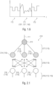
- Fig. 1.3 An example is provided in Fig. 1.3 .
- two different EPs 216' and 216" try to simultaneously communicate with the DM by sending wireless transmissions 113' and 113" to a REP 214.
- Both transmissions 113' and 113" are comb-like pilot sequences respectively indicated as 131' and 131" with a discrete number of subcarriers, which are numbered as S 1 ...S 8 (here, eight subcarriers are shown, but other numbers may be used).
- the first comb-like pilot sequence 131' only comprises the subcarriers S 1 and S 5
- the second comb-like pilot sequence 131" only comprises the subcarriers S 3 and S 7 .
- the subcarriers of the second sequence 131" are shifted of two positions with respect to the subcarriers S 1 and S 5 of the first sequence 131'. (Other shifts may be provided: for example, in case of shifting of three positions, the second sequence 131" would present the subcarriers S 4 and S 8 .)
- the non-occupied subcarriers are void (e.g., 0 magnitude of the bin).
- composition of the sequences 131' and 131" is received as sequence 131′′′ by the REP 214. Therefore, the two pilot sequences 131' and 131" do not collide. From the shift positions between the sequences, it is possible for the REP and/or the DM to obtain information from both EPs 216' and 216".
- the REP 214 may measure metrics regarding the link 218 and/or metrics relating to the quality, such as channel quality information (CQI), channel state information (CSI), and so on.
- CQI channel quality information
- CSI channel state information
- the obtained metrics may be signalled to the DM 212.
- one EP may receive comb-like pilot sequences from different REPs, so as to measure metrics associated to the link and/or the quality of the communication, and, subsequently, to signal them to the DM 212 via the REPs 214. This may occur, for example, when a "beacon frame" (see below) is transmitted from the DM to the EPs through the REPs. Accordingly, the EPs may measure metrics associated to the channel in one single measurement session.
- aspects for the generation of useful wireless signals e.g., for individual generating reference signals and/or for other purposes
- comb-like signals e.g., comb-like pilot sequences
- Optical signals e.g., visual optical signals
- the aspects relate to the topology and/or devices discussed above and/or to other, different topologies and/or devices.
- Time slots may substitute the subcarriers in the examples above.
- Fig. 1.4 shows an example relating to a communication device 140.
- the communication device 140 one of the devices 110, 120, 214, 216.
- the communication device 140 comprises a signal generator 141, which is implemented in hardware and/or in programming so as to generate an output signal 142, which may be a digital or analog signal and may be described in the time domain, TD, or in frequency domain, FD.
- the output signal 142 is provided to an emitter (e.g., the emitter 112) and provided (e.g., as wireless signal 113) to a receiver (which may in turn be one of the 110, 120, 214, 216).
- the signal generator 141 is input with at least the following information:
- the signals 142 may be orthogonal signals.
- the signals 142 are used for uniquely identifying the communication devices, transmitters (e.g., LED emitters) and/or the streams.
- the signal 142 may be a comb-like signal (e.g., to be used as the comb-like pilot sequence 131' or 1.31") and presents subcarriers (e.g., S 1 and S 5 for the device 216'; and S 3 and S 7 for the device 216") which are distant from each other for a particular number of positions (e.g., four positions).
- the distance between subcarriers may be fixed for each comb-like signal and may be the same for all the comb-like signal in the same network.
- Fig. 1.4a shows a more detailed example of a signal generator 141a, which mainly operates in the FD.
- the generator 141a is input with the information 143, 144, 145.
- the generator 141a comprises a subcarrier position definer 146, which defines the relative positions between subcarriers of the signal 141.
- the subcarrier position definer 146 takes into account:
- Another parameter that is kept into account is the number of transmitting communication devices (and/or transmitters and/or streams).
- a comb factor ⁇ may be defined, which keeps into account the number of other communication devices, transmitters and/or streams taking part to the network. Therefore, the comb factor ⁇ represents an example of information 144 associated to the number of transmitting communication devices, transmitters and/or streams in the network. In examples, up to ⁇ -1 communication devices may participate. Additional or alternative examples of information 144 may be used.
- the relative positions between the subcarriers of the same device (or transmitter or stream) are defined at the subcarrier position definer 146.
- void positions are not occupied by any subcarrier, as they may be occupied by subcarrier of other devices, transmitters or streams.
- the output of the subcarrier position definer 146 may be a sequence Z in the spectral domain.
- the subcarrier position definer 146 may be input by a pseudo-noise sequence A L (which may be, for example, a Gold sequence, see Annex), also indicated with 149.
- a L which may be, for example, a Gold sequence, see Annex
- the pseudo-noise sequence A L may be up-sampled by the comb factor ⁇ (the added positions have magnitudes 0), to obtain the output sequence Z.
- the output sequence Z may therefore be provided to a subcarrier shifter 147, which shifts the subcarriers in the sequence Z.
- the sequence Z is shifted (e.g., rotated towards the right direction or left direction) by a number of positions S which is derived from the information 145 and regards the identification number of the communication device, transmitter or stream.
- An IFFT block (or another bloc for converting an FD signal into a TD signal) may be implemented to obtain the final signal 142 to be transmitted by a LED emitter as signal 113.
- Fig. 1.5 shows a method according to an example, performed, for example, by the generator 141 or 141a for constructing a reference sequence and/or a comb-like signal.
- step 151 information regarding OCR, A L , ⁇ , S is obtained (e.g., information 143, 144, 145, 149).
- a constant bias 0.5 is subtracted from A L (other values may be chosen).
- a L is up-sampled by comb factor ⁇ .
- a cyclic shift by S samples applies to sequence Y yielding sequence Z.
- the value of S identifies the specific stream or transmitter and is defined by the MAC via the PHY SAP.
- the sequence F is passed through an inverse fast Fourier transform (IFFT) which always yields a real-valued RS being specific for a given stream or transmitter.
- IFFT inverse fast Fourier transform
- different devices and/or transmitters may transmit frequency domain (FD) reference signals and/or comb-like sequences may be generated, which may be orthogonal with respect to each other.
- FD frequency domain
- a reference signal in the time domain which may be orthogonal with respect to each other.
- the reference signal is in generated in TD or FD, it is possible to generate it and transmit as a part of an optional field in a physical header (see Fig. 3.1 , numerals 312 and 318, as well as the description below).
- the reference signal is a specific analog waveform, which is associated to a communication device or a transmitter or a data stream. Notably, the other data may be transmitted using different modulation schemes, for example. Different transmitters or different communication devices are in general associated to different analog waveforms, reference signals, and/or comb-like sequences, and are therefore uniquely identified. In examples, a specific waveform is chosen from a plurality of waveforms.
- Fig. 1.6 shows an example in which reference signal 171 (which may be an example of signal 131', 131", and/or may be the signal 142 generated by the generator 141 and/or 141a) is generated between signals 172 and 173 (the signal evolution as in Fig. 1.6 may change according to different strategies and techniques). While signals 172 and 173 are generated using a particular modulation scheme (e.g., the modulation scheme used for transmitting all the other data, e.g., using elements of the structures 320 or 330, discussed below and in particular in sections 3.1.2.3 and 3.1.2.4, respectively), the waveform 171 may be obtained using the generator 141 or 14a and/or the method 150 (or other techniques discussed above and below). For example, the communication device may select between:
- the waveform 171 may be orthogonal, in TD or FD, to other waveforms that are simultaneously transmitted by other communication devise or transmitters.
- communication device for communicating with a plurality of other communication devices [optical communication devices] using a wireless link [wireless optical link], wherein the communication device is configured to use different codes [e.g.
- different codes of fixed or variable length] for communication with different of the other communication devices for example, to allow the other communication devices to identify which data is directed to them, for example, to achieve a code division multiple access
- the communication device is configured to vary a number of the codes and/or a length of the codes [for example, in dependence on a number of receiving other communication devices, and/or in dependence on a channel condition and/or in dependence on a desired data rate] and wherein the communication device is configured to vary a type of a pulse-amplitude modulation [e.g. a number of amplitude states of a pulse amplitude modulation] [e.g. to switch between 2-PAM,4-PAM.8-PAM and 16 PAM] [for example, in dependence on a number of receiving other communication devices, and/or in dependence on a channel condition and/or in dependence on a desired data rate].
- a pulse-amplitude modulation e.g. a number of amplitude states of a pulse amplitude modulation
- 16 PAM
- a communication device for communicating with a plurality of other communication devices [ optical communication devices] using a wireless link [wireless optical link],wherein the communication device is configured to use a Hadamard-coded modulation [for example, for communication with different of the other communication devices [via the wireless optical link; to allow the other communication devices to identify which data is directed to them; for example, to achieve a code division multiple access], wherein the communication device is configured to vary a number of used codes in the Hadamard coded modulation and a parameter M determining a number of amplitude states of a Pulse-Amplitude-Modulation (PAM) [, in dependence on a number of receiving other communication devices, and/or in dependence on a channel condition and/or in dependence on a desired data rate].
- PAM Pulse-Amplitude-Modulation
- a communication device for communicating with a plurality of other communication devices [e.g. optical communication devices] using a wireless link [e.g. a wireless optical link], wherein the communication device is configured obtain an extended header data unit, in which a header information [for example, a physical layer header, which describes a frame type and a length of a physical layer service data unit] is duplicated [e.g. repeated or copied multiple times], and to input the extended header data unit into a Reed-Solomon-Code-based forward error correction [e.g. error correction], to obtain an error-tolerant data unit [for example, an error-tolerant data unit representing the header information].
- a header information for example, a physical layer header, which describes a frame type and a length of a physical layer service data unit
- a Reed-Solomon-Code-based forward error correction e.g. error correction
- a communication device [optical communication device] for communicating with a plurality of other communication devices [optical communication devices] using a wireless link [wireless optical link], comprising:
- a communication device for communicating with a plurality of other communication devices [optical communication devices] using a wireless link [wireless optical link], wherein the communication device is configured to transmit a channel estimation frame [e.g. a "probe frame”] using a complete set [or full set] of optical transmitters [light emitting diodes or lasers], and wherein the communication device is configured to selectively transmit a data frame [e.g. a frame comprising data and/or configuration information] using selected [optical] transmitters [which may be a true subset or a subset in a proper sense of the complete set].
- a channel estimation frame e.g. a "probe frame”
- the communication device is configured to selectively transmit a data frame [e.g. a frame comprising data and/or configuration information] using selected [optical] transmitters [which may be a true subset or a subset in a proper sense of the complete set].
- a communication device for communicating with a plurality of other communication devices [optical communication devices] using a wireless link [wireless optical link], wherein the communication device is configured to transmit a plurality of data streams using a plurality of transmitters [optical transmitters], wherein the communication device is configured to determine, using which of the transmitters and using which intensities a first of the data streams is to be transmitted; and wherein the communication device is configured to determine, using which of the transmitters and using which intensities a second of the data streams is to be transmitted,
- the examples above and below may refer, instead to a communication device, to a set of multiple communication devices, The set may communicate with a plurality of other communication devices.
- This section proposes, inter alia, generic MAC procedures for coordinated operation of a VLC network operating in multipoint-to-multipoint mode and discusses the requirements for essential fields.
- the objective of this contribution is to enable coordinated operation for MP2MP (multi-point to multi-point) communication using visible light communication (VLC) in industrial wireless scenarios having high QoS requirements. High link availability and low latency are therefore required.
- the proposal is a centrally coordinated medium access (MAC) protocol for the entire VLC network consisting of multiple lights and multiple mobile devices.
- VLC has been a hot research topic in recent years.
- Most publications consider the application of VLC in indoor scenarios as a replacement or complement to Wi-Fi, coined as Li-Fi, where every light bulb is used as a wireless access point.
- industry is still sceptical about this idea as it is challenging and needs large volumes, low cost, low energy and miniaturized communication frontends that can be integrated in every light bulb and into mobile devices.
- these challenges can only be met on the long term, recent research was looking onto new use cases that can be realized more in the near term, in which the high requirements of Li-Fi can be relaxed and where the light can leverage its unique selling points in the ever-lasting competition with radio.
- a first such new use case is wireless backhauling of small radio cells. Those small radio cells will be most likely installed on each outdoor luminaire. Accordingly, VLC backhauling is related to the field of connected lighting.
- enterprise scenarios with e.g. secure wireless conference rooms in a bank, could be realized by using the light as a wireless medium, instead of radio, because it can be well localized and does not penetrate through walls.
- the first functionality it is performed by the so-called link adaptation and it is already part of the wireless MAC.
- the second functionality is performed by using the handover procedure from one cell to the other, and interference in managed in addition in a so-called mobility management entity (MME).
- MME mobility management entity
- the handover and interference management functionalities are now considered part of the MAC.
- the advantage is that decisions are made nearer to the wireless channel and systems can track mobility with significantly reduced delay and in a more reliable fashion than in 4G. This is in fact required for some of the new use cases such as industrial wireless communications considered for VLC.
- Higher reliability can be supported in general by coordinated multipoint transmissions, the simplest form of which is macro-diversity, Lower latency can be reached by making decisions related to mobility inside the RAN, and not involve a core network which introduces additional delays.
- a VLC domain (e.g., network 210) comprises a domain master (DM) 212, its associated relaying end points (REPs) 214 and end points (EPs) 216, see Fig. 2.1 .
- DM domain master
- REPs relaying end points
- EPs end points
- VLC domains Normally there is no visibility among different VLC domains, as they will be separated e.g. by walls. Otherwise, orthogonal operation of different domains is left as an implementer's issue, and can be realized e.g. by using different LED wavelengths, separate time slots or other frequency bands.
- Other VLC topologies P2P, P2MP, non-coordinated MP2MP shall also be considered orthogonal and not interfere with the coordinated topology in which strict QoS requirements are targeted.
- REPs 214 may be placed in a fixed location e.g. as part of the illumination infrastructure.
- REPs relay frames coming from the domain master (DM) to the EP.
- DM domain master
- the uplink frames originating from the EPs are relayed by the REPs and forwarded into the infrastructure network, ending in the DM.
- the DM 212 is not necessarily a dedicated physical device. Its functionality may be served by a virtual entity, co-located with a REP or placed in the cloud.
- the DM has both data and control plane capabilities in order to support the mobility of EPs in the VLC network.
- the DM 212 may provide a smart packet forwarding capability through the infrastructure network. It is able to steer the uplink and downlink traffic of mobile EPs through flexibly assigned REPs and the infrastructure network. Moreover, the DM 212 may take over essential MAC layer functions such as security, retransmissions and selection of transmission points.
- the DM 212 assigns wireless resources so that they are used orthogonal between adjacent EPs 216 and will be extensively reused between more distant ones.
- Wireless resources can be time slots and one REP or clusters of multiple REPs used for joint transmission and detection.
- CBTXOPs contention-based transmission opportunities
- Contention-free medium access is considered as the main operation mode. In the coordinated network topology, it is based on contention-free scheduling of VLC transmissions between the DM and EPs via the REPs. All nodes must therefore be synchronized and access the channel in an orthogonal manner. (although synchronization between REPs can be achieved using the IEEE 1588v2 precision time protocol (PTP) from a PTP grand master in the network infrastructure, the mobile End Points must support PTP also over the wireless VLC link.)
- PTP precision time protocol
- the DM creates and maintains a global medium access plan (MAP) which is valid for the entire coordinated VLC topology, using a scheduling algorithm.
- MAP medium access plan
- CFTXOPs contention-free transmission opportunities
- the aim of a mobile scheduling algorithm is to reuse space, to minimize inter-channel-interference (ICI) and to maximize the signal-to-interference-and-noise ratio (SINR).
- ICI inter-channel-interference
- SINR signal-to-interference-and-noise ratio
- Link quality can be summarized in a connectivity matrix (CM).
- CM connectivity matrix
- An example reduced CM is depicted in figure 2.2 (showing an example of a reduced connectivity matrix 221, CM, in downlink (left) and 222 uplink (right) direction). It contains only the binary values X or 0, indicating the presence or absence of a potential physical connection (i.e. a channel).
- the connectivity matrix can be extended by quantitative channel quality information (CQI), yielding e.g. a matrix with achievable rates, or even more detailed channel state information (CSI) which is in principle a complex number measuring the complex channel amplitude in the frequency domain what is useful for joint physical layer processing of the signals transmitted or received by multiple REPs.
- CQI quantitative channel quality information
- CSI channel state information
- the CM can be reduced, when not every pair of two nodes is considered to have a potential link. This may be the case when up- and downlink are orthogonally multiplexed, i.e. transmissions by EPs cannot be received by other EPs and transmissions by REPs not by other REPs vice versa. This is achieved e.g. by applying wavelength-division multiplexing (WDM) for up- and downlink.
- WDM wavelength-division multiplexing
- the reduced CM can then be split in two simple matrices for up and downlink each. An example for a reduced CM is depicted in figure 2.2 .
- CM 230 depicted for example in figure 2.3 represents that there are much more links in this scenario.
- Orthogonal and interference-free scheduling of transmissions under these circumstances is well known to introduce a huge increase of complexity in cellular networks operating in time-division duplex (TDD) mode, in particular if the split between up- and downlink is fully flexible among the cells.
- TDD time-division duplex
- a common, yet suboptimal practice is to tightly synchronize all network nodes and to introduce a flexible uplink/downlink split on a network-wide basis.
- the DM may have instantaneous knowledge of the CM. Accordingly, admitted EPs have to update their entries in the CM regularly. EPs joining the network have to measure their most visible REPs and inform the DM about them to be included in an updated CM. The period of these reports may vary depending on mobility and traffic needs of individual EPs.
- the DM may ensure that all REPs in a coordinated VLC network (e.g., 210) broadcast a beacon frame.
- the purpose of the beacon frame is to provide advertisement of the network and regular synchronization of the EPs with the network.
- the beacon frame contains, among other information, a resource specification, e.g. a time slot, for a single or multiple CBTXOPs in the MAC cycle designated for the network joining procedure.
- the CBTXOP for joining the network is global, i.e. uses the same resources in the entire network. In this way, deterministic transmission is possible at any point in the network so that there will be no interference for data transmissions having strict QoS requirements.
- a new EP can use a designated CTXOP to access the network.
- Newly arriving EPs may transmit packets after i) receiving a beacon which includes the designated CBTXOP and ii) gathering multi-cell channel information to multiple surrounding REPs and iii) providing feedback about their connectivity.
- CSMA/CA carrier-sense multiple access scheme with collision avoidance
- RTS/CTS ready-to-send/clear-to-send
- VLC links may suffer from rapidly deteriorating connectivity, e.g. if the line-of-sight (LOS) between a REP and an EP is suddenly broken. But the same EP can have free LOS links to multiple adjacent REPs simultaneously. Macro diversity is a simple scheme exploiting this opportunity, i.e. use adjacent REPs to jointly transmit or receive the same signal to one RP or from one EP, respectively.
- LOS line-of-sight
- All packets designated for a particular EP in the downlink are jointly transmitted via a cluster of REPs to which the EP is usually connected to, e.g. by using the above-mentioned macro-diversity scheme.
- received packets from the particular EP are forwarded to the DM, even if multiple copies are received by multiple REPs in the cluster and forwarded to the DM.
- the DM such redundant information can be used for joint detection.
- efficient distribution of packets can be reached in different ways, e.g. by assigning another VLAN identifier to each REP or cluster of REPs to which the EP can be connected.
- Downlink information is then sent as a broadcast packet from the DM to all REPs to which the EP is connected by using the corresponding downlink VLAN address.
- the EP can just transmit its packets to the MAC address of the DM, together with its own MAC address.
- the DM performs combining eventually, based on the common MAC address.) Either one copy with valid parity check is selected or all copies are combined such that the reliability of wireless transmissions is improved.
- each REP in a cluster the same data have to be transmitted.
- SynE synchronous Ethernet
- PTP precision time protocol
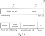
- Every frame 240 may be subdivided into two sections, as depicted in Figure 2.4 .
- the physical layer part 241 may permit to obtain synchronization and channel information at the receiver. Furthermore, it provides elementary control information for the data link layer, such as assigned resources as well as modulation and coding schemes used for data transmission.
- the second part 242 is payload.
- Transmissions within a VLC network can be classified by means of how many REPs transmit jointly:
- Local frames are transmitted by individual REPs or EPs in an interference-limited manner.
- OFDM orthogonal in space and time
- this can be implemented so that that a REP or EP is assigned another subcarrier comb, where the comb spacing is equal or larger than the frequency reuse factor F.
- the comb can be reused by a distant REP or EP, and thus the transmission is interference-limited. All parts of the local frame are transmitted by using the same subcarrier comb, i.e. preamble, channel estimation, header and eventually also local data.
- a VLC network and/or a domain master may be configured to distinguish different types of frames to be transmitted in downlink, the types comprising
- the generic beacon frame is an example for a frame of the first type and consists of a global frame transmitted simultaneously by all REPs in the VLC network. It contains a synchronization sequence, a channel estimation sequence and a header with information relevant for all EPs in the VLC domain.
- the common header contains a user-defined domain name, the MAC address of the DM, a feedback mode field, a global medium access plan (MAP) which indicates at least one or more MAC cycles, where CBTXOPs are scheduled.
- MAP global medium access plan
- EPs can use one of these CBTXOPs to access the network by using CSMA/CA with RTS/CTS. That is, a frame of the first type may, for instance, indicate a global medium access plan (MAP) which indicates at least one or more MAC cycles.
- MAP global medium access plan
- a frame of the third type may, for instance, contain a REP-specific training signal which enable an EP to estimate the channel to the REP in the downlink direction.
- a REP of a VLC network may be configured to intermittently transmit network training frames each carrying an REP-specific training signal in form of a pilot sequence, wherein header of the network training frames contains a reuse index indicating an index of reuse of the pilot sequence.
- the EP may be configured to identify a concrete REP based on such transmit network training frame, namely based on reuse index and pilot sequence.
- the pilot sequence may be characterized by a sequence index which may optionally also be contained in the header. In so far all the details described elsewhere herein may or may not nb combined with the just-mentioned and highlighted one.
- the generic feedback frame can be either global or regional and, thus, may be an example for a frame of the first or second type. As a global frame, it is commonly used for joining the network. Therefore, it must contain the connectivity information for the corresponding EP. It can happen that either the REP is the same for several EPs or subsets of REPs in the selected clusters are the same. The DM will then decide what set of REPs and what scheduling is used for a given EP. Such complex decisions may need more detailed feedback information. (In the downlink, the DM will need to request CQI feedback from EPs with overlapping REPs or clusters of REPs.
- the feedback mode (CM, CQI, CSI) is signaled by the DM in the header of a control frame. If the same feedback mode is used globally, this information is contained in the beacon signal. This global assignment can be overwritten by transmitting a regional control frame. In this way, the DM can switch between more or less advanced transmission schemes applied either in the entire VLC domain or for one REP or multiple adjacent REPs in a cluster. Usually, feedback is provided in a compressed manner to save overhead.
- the generic feedback frame may also contain additional information to authenticate the EP in the VLC domain.
- a VLC network and/or a domain master may be configured to activate different channel feedback modes in different portions of the VLC network.
- a default feedback mode may be set globally.
- Frames of lower scope such as frames of the second or first type may signal a deviation from the default mode so as to appoint another feedback mode.
- An EP of a VLC network may be configured to change its channel feedback mode according to frames of lower scope sent by the VLC network.
- the pilot sequence may be a comb-like pilot arrangement as explained below. In so far all the details described elsewhere herein may or may not nb combined with the just-mentioned and highlighted one.
- the generic medium access frame may be an example for a second type frame and informs the EP what transmissions are scheduled by transmitting the relayed medium access plan (RMAP).
- RMAP relayed medium access plan
- the medium access frame is regional and sent jointly by one REP or a cluster of adjacent REPs. Note that spatial reuse is typical for both, data and RMAP information. If EPs are distant from each other, interference between REPs or clusters of multiple REPs is negligible. Then the DM will select disjoint REPs, or disjoint clusters of REPs, for each EP.
- the beacon is a global frame transmitted jointly by all REPs in the VLC network.
- the CBTXOP allocation, contained in a beacon frame, is specified as part of the global MAP and must be extracted for all REPs. As a result, the information contained in the global MAP is split into two signals on the wireless hop: the beacon frame and the RMAP (see section 2.5b)).
- Multi-cell channel estimation may be performed in a dedicated time slot, allocated by the DM.
- the channel between all participating REPs and EPs must be measured on a regular basis. Therefore, at least one orthogonal measurement from every REP to every potential EP must be performed, and one from every EP to every potential REP.
- each transmitter sends pilot signals only on a grid of equally-spaced subcarriers. This whole comb is shifted by an integer number of subcarriers when using another REP, This way, pilots of adjacent REPs can be made orthogonal in the frequency domain. Likewise, distant REPs reuse the same comb.
- pilots arrive simultaneously on all subcarriers. By knowing the comb spacing and the REP-specific shifts, the receiver can extract the corresponding pilots and interpolate the channel between the available pilots (e.g. [1]).
- Multiplexing pilots can be done statically in the downlink. It is also possible to use the same scheme for local data transmissions of individual REPs, e.g. to communicate their REP identifier (ID), their MAC address and other local information. In the uplink direction, however, the EP's mobility forbids a static pilot assignment. For uplink channel estimation, pilots must be assigned dynamically.
- Figure 2.7 shows examples of pilot combs used for OFDM-based multi-cell channel estimation
- an EP's connectivity to the VLC network can vary over time.
- the EP may send an updated global feedback frame during the next available CBTXOP.
- Modified uplink connectivity may not be detected in this way as long as the EP remains idle. Hence, before an EP can start any uplink transmission, it has to send an updated feedback frame, even if downlink connectivity was unchanged.
- the uplink channel may be measured as part of the same frame transmitted for feedback delivery from the EP to the REP, or a cluster of REPs.
- an EP of a VLC network may be configured to enter, from idle mode, an active mode by transmitting a frame comprising a channel feedback signal to the VLC network, the frame also comprising pilot signals for enabling uplink channel estimation. In so far all the details described elsewhere herein may or may not nb combined with the just-mentioned and highlighted one.
- Feedback delivery happens in a designated time slot after receiving both, the beacon and the multi-cell channel estimation frame.
- the feedback packet is fed forward by the receiving REP, or the cluster of REPs, to the DM.
- Figure 2.8 shows a multicell channel estimation and feedback delivery.
- the DM maintains a global MAP, which has to be disseminated periodically to all REPs.
- the overhead to send the whole MAP is high and not all information is required at all EPs.
- the particular part of the MAP is sent to the EP which is needed for demodulation of its own data.
- the relayed MAP RMAP
- the DM assigns spatial and temporal resources so that interference is limited.
- data are always modulated in a conservative, interference-aware manner so that detection is always possible.
- the same can be assumed for control traffic such as the RMAP transmission.
- the RMAP can be transmitted in parallel in different clusters of REPs, as illustrated in Figure 2.9 (showing a MAP distribution in different clusters of REPs).
- the G.hn MAC is already centrally coordinated.
- the DM generates a MAP for every MAC cycle and broadcasts it to all nodes in its domain.
- the MAP frame includes defines start time and length of TXOPs and the nodes that may use the TXOP for transmission (G.9960, 8.2.1, 8.3.1).
- the frame specification used for MAP transmission may also be used for G.vlc (G.9961, 8.8).
- MAPs must be transmitted over the infrastructure network.
- REPs would have to apply MAPs received over an Ethernet interface.
- the relaying of MAPs is already part of the G.hn specification (G.9961, 8.8.1, 8.5.6).
- G.9961, 8.8.1, 8.5.6 the G.hn specification
- not all nodes are connected to each other, not the whole MAP but only a regional fraction of the MAP has to be broadcast by a cluster of REPs over the VLC channel.
- G.hn synchronization of the nodes is achieved based on the MAP frame transmission.
- a node, decoding the MAP frame reads the NTR field, containing the DM's time stamp, and synchronizes its clock accordingly. (G.9960, 7.1.6.2).
- this synchronization of time must be supported by the PTP protocol.
- the frequency between all REPs must be synchronized via the infrastructure network, e.g. by using SyncE.
- G.hn specifies a minimum MAC cycle duration of 5ms (G.9961, Table 8-14).
- Shorter MAC cycles may be beneficial for higher mobility in VLC networks. This could be introduced in conjunction with increased subcarrier spacing and reduced symbol duration, accordingly.
- G.hn defines shared TXOPs for CSMA-based multiple access.
- the time slot used for joining the domain in the proposed VLC system could be realized by scheduling a CBTXOP in the MAP.
- the network admission protocol (G.9961, 8.6.1.1) can be reused, eventually the relayed network admission procedure may be used over a REP (G.9961, 8.6.1.2).
- G.hn specifies the establishment of traffic flows, with a guaranteed bandwidth (G.9961, 8.6.2).
- G.9961, 8.6.2 a bandwidth that guarantees the link availability and its capacity. Therefore, reserving of flows is not applicable or duration must be limited according to the expected availabilities.
- G.hn specifies the collection of topology information at the DM, in case of centralized routing and topology management (CRTM) mode (G.9961, 8.6.4). Therefore, the DM has the possibility to control the links that are used for data transmission.
- CRTM centralized routing and topology management
- the DM must be capable of transmitting and receiving a series of management frames. As most functionality in the current G.hn standard can also be achieved over a relay via an EP, it should be possible to achieve the same functionality by relaying over an infrastructure network. Specifically this includes the following functionality (G.9961, 8.6):
- Beacon frame transmission is intended as a global transmission. It serves the purposes of synchronization of all EPs with the network, advertisement of network presence and assignment of CBTXOPs for network admission.
- the beacon frame is closely related to the MAP frame defined in G.hn.
- the beacon may be transmitted using a very robust modulation and coding schemes similar to transmitting a (R)MAP-D in G.hn (G.9960, 7.1.2.3.2.1.10).
- the beacon frame does not contain any complete MAP, but merely the specification of CBTXOPs for network admission. Communication of the remaining MAP information is part of the medium-access-frame (RMAP) and transmitted regionally.
- the beacon header must be transmitted bitwise equal by any REP in the network. Additional information, destined for the whole network, may be extracted from the global MAP and transmitted via the beacon frame in the payload section.
- the multi-cell channel estimation frame is transmitted locally and it enables downlink channel estimation.
- Local transmissions use orthogonal multiplexing of transmissions from adjacent REPs.
- G.hn there is a dedicated probe frame for the purpose of channel estimation.
- the comb approach described above can be realized by masking specific subcarriers in G.hn for specific REPs for the duration of the whole probe frame.
- multiple REPs could jointly transmit probe frames, whose payload (i.e. probe symbols a.k.a. pilot symbols) are orthogonal in the frequency.
- the missing channel information can be interpolated in software, if received pilots are made accessible by the PHY layer.
- location information of each REP may be transmitted as meta-information with those local probe frames, based on which an EP could precisely calculate its position using trilateration. This is simpler than calculating the location in the DM by gathering information from EPs over a dedicated protocol.
- the feedback frame is transmitted by EPs in uplink direction.
- This can be realized using a general-purpose data frame, containing a management message (LCDU, similar to other channel estimation messages).
- the new management frame could also incorporate all additional information required by the channel estimation protocol. Using an uncontended CBTXOP time slot for feedback transmission by every EP is recommended.
- Albeit uplink channel estimation could be achieved separately using a probe frame similar to the downlink channel estimation, it would be efficient to perform the uplink channel estimation procedure simultaneously within the feedback transmission frame.
- RMAPs The allocation of TXOPs, except of the global network admission CBTXOP, is transmitted via RMAPs. They are related to RMAPs from G.hn in terms of being relayed by the REPs. However, for VLC, RMAPs transmitted by the REPs may not contain the complete network MAP. Rather they contain only allocations concerning the EPs that physically receive the RMAP. Therefore, RMAPs are transmitted regionally.
- the frame format can be adopted from G.hn's RMAP frames. Nevertheless, the transmission of RMAPs may not always happen in the same timeslot for all clusters. Between overlapping clusters, it may be made orthogonal by using different time slots so that interference is avoided.
- the MAC layer For joint transmission of data it is required that the MAC layer has the same data available on all REPs of a cluster. The same data are multicast by the DM to all REPs in the cluster in the infrastructure network. Clusters would therefore be static, or at least preconfigured e.g. by using dedicated VLAN IDs for each cluster and dynamically selecting it in an appropriate control message protocol.
- the source DID within the PHY-frame must be the same.
- a virtual and temporary DID could be assigned to a cluster.
- the establishment of clusters could be separated from the data path, and constitute a separated management process.
- the HARQ and acknowledgement mechanism interferes with the macro-diversity approach.
- macro diversity it is intuitive, that either no ACK should be requested, or that the non-receipt of an ACK at a REP should not trigger a retransmission. Rather the non-receipt of an ACK should be signaled further to the DM, which would take over responsibility of the retransmission from a centralized buffer.
- the Pulsed Modulation (PM) PHY enables moderate data rates from 1 Mbit/s to some 100 Mbit/s.
- the main approach is to achieve high data rates by using a high optical clock rate (OCR) while keeping spectral efficiency low.
- OCR optical clock rate
- This approach offers enhanced reach in applications where power efficiency is an issue, e.g. for uplink and Internet of Things (IoT).
- 2-Pulse-Amplitude Modulation (PAM) with 8B10B line coding and variable optical clock rate or M-ary PAM with Hadamard-Coded Modulation (HCM) are used, together with Reed-Solomon (RS) forward error correction (FEC).
- RS Reed-Solomon
- the PM PHY may include means to adapt the data rate and reliability of the link to varying channel conditions by i) varying the OCR, and/or ii) varying the modulation alphabet size M for PAM and the number of codes used in HCM and/or iii) selecting the most appropriate set of transmitters.
- the numerology of the PM PHY is defined in Table 1, where only case i) is considered.
- Table 1 Numerology for Pulsed Modulation PHY Opt. clock rate /MHz Opt. clock cycle/ ns T seq / ns T CP /n s N seq /optical clock cycles N CP /optical clock cycles MCS for payload Data rate/ Mbit/s Channel estimation sequence (Appendix 6.25 160 5120 160 32 1 4.7 A 32 12.5 80 64 2 9.4 A 64 25 40 128 4 2-PAM 19 A 128 50 20 256 8 8B10B 38 A 256 100 10 512 16 RS(256,248) 75 A 512 200 5 1024 32 150 A 1024
- the reference clock can also be obtained via Ethernet using the precision time protocol (PTP) defined in IEEE std. 1588v2. Jitter can be improved by combining PTP with synchronous Ethernet (SynchE) defined in ITU-T rec. G.8262.
- the PM PHY may use the PPDU format 310 shown in Figure 3.1 . It may comprise a synchronization header (SHR) 311, physical layer header (PHR) 312 and PHY payload (PSDU) 313.
- SHR synchronization header
- PHR physical layer header
- PSDU PHY payload
- the preamble 314 may enable both, cross- and autocorrelation with an appropriate window size [1-4].
- the base sequence A N a specific pseudo-noise sequence of length N may be used, see Annex 1).
- a N may be repeated six times (or another number of times greater than four in other examples) yielding a total sequence length of 6*N.
- Each base sequence may be multiplied with positive or negative sign as given below which is known to create a sharper peak after autocorrelation, compared to a double sequence of the same total length [4].
- the preamble may finally be passed through the 2-PAM Modulator.
- Channel estimation (CE) 315 may permit equalization and subsequent detection of header information and data.
- the CE sequence may allow frequency-domain equalization and hence comprise a base sequence and a cyclic prefix (CP). Measured in time units, the time durations of both, the base sequence T seq and the cyclic prefix T CP , may be maintained, independent of the OCR. By increasing OCR, the number of clock cycles for the sequence and for the CP, i.e. N seq and N CP , respectively, increase proportionally, see Table 1.
- the CE sequence may finally be passed through a 2-PAM modulator.
- the PHY header 316 may define the fields given in Table 3.
- the PSDU length scales from 0 up to aMaxPHYFrameSize.
- MCS defines the used modulation and coding schemes.
- MCS is a number for single-stream transmission.
- Field Octet Bits Values [0] reserved reserved [3:1] Modulation 0:2-PAM ... 3:16-PAM Stream 1 3 >3: reserved [7:4]
- Adaptive transmission allows the PM PHY to be operated in variable channel conditions by selecting an appropriate MCS according to the channel.
- CQI feedback is computed at the receiver and sent by the MAC layer in a control message over the reverse link to the transmitter side).
- RS_type defines the use of time- or frequency-domain reference signals (RS) in the optional field.
- N RS is the number of RS in the optional field.
- the sequence index for the specific RS to be used is assigned to each transmitter through the PHY SAP.
- Relaying mode specifies the mode of relaying operation (amplify-and-forward, decode-and forward).
- Relay duplex mode specifies the duplex mode for relaying (time- or full duplex).
- the header check sequence may use CRC-16 as defined in Annex C.
- the HCS bits may be be processed in the transmitted order.
- the registers may be be initialized to all ones.
- Optional fields 318 may contain reference symbols (e.g., 131', 131") for multiple-input multiple-output (MIMO) channel estimation, for example.
- MIMO RS For MIMO RS, repetitions, FEC, line coding and HCS do not apply.
- MIMO RS can be defined in time- and frequency domain. The use of time- or frequency-domain RS is configurable via the MAC SAP. At lower OCR, typically, time-domain RS are appropriate. At higher OCR, frequency-domain RS apply.
- Time-domain (TD) RSs are orthogonal in the time domain and constructed as follows.
- the value of i is used to identify the specific transmitter and defined by the MAC via the PHY SAP.
- H k H k ⁇ 1 H k ⁇ 1 H k ⁇ 1 ⁇ H k ⁇ 1 .
- the resulting sequence is scrambled symbol-wise by logical XOR operation with the base sequence A N after subtracting a constant value of 0.5 from A N .
- All sequences in H K are mutually orthogonal.
- the XOR operation with A N does not change the orthogonality of sequences but improves cross-correlation properties which is beneficial in case of multi-path [5, 6]. Note that the sequence for the first stream or transmitter just contains A N ).
- the communication device may:
- the following process may be performed by the signal generator 141 or 141a.
- Frequency-domain (FD) RSs allow orthogonal detection of multiple data streams or signals from multiple transmitters and are orthogonal in the frequency domain.
- a specific comb of subcarriers identifies a particular stream or transmitter.
- the value of ⁇ is defined by the MAC via the PHY SAP taking the fundamental relation ⁇ ⁇ N seq / (2*N CP ) into account yielding.
- values of L are used for a given OCR.
- Table 6 Base sequence length L for FD RS depending on the OCR and the comb factor ⁇ .
- N RS *( ⁇ -1) streams can be identified.
- Decompose the identifier of the i th stream or transmitter as i a*( ⁇ -1)+b where b ⁇ -1.
- the communication device may:
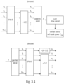
- the structure 320 in Fig. 3.2 applies to the transmission of the header. Scrambling 321 is optional to randomize uncoordinated interference. For improved error protection, the header can be repeated at 322 (duplicated). 8B10B line encoding 323 may apply to the header. Header encoding may use RS(36, 24) as defined below. According to [12, 13], a particular order of line and channel coding shown in Fig. 3.2 achieves lowest error rate. After FEC 324 (e.g., a Reed-Solomon FEC), only the systematic part of the binary output code word (24 bits) is well balanced.
- FEC 324 e.g., a Reed-Solomon FEC
- a spatial pre-coder 328 may select what element (e.g., communication devices and/or transmitters, such a as LED emitters) will sent out the header and how.
- Scrambling can be defined by the MAC layer through the PHY SAP. If used, scrambling is based on a pseudo-random binary sequence (PRBS) being characteristic for a given data stream.
- PRBS pseudo-random binary sequence
- the line encoder uses 8B10B code.
- 8B10B encoding see ANSI/INCITS 373 and Appendix 3).
- Bit-to-symbol mapping is based on 2-PAM. Each input bit is mapped onto one symbol as ⁇ 0, 1 ⁇ to ⁇ 0, 1 ⁇ , respectively. A constant value of 0.5 is then subtracted to make the output DC free. Setting the modulation amplitude and the bias of the LED is due to the optical frontend.
- the spatial precoder may be the same as for the payload, see section 3.1.2.4.7.
- the structure 330 in Fig. 3.3 may apply to transmission of the payload, which besides data frames may also contain control and management information defined by the MAC layer.
- Scrambling at 331 is optional to randomize uncoordinated interference.
- 8B10B line coding 332 may apply first.
- the payload uses RS(256, 248) code as defined below. According to [12, 13], a particular order of line and channel coding achieves lowest error rates.
- HCM Hadamard Coded Modulation
- 8B10B line coding is not used while M-PAM with M ⁇ 2 can be used.
- a spatial precoder 338 may select finally what set of transmitters will sent out the payload and how.
- Scrambling can be defined by the MAC layer through the PHY SAP. If used, scrambling is based on a pseudo-random binary sequence (PRBS) being characteristic for a given data stream.
- PRBS pseudo-random binary sequence
- RS(256, 248) encoder and decoder For constructing the RS(256, 248) encoder and decoder, a symbol width of 10 is used, due to the output of 8B10B line coding. Accordingly, the generator polynomial x 10 +x 3 +1 is used. Scaling factor is 1 and generator start equal to 0.
- the line encoder uses 8B10B.
- 8B10B encoding see ANSI/INCITS 373 and [3].
- line coding is set to 1B1B, i.e. deactivated.
- HCM Hadamard Coded Modulation
- HCM multiples a vector of N data symbols (where N is a power of two) with a Hadamard matrix, denoted as fast Walsh-Hadamard transform (FWHT).
- FWHT fast Walsh-Hadamard transform
- the complement of H is a binary matrix in which each element h of the matrix is replaced by 1-h.
- the spatial precoder is a matrix-vector operation P ⁇ x operating symbol-wise when using time-domain RS and subcarrier-wise when using frequency-domain RS.
- the transmitter multiplies the 1x1 scalar stream of header symbols x with the N ERS x1 vector P which contains all ones. All transmitters (and/or communication devices) broadcast the same header information (global transmission). The master coordinator in the infrastructure network sends the header information to all transmitters. All transmitters send in a synchronous manner. How to realize synchronization of multiple distributed OWC transmitters is out of scope for this standard.
- the transmitter multiplies the 1x1 stream of header information symbols x with the N ERS x1 precoding vector P which contains ones for all active transmitters in a coordinated transmission cluster and zeros elsewhere. All transmitters (and/or communication devices) in the cluster broadcast the same header information (regional transmission).
- the master coordinator in the infrastructure network sends header information to all active transmitters in a coordinated transmission cluster. All transmitters send in a synchronous manner. How to realize synchronization of multiple distributed OWC transmitters is out of scope for this standard.
- examples may be implemented as a computer program product with program instructions, the program instructions being operative for performing one of the methods when the computer program product runs on a computer.
- the program instructions may for example be stored on a machine readable medium.
- an example of method is, therefore, a computer program having a program instructions for performing one of the methods described herein, when the computer program runs on a computer.
- a further example of the methods is, therefore, a data carrier medium (or a digital storage medium, or a computer-readable medium) comprising, recorded thereon, the computer program for performing one of the methods described herein.
- the data carrier medium, the digital storage medium or the recorded medium are tangible and/or non-transitionary, rather than signals which are intangible and transitory.
- a further example of the method is, therefore, a data stream or a sequence of signals representing the computer program for performing one of the methods described herein.
- the data stream or the sequence of signals may for example be transferred via a data communication connection, for example via the Internet.
- a further example comprises a processing means, for example a computer, or a programmable logic device performing one of the methods described herein.
- a further example comprises a computer having installed thereon the computer program for performing one of the methods described herein.
- a further example comprises an apparatus or a system transferring (for example, electronically or optically) a computer program for performing one of the methods described herein to a receiver.
- the receiver may, for example, be a computer, a mobile device, a memory device or the like.
- the apparatus or system may, for example, comprise a file server for transferring the computer program to the receiver.
- a programmable logic device for example, a field programmable gate array
- a field programmable gate array may cooperate with a microprocessor in order to perform one of the methods described herein.
- the methods may be performed by any appropriate hardware apparatus.
Landscapes
- Engineering & Computer Science (AREA)
- Signal Processing (AREA)
- Computer Networks & Wireless Communication (AREA)
- Physics & Mathematics (AREA)
- Electromagnetism (AREA)
- Power Engineering (AREA)
- Optics & Photonics (AREA)
- Mobile Radio Communication Systems (AREA)
- Optical Communication System (AREA)
Applications Claiming Priority (5)
| Application Number | Priority Date | Filing Date | Title |
|---|---|---|---|
| EP17186340 | 2017-08-15 | ||
| EP18150523 | 2018-01-07 | ||
| EP18151869 | 2018-01-16 | ||
| EP18178372 | 2018-06-18 | ||
| PCT/EP2018/072076 WO2019034672A1 (en) | 2017-08-15 | 2018-08-14 | NETWORK AND WIRELESS DEVICES |
Publications (3)
| Publication Number | Publication Date |
|---|---|
| EP3669469A1 EP3669469A1 (en) | 2020-06-24 |
| EP3669469B1 true EP3669469B1 (en) | 2025-04-30 |
| EP3669469C0 EP3669469C0 (en) | 2025-04-30 |
Family
ID=63113561
Family Applications (1)
| Application Number | Title | Priority Date | Filing Date |
|---|---|---|---|
| EP18750471.7A Active EP3669469B1 (en) | 2017-08-15 | 2018-08-14 | Wireless network and devices |
Country Status (7)
| Country | Link |
|---|---|
| US (1) | US11212003B2 (https=) |
| EP (1) | EP3669469B1 (https=) |
| JP (1) | JP7341980B2 (https=) |
| KR (1) | KR102396938B1 (https=) |
| CN (1) | CN111213328B (https=) |
| ES (1) | ES3034523T3 (https=) |
| WO (1) | WO2019034672A1 (https=) |
Families Citing this family (13)
| Publication number | Priority date | Publication date | Assignee | Title |
|---|---|---|---|---|
| WO2020182849A1 (en) * | 2019-03-14 | 2020-09-17 | Abb Schweiz Ag | Method of authentication of wireless communication based on physical layer security |
| WO2020216468A1 (de) * | 2019-04-25 | 2020-10-29 | Sew-Eurodrive Gmbh & Co. Kg | Verfahren zur datenübertragung zwischen einem ersten und einem zweiten modul und anlage mit mobilteilen zur durchführung des verfahrens |
| DE102019210177B4 (de) * | 2019-07-10 | 2021-05-20 | Fraunhofer-Gesellschaft zur Förderung der angewandten Forschung e.V. | Verfahren zum Herstellen einer gegenläufig magnetisierten Magnetstruktur |
| KR20250057150A (ko) | 2019-10-02 | 2025-04-28 | 코닌클리케 필립스 엔.브이. | Harq 프로세스/엔티티 기반 업링크 다중화 |
| EP4042606A1 (en) * | 2019-10-10 | 2022-08-17 | Infinera Corporation | Optical subcarrier dual-path protection and restoration for optical communications networks |
| US11038661B1 (en) * | 2019-12-11 | 2021-06-15 | Wipro Limited | System and method for managing interference in Li-Fi communication networks |
| CN111541485B (zh) * | 2020-04-23 | 2021-04-06 | 清华大学 | 高相关性信道下的可见光mimo通信系统 |
| EP4226586B1 (en) * | 2020-10-05 | 2024-02-21 | Signify Holding B.V. | Efficient modulation control |
| CN114615748B (zh) * | 2020-12-08 | 2026-02-06 | 中国移动通信有限公司研究院 | 数据传输方法、装置、相关设备及存储介质 |
| EP4396950A1 (en) * | 2021-09-03 | 2024-07-10 | Fraunhofer-Gesellschaft zur Förderung der angewandten Forschung e.V. | Transmission of time and code multiplexed pilot sequences |
| CN116112118A (zh) * | 2021-11-10 | 2023-05-12 | 华为技术有限公司 | 数据传输方法和装置 |
| WO2024094473A1 (en) | 2022-10-31 | 2024-05-10 | Signify Holding B.V. | Code-based sector selection for wireless communication |
| US20250133618A1 (en) * | 2023-10-22 | 2025-04-24 | Big Field Global Pte. Ltd. | Method for channel state feedback in a non-simultaneous transmit and receive (nstr) operation mode |
Family Cites Families (21)
| Publication number | Priority date | Publication date | Assignee | Title |
|---|---|---|---|---|
| JP3340278B2 (ja) * | 1995-03-30 | 2002-11-05 | 株式会社東芝 | 符号多重通信装置 |
| JP4031355B2 (ja) | 2002-11-25 | 2008-01-09 | 日本放送協会 | Ofdm変調信号伝送方法及びその送信側装置と受信側装置 |
| US7706328B2 (en) | 2006-01-04 | 2010-04-27 | Qualcomm Incorporated | Methods and apparatus for position location in a wireless network |
| US7991090B2 (en) * | 2006-05-04 | 2011-08-02 | Broadcom Corporation | Method and system for reordered QRV-LST (layered space time) detection for efficient processing for multiple input multiple output (MIMO) communication systems |
| KR100891769B1 (ko) * | 2007-05-30 | 2009-04-07 | 삼성전자주식회사 | 무선 가시광 통신 시스템 |
| FR2928509B1 (fr) | 2008-03-04 | 2011-01-14 | Commissariat Energie Atomique | Procede de codage spatio-temporel differentiel. |
| KR101071455B1 (ko) * | 2008-12-16 | 2011-10-10 | 한국전자통신연구원 | 시퀀스 지연 및 고속동작이 가능한 골드 코드 생성 장치 |
| KR100921954B1 (ko) * | 2009-01-30 | 2009-10-23 | 주식회사 아이디로 | 가시광 다중 통신 시스템 |
| KR20100138260A (ko) | 2009-06-24 | 2010-12-31 | 주식회사 팬택 | 무선통신 시스템에서 전력 할당방법 및 그 장치, 이를 적용한 송수신장치 신호전송 |
| US8325685B2 (en) * | 2010-02-12 | 2012-12-04 | Research In Motion Limited | System and method for improved control channel transmit diversity |
| US9042281B2 (en) * | 2010-12-08 | 2015-05-26 | At&T Intellectual Property I, L.P. | Method and apparatus for initializing an RFID tag via an optical display |
| KR101926900B1 (ko) * | 2011-08-12 | 2018-12-07 | 인터디지탈 패튼 홀딩스, 인크 | 다중 입력 다중 출력 동작을 위한 방법 및 장치 |
| US9749012B2 (en) * | 2014-03-14 | 2017-08-29 | Semtech Corporation | Synchronized slotted power line communication |
| US9900199B2 (en) | 2014-05-06 | 2018-02-20 | Qualcomm Incorporated | Systems and methods for improvements to training field design for increased symbol durations |
| US9590730B2 (en) | 2014-10-01 | 2017-03-07 | Futurewei Technologies, Inc. | Optical transmitter with optical receiver-specific dispersion pre-compensation |
| US20160360141A1 (en) | 2015-06-03 | 2016-12-08 | Mitsubishi Electric Research Laboratories, Inc. | System and Method for Hybrid Wireless Video Transmission |
| JP6470151B2 (ja) * | 2015-09-07 | 2019-02-13 | 株式会社東芝 | 無線通信機、無線通信システム、無線通信方法およびプログラム |
| EP3375112B1 (en) | 2015-11-10 | 2019-12-18 | Fraunhofer Gesellschaft zur Förderung der angewandten Forschung E.V. | System and method for providing a wireless communication with a mobile device |
| US10181864B2 (en) * | 2016-02-26 | 2019-01-15 | Altera Corporation | Methods and apparatus for performing reed-solomon encoding |
| EP3348000A1 (en) * | 2016-09-13 | 2018-07-18 | Telefonaktiebolaget LM Ericsson (publ) | Mu-mimo communication in systems with antenna subarrays |
| US10187163B2 (en) * | 2017-03-06 | 2019-01-22 | Osram Sylvania Inc. | Self-locating light-based communication enabled luminaires |
-
2018
- 2018-08-14 WO PCT/EP2018/072076 patent/WO2019034672A1/en not_active Ceased
- 2018-08-14 ES ES18750471T patent/ES3034523T3/es active Active
- 2018-08-14 CN CN201880066394.7A patent/CN111213328B/zh active Active
- 2018-08-14 EP EP18750471.7A patent/EP3669469B1/en active Active
- 2018-08-14 KR KR1020207007319A patent/KR102396938B1/ko active Active
- 2018-08-14 JP JP2020509095A patent/JP7341980B2/ja active Active
-
2020
- 2020-02-14 US US16/791,127 patent/US11212003B2/en active Active
Also Published As
| Publication number | Publication date |
|---|---|
| US11212003B2 (en) | 2021-12-28 |
| KR102396938B1 (ko) | 2022-05-13 |
| KR20200038989A (ko) | 2020-04-14 |
| JP7341980B2 (ja) | 2023-09-11 |
| US20200195344A1 (en) | 2020-06-18 |
| EP3669469A1 (en) | 2020-06-24 |
| EP3669469C0 (en) | 2025-04-30 |
| CN111213328A (zh) | 2020-05-29 |
| WO2019034672A1 (en) | 2019-02-21 |
| CN111213328B (zh) | 2023-06-16 |
| JP2020532899A (ja) | 2020-11-12 |
| ES3034523T3 (en) | 2025-08-19 |
Similar Documents
| Publication | Publication Date | Title |
|---|---|---|
| EP3669469B1 (en) | Wireless network and devices | |
| US10326524B2 (en) | System and method for providing a wireless communication with a mobile device | |
| JP2020532899A5 (https=) | ||
| CN109906661B (zh) | 用于无线系统中的随机接入的方法和装置 | |
| JP7025423B2 (ja) | 無線通信システムにおいて、参照信号を送信する方法及びそのための装置 | |
| Ye et al. | Uplink nonorthogonal multiple access technologies toward 5G: A survey | |
| US8830926B2 (en) | Method for network co-ordination in a mobile communications system and apparatus thereof | |
| Au et al. | Uplink contention based SCMA for 5G radio access | |
| CN109560910B (zh) | 用于虚拟(基带)载波聚合宽带lte的设备、网络和方法 | |
| EP3915236A1 (en) | Orthogonal multiple access and non-orthogonal multiple access | |
| CN105474733B (zh) | 用于无线前传的传输和调度方案 | |
| KR20180096729A (ko) | 개선된 통신 시스템용 프레임 구조를 위한 방법 및 장치 | |
| KR20160039672A (ko) | 적응성 시스템 파라미터를 가진 확장 디지털 통신을 위한 시스템 및 방법 | |
| JP2011526102A (ja) | 送信シンボルの割り当てと推定をするための装置 | |
| US8743788B2 (en) | Method and device for sending and receiving a reference signal | |
| WO2023010369A1 (en) | Frequency hopping in noma | |
| JPWO2019034672A5 (https=) | ||
| Tong et al. | Enabling technologies for 5G air-interface with emphasis on spectral efficiency in the presence of very large number of links | |
| US12388496B2 (en) | Apparatus and method for allocating resources in time domain | |
| US8724567B2 (en) | Method and apparatus using frame structure for wireless mesh networks | |
| TWI465062B (zh) | Coordinated Multipoint Data Transmission Method Based on Orthogonal Overlay Codes | |
| US20240322969A1 (en) | Apparatus and methods for indicating dmrs ports for user equipment in a wireless communication system | |
| KR20250111166A (ko) | 정보 전송 방법 및 장치, 저장 매체, 전자 장치 | |
| BUDHIRAJA et al. | A Systematic Review on NOMA Variants for 5G Networks | |
| Prabakaran et al. | Performance analysis of uplink MIMO in 2× 2 mobile WiMAX system |
Legal Events
| Date | Code | Title | Description |
|---|---|---|---|
| STAA | Information on the status of an ep patent application or granted ep patent |
Free format text: STATUS: UNKNOWN |
|
| STAA | Information on the status of an ep patent application or granted ep patent |
Free format text: STATUS: THE INTERNATIONAL PUBLICATION HAS BEEN MADE |
|
| PUAI | Public reference made under article 153(3) epc to a published international application that has entered the european phase |
Free format text: ORIGINAL CODE: 0009012 |
|
| STAA | Information on the status of an ep patent application or granted ep patent |
Free format text: STATUS: REQUEST FOR EXAMINATION WAS MADE |
|
| 17P | Request for examination filed |
Effective date: 20200313 |
|
| AK | Designated contracting states |
Kind code of ref document: A1 Designated state(s): AL AT BE BG CH CY CZ DE DK EE ES FI FR GB GR HR HU IE IS IT LI LT LU LV MC MK MT NL NO PL PT RO RS SE SI SK SM TR |
|
| AX | Request for extension of the european patent |
Extension state: BA ME |
|
| DAV | Request for validation of the european patent (deleted) | ||
| DAX | Request for extension of the european patent (deleted) | ||
| STAA | Information on the status of an ep patent application or granted ep patent |
Free format text: STATUS: EXAMINATION IS IN PROGRESS |
|
| 17Q | First examination report despatched |
Effective date: 20220104 |
|
| RAP3 | Party data changed (applicant data changed or rights of an application transferred) |
Owner name: FRAUNHOFER-GESELLSCHAFT ZUR FOERDERUNG DER ANGEWANDTEN FORSCHUNG E.V. |
|
| REG | Reference to a national code |
Ref country code: DE Ref legal event code: R079 Ipc: H04L0005140000 Ref country code: DE Ref legal event code: R079 Ref document number: 602018081508 Country of ref document: DE Free format text: PREVIOUS MAIN CLASS: H04B0010110000 Ipc: H04L0005140000 |
|
| RIC1 | Information provided on ipc code assigned before grant |
Ipc: H04L 27/04 20060101ALI20241002BHEP Ipc: H04L 5/00 20060101ALI20241002BHEP Ipc: H04B 10/116 20130101ALI20241002BHEP Ipc: H04B 10/11 20130101ALI20241002BHEP Ipc: H04L 27/26 20060101ALI20241002BHEP Ipc: H04L 27/00 20060101ALI20241002BHEP Ipc: H04L 25/02 20060101ALI20241002BHEP Ipc: H04L 5/14 20060101AFI20241002BHEP |
|
| GRAP | Despatch of communication of intention to grant a patent |
Free format text: ORIGINAL CODE: EPIDOSNIGR1 |
|
| STAA | Information on the status of an ep patent application or granted ep patent |
Free format text: STATUS: GRANT OF PATENT IS INTENDED |
|
| INTG | Intention to grant announced |
Effective date: 20241125 |
|
| GRAS | Grant fee paid |
Free format text: ORIGINAL CODE: EPIDOSNIGR3 |
|
| GRAA | (expected) grant |
Free format text: ORIGINAL CODE: 0009210 |
|
| STAA | Information on the status of an ep patent application or granted ep patent |
Free format text: STATUS: THE PATENT HAS BEEN GRANTED |
|
| AK | Designated contracting states |
Kind code of ref document: B1 Designated state(s): AL AT BE BG CH CY CZ DE DK EE ES FI FR GB GR HR HU IE IS IT LI LT LU LV MC MK MT NL NO PL PT RO RS SE SI SK SM TR |
|
| REG | Reference to a national code |
Ref country code: CH Ref legal event code: EP Ref country code: GB Ref legal event code: FG4D |
|
| REG | Reference to a national code |
Ref country code: IE Ref legal event code: FG4D |
|
| REG | Reference to a national code |
Ref country code: DE Ref legal event code: R096 Ref document number: 602018081508 Country of ref document: DE |
|
| U01 | Request for unitary effect filed |
Effective date: 20250526 |
|
| U07 | Unitary effect registered |
Designated state(s): AT BE BG DE DK EE FI FR IT LT LU LV MT NL PT RO SE SI Effective date: 20250603 |
|
| U20 | Renewal fee for the european patent with unitary effect paid |
Year of fee payment: 8 Effective date: 20250531 |
|
| REG | Reference to a national code |
Ref country code: ES Ref legal event code: FG2A Ref document number: 3034523 Country of ref document: ES Kind code of ref document: T3 Effective date: 20250819 |
|
| PGFP | Annual fee paid to national office [announced via postgrant information from national office to epo] |
Ref country code: ES Payment date: 20250902 Year of fee payment: 8 |
|
| PG25 | Lapsed in a contracting state [announced via postgrant information from national office to epo] |
Ref country code: NO Free format text: LAPSE BECAUSE OF FAILURE TO SUBMIT A TRANSLATION OF THE DESCRIPTION OR TO PAY THE FEE WITHIN THE PRESCRIBED TIME-LIMIT Effective date: 20250730 Ref country code: GR Free format text: LAPSE BECAUSE OF FAILURE TO SUBMIT A TRANSLATION OF THE DESCRIPTION OR TO PAY THE FEE WITHIN THE PRESCRIBED TIME-LIMIT Effective date: 20250731 |
|
| PG25 | Lapsed in a contracting state [announced via postgrant information from national office to epo] |
Ref country code: PL Free format text: LAPSE BECAUSE OF FAILURE TO SUBMIT A TRANSLATION OF THE DESCRIPTION OR TO PAY THE FEE WITHIN THE PRESCRIBED TIME-LIMIT Effective date: 20250430 |
|
| PGFP | Annual fee paid to national office [announced via postgrant information from national office to epo] |
Ref country code: GB Payment date: 20250827 Year of fee payment: 8 |
|
| PG25 | Lapsed in a contracting state [announced via postgrant information from national office to epo] |
Ref country code: HR Free format text: LAPSE BECAUSE OF FAILURE TO SUBMIT A TRANSLATION OF THE DESCRIPTION OR TO PAY THE FEE WITHIN THE PRESCRIBED TIME-LIMIT Effective date: 20250430 |
|
| PG25 | Lapsed in a contracting state [announced via postgrant information from national office to epo] |
Ref country code: RS Free format text: LAPSE BECAUSE OF FAILURE TO SUBMIT A TRANSLATION OF THE DESCRIPTION OR TO PAY THE FEE WITHIN THE PRESCRIBED TIME-LIMIT Effective date: 20250731 |
|
| PG25 | Lapsed in a contracting state [announced via postgrant information from national office to epo] |
Ref country code: IS Free format text: LAPSE BECAUSE OF FAILURE TO SUBMIT A TRANSLATION OF THE DESCRIPTION OR TO PAY THE FEE WITHIN THE PRESCRIBED TIME-LIMIT Effective date: 20250830 |
|
| PG25 | Lapsed in a contracting state [announced via postgrant information from national office to epo] |
Ref country code: SM Free format text: LAPSE BECAUSE OF FAILURE TO SUBMIT A TRANSLATION OF THE DESCRIPTION OR TO PAY THE FEE WITHIN THE PRESCRIBED TIME-LIMIT Effective date: 20250430 |
|
| PG25 | Lapsed in a contracting state [announced via postgrant information from national office to epo] |
Ref country code: CZ Free format text: LAPSE BECAUSE OF FAILURE TO SUBMIT A TRANSLATION OF THE DESCRIPTION OR TO PAY THE FEE WITHIN THE PRESCRIBED TIME-LIMIT Effective date: 20250430 |
|
| PG25 | Lapsed in a contracting state [announced via postgrant information from national office to epo] |
Ref country code: SK Free format text: LAPSE BECAUSE OF FAILURE TO SUBMIT A TRANSLATION OF THE DESCRIPTION OR TO PAY THE FEE WITHIN THE PRESCRIBED TIME-LIMIT Effective date: 20250430 |
|
| PLBE | No opposition filed within time limit |
Free format text: ORIGINAL CODE: 0009261 |
|
| STAA | Information on the status of an ep patent application or granted ep patent |
Free format text: STATUS: NO OPPOSITION FILED WITHIN TIME LIMIT |
|
| REG | Reference to a national code |
Ref country code: CH Ref legal event code: L10 Free format text: ST27 STATUS EVENT CODE: U-0-0-L10-L00 (AS PROVIDED BY THE NATIONAL OFFICE) Effective date: 20260311 |
|
| REG | Reference to a national code |
Ref country code: CH Ref legal event code: H13 Free format text: ST27 STATUS EVENT CODE: U-0-0-H10-H13 (AS PROVIDED BY THE NATIONAL OFFICE) Effective date: 20260324 |
|
| PG25 | Lapsed in a contracting state [announced via postgrant information from national office to epo] |
Ref country code: MC Free format text: LAPSE BECAUSE OF FAILURE TO SUBMIT A TRANSLATION OF THE DESCRIPTION OR TO PAY THE FEE WITHIN THE PRESCRIBED TIME-LIMIT Effective date: 20250430 |
|
| 26N | No opposition filed |
Effective date: 20260202 |