EP3669444B1 - Elektromotor, umfassend einen rotor - Google Patents
Elektromotor, umfassend einen rotor Download PDFInfo
- Publication number
- EP3669444B1 EP3669444B1 EP18743682.9A EP18743682A EP3669444B1 EP 3669444 B1 EP3669444 B1 EP 3669444B1 EP 18743682 A EP18743682 A EP 18743682A EP 3669444 B1 EP3669444 B1 EP 3669444B1
- Authority
- EP
- European Patent Office
- Prior art keywords
- shaft part
- region
- rotor
- area
- electric motor
- Prior art date
- Legal status (The legal status is an assumption and is not a legal conclusion. Google has not performed a legal analysis and makes no representation as to the accuracy of the status listed.)
- Active
Links
Images



Classifications
-
- H—ELECTRICITY
- H02—GENERATION; CONVERSION OR DISTRIBUTION OF ELECTRIC POWER
- H02K—DYNAMO-ELECTRIC MACHINES
- H02K1/00—Details of the magnetic circuit
- H02K1/06—Details of the magnetic circuit characterised by the shape, form or construction
- H02K1/22—Rotating parts of the magnetic circuit
- H02K1/28—Means for mounting or fastening rotating magnetic parts on to, or to, the rotor structures
-
- H—ELECTRICITY
- H02—GENERATION; CONVERSION OR DISTRIBUTION OF ELECTRIC POWER
- H02K—DYNAMO-ELECTRIC MACHINES
- H02K5/00—Casings; Enclosures; Supports
- H02K5/04—Casings or enclosures characterised by the shape, form or construction thereof
- H02K5/16—Means for supporting bearings, e.g. insulating supports or means for fitting bearings in the bearing-shields
- H02K5/173—Means for supporting bearings, e.g. insulating supports or means for fitting bearings in the bearing-shields using bearings with rolling contact, e.g. ball bearings
-
- H—ELECTRICITY
- H02—GENERATION; CONVERSION OR DISTRIBUTION OF ELECTRIC POWER
- H02K—DYNAMO-ELECTRIC MACHINES
- H02K5/00—Casings; Enclosures; Supports
- H02K5/04—Casings or enclosures characterised by the shape, form or construction thereof
- H02K5/16—Means for supporting bearings, e.g. insulating supports or means for fitting bearings in the bearing-shields
- H02K5/173—Means for supporting bearings, e.g. insulating supports or means for fitting bearings in the bearing-shields using bearings with rolling contact, e.g. ball bearings
- H02K5/1732—Means for supporting bearings, e.g. insulating supports or means for fitting bearings in the bearing-shields using bearings with rolling contact, e.g. ball bearings radially supporting the rotary shaft at both ends of the rotor
-
- H—ELECTRICITY
- H02—GENERATION; CONVERSION OR DISTRIBUTION OF ELECTRIC POWER
- H02K—DYNAMO-ELECTRIC MACHINES
- H02K7/00—Arrangements for handling mechanical energy structurally associated with dynamo-electric machines, e.g. structural association with mechanical driving motors or auxiliary dynamo-electric machines
-
- H—ELECTRICITY
- H02—GENERATION; CONVERSION OR DISTRIBUTION OF ELECTRIC POWER
- H02K—DYNAMO-ELECTRIC MACHINES
- H02K7/00—Arrangements for handling mechanical energy structurally associated with dynamo-electric machines, e.g. structural association with mechanical driving motors or auxiliary dynamo-electric machines
- H02K7/003—Couplings; Details of shafts
-
- H—ELECTRICITY
- H02—GENERATION; CONVERSION OR DISTRIBUTION OF ELECTRIC POWER
- H02K—DYNAMO-ELECTRIC MACHINES
- H02K7/00—Arrangements for handling mechanical energy structurally associated with dynamo-electric machines, e.g. structural association with mechanical driving motors or auxiliary dynamo-electric machines
- H02K7/08—Structural association with bearings
-
- H—ELECTRICITY
- H02—GENERATION; CONVERSION OR DISTRIBUTION OF ELECTRIC POWER
- H02K—DYNAMO-ELECTRIC MACHINES
- H02K7/00—Arrangements for handling mechanical energy structurally associated with dynamo-electric machines, e.g. structural association with mechanical driving motors or auxiliary dynamo-electric machines
- H02K7/08—Structural association with bearings
- H02K7/083—Structural association with bearings radially supporting the rotary shaft at both ends of the rotor
-
- H—ELECTRICITY
- H02—GENERATION; CONVERSION OR DISTRIBUTION OF ELECTRIC POWER
- H02K—DYNAMO-ELECTRIC MACHINES
- H02K2213/00—Specific aspects, not otherwise provided for and not covered by codes H02K2201/00 - H02K2211/00
- H02K2213/12—Machines characterised by the modularity of some components
Definitions
- the invention relates to an electric motor comprising a rotor.
- an electric motor has a rotatably mounted rotor.
- the invention is therefore based on the object of making an electric motor cost-effectively manufacturable in many variants.
- the object is achieved with the electric motor according to the features specified in claim 1.
- the rotor is designed in several parts. A large variety of rotors can thus be produced with a small number of parts. Therefore, in these variants, the rotor can be offered with different options at the axially front end area.
- the first shaft part can be designed to be larger or smaller and thus a pinion of different size can be attached.
- the second shaft part can be designed with a connecting section for a fan and/or a brake, or with or without an extension section.
- the rotor is mounted via a first bearing in a first end shield and via a second bearing in a second end shield, the first and second end shields being connected to a stator housing which is arranged between the first and second end shields.
- a first bearing of the rotor is arranged on the first bearing seat and a second bearing of the rotor is arranged on the second bearing seat. wherein the first bearing is accommodated in the first end shield and the second bearing in the second end shield.
- a laminated stator core with a stator winding inserted therein is accommodated in the stator housing.
- the stator winding can be designed as a three-phase winding and a rotating field can thus be generated.
- the rotor has a squirrel cage, so that the electric motor is an asynchronous motor.
- a laminated rotor core is arranged on the rotor shaft part, with the contact area between the laminated rotor core and the rotor shaft part being axially smaller than the laminated rotor core. Gaps are provided axially on both sides, which protect the rotor laminated core from axially introduced stresses, in particular from the area of the connection of the journal areas with the rotor shaft part.
- a first gap is arranged between the rotor laminated core and the rotor shaft part, which axially adjoins the contact area
- a second gap is arranged between the laminated core of the rotor and the rotor shaft part, which gap is axially adjacent to the contact area.
- the axial area covered by the journal area of the first shaft part overlaps with the axial area covered by the first gap and/or is at a distance from the axial area covered by the contact area
- the axial area covered by the journal area of the second shaft part overlaps with the axial area covered by the second gap and/or is at a distance from the axial area covered by the contact area.
- a squirrel cage is accommodated in the laminated rotor core.
- the advantage here is that the motor can be designed as an asynchronous motor.
- the first shaft part has a connection area, in particular which has a keyway for connection to a toothed part, in particular pinion.
- the advantage here is that the motor can be used to drive a gear.
- the second shaft part has a connection area, in particular which has a keyway for connection to a fan wheel and/or to a driver.
- the motor can be designed as a brake motor or fan motor.
- FIG 1 a longitudinal section through an electric motor according to the invention is shown, which has a rotor which is composed of a rotor shaft part 9, a first shaft part 8 and a second shaft part 12.
- the rotor is shown in a side view, with a laminated rotor core 4 together with a squirrel cage 3, which sit on the rotor shaft part 9, being shown in section.
- FIG 5 is the rotor according to the embodiment Figure 1 to 4 shown similar embodiment, wherein the rotor shaft part 9 is shown cut.
- the motor has a stator housing 1 in which a stator lamination stack 2 accommodating the stator winding is accommodated.
- the end winding 5 protrudes axially on both sides beyond the axial area covered by the stator core 2 .
- the stator housing 1 is connected at its first axial end area to an end shield 6 which accommodates a first bearing 7 for mounting the rotor.
- the stator housing 1 is connected at its other axial end area to an end shield 10 which accommodates a second bearing 11 for supporting the rotor.
- the rotor is formed from a rotor shaft part 9, which has an axially directed stepped bore at each of its two axial end regions, into which a journal region formed on the first shaft part 8 or on the second shaft part 12 is inserted.
- the first shaft part 8 has a bearing seat 22 on which the first bearing 7 is arranged.
- the journal area of the first shaft part 8 is arranged on the axial end area of the first shaft part 8 facing the rotor shaft part 9 .
- the journal area has a toothed area 41 and a cylindrical area 40 arranged between the toothed area 41 and the bearing seat 22 .
- connection area 23 On the other axial end area of the first shaft part 8 there is a connection area 23 which has a feather keyway so that a toothed part, in particular a pinion, can be connected to the connection area 23 in a rotationally fixed manner by means of a feather key connection.
- the second shaft part 12 has a bearing seat 24 on which the second bearing 11 is arranged.
- the journal area of the second shaft part 12 is arranged on the axial end area of the first shaft part 8 facing the rotor shaft part 9 .
- the journal area has a toothed area 31 and a cylindrical area 30 arranged between the toothed area 31 and the bearing seat 24 .
- connection area 20 is formed on the other axial end area of the second shaft part 12 and has a feather keyway, so that a fan can be connected to the connection area 20 in a rotationally fixed manner by means of a feather key connection.
- an angle sensor can also be connected here to detect the angular position of the rotor.
- a spacing area 21 is arranged between the bearing seat 24 and the connecting area 20 .
- This can optionally also be equipped with a keyway, so that a toothed part, in particular a driver, can be connected to the shaft part 12 in a form-fitting manner.
- a brake pad carrier of an electromagnetically actuable brake can be arranged on the toothed part, which can be arranged in a rotationally fixed manner with the rotor but can be displaced axially.
- the toothing areas 31 and 41 can be designed as axially formed toothing and/or can each be designed as knurled areas, in particular in such a way that the toothing is designed as knurling.
- the respective stepped bore has a cylindrical area, in which the respective cylindrical area (30, 40) is accommodated, and an internally toothed area, into which the respective toothed area (31, 41) is pressed.
- this pressing-in process only involves elastic deformation, i.e. no chip formation.
- the cylindrical area (30, 40) preferably has a greater axial length than the toothed areas (31, 41).
- the respective cylindrical area (30, 40) thus guides and centers the respective shaft part (8, 12) when the toothed areas (31, 41) are pressed into the respective externally toothed area.
- the bearing seat 24 of the second shaft part 12 has a larger diameter than the toothed area 31 axially adjacent to it.
- the bearing seat 24 of the second shaft part has a larger diameter than the spacing area 21 arranged on the side of the bearing seat 24 axially remote from the toothed area 31.
- the spacing area 21 has a larger diameter than the connecting area 20.
- the bearing seat 22 of the first shaft part 8 has a larger diameter than the toothed area 41 axially adjacent to it.
- the bearing seat 22 of the first shaft part 8 has a larger diameter than the connecting area 23, which is on the side of the bearing seat 22 axially remote from the toothed area 41 .
- the laminated rotor core 4 is slipped onto the rotor shaft part 9 .
- the area of contact, i.e. the contact area, between the laminated rotor core 4 and the rotor shaft part 9 is axially less extensive than the laminated rotor core 4.
- the rotor shaft part 9 has a larger diameter in the contact area than in the axially bordering areas of the rotor shaft part 9 on both sides.
- the squirrel cage 3 is preferably made of aluminum and/or copper.
- the laminated rotor core 4 is preferably made of a stack of individual sheet metal parts formed in the axial direction, which are preferably made of sheet steel.
- the area covered axially by the respective stepped bore is at a distance from the area covered axially by the contact area. There is thus an axial distance between the stepped bore and the contact area.
- the area axially covered by the respective stepped bore may overlap with the axial area covered by the respective adjacent gap (15, 16). In any case, however, there is also an axial distance between the stepped bore and the contact area of the laminated rotor core 4 with the rotor shaft part 9 .
- the laminated rotor core 4 is preferably thermally shrunk onto the contact area, ie connected in a non-positive manner.
- the first shaft part 8 rests against the cutting edge 13 of the rotor shaft part 9 with the step arranged at the base of the journal area.
- the second shaft part 12 rests against the cutting edge 14 of the rotor shaft part 9 with the step arranged at the base of the journal area.
- the cylindrical area 40 of the journal area of the first shaft part 8 and the toothed area 41 of the journal area of the first shaft part 8 are each spaced apart from the gap 16, which is arranged axially between the cylindrical area 40 and the contact area of the stator laminated core 4 with the rotor shaft part 9.
- cylindrical area 30 of the journal area of the second shaft part 12 and the toothed area 31 of the journal area of the second shaft part 12 are each spaced apart from the gap 15, which is arranged axially between the cylindrical area 30 and the contact area of the stator laminated core 4 with the rotor shaft part 9.
- the contact area therefore acts as a support area for the rotor core 4.
- the first shaft part 8 is made of steel.
- the second shaft part 12 is made of steel.
- the first rotor shaft part 9 is made of steel.
- the cylindrical areas (30, 40) of the pin areas and/or the toothed areas (31, 41) are additionally provided with a spiral groove. In this way, the air compressed when the journal areas are pressed into the stepped bore can escape and centering when pressed in can thus be ensured more easily.
Landscapes
- Engineering & Computer Science (AREA)
- Power Engineering (AREA)
- Iron Core Of Rotating Electric Machines (AREA)
- Connection Of Motors, Electrical Generators, Mechanical Devices, And The Like (AREA)
Description
- Die Erfindung betrifft einen Elektromotor, umfassend einen Rotor.
- Es ist allgemein bekannt, dass ein Elektromotor einen drehbar gelagerten Rotor aufweist.
- Aus der
US 3 391 291 A ist als nächstliegender Stand der Technik ein Elektromotor bekannt. - Aus der
DE 203 07 198 U1 ist ein Rotor für einen Elektromotor bekannt. - Aus der
DE 42 05 322 A1 ist eine Wellenkupplung für Unterzylinder von Streckwerken an Spinnmaschinen bekannt. - Aus der
JP 2013 074736 A - Aus der
JP 2014 093866 A - Der Erfindung liegt daher die Aufgabe zugrunde, einen Elektromotor in vielen Varianten kostengünstig herstellbar zu machen.
- Erfindungsgemäß wird die Aufgabe bei dem Elektromotor nach den in Anspruch 1 angegebenen Merkmalen gelöst.
- Von Vorteil ist dabei, dass der Rotor mehrteilig ausgeführt ist. Somit ist mit einer geringen Anzahl von Teilen eine hohe Varianz an Rotoren herstellbar. Daher ist der Rotor bei diesen Varianten am axial vorderen Endbereich mit verschiedenen Optionen anbietbar. Beispielsweise ist das erste Wellenteil größer oder kleiner ausführbar und somit ein verschieden großes Ritzel aufsteckbar. Ebenso ist das zweite Wellenteil mit einem Verbindungsabschnitt für einen Lüfter und/oder eine Bremse ausführbar oder mit oder ohne Verlängerungsabschnitt.
- Bei einer vorteilhaften Ausgestaltung ist der Rotor über ein erstes Lager in einem ersten Lagerschild gelagert und über ein zweites Lager in einem zweiten Lagerschild, wobei das erste und das zweite Lagerschild mit einem Statorgehäuse verbunden sind, welches zwischen dem ersten und dem zweiten Lagerschild angeordnet ist. Von Vorteil ist dabei, dass die Lagerung des Rotors an den beiden Wellenteilen ausführbar ist und somit ein hohes Quermoment ableitbar ist. Außerdem ist das Rotorwellenteil selbst möglichst wenig mit Verspannungen beaufschlagt. Außerdem sind verschieden große Lager vorsehbar.
- Bei einer vorteilhaften Ausgestaltung ist am ersten Lagersitz ein erstes Lager des Rotors angeordnet und am zweiten Lagersitz ein zweites Lager des Rotors,
wobei das erste Lager im ersten Lagerschild aufgenommen ist und das zweite Lager im zweiten Lagerschild. Von Vorteil ist dabei, dass eine einfache Herstellung ermöglicht ist und durch die Dreiteilung des Gehäuses in Statorgehäuseteil und zwei Lagerschilde verschiedene axial vorderen oder hinteren mechanische Schnittstellen in einfacher Weise und unter Verwendung einer geringen Anzahl von Teilen eine hohe Varianz an Motoren bereit stellbar ist. - Bei einer vorteilhaften Ausgestaltung ist im Statorgehäuse ein Statorblechpaket mit darin eingelegter Statorwicklung aufgenommen. Von Vorteil ist dabei, dass die Statorwicklung als Drehstromwicklung ausführbar ist und somit dann ein Drehfeld erzeugbar ist. Der Rotor weist einen Kurzschlusskäfig auf, so dass der Elektromotor ein Asynchronmotor ist.
- Erfindungsgemäß weist das erste Wellenteil einen ersten Zapfenbereich auf, welcher in eine erste Ausnehmung des Rotorwellenteils eingepresst ist,
- wobei das zweite Wellenteil einen zweiten Zapfenbereich aufweist, welcher in eine zweite Ausnehmung des Rotorwellenteils eingepresst ist. Von Vorteil ist dabei, dass eine zentrische drehfeste Verbindung der Wellenteile mit dem Rotorwellenteil herstellbar ist.
- Bei einer vorteilhaften Ausgestaltung weist der erste Zapfenbereich einen Verzahnungsbereich, also verzahnten Bereich, und einen zylindrischen Bereich auf, wobei der Verzahnungsbereich in einen innenverzahnten Bereich der ersten Ausnehmung eingepresst ist, insbesondere unter elastischer Verformung,
- und/oder
- der zweite Zapfenbereich weist ebenfalls einen Verzahnungsbereich, also verzahnten Bereich, und einen zylindrischen Bereich auf, wobei der Verzahnungsbereich in einen innenverzahnten Bereich der zweiten Ausnehmung eingepresst ist, insbesondere unter elastischer Verformung. Von Vorteil ist dabei, dass eine besonders hoch belastbare drehfeste Verbindung erreicht ist.
- Erfindungsgemäß ist ein Rotorblechpaket auf dem Rotorwellenteil angeordnet, wobei der Berührbereich zwischen Rotorblechpaket und Rotorwellenteil axial geringer ausgedehnt ist als das Rotorblechpaket. Dabei sind axial beidseitig Spalte vorgesehen,
welche das Rotorblechpaket von axial eingeleiteten Verspannungen, insbesondere aus dem Bereich der Verbindung der Zapfenbereiche mit dem Rotorwellenteil schützen. - Erfindungsgemäß ist zwischen dem Rotorblechpaket und dem Rotorwellenteil ein erster Spalt angeordnet, welcher axial an den Berührbereich angrenzt,
und zwischen dem Rotorblechpaket und dem Rotorwellenteil ist ein zweiter Spalt angeordnet, welcher axial an den Berührbereich angrenzt. Von Vorteil ist dabei, dass der Berührbereich, also Tragbereich, geschützt ist vor durch Verbindungsschnittstellen eingeleitete Verspannungen und somit seine zylindrische Außenkontur unverändert behält. - Erfindungsgemäß überlappt der vom Zapfenbereich des ersten Wellenteils überdeckte axiale Bereich mit dem vom ersten Spalt überdeckten axialen Bereich und/oder ist beabstandet von dem vom Berührbereich überdeckten axialen Bereich,
und/oder
der vom Zapfenbereich des zweiten Wellenteils überdeckte axiale Bereich überlappt mit dem vom zweiten Spalt überdeckten axialen Bereich und/oder ist beabstandet von dem vom Berührbereich überdeckten axialen Bereich. Von Vorteil ist dabei, dass keine schädlichen Verspannungen, welche eine Verformung des Berührbereichs bewirken, zum Berührbereich gelangen. Von Vorteil ist ferner, dass keine wesentlichen Verspannungen vom Zapfenbereich zum Berührbereich durchgeleitet werden, obwohl der Zapfenbereich eingepresst wird in die am Rotorwellenteil ausgebildete Innenverzahnung und bei diesem Einpressen hohe Kräfte eingeleitet werden. - Bei einer vorteilhaften Ausgestaltung ist ein Kurzschlusskäfig im Rotorblechpaket aufgenommen. Von Vorteil ist dabei, dass der Motor als Asynchronmotor ausführbar ist.
- Bei einer vorteilhaften Ausgestaltung weist das erste Wellenteil einen Verbindungsbereich auf, insbesondere welcher eine Passfedernut zur Verbindung mit einem Verzahnungsteil, insbesondere Ritzel, aufweist. Von Vorteil ist dabei, dass der Motor zum Antreiben eines Getriebes verwendbar ist.
- Bei einer vorteilhaften Ausgestaltung weist das zweite Wellenteil einen Verbindungsbereich auf, insbesondere welcher eine Passfedernut zur Verbindung mit einem Lüfterrad und/oder mit einem Mitnehmer aufweist. Von Vorteil ist dabei, dass der Motor als Bremsmotor oder Lüftermotor ausführbar ist.
- Weitere Vorteile ergeben sich aus den Unteransprüchen. Die Erfindung ist nicht auf die Merkmalskombination der Ansprüche beschränkt. Für den Fachmann ergeben sich weitere sinnvolle Kombinationsmöglichkeiten von Ansprüchen und/oder einzelnen Anspruchsmerkmalen und/oder Merkmalen der Beschreibung und/oder der Figuren, insbesondere aus der Aufgabenstellung und/oder der sich durch Vergleich mit dem Stand der Technik stellenden Aufgabe.
- Die Erfindung wird nun anhand von Abbildungen näher erläutert:
In derFigur 1 ist ein Längsschnitt durch einen erfindungsgemäßen Elektromotor gezeigt, welcher einen Rotor aufweist, der aus einem Rotorwellenteil 9, einem ersten Wellenteil 8 und einem zweiten Wellenteil 12 zusammengesetzt ist. - In der
Figur 2 ist der Rotor in einer Seitenansicht gezeigt, wobei ein Rotorblechpaket 4 zusammen mit einem Kurzschlusskäfig 3, welche auf dem Rotorwellenteil 9 sitzen, angeschnitten dargestellt sind. - In der
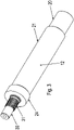
Figur 3 ist das zweite Wellenteil 12 in Schrägansicht dargestellt. - In der
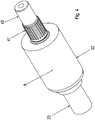
Figur 4 ist das erste Wellenteil 8 in Schrägansicht dargestellt. - In der
Figur 5 ist der Rotor eines zu dem Ausführungsbeispiel nachFigur 1 bis 4 ähnlichen Ausführungsbeispiels dargestellt, wobei das Rotorwellenteil 9 angeschnitten dargestellt ist. - Wie in den
Figuren 1 bis 4 gezeigt weist der Motor ein Statorgehäuse 1 auf, in welchem ein die Statorwicklung aufnehmendes Statorblechpaket 2 aufgenommen ist. Der Wickelkopf 5 ragt axial beidseitig über den vom Statorblechpaket 2 überdeckten axialen Bereich hervor. - Das Statorgehäuse 1 ist an seinem ersten axialen Endbereich mit einem Lagerschild 6 verbunden, welches ein erstes Lager 7 zur Lagerung des Rotors aufnimmt.
- Das Statorgehäuse 1 ist an seinem anderen axialen Endbereich mit einem Lagerschild 10 verbunden, welches ein zweites Lager 11 zur Lagerung des Rotors aufnimmt.
- Der Rotor ist aus einem Rotorwellenteil 9 gebildet, welches an seinen beiden axialen Endbereichen jeweils eine axial gerichtete Stufenbohrung aufweist, in welche jeweils ein am ersten Wellenteil 8 beziehungsweise am zweiten Wellenteil 12 ausgeformter Zapfenbereich eingesteckt ist.
- Das erste Wellenteil 8 weist einen Lagersitz 22 auf, auf dem das erste Lager 7 angeordnet ist. Außerdem ist der Zapfenbereich des ersten Wellenteils 8 an der dem Rotorwellenteil 9 zugewandten axialen Endbereich des ersten Wellenteils 8 angeordnet. Dabei weist der Zapfenbereich einen Verzahnungsbereich 41 und einen zwischen dem Verzahnungsbereich 41 und Lagersitz 22 angeordneten zylindrischen Bereich 40 auf.
- Am anderen axialen Endbereich des ersten Wellenteils 8 ist ein Verbindungsbereich 23 ausgebildet, der eine Passfedernut aufweist, so dass ein Verzahnungsteil, insbesondere Ritzel, mittels Passfederverbindung drehfest mit dem Verbindungsbereich 23 verbindbar ist.
- Das zweite Wellenteil 12 weist einen Lagersitz 24 auf, auf dem das zweite Lager 11 angeordnet ist. Außerdem ist der Zapfenbereich des zweiten Wellenteils 12 an der dem Rotorwellenteil 9 zugewandten axialen Endbereich des ersten Wellenteils 8 angeordnet. Dabei weist der Zapfenbereich einen Verzahnungsbereich 31 und einen zwischen dem Verzahnungsbereich 31 und Lagersitz 24 angeordneten zylindrischen Bereich 30 auf.
- Am anderen axialen Endbereich des zweiten Wellenteils 12 ist ein Verbindungsbereich 20 ausgebildet, der eine Passfedernut aufweist, so dass ein Lüfter mittels Passfederverbindung drehfest mit dem Verbindungsbereich 20 verbindbar ist. Alternativ oder zusätzlich ist hier auch ein Winkelsensor verbindbar zur Detektion der Winkelstellung des Rotors.
- Zwischen dem Lagersitz 24 und dem Verbindungsbereich 20 ist ein Beabstandungsbereich 21 angeordnet. Dieser ist optional auch mit einer Passfedernut ausstattbar, so dass ein Verzahnungsteil, insbesondere Mitnehmer, formschlüssig mit dem Wellenteil 12 verbindbar ist. Auf dem Verzahnungsteil ist ein Bremsbelagträger einer elektromagnetisch betätigbaren Bremse anordenbar, welcher drehfest mit dem Rotor aber axial verschiebbar anordenbar ist.
- Die Verzahnungsbereiche 31 und 41 sind als axial geformte Verzahnung ausführbar und/oder jeweils als gerändelte Bereiche ausführbar, insbesondere also so, dass die Verzahnung als Rändelung ausgeführt ist.
- Die jeweilige Stufenbohrung weist einen zylindrischen Bereich auf, in welchem der jeweilige zylindrische Bereich (30, 40) aufgenommen wird, und jeweils einen innenverzahnten Bereich, in welchen der jeweilige Verzahnungsbereich (31, 41) eingepresst wird. Bei diesem Einpressen erfolgt aber nur elastische Verformung, also keine Spanbildung.
- Vorzugswiese weist der zylindrische Bereich (30, 40) eine größere axiale Länge auf als die Verzahnungsbereiche (31, 41). Somit führt und zentriert der jeweilige zylindrische Bereich (30, 40) das jeweilige Wellenteil (8, 12) beim Einpressen der Verzahnungsbereiche (31, 41) in den jeweiligen außenverzahnten Bereich.
- Der Lagersitz 24 des zweiten Wellenteils 12 weist einen größeren Durchmesser auf als der zu ihm axial benachbarte Verzahnungsbereich 31. Der Lagersitz 24 des zweiten Wellenteils weist einen größeren Durchmesser auf als der auf der vom Verzahnungsbereich 31 axial abgewandten Seite des Lagersitzes 24 angeordnete Beabstandungsbereich 21.
- Der Beabstandungsbereich 21 wiest einen größeren Durchmesser auf als der Verbindungsbereich 20.
- Der Lagersitz 22 des ersten Wellenteils 8 weist einen größeren Durchmesser auf als der zu ihm axial benachbarte Verzahnungsbereich 41. Der Lagersitz 22 des ersten Wellenteils 8 weist einen größeren Durchmesser auf als der Verbindungsbereich 23, der auf der vom Verzahnungsbereich 41 axial abgewandten Seite des Lagersitzes 22.
- Das Rotorblechpaket 4 ist auf das Rotorwellenteil 9 aufgesteckt. Der Bereich der Berührung, also Berührbereich, zwischen Rotorblechpaket 4 und Rotorwellenteil 9 ist jedoch axial weniger ausgedehnt als das Rotorblechpaket 4.
- Denn das Rotorwellenteil 9 weist im Berührbereich einen größeren Durchmesser auf als in den axial beidseitig, angrenzenden Bereichen des Rotorwellenteils 9. Somit ist in diesen angrenzenden Bereichen jeweils ein Spalt (15, 16) zwischen Rotorblechpaket 4 und Rotorwellenteil 9 ausgebildet.
- Der Kurzschlusskäfig 3 ist vorzugsweise aus Aluminium und/oder Kupfer ausgeführt. Das Rotorblechpaket 4 ist vorzugsweise aus einem in axialer Richtung gebildeten Stapel von Einzelblechteilen gefertigt, welche vorzugsweise aus Stahlblech hergestellt sind.
- Der von der jeweiligen Stufenbohrung axial überdeckte Bereich ist beabstandet von dem vom Berührbereich axial überdeckten Bereich. Somit ist also ein axialer Abstand zwischen Stufenbohrung und Berührbereich vorhanden.
- Der von der jeweiligen Stufenbohrung axial überdeckte Bereich darf jedoch mit dem von dem jeweiligen benachbarten Spalt (15, 16) überdeckten axialen Bereich überlappen. In jedem Fall ist aber auch dann ein axialer Abstand zwischen Stufenbohrung und Berührbereich des Rotorblechpakets 4 mit dem Rotorwellenteil 9 vorhanden.
- Auf diese Weise werden Spannungen, die gegebenenfalls beim Verbinden der Wellenteile 8 und 12 mit dem Rotorwellenteil 9 entstehen, möglichst ferngehalten von dem Berührbereich, in welchem es wichtig ist, dass das Rotorwellenteil 9 eine möglichst präzise zylindrische Außenkontur aufweist.
- Außerdem ist für den Fall, dass die Wellenteile 8 und 12 nicht genau genug fluchten mit dem Rotorwellenteil 9 ein nachträgliches Verformen und somit Ausrichten der Wellenteile 8 und 12 zum Rotorwellenteil 9 hin ermöglicht, ohne dass die dabei entstehenden Spannungen einen störenden Einfluss auf das auf dem Berührbereich aufgenommene Rotorblechpaket 4 ausüben.
- Das Rotorblechpaket 4 ist auf den Berührbereich vorzugsweise thermisch aufgeschrumpft, also kraftschlüssig verbunden.
- Das erste Wellenteil 8 liegt an der Schnittkante 13 des Rotorwellenteils 9 an mit der am Ansatz des Zapfenbereichs angeordneten Stufe.
- Das zweite Wellenteil 12 liegt an der Schnittkante 14 des Rotorwellenteils 9 an mit der am Ansatz des Zapfenbereichs angeordneten Stufe.
- Durch die mehrteilige Ausführung des Rotors ist mit einer geringen Anzahl von Bauteilen eine hohe Varianz von Rotoren bereit stellbar.
- Wie in dem ähnlichen Rotor gemäß
Figur 5 gezeigt, ist der zylindrischer Bereich 40 des Zapfenbereichs des ersten Wellenteils 8 und der Verzahnungsbereich 41 des Zapfenbereichs des ersten Wellenteils 8 jeweils beabstandet vom Spalt 16, welcher axial zwischengeordnet ist zwischen dem zylindrischen Bereich 40 und dem Berührbereich des Statorblechpakets 4 mit dem Rotorwellenteil 9. - Ebenso der zylindrischer Bereich 30 des Zapfenbereichs des zweiten Wellenteils 12 und der Verzahnungsbereich 31 des Zapfenbereichs des zweiten Wellenteils 12 jeweils beabstandet vom Spalt 15, welcher axial zwischengeordnet ist zwischen dem zylindrischen Bereich 30 und dem Berührbereich des Statorblechpakets 4 mit dem Rotorwellenteil 9.
- Der Berührbereich fungiert also als Tragbereich für das Rotorblechpaket 4.
- Das erste Wellenteil 8 ist aus Stahl gefertigt. Das zweite Wellenteil 12 ist aus Stahl gefertigt. Das erste Rotorwellenteil 9 ist aus Stahl gefertigt.
- Bei weiteren erfindungsgemäßen Ausführungsbeispielen werden die zylindrischen Bereiche (30, 40) der Zapfenbereiche und/oder die Verzahnungsbereiche (31, 41) zusätzlich mit einer Spiralnut versehen. Auf diese Weise kann die beim Einpressen der Zapfenbereiche in die Stufenbohrung zusammengedrückte Luft entweichen und die Zentrierung beim Einpressen ist somit einfacher gewährleistbar.
-
- 1 Statorgehäuse
- 2 Statorblechpaket
- 3 Kurzschlusskäfig
- 4 Rotorblechpaket
- 5 Wickelkopf
- 6 Lagerschild
- 7 Lager
- 8 erstes Wellenteil
- 9 Rotorwellenteil
- 10 Lagerschild
- 11 Lager
- 12 zweites Wellenteil
- 13 Schnittkante
- 14 Schnittkante
- 15 Spalt
- 16 Spalt
- 20 Verbindungsbereich
- 21 Beabstandungsbereich
- 22 Lagersitz
- 23 Verbindungsbereich
- 24 Lagersitz
- 30 zylindrischer Bereich des Zapfenbereichs
- 31 Verzahnungsbereich des Zapfenbereichs
- 40 zylindrischer Bereich des Zapfenbereichs
- 41 Verzahnungsbereich des Zapfenbereichs
Claims (8)
- Elektromotor, umfassend einen Rotor,wobei der Rotor ein Rotorwellenteil (9) und ein erstes Wellenteil (8) und ein zweites Wellenteil (12) aufweist,wobei das Rotorwellenteil (9) axial zwischen dem ersten und dem zweiten Wellenteil (8, 12) angeordnet ist,wobei das erste Wellenteil (8) einen ersten Lagersitz (22) aufweist und mit dem Rotorwellenteil (9) drehfest verbunden ist,wobei das zweite Wellenteil (12) einen zweiten Lagersitz (24) aufweist und mit dem Rotorwellenteil (9) drehfest verbunden ist,wobei ein Rotorblechpaket (4) auf dem Rotorwellenteil (9) angeordnet ist, wobei der Berührbereich zwischen Rotorblechpaket (4) und Rotorwellenteil axial geringer ausgedehnt ist als das Rotorblechpaket (4),wobei zwischen dem Rotorblechpaket (4) und dem Rotorwellenteil (9) ein erster Spalt (15) angeordnet ist, welcher axial an den Berührbereich angrenzt,und wobei zwischen dem Rotorblechpaket (4) und dem Rotorwellenteil (9) ein zweiter Spalt (16) angeordnet ist, welcher axial an den Berührbereich angrenzt,wobei der erste Spalt (15) und der zweite Spalt (16) axial beidseitig des Berührungsbereichs angeordnet sind,wobei das erste Wellenteil (8) einen ersten Zapfenbereich aufweist, welcher in eine erste Ausnehmung des Rotorwellenteils (9) eingepresst ist,wobei das zweite Wellenteil (12) einen zweiten Zapfenbereich aufweist, welcher in eine zweite Ausnehmung des Rotorwellenteils (9) eingepresst ist,wobei der erste Zapfenbereich und der zweite Zapfenbereich jeweils axial zwischen dem Berührbereich und einem der Lagersitze (22, 24) angeordnet sind,wobei der vom Zapfenbereich des ersten Wellenteils (8) überdeckte axiale Bereich überlappt mit dem vom ersten Spalt überdeckten axialen Bereich und/oderaxial beabstandet ist von dem vom Berührbereich überdeckten axialen Bereich,wobei der vom Zapfenbereich des zweiten Wellenteils (12) überdeckte axiale Bereich überlappt mit dem vom zweiten Spalt überdeckten axialen Bereich und/oderaxial beabstandet ist von dem vom Berührbereich überdeckten axialen Bereich.
- Elektromotor nach Anspruch 1,
dadurch gekennzeichnet, dass
der Rotor über ein erstes Lager (7) in einem ersten Lagerschild (6) gelagert ist und über ein zweites Lager (11) in einem zweiten Lagerschild (10), wobei das erste und das zweite Lagerschild (6, 10) mit einem Statorgehäuse (1) verbunden sind, welches zwischen dem ersten und dem zweiten Lagerschild (6, 10) angeordnet ist. - Elektromotor nach mindestens einem der vorangegangenen Ansprüche,
dadurch gekennzeichnet, dassam ersten Lagersitz (22) ein erstes Lager (7) des Rotors angeordnet ist und am zweiten Lagersitz (24) ein zweites Lager (11) des Rotors,wobei das erste Lager (7) im ersten Lagerschild (6) aufgenommen ist und das zweite Lager (11) im zweiten Lagerschild (10). - Elektromotor nach mindestens einem der vorangegangenen Ansprüche,
dadurch gekennzeichnet, dass
im Statorgehäuse (1) ein Statorblechpaket (2) mit darin eingelegter Statorwicklung aufgenommen ist. - Elektromotor nach mindestens einem der vorangegangenen Ansprüche, dadurch gekennzeichnet, dassder erste Zapfenbereich einen Verzahnungsbereich (31), also verzahnten Bereich, und einen zylindrischen Bereich (30) aufweist, wobei der Verzahnungsbereich (31) in einen innenverzahnten Bereich der ersten Ausnehmung eingepresst ist, insbesondere unter elastischer Verformung,und/oderder zweite Zapfenbereich ebenfalls einen Verzahnungsbereich (41), also verzahnten Bereich, und einen zylindrischen Bereich (40) aufweist, wobei der Verzahnungsbereich (41) in einen innenverzahnten Bereich der zweiten Ausnehmung eingepresst ist, insbesondere unter elastischer Verformung.
- Elektromotor nach mindestens einem der vorangegangenen Ansprüche, dadurch gekennzeichnet, dass
ein Kurzschlusskäfig (3) im Rotorblechpaket (4) aufgenommen ist. - Elektromotor nach mindestens einem der vorangegangenen Ansprüche, dadurch gekennzeichnet, dass
das erste Wellenteil (8) einen Verbindungsbereich (20) aufweist, insbesondere welcher eine Passfedernut zur Verbindung mit einem Verzahnungsteil, insbesondere Ritzel, aufweist. - Elektromotor nach mindestens einem der vorangegangenen Ansprüche, dadurch gekennzeichnet, dass
das zweite Wellenteil (12) einen Verbindungsbereich (23) aufweist, insbesondere welcher eine Passfedernut zur Verbindung mit einem Lüfterrad und/oder mit einem Mitnehmer aufweist.
Applications Claiming Priority (2)
| Application Number | Priority Date | Filing Date | Title |
|---|---|---|---|
| DE102017007694 | 2017-08-16 | ||
| PCT/EP2018/025196 WO2019034285A1 (de) | 2017-08-16 | 2018-07-16 | Elektromotor, umfassend einen rotor |
Publications (2)
| Publication Number | Publication Date |
|---|---|
| EP3669444A1 EP3669444A1 (de) | 2020-06-24 |
| EP3669444B1 true EP3669444B1 (de) | 2022-11-30 |
Family
ID=62986037
Family Applications (1)
| Application Number | Title | Priority Date | Filing Date |
|---|---|---|---|
| EP18743682.9A Active EP3669444B1 (de) | 2017-08-16 | 2018-07-16 | Elektromotor, umfassend einen rotor |
Country Status (5)
| Country | Link |
|---|---|
| US (2) | US11211843B2 (de) |
| EP (1) | EP3669444B1 (de) |
| CN (1) | CN111033966B (de) |
| DE (1) | DE102018005573A1 (de) |
| WO (1) | WO2019034285A1 (de) |
Families Citing this family (2)
| Publication number | Priority date | Publication date | Assignee | Title |
|---|---|---|---|---|
| DE102022003341A1 (de) | 2021-09-24 | 2023-03-30 | Sew-Eurodrive Gmbh & Co Kg | Elektromotor mit Rotorwelle |
| DE102022200604A1 (de) | 2022-01-20 | 2023-07-20 | Mahle International Gmbh | Rotor für einen Elektromotor |
Family Cites Families (25)
| Publication number | Priority date | Publication date | Assignee | Title |
|---|---|---|---|---|
| CH27587A (de) | 1903-02-27 | 1904-01-31 | Bbc Brown Boveri & Cie | Rotor für elektrische Maschinen |
| US2427748A (en) * | 1945-07-09 | 1947-09-23 | Westinghouse Electric Corp | Bearing for vertical shafts |
| US3234419A (en) | 1962-01-15 | 1966-02-08 | Gen Electric | Cast rotor for a dynamoelectric machine |
| US3391291A (en) * | 1965-08-06 | 1968-07-02 | Eugene G. Benson | Electric motor construction |
| DE2548313A1 (de) | 1975-10-29 | 1977-05-05 | Bosch Gmbh Robert | Elektrische maschine mit klauenpolen |
| DE4205322A1 (de) | 1992-02-21 | 1993-08-26 | Schurr Stahlecker & Grill | Wellenkupplung fuer unterzylinder von streckwerken an spinnmaschinen |
| CN1083634A (zh) * | 1992-09-03 | 1994-03-09 | 冯建光 | 往复电动装置 |
| DE4240045C1 (de) | 1992-11-28 | 1994-02-03 | Licentia Gmbh | Elektromotor, insbesondere zum Antrieb von Kraftfahrzeugen |
| DE10051403A1 (de) | 2000-10-17 | 2002-06-13 | Minebea Co Ltd | Rotorbaugruppe für einen Elektromotor und Innenläufer-Elektromotor |
| DE10238336A1 (de) * | 2002-08-16 | 2004-02-26 | Flender Tübingen GmbH | Motorreihe |
| DE20307198U1 (de) * | 2003-05-08 | 2003-09-25 | Minebea Co.,Ltd., Kitasaku, Nagano | Rotor für einen Elektromotor |
| FR2905806B1 (fr) * | 2006-09-13 | 2008-12-26 | Valeo Equip Electr Moteur | Arbre de rotor a griffes, rotor a griffes equipe d'un tel arbre et machine electrique tournante equipee d'un tel rotor |
| FR2920837B1 (fr) * | 2007-09-10 | 2013-08-02 | Valeo Equip Electr Moteur | Machine electrique tournante, notamment un demarreur |
| DE102010031399A1 (de) * | 2010-07-15 | 2012-01-19 | Hilti Aktiengesellschaft | Rotor für einen Elektromotor, Elektromotor und Herstellungsverfahren für einen Elektromotor |
| DE102011006281A1 (de) * | 2011-03-29 | 2012-10-04 | Zf Friedrichshafen Ag | Elektrische Maschine |
| JP2013074736A (ja) | 2011-09-28 | 2013-04-22 | Toyota Motor Corp | 回転電機のロータ、および、これを用いた回転電機 |
| JP6069695B2 (ja) | 2012-11-02 | 2017-02-01 | 日産自動車株式会社 | モータ用ロータ |
| JP2015020257A (ja) * | 2013-07-22 | 2015-02-02 | 株式会社マキタ | 電動工具 |
| EP2854258B1 (de) | 2013-09-26 | 2021-01-20 | SKF Magnetic Mechatronics S.A.S. | Aufbau einer Permanentmagnet-Rotorwelle und Verfahren |
| CN103595211B (zh) * | 2013-11-19 | 2016-08-17 | 江苏航天动力机电有限公司 | 高速永磁同步电机三段转轴结构 |
| FR3034460B1 (fr) | 2015-04-01 | 2019-07-19 | Liebherr-Aerospace Toulouse Sas | Ensemble rotor et turbomachine tournant a tres grandes vitesses comportant un tel ensemble rotor |
| DE202015003200U1 (de) | 2015-05-01 | 2015-05-21 | Lothar Ginzel | Welle einer elektrischen Maschine |
| DE202015103013U1 (de) * | 2015-06-10 | 2016-09-14 | Baumüller Nürnberg GmbH | Elektrische Maschine |
| CN205647161U (zh) * | 2016-03-22 | 2016-10-12 | 台邦电机工业集团有限公司 | 一种转子轴及电动机 |
| CN212202817U (zh) * | 2020-04-17 | 2020-12-22 | 山东恒远工程机械有限公司 | 一种阶梯式工程机械轴 |
-
2018
- 2018-07-16 CN CN201880052603.2A patent/CN111033966B/zh active Active
- 2018-07-16 EP EP18743682.9A patent/EP3669444B1/de active Active
- 2018-07-16 US US16/639,973 patent/US11211843B2/en active Active
- 2018-07-16 WO PCT/EP2018/025196 patent/WO2019034285A1/de not_active Ceased
- 2018-07-16 DE DE102018005573.7A patent/DE102018005573A1/de active Pending
-
2021
- 2021-12-27 US US17/562,243 patent/US11652387B2/en active Active
Also Published As
| Publication number | Publication date |
|---|---|
| CN111033966B (zh) | 2022-11-08 |
| US11652387B2 (en) | 2023-05-16 |
| DE102018005573A1 (de) | 2019-02-21 |
| CN111033966A (zh) | 2020-04-17 |
| EP3669444A1 (de) | 2020-06-24 |
| WO2019034285A1 (de) | 2019-02-21 |
| US11211843B2 (en) | 2021-12-28 |
| US20220123622A1 (en) | 2022-04-21 |
| US20200195082A1 (en) | 2020-06-18 |
Similar Documents
| Publication | Publication Date | Title |
|---|---|---|
| DE102018200865B4 (de) | Rotor für eine elektrische Maschine | |
| DE60023782T2 (de) | Kleinstmotor und sein Herstellungsverfahren | |
| DE2138898A1 (de) | Regelbarer asynchronmotor mit einem mehrfach-rotorsystem | |
| DE10312614A1 (de) | Elektrische Maschine mit in den Stator integrierter Rotorlagerung | |
| DE3534333A1 (de) | Verfahren zur einstellung des axialspiels zwischen dem rotor und dem stator eines motors | |
| EP2169807B1 (de) | Blechpaketanordnung mit Krallenendblech | |
| EP2300719A1 (de) | Wellenanordnung für schnelldrehende wellen | |
| DE102020203483A1 (de) | Rotor eines Elektromotors | |
| EP3669444A1 (de) | Elektromotor, umfassend einen rotor | |
| EP3513486B1 (de) | Elektromotor mit verbesserter motorkühlung zum antrieb eines lüfters | |
| DE10230006A1 (de) | Asynchronmaschine | |
| EP3944470A1 (de) | Lagerschild | |
| DE2261956B2 (de) | Elektromotor, insbesondere zum Antrieb von Wischanlagen bei Kraftfahrzeugen | |
| DE202004003695U1 (de) | Hydrodynamisches Lagersystem zur Drehlagerung eines Spindelmotors | |
| EP3031963B1 (de) | Falschdrallspindel und falschdralleinheit | |
| DE4311242C2 (de) | Rotor für eine elektrische Maschine | |
| EP3626870B1 (de) | Spinnrotor mit einem halter zum rotieren einer rotortasse und verfahren zur herstellung einer pressverbindung zwischen einer rotortasse und einem halter | |
| DE102012101247B4 (de) | Elektromaschine | |
| DE102013019779A1 (de) | Stator für eine elektrische Maschine | |
| DE10150717A1 (de) | Montagevorrichtung für eine Brennkraftmaschine und Montageverfahren hierzu | |
| DE102019218196A1 (de) | Elektromotorisch angetriebenes Aggregat für ein Fahrzeug | |
| EP4089284B1 (de) | Nassläuferpumpe | |
| DE102022003341A1 (de) | Elektromotor mit Rotorwelle | |
| WO2023020734A1 (de) | Elektrische maschine umfassend einen ionisator | |
| EP4173116A1 (de) | Elektrische maschine und kraftfahrzeug-antriebseinheit |
Legal Events
| Date | Code | Title | Description |
|---|---|---|---|
| STAA | Information on the status of an ep patent application or granted ep patent |
Free format text: STATUS: UNKNOWN |
|
| STAA | Information on the status of an ep patent application or granted ep patent |
Free format text: STATUS: THE INTERNATIONAL PUBLICATION HAS BEEN MADE |
|
| PUAI | Public reference made under article 153(3) epc to a published international application that has entered the european phase |
Free format text: ORIGINAL CODE: 0009012 |
|
| STAA | Information on the status of an ep patent application or granted ep patent |
Free format text: STATUS: REQUEST FOR EXAMINATION WAS MADE |
|
| 17P | Request for examination filed |
Effective date: 20200316 |
|
| AK | Designated contracting states |
Kind code of ref document: A1 Designated state(s): AL AT BE BG CH CY CZ DE DK EE ES FI FR GB GR HR HU IE IS IT LI LT LU LV MC MK MT NL NO PL PT RO RS SE SI SK SM TR |
|
| AX | Request for extension of the european patent |
Extension state: BA ME |
|
| DAV | Request for validation of the european patent (deleted) | ||
| DAX | Request for extension of the european patent (deleted) | ||
| STAA | Information on the status of an ep patent application or granted ep patent |
Free format text: STATUS: EXAMINATION IS IN PROGRESS |
|
| 17Q | First examination report despatched |
Effective date: 20210312 |
|
| GRAP | Despatch of communication of intention to grant a patent |
Free format text: ORIGINAL CODE: EPIDOSNIGR1 |
|
| STAA | Information on the status of an ep patent application or granted ep patent |
Free format text: STATUS: GRANT OF PATENT IS INTENDED |
|
| INTG | Intention to grant announced |
Effective date: 20220713 |
|
| GRAS | Grant fee paid |
Free format text: ORIGINAL CODE: EPIDOSNIGR3 |
|
| GRAA | (expected) grant |
Free format text: ORIGINAL CODE: 0009210 |
|
| STAA | Information on the status of an ep patent application or granted ep patent |
Free format text: STATUS: THE PATENT HAS BEEN GRANTED |
|
| AK | Designated contracting states |
Kind code of ref document: B1 Designated state(s): AL AT BE BG CH CY CZ DE DK EE ES FI FR GB GR HR HU IE IS IT LI LT LU LV MC MK MT NL NO PL PT RO RS SE SI SK SM TR |
|
| REG | Reference to a national code |
Ref country code: CH Ref legal event code: EP Ref country code: GB Ref legal event code: FG4D Free format text: NOT ENGLISH |
|
| REG | Reference to a national code |
Ref country code: AT Ref legal event code: REF Ref document number: 1535449 Country of ref document: AT Kind code of ref document: T Effective date: 20221215 |
|
| REG | Reference to a national code |
Ref country code: IE Ref legal event code: FG4D Free format text: LANGUAGE OF EP DOCUMENT: GERMAN |
|
| REG | Reference to a national code |
Ref country code: DE Ref legal event code: R096 Ref document number: 502018011159 Country of ref document: DE |
|
| REG | Reference to a national code |
Ref country code: LT Ref legal event code: MG9D |
|
| REG | Reference to a national code |
Ref country code: NL Ref legal event code: MP Effective date: 20221130 |
|
| PG25 | Lapsed in a contracting state [announced via postgrant information from national office to epo] |
Ref country code: SE Free format text: LAPSE BECAUSE OF FAILURE TO SUBMIT A TRANSLATION OF THE DESCRIPTION OR TO PAY THE FEE WITHIN THE PRESCRIBED TIME-LIMIT Effective date: 20221130 Ref country code: PT Free format text: LAPSE BECAUSE OF FAILURE TO SUBMIT A TRANSLATION OF THE DESCRIPTION OR TO PAY THE FEE WITHIN THE PRESCRIBED TIME-LIMIT Effective date: 20230331 Ref country code: NO Free format text: LAPSE BECAUSE OF FAILURE TO SUBMIT A TRANSLATION OF THE DESCRIPTION OR TO PAY THE FEE WITHIN THE PRESCRIBED TIME-LIMIT Effective date: 20230228 Ref country code: LT Free format text: LAPSE BECAUSE OF FAILURE TO SUBMIT A TRANSLATION OF THE DESCRIPTION OR TO PAY THE FEE WITHIN THE PRESCRIBED TIME-LIMIT Effective date: 20221130 Ref country code: FI Free format text: LAPSE BECAUSE OF FAILURE TO SUBMIT A TRANSLATION OF THE DESCRIPTION OR TO PAY THE FEE WITHIN THE PRESCRIBED TIME-LIMIT Effective date: 20221130 Ref country code: ES Free format text: LAPSE BECAUSE OF FAILURE TO SUBMIT A TRANSLATION OF THE DESCRIPTION OR TO PAY THE FEE WITHIN THE PRESCRIBED TIME-LIMIT Effective date: 20221130 |
|
| PG25 | Lapsed in a contracting state [announced via postgrant information from national office to epo] |
Ref country code: RS Free format text: LAPSE BECAUSE OF FAILURE TO SUBMIT A TRANSLATION OF THE DESCRIPTION OR TO PAY THE FEE WITHIN THE PRESCRIBED TIME-LIMIT Effective date: 20221130 Ref country code: PL Free format text: LAPSE BECAUSE OF FAILURE TO SUBMIT A TRANSLATION OF THE DESCRIPTION OR TO PAY THE FEE WITHIN THE PRESCRIBED TIME-LIMIT Effective date: 20221130 Ref country code: LV Free format text: LAPSE BECAUSE OF FAILURE TO SUBMIT A TRANSLATION OF THE DESCRIPTION OR TO PAY THE FEE WITHIN THE PRESCRIBED TIME-LIMIT Effective date: 20221130 Ref country code: IS Free format text: LAPSE BECAUSE OF FAILURE TO SUBMIT A TRANSLATION OF THE DESCRIPTION OR TO PAY THE FEE WITHIN THE PRESCRIBED TIME-LIMIT Effective date: 20230330 Ref country code: HR Free format text: LAPSE BECAUSE OF FAILURE TO SUBMIT A TRANSLATION OF THE DESCRIPTION OR TO PAY THE FEE WITHIN THE PRESCRIBED TIME-LIMIT Effective date: 20221130 Ref country code: GR Free format text: LAPSE BECAUSE OF FAILURE TO SUBMIT A TRANSLATION OF THE DESCRIPTION OR TO PAY THE FEE WITHIN THE PRESCRIBED TIME-LIMIT Effective date: 20230301 |
|
| PG25 | Lapsed in a contracting state [announced via postgrant information from national office to epo] |
Ref country code: NL Free format text: LAPSE BECAUSE OF FAILURE TO SUBMIT A TRANSLATION OF THE DESCRIPTION OR TO PAY THE FEE WITHIN THE PRESCRIBED TIME-LIMIT Effective date: 20221130 |
|
| PG25 | Lapsed in a contracting state [announced via postgrant information from national office to epo] |
Ref country code: SM Free format text: LAPSE BECAUSE OF FAILURE TO SUBMIT A TRANSLATION OF THE DESCRIPTION OR TO PAY THE FEE WITHIN THE PRESCRIBED TIME-LIMIT Effective date: 20221130 Ref country code: RO Free format text: LAPSE BECAUSE OF FAILURE TO SUBMIT A TRANSLATION OF THE DESCRIPTION OR TO PAY THE FEE WITHIN THE PRESCRIBED TIME-LIMIT Effective date: 20221130 Ref country code: EE Free format text: LAPSE BECAUSE OF FAILURE TO SUBMIT A TRANSLATION OF THE DESCRIPTION OR TO PAY THE FEE WITHIN THE PRESCRIBED TIME-LIMIT Effective date: 20221130 Ref country code: DK Free format text: LAPSE BECAUSE OF FAILURE TO SUBMIT A TRANSLATION OF THE DESCRIPTION OR TO PAY THE FEE WITHIN THE PRESCRIBED TIME-LIMIT Effective date: 20221130 Ref country code: CZ Free format text: LAPSE BECAUSE OF FAILURE TO SUBMIT A TRANSLATION OF THE DESCRIPTION OR TO PAY THE FEE WITHIN THE PRESCRIBED TIME-LIMIT Effective date: 20221130 |
|
| PG25 | Lapsed in a contracting state [announced via postgrant information from national office to epo] |
Ref country code: SK Free format text: LAPSE BECAUSE OF FAILURE TO SUBMIT A TRANSLATION OF THE DESCRIPTION OR TO PAY THE FEE WITHIN THE PRESCRIBED TIME-LIMIT Effective date: 20221130 Ref country code: AL Free format text: LAPSE BECAUSE OF FAILURE TO SUBMIT A TRANSLATION OF THE DESCRIPTION OR TO PAY THE FEE WITHIN THE PRESCRIBED TIME-LIMIT Effective date: 20221130 |
|
| REG | Reference to a national code |
Ref country code: DE Ref legal event code: R097 Ref document number: 502018011159 Country of ref document: DE |
|
| PLBE | No opposition filed within time limit |
Free format text: ORIGINAL CODE: 0009261 |
|
| STAA | Information on the status of an ep patent application or granted ep patent |
Free format text: STATUS: NO OPPOSITION FILED WITHIN TIME LIMIT |
|
| 26N | No opposition filed |
Effective date: 20230831 |
|
| PG25 | Lapsed in a contracting state [announced via postgrant information from national office to epo] |
Ref country code: SI Free format text: LAPSE BECAUSE OF FAILURE TO SUBMIT A TRANSLATION OF THE DESCRIPTION OR TO PAY THE FEE WITHIN THE PRESCRIBED TIME-LIMIT Effective date: 20221130 |
|
| PG25 | Lapsed in a contracting state [announced via postgrant information from national office to epo] |
Ref country code: MC Free format text: LAPSE BECAUSE OF FAILURE TO SUBMIT A TRANSLATION OF THE DESCRIPTION OR TO PAY THE FEE WITHIN THE PRESCRIBED TIME-LIMIT Effective date: 20221130 |
|
| PG25 | Lapsed in a contracting state [announced via postgrant information from national office to epo] |
Ref country code: MC Free format text: LAPSE BECAUSE OF FAILURE TO SUBMIT A TRANSLATION OF THE DESCRIPTION OR TO PAY THE FEE WITHIN THE PRESCRIBED TIME-LIMIT Effective date: 20221130 |
|
| REG | Reference to a national code |
Ref country code: CH Ref legal event code: PL |
|
| REG | Reference to a national code |
Ref country code: BE Ref legal event code: MM Effective date: 20230731 |
|
| PG25 | Lapsed in a contracting state [announced via postgrant information from national office to epo] |
Ref country code: LU Free format text: LAPSE BECAUSE OF NON-PAYMENT OF DUE FEES Effective date: 20230716 |
|
| GBPC | Gb: european patent ceased through non-payment of renewal fee |
Effective date: 20230716 |
|
| PG25 | Lapsed in a contracting state [announced via postgrant information from national office to epo] |
Ref country code: LU Free format text: LAPSE BECAUSE OF NON-PAYMENT OF DUE FEES Effective date: 20230716 |
|
| REG | Reference to a national code |
Ref country code: IE Ref legal event code: MM4A |
|
| PG25 | Lapsed in a contracting state [announced via postgrant information from national office to epo] |
Ref country code: GB Free format text: LAPSE BECAUSE OF NON-PAYMENT OF DUE FEES Effective date: 20230716 Ref country code: CH Free format text: LAPSE BECAUSE OF NON-PAYMENT OF DUE FEES Effective date: 20230731 |
|
| PG25 | Lapsed in a contracting state [announced via postgrant information from national office to epo] |
Ref country code: BE Free format text: LAPSE BECAUSE OF NON-PAYMENT OF DUE FEES Effective date: 20230731 |
|
| PG25 | Lapsed in a contracting state [announced via postgrant information from national office to epo] |
Ref country code: IE Free format text: LAPSE BECAUSE OF NON-PAYMENT OF DUE FEES Effective date: 20230716 |
|
| PG25 | Lapsed in a contracting state [announced via postgrant information from national office to epo] |
Ref country code: IE Free format text: LAPSE BECAUSE OF NON-PAYMENT OF DUE FEES Effective date: 20230716 |
|
| REG | Reference to a national code |
Ref country code: AT Ref legal event code: MM01 Ref document number: 1535449 Country of ref document: AT Kind code of ref document: T Effective date: 20230716 |
|
| PG25 | Lapsed in a contracting state [announced via postgrant information from national office to epo] |
Ref country code: AT Free format text: LAPSE BECAUSE OF NON-PAYMENT OF DUE FEES Effective date: 20230716 |
|
| PG25 | Lapsed in a contracting state [announced via postgrant information from national office to epo] |
Ref country code: AT Free format text: LAPSE BECAUSE OF NON-PAYMENT OF DUE FEES Effective date: 20230716 |
|
| PG25 | Lapsed in a contracting state [announced via postgrant information from national office to epo] |
Ref country code: BG Free format text: LAPSE BECAUSE OF FAILURE TO SUBMIT A TRANSLATION OF THE DESCRIPTION OR TO PAY THE FEE WITHIN THE PRESCRIBED TIME-LIMIT Effective date: 20221130 |
|
| PG25 | Lapsed in a contracting state [announced via postgrant information from national office to epo] |
Ref country code: BG Free format text: LAPSE BECAUSE OF FAILURE TO SUBMIT A TRANSLATION OF THE DESCRIPTION OR TO PAY THE FEE WITHIN THE PRESCRIBED TIME-LIMIT Effective date: 20221130 |
|
| PGFP | Annual fee paid to national office [announced via postgrant information from national office to epo] |
Ref country code: FR Payment date: 20250610 Year of fee payment: 8 |
|
| PG25 | Lapsed in a contracting state [announced via postgrant information from national office to epo] |
Ref country code: CY Free format text: LAPSE BECAUSE OF FAILURE TO SUBMIT A TRANSLATION OF THE DESCRIPTION OR TO PAY THE FEE WITHIN THE PRESCRIBED TIME-LIMIT; INVALID AB INITIO Effective date: 20180716 |
|
| PG25 | Lapsed in a contracting state [announced via postgrant information from national office to epo] |
Ref country code: HU Free format text: LAPSE BECAUSE OF FAILURE TO SUBMIT A TRANSLATION OF THE DESCRIPTION OR TO PAY THE FEE WITHIN THE PRESCRIBED TIME-LIMIT; INVALID AB INITIO Effective date: 20180716 |
|
| PGFP | Annual fee paid to national office [announced via postgrant information from national office to epo] |
Ref country code: DE Payment date: 20250731 Year of fee payment: 8 |
|
| PGFP | Annual fee paid to national office [announced via postgrant information from national office to epo] |
Ref country code: IT Payment date: 20250710 Year of fee payment: 8 |
|
| PG25 | Lapsed in a contracting state [announced via postgrant information from national office to epo] |
Ref country code: TR Free format text: LAPSE BECAUSE OF FAILURE TO SUBMIT A TRANSLATION OF THE DESCRIPTION OR TO PAY THE FEE WITHIN THE PRESCRIBED TIME-LIMIT Effective date: 20221130 |