EP3668286B1 - Abdichtsystem für elektrisches gerät - Google Patents
Abdichtsystem für elektrisches gerät Download PDFInfo
- Publication number
- EP3668286B1 EP3668286B1 EP19209553.7A EP19209553A EP3668286B1 EP 3668286 B1 EP3668286 B1 EP 3668286B1 EP 19209553 A EP19209553 A EP 19209553A EP 3668286 B1 EP3668286 B1 EP 3668286B1
- Authority
- EP
- European Patent Office
- Prior art keywords
- electrical equipment
- stopper
- plate
- item
- base
- Prior art date
- Legal status (The legal status is an assumption and is not a legal conclusion. Google has not performed a legal analysis and makes no representation as to the accuracy of the status listed.)
- Active
Links
- 238000007789 sealing Methods 0.000 title claims description 44
- 230000006835 compression Effects 0.000 claims description 8
- 238000007906 compression Methods 0.000 claims description 8
- 238000000034 method Methods 0.000 claims description 8
- 230000002093 peripheral effect Effects 0.000 claims description 2
- 238000003780 insertion Methods 0.000 description 4
- 230000037431 insertion Effects 0.000 description 4
- 239000000463 material Substances 0.000 description 4
- 238000010586 diagram Methods 0.000 description 3
- 229920001971 elastomer Polymers 0.000 description 2
- 239000007788 liquid Substances 0.000 description 2
- 230000007257 malfunction Effects 0.000 description 2
- 230000001419 dependent effect Effects 0.000 description 1
- 239000000806 elastomer Substances 0.000 description 1
- 230000000149 penetrating effect Effects 0.000 description 1
Images


Classifications
-
- H—ELECTRICITY
- H01—ELECTRIC ELEMENTS
- H01R—ELECTRICALLY-CONDUCTIVE CONNECTIONS; STRUCTURAL ASSOCIATIONS OF A PLURALITY OF MUTUALLY-INSULATED ELECTRICAL CONNECTING ELEMENTS; COUPLING DEVICES; CURRENT COLLECTORS
- H01R13/00—Details of coupling devices of the kinds covered by groups H01R12/70 or H01R24/00 - H01R33/00
- H01R13/46—Bases; Cases
- H01R13/52—Dustproof, splashproof, drip-proof, waterproof, or flameproof cases
- H01R13/5205—Sealing means between cable and housing, e.g. grommet
-
- H—ELECTRICITY
- H05—ELECTRIC TECHNIQUES NOT OTHERWISE PROVIDED FOR
- H05K—PRINTED CIRCUITS; CASINGS OR CONSTRUCTIONAL DETAILS OF ELECTRIC APPARATUS; MANUFACTURE OF ASSEMBLAGES OF ELECTRICAL COMPONENTS
- H05K5/00—Casings, cabinets or drawers for electric apparatus
- H05K5/06—Hermetically-sealed casings
- H05K5/069—Other details of the casing, e.g. wall structure, passage for a connector, a cable, a shaft
-
- H—ELECTRICITY
- H02—GENERATION; CONVERSION OR DISTRIBUTION OF ELECTRIC POWER
- H02G—INSTALLATION OF ELECTRIC CABLES OR LINES, OR OF COMBINED OPTICAL AND ELECTRIC CABLES OR LINES
- H02G15/00—Cable fittings
- H02G15/013—Sealing means for cable inlets
-
- H—ELECTRICITY
- H02—GENERATION; CONVERSION OR DISTRIBUTION OF ELECTRIC POWER
- H02K—DYNAMO-ELECTRIC MACHINES
- H02K5/00—Casings; Enclosures; Supports
- H02K5/04—Casings or enclosures characterised by the shape, form or construction thereof
- H02K5/22—Auxiliary parts of casings not covered by groups H02K5/06-H02K5/20, e.g. shaped to form connection boxes or terminal boxes
-
- H—ELECTRICITY
- H05—ELECTRIC TECHNIQUES NOT OTHERWISE PROVIDED FOR
- H05K—PRINTED CIRCUITS; CASINGS OR CONSTRUCTIONAL DETAILS OF ELECTRIC APPARATUS; MANUFACTURE OF ASSEMBLAGES OF ELECTRICAL COMPONENTS
- H05K5/00—Casings, cabinets or drawers for electric apparatus
- H05K5/02—Details
- H05K5/03—Covers
-
- H—ELECTRICITY
- H02—GENERATION; CONVERSION OR DISTRIBUTION OF ELECTRIC POWER
- H02K—DYNAMO-ELECTRIC MACHINES
- H02K5/00—Casings; Enclosures; Supports
- H02K5/04—Casings or enclosures characterised by the shape, form or construction thereof
- H02K5/10—Casings or enclosures characterised by the shape, form or construction thereof with arrangements for protection from ingress, e.g. water or fingers
Definitions
- the present invention relates to the field of electrical equipment, and more particularly electrical machines used for vehicles.
- the invention aims in particular to allow the sealing of electrical equipment, in particular for a vehicle.
- THE figure 1 And 2 represent electrical equipment 100 conforming to the state of the art.
- Such electrical equipment 100 comprises a frame in which is arranged a cavity 110, for example cylindrical, comprising the active part of the electrical equipment 100.
- the cavity 110 is closed by a cover 160.
- the electrical equipment 100 comprises a bearing 120, at the interface between the exterior and the interior of the cavity 110.
- Said bearing 120 comprises a housing, also closed by the cover 160 , said housing being intended to house sensors connected inside the cavity 110.
- a cable 130 connected to a sensor or to a device located in the housing or inside the cavity 110 connects the electrical equipment 100 to a second electrical equipment.
- the cable 130 makes it possible, for example, to transmit to this second electrical equipment information measured by sensors present in the housing, concerning the active part of the electrical equipment 100.
- This information makes it possible, for example, to control the electrical equipment 100 more efficiently and/or to detect a malfunction relating to this electrical equipment 100.
- the cable 130 must in particular reach the cavity 110 and the housing arranged in the bearing 120 in order to connect the sensors and the second external electrical equipment to said cavity 110. To this end, the cable 130 interferes between said cover 160 and the bearing 120.
- the cable 130 is inserted into a rubber seal 140, said seal 140 being adapted to then be inserted and adjusted in a passage 150 provided at the periphery of the bearing 120.
- the cover 160 in particular provided with its own joint, is fixed to the bearing 120 and covers the joint 140 inserted in the passage 150.
- the seal of the cover 160 therefore comes to rest against the seal 140 provided to allow the passage of the cable 130 and fitted in the passage 150.
- the seal of the cover 160 makes it possible to seal the cavity 110 in order to protect the active part of the electrical equipment 100.
- the seal comprises a double junction.
- first junction J1 is located between the bearing 120 and the seal 140 and a second junction J2 is located between the seal 140 and the bearing 120.
- the elements located on each side of the first junction J1 and of the second junction J2 are composed of different materials. There is therefore a difference in compression between the cover seal 160 and the bearing 120 on the one hand, where there is contact between a "hard” surface and a “soft” surface (that of the cover seal 160) with respect to the compression between the lid seal 160 and the seal 140, where there is contact between two "soft” surfaces.
- This difference in compression can cause sealing problems in the cavity 110, in particular because of runoff of liquid by capillarity along at least one cable 130 or between the seal 140 and the cover seal 160.
- the document JP 2012075253 A describes a sealed cable passage for electrical equipment but it does not ensure the sealing of the electrical equipment in question.
- the document JP2005045904 describes a joint structure
- the document US2005026489 describes a cable sealing system for a connector
- the document CA481856 describes closure members of devices for sealing the ends of electric cables.
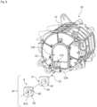
- electrical equipment 10 for a vehicle has a frame in which is arranged a cavity 11, for example cylindrical, comprising an active part of the electrical equipment 10.
- the electrical equipment 10 is an electrical machine.
- the electrical equipment 10 can be an inverter, a DC-DC converter or an electrical charger.
- the cavity 11 is delimited by a bearing 12.
- a first housing 12A and a second housing 12B are arranged in the bearing 12.
- a cover 16 is placed and fixed on the bearing 12 so as to close said housings 12A, 12B.
- Said first housing 12A makes it possible to receive a sealing system 20 making a sealed electrical connection according to an example of the invention.
- Said first housing 12A may be square, as shown in figure 5 , or any other geometric shape.
- a peripheral wall of said first housing 12A may have a notch 122, configured to allow the passage of one or more electrical wires associated with the sealing system 20, from the exterior of the electrical equipment 10 to the interior. electrical equipment 10 when mounting the sealing system 20 in the electrical equipment 10, in particular in the first housing 12A.
- Said second housing 12B comprises sensors for example making it possible to retrieve information characterizing the active part of the electrical equipment 10.
- the second housing 12B can include a position sensor making it possible to know the position of the rotor relative to the stator and a temperature sensor measuring the temperature inside the cavity 11 (not shown).
- the cover 16 closes the electrical equipment 10, in particular the first housing 12A and the second housing 12B in a sealed manner.
- the electrical equipment 10 also comprises one or more electrical wires 13 penetrating inside the electrical equipment 10 at the level of the housing 12A of the bearing 12.
- each electrical wire 13 is either connected between the active part and another electrical equipment external to the electrical equipment 10 via the first housing 12A, or connected between a sensor and another electrical equipment external to the electrical equipment 10, via the first housing 12A.
- the electrical wire 13 allows the exchange of data between the electrical equipment 10 and other electrical equipment and in particular makes it possible, for example, to transmit to these other electrical equipment information concerning the active part of the electrical equipment 10 , measured by sensors, in particular present in the second housing 12B. This information makes it possible, for example, to control the electrical equipment 10 more efficiently and/or to detect a malfunction concerning this electrical equipment 10.
- the electrical equipment 10 may be a rotating electrical machine and the external electrical equipment may be an inverter making it possible to control said rotating electrical machine.
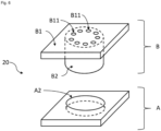
- FIG. 6 there is shown a first embodiment of a sealing system 20 making it possible to ensure the sealing of electrical equipment 10, as presented previously, in particular in the zone of the passage of the electrical wire 13 from the outside towards inside electrical equipment 10.
- said sealing system 20 comprises two distinct elements.
- the sealing system includes a base A and a cap B.
- the base A is presented as a rigid and not very flexible part, for example in plastic, of geometric shape adapted to be inserted in an adjusted manner in the bottom of the first housing 12A of the bearing 12.
- base A is a square-shaped plastic part.
- said base A comprises a first plate A1 comprising a through hole A2, for example cylindrical and positioned at the center of base A. The entire edge of the through hole A2 is continuously included in one face of said first plate A1.
- the stopper B is a part made of a flexible material, for example an elastomer part, the stopper B having a greater flexibility than the flexibility of the base A.
- Said stopper B comprises a second plate B1 whose dimensions are adapted to allow the insertion of the plug B into the first housing 12A, in particular to allow said insertion, for example so that the plug B fills the entire first housing 12A.
- the second tray B1 comprises at least one through hole B11, as shown in figure 6 , the at least one hole B11 is intended to allow the passage of at least one electrical wire 13.
- the second tray B1 may include several holes B11. According to the embodiment presented, the number of holes B11 is equal to the number of electric wires 13.
- the holes B11 of the cap B have a cross section smaller than the cross section of each electric wire 13 passing through the sealing system 20.
- the diameter of each hole B11 is less than the diameter of each electrical wire 13. In this way, when an electrical wire 13 is inserted into a hole B11, no liquid can flow by capillarity along this electrical wire 13 through this hole B11. Part of the sealing of the cavity 11 is therefore ensured at the junction between each electrical wire 13 and each hole B11 associated with said electrical wire 13.
- the cap B also comprises a protruding part B2, the shape of which is adapted so that the protruding part B2 is mounted by force in the empty space formed inside the orifice A2 of the base A. in force, the dimensions of the projecting part B2 are equal to or greater than those of the orifice A2.
- the projecting part B2 of the plug B is inserted, like a plug, into the orifice A2.
- one face of the second plate B1 of the cap B comes against a face of the first plate A1 of the base A.
- the base A allows the compression of the second tray B1 of cap B thanks to cover 16; once plug B has been inserted into base A, the protruding part B2 of the plug is thus compressed in the orifice A2 of base A.
- the cover 16 of I ⁇ electrical equipment 10 makes it possible to cover the second housing 12B in a sealed manner by means of a seal (not shown) disposed between the bearing 12 and the cover 16 of the electrical equipment 10, in particular on the periphery of the cover 16.
- the lid 16 also comprises a through opening 16-1, the edges of which are configured to bear against the second plate B1 of the stopper B, in particular at the periphery of the second plate B1, and thus ensure sealing at the level of the opening 16-1. A portion of said cover 16 thus comes to bear on said plate B1 of cap B against a closed line describing the periphery of said plate B1 of cap B.
- the cap B being made of a more flexible material than the base A, the support of the lid 16 on the second plate B1 of the cap B ensures a compression of the second plate B1 of the cap B between the edges of the opening 16 -1 and the first plate A1 of the base A, and therefore a seal at the level of the passage of the electrical wire 13. Unlike the prior art, the contact between the cover 16 and the bearing 12 is uniform, which improves the sealing.
- FIG 8 there is shown the electrical equipment 10 as well as a sealing system 20, making it possible to describe a method for sealing an electrical equipment 10; to this end, a sealing system 20 is attached to the electrical equipment 10, in accordance with a first embodiment of the invention.
- the projecting part B2 of the cap B is inserted into the orifice A2 of the base A.
- the cap B and the base A constitute an assembly whose parts are integral to each other.
- each electrical wire 13 is inserted into a hole B11 passing through the cap B.
- the first and the second step can be reversed.
- the assembly formed by the plug B, the base A and the electric wire(s) 13, is inserted into the first housing 12A of the bearing 12, so that the base A is inserted at the bottom of said first housing 12A and so that the electric wire(s) 13 have access to the interior of the electrical equipment 10, in particular to the second housing 12B by passing through the notch 122 of the bearing 12.
- the assembly between these various elements is therefore simple and fast.
- the cover 16 is fixed over this assembly and the compression of the second plate B1, placed between the cover 16 and the base A, makes it possible to seal the electrical equipment 10 at the level of the electrical connection. electrical equipment 10.
- This assembly also makes it possible to ensure a double seal at the level of the electrical connection of the electrical equipment 10.
- the insertion of each electrical wire 13 into a hole B11 makes it possible to ensure the sealing of the wires electrical 13.
- the sealing is also ensured by the compression of the edges of the opening 16-1 of the lid 16 on the external part of the second plate B1 of the stopper B against the base A, itself inserted in the first housing 12A.
- the present invention allows a decoupling between the tightness of the passage of the electrical wires 13 through the cap B and that of the electrical equipment 10.
- the base A is molded onto the cap B, with which it forms a one-piece assembly, that is to say integrally in one piece.
- the base A can also be molded or not with the electrical wire 13.
- the first housing 12A can have a notch 122, as in the first embodiment.
- the sealing process of the second embodiment of the sealing system 20 comprises the second, third and fourth steps of the sealing process of the first embodiment.
- the base A is made from material of the bearing 12.
- the base A is formed by a bottom of the first housing 12A.
- the bearing 12 does not have a notch 122 as in the first embodiment.
- the sealing process comprises a first step during which the projecting part B2 of the cap B is inserted into the orifice A2 of the base A and a second step during which the cover 16 is fixed by above landing 12.
Landscapes
- Engineering & Computer Science (AREA)
- Microelectronics & Electronic Packaging (AREA)
- Power Engineering (AREA)
- Connector Housings Or Holding Contact Members (AREA)
- Installation Of Indoor Wiring (AREA)
- Insertion, Bundling And Securing Of Wires For Electric Apparatuses (AREA)
- Cable Accessories (AREA)
Claims (12)
- Abdichtsystem (20), welches dafür ausgelegt ist, die Herstellung einer dichten elektrischen Verbindung auf einer Seite eines elektrischen Gerätes (10) zu ermöglichen, wobei das Abdichtsystem (20) umfasst:einen Sockel (A), der eine erste Platte (A1) umfasst, wobei die erste Platte (A1) eine durchgehende Bohrung (A2) umfasst, wobei der gesamte Rand der durchgehenden Bohrung (A2) vollständig in einer Seite der ersten Platte (A1) enthalten ist,einen Stopfen (B), der eine zweite Platte (B1) und einen von der Platte (B1) des Stopfens (B) vorstehenden Teil (B2) umfasst, wobei der vorstehende Teil (B2) so gestaltet ist, dass er in die Bohrung (A2) des Sockels (A) passt, wobei eine Seite der zweiten Platte (B1) des Stopfens (B) an einer Seite der ersten Platte (A1) des Sockels (A) zur Anlage kommt, wobei die zweite Platte (B1) und der vorstehende Teil (B2) wenigstens ein durchgehendes Loch (B11) umfassen, das dazu bestimmt ist, die Durchführung wenigstens eines elektrischen Kabels (13) zu ermöglichen, wobei das wenigstens eine Loch (B11) einen Querschnitt aufweist, der kleiner als derjenige des wenigstens einen elektrischen Kabels (13) ist,wobei der Stopfen (B) eine Nachgiebigkeit aufweist, die größer als die Nachgiebigkeit des Sockels (A) ist, so dass, wenn das Abdichtsystem (20) auf einer Seite des elektrischen Gerätes (10) positioniert wird und ein Anlegen der Platte des Stopfens (B) an die Platte des Sockels (A) erfolgt, der Unterschied in der Nachgiebigkeit eine Spannungsbeaufschlagung der zweiten Platte (B1) des Stopfens (B) auf der ersten Platte (A1) des Sockels (A) ermöglicht, um ein Zusammendrücken der zweiten Platte (B1) des Stopfens (B) sicherzustellen, das zur Dichtigkeit des elektrischen Gerätes (10) beiträgt, wobei der vorstehende Teil (B2) des Stopfens (B) dafür ausgelegt ist, unter Kraftaufwand in der Bohrung (A2) des Sockels (A) angebracht zu werden, und die Abmessungen des vorstehenden Teils (B2) gleich denjenigen oder größer als diejenigen der Bohrung (A2) sind,wobei das Abdichtsystem (20) dafür ausgelegt ist, in eine erste Aufnahme (12A) mit entsprechenden Abmessungen eingesetzt zu werden, die an der Seite des elektrischen Gerätes (10) angeordnet ist, so dass eine Abdeckung (16) des elektrischen Gerätes (10) dann die Anlage der zweiten Platte (B1) des Stopfens (B) an der ersten Platte (A1) des Sockels (A) sicherstellt.
- Abdichtsystem (20) nach Anspruch 1, wobei der Sockel (A) und der Stopfen (B) unabhängige Teile sind.
- Abdichtsystem (20) nach einem der vorhergehenden Ansprüche, wobei der Sockel (A) und der Stopfen (B) eine unabhängige Baugruppe bilden, die dafür ausgelegt ist, an einen Rahmen des elektrischen Gerätes (10) angesetzt zu werden.
- Elektrisches Gerät (10), welches ein Abdichtsystem nach einem der vorhergehenden Ansprüche sowie eine Abdeckung (16), die an die Seite des elektrischen Gerätes (10) so angesetzt ist, dass sie das elektrische Gerät (10) wenigstens teilweise verschließt, umfasst, wobei ein Abschnitt der Abdeckung (16) die Anlage an der zweiten Platte (B1) des Stopfens (B) wenigstens an einer geschlossenen Linie sicherstellt, die den Umfang der zweiten Platte (B1) des Stopfens (B) beschreibt.
- Elektrisches Gerät (10) nach dem vorhergehenden Anspruch, wobei die Abdeckung (16) eine durchgehende Öffnung (16-1) umfasst, deren Ränder durchgehend wenigstens an der geschlossenen Linie zur Anlage kommen, die den Umfang der zweiten Platte (B1) des Stopfens (B) beschreibt, so dass sie das wenigstens eine Loch (B11) der zweiten Platte (B1) des Stopfens (B) umgeben.
- Elektrisches Gerät (10) nach einem der Ansprüche 4 bis 5, welches ein Lager (12) umfasst, das einen Teil des Rahmens des elektrischen Gerätes (10) bildet, wobei das Lager (12) eine erste Aufnahme (12A) aufweist, die das Abdichtsystem (20) enthält.
- Elektrisches Gerät nach dem vorhergehenden Anspruch, wobei der Sockel (A) ein von dem Lager (12) verschiedenes Teil ist und in der ersten Aufnahme (12A) angebracht ist.
- Elektrisches Gerät nach dem vorhergehenden Anspruch, wobei eine Umfangswand der ersten Aufnahme (12A) eine Aussparung (122) aufweist, die sich von einer Öffnung der ersten Aufnahme (12A) aus erstreckt, durch welche der Stopfen (B) in der ersten Aufnahme (12A) aufgenommen wird, wobei die Aussparung (122) dafür ausgelegt ist, bei einer Anbringung des Stopfens (B) in der ersten Aufnahme (12A) die Durchführung des wenigstens einen elektrischen Kabels (13) ins Innere des elektrischen Gerätes (10) zu ermöglichen.
- Elektrisches Gerät (10) nach Anspruch 6, welches ein Abdichtsystem (20) nach einem der Ansprüche 1 bis 2 umfasst, wobei der Sockel (A) mit dem Lager (12) fest verbunden ist oder mit dem Lager (12) stoffschlüssig verbunden ist.
- Elektrisches Gerät (10) nach dem vorhergehenden Anspruch, wobei der Sockel (A) in einem Boden der ersten Aufnahme (12A) enthalten ist, die den Stopfen (B) aufnimmt.
- Elektrisches Gerät (10) nach Anspruch 6, welches ein Abdichtsystem (20) nach Anspruch 3 umfasst.
- Verfahren zur Abdichtung eines elektrischen Gerätes (10) nach einem der Ansprüche 6 bis 11, wobei das Verfahren dazu bestimmt ist, einen Hohlraum (11) abzudichten, der in einem Lager (12) angeordnet ist, das einen Teil des Rahmens des elektrischen Gerätes (10) bildet, wobei das Verfahren Schritte umfasst:des Einsetzens des vorstehenden Teils (B2) des Stopfens (B) in die Bohrung (A2) des Sockels (A),des Einsetzens jedes Kabels (13) des Kabelbaums (13) in ein Loch (B11) des Stopfens (B),des Einsetzens der Baugruppe, die den Stopfen (B), den Sockel (A) und den Kabelbaum (13) umfasst, in die erste Aufnahme (12A) des Lagers (12),der Befestigung der Abdeckung (16) auf dem Lager (12), so dass die Ränder der durchgehenden Öffnung (16-1) der Abdeckung (16) an der zweiten Platte (B1) des Stopfens (B) anliegen.
Applications Claiming Priority (1)
| Application Number | Priority Date | Filing Date | Title |
|---|---|---|---|
| FR1872974A FR3090221B1 (fr) | 2018-12-14 | 2018-12-14 | Système d’étanchéité pour un équipement électrique |
Publications (2)
| Publication Number | Publication Date |
|---|---|
| EP3668286A1 EP3668286A1 (de) | 2020-06-17 |
| EP3668286B1 true EP3668286B1 (de) | 2023-05-10 |
Family
ID=66676668
Family Applications (1)
| Application Number | Title | Priority Date | Filing Date |
|---|---|---|---|
| EP19209553.7A Active EP3668286B1 (de) | 2018-12-14 | 2019-11-15 | Abdichtsystem für elektrisches gerät |
Country Status (4)
| Country | Link |
|---|---|
| US (1) | US11128085B2 (de) |
| EP (1) | EP3668286B1 (de) |
| CN (1) | CN111328234B (de) |
| FR (1) | FR3090221B1 (de) |
Families Citing this family (2)
| Publication number | Priority date | Publication date | Assignee | Title |
|---|---|---|---|---|
| TWI651034B (zh) * | 2018-06-01 | 2019-02-11 | 和碩聯合科技股份有限公司 | 一種防水結構 |
| CN113531220A (zh) * | 2020-04-15 | 2021-10-22 | 康普技术有限责任公司 | 缆线密封装置和缆线密封系统 |
Citations (1)
| Publication number | Priority date | Publication date | Assignee | Title |
|---|---|---|---|---|
| EP2856568B1 (de) * | 2012-05-31 | 2018-07-11 | Delphi International Operations Luxembourg S.à r.l. | Einzeldrahtdichtung zum abdichten eines elektrischen kabels in einer öffnung einer anschlussklemme |
Family Cites Families (14)
| Publication number | Priority date | Publication date | Assignee | Title |
|---|---|---|---|---|
| CA481856A (en) * | 1952-03-18 | Donald Clothier George | Closure members for devices for sealing the ends of electric cables | |
| JPH08315903A (ja) * | 1995-05-19 | 1996-11-29 | Toyota Motor Corp | シール部材及びシール構造 |
| JPH08335420A (ja) * | 1995-06-07 | 1996-12-17 | Sumitomo Wiring Syst Ltd | グロメットの取付構造 |
| JP4176854B2 (ja) * | 1997-10-14 | 2008-11-05 | 藤倉ゴム工業株式会社 | 止水装置 |
| JP4075718B2 (ja) * | 2003-07-28 | 2008-04-16 | 三菱自動車工業株式会社 | シール構造 |
| DE10334518A1 (de) * | 2003-07-29 | 2005-02-17 | Harting Electric Gmbh & Co. Kg | Kabelabdichtung für einen Steckverbinder |
| JP2008028267A (ja) * | 2006-07-24 | 2008-02-07 | Fanuc Ltd | 電気回路ユニットのシール構造 |
| CN101154798B (zh) * | 2006-09-30 | 2012-03-21 | 拉普工程公司 | 缆线馈通装置及缆线馈通系统 |
| JP5314540B2 (ja) * | 2009-09-01 | 2013-10-16 | 矢崎総業株式会社 | コネクタ |
| JP2012075253A (ja) * | 2010-09-29 | 2012-04-12 | Hitachi Industrial Equipment Systems Co Ltd | 電線の防水装置及び防水方法、制御装置、建設用機械 |
| JP2013201053A (ja) * | 2012-03-26 | 2013-10-03 | Hitachi Cable Ltd | シール部材及びコネクタ |
| JP5880804B1 (ja) * | 2014-07-22 | 2016-03-09 | Nok株式会社 | グロメット |
| CN106207597B (zh) * | 2016-07-29 | 2019-03-01 | 中航光电科技股份有限公司 | 一种导线过孔出线结构 |
| CN206992854U (zh) * | 2017-03-16 | 2018-02-09 | 苏州双航机电有限公司 | 一种电机的防水结构 |
-
2018
- 2018-12-14 FR FR1872974A patent/FR3090221B1/fr active Active
-
2019
- 2019-11-15 EP EP19209553.7A patent/EP3668286B1/de active Active
- 2019-12-10 CN CN201911259651.1A patent/CN111328234B/zh active Active
- 2019-12-13 US US16/713,294 patent/US11128085B2/en active Active
Patent Citations (1)
| Publication number | Priority date | Publication date | Assignee | Title |
|---|---|---|---|---|
| EP2856568B1 (de) * | 2012-05-31 | 2018-07-11 | Delphi International Operations Luxembourg S.à r.l. | Einzeldrahtdichtung zum abdichten eines elektrischen kabels in einer öffnung einer anschlussklemme |
Also Published As
| Publication number | Publication date |
|---|---|
| CN111328234A (zh) | 2020-06-23 |
| US11128085B2 (en) | 2021-09-21 |
| FR3090221B1 (fr) | 2022-03-25 |
| EP3668286A1 (de) | 2020-06-17 |
| FR3090221A1 (fr) | 2020-06-19 |
| US20200194927A1 (en) | 2020-06-18 |
| CN111328234B (zh) | 2023-07-25 |
Similar Documents
| Publication | Publication Date | Title |
|---|---|---|
| EP3668286B1 (de) | Abdichtsystem für elektrisches gerät | |
| FR2935449A1 (fr) | Unite de montage de capteur de temperature | |
| FR2924277A1 (fr) | Connecteur a blindage contre les ondes electromagnetiques | |
| FR3050078B1 (fr) | Connecteur pyrotechnique | |
| EP2086081B1 (de) | Isolierscheibe gegen Elektrizität zur Unterstützung eines linearen Leiters und diese Scheibe umfassende elektrische Einheit | |
| FR2837921A1 (fr) | Capteur de pression et procede de fabrication de ce dernier | |
| EP3499193A1 (de) | Vorrichtung zum messen eines physikalischen parameters einer flüssigkeit eines kraftfahrzeugskreises | |
| FR3081264A1 (fr) | Dispositif de serrage de cable pour connecteur electrique etanche et connecteur electrique | |
| FR2711393A1 (fr) | Système comprenant une prise de température notamment sur tubulure plastique. | |
| EP1489713A1 (de) | Dichte Wanddurchführungsvorrichtung | |
| EP1251616B1 (de) | Abdichtung für elektrisches Kabel | |
| EP2546614A1 (de) | Sensor- oder Detektorvorrichtung mit einem perfektionierten Kabelführungsstöpsel | |
| WO2013021119A2 (fr) | Dispositif de connexion electrique, ensemble comprenant un tel dispositif et une carte electronique et procede de connexion electrique d'une carte electronique | |
| FR2822947A1 (fr) | Capteur et procede pour sa fabrication | |
| EP0562970B1 (de) | Zusammenbau eines Ringkernes mit Spule | |
| EP2690734B1 (de) | Dichtungsfuge für Kabeldurchführung | |
| EP1531255B1 (de) | Dichtungsanordnung einer Einspritzdüsenbohrung | |
| FR2707002A1 (en) | Improved screened electrical sensor | |
| FR3076609A1 (fr) | Capteur angulaire | |
| EP1649472B1 (de) | Elektromagnetisches ventil, verfahren zum anbringen einer solenoidspule an dem elektromagnetischen ventil und verfahren zum ablösen der solenoidspule von diesem elektromagnetischen ventil | |
| FR2936201A1 (fr) | Motoreducteur notamment d'essuie-glace de vehicule automobile | |
| EP3578849B1 (de) | Aktive hydraulische schwingungsdämpfende vorrichtung und fahrzeug, das eine solche aktive hydraulische schwingungsdämpfende vorrichtung umfasst | |
| FR3045718A1 (fr) | Dispositif de traversee etanche d'une cloison de turbomachine | |
| FR3131114A1 (fr) | Connecteur avec joint d’étanchéité amélioré, assemblage d’étanchéité et procédé de montage d’un câble avec cet assemblage d’étanchéité | |
| EP2272135B1 (de) | Einrichtung zur verhinderung der erzeugung eines elektrischen bogens zwischen zwei leitfähigen elementen |
Legal Events
| Date | Code | Title | Description |
|---|---|---|---|
| PUAI | Public reference made under article 153(3) epc to a published international application that has entered the european phase |
Free format text: ORIGINAL CODE: 0009012 |
|
| STAA | Information on the status of an ep patent application or granted ep patent |
Free format text: STATUS: THE APPLICATION HAS BEEN PUBLISHED |
|
| AK | Designated contracting states |
Kind code of ref document: A1 Designated state(s): AL AT BE BG CH CY CZ DE DK EE ES FI FR GB GR HR HU IE IS IT LI LT LU LV MC MK MT NL NO PL PT RO RS SE SI SK SM TR |
|
| AX | Request for extension of the european patent |
Extension state: BA ME |
|
| STAA | Information on the status of an ep patent application or granted ep patent |
Free format text: STATUS: REQUEST FOR EXAMINATION WAS MADE |
|
| 17P | Request for examination filed |
Effective date: 20200924 |
|
| RBV | Designated contracting states (corrected) |
Designated state(s): AL AT BE BG CH CY CZ DE DK EE ES FI FR GB GR HR HU IE IS IT LI LT LU LV MC MK MT NL NO PL PT RO RS SE SI SK SM TR |
|
| STAA | Information on the status of an ep patent application or granted ep patent |
Free format text: STATUS: EXAMINATION IS IN PROGRESS |
|
| 17Q | First examination report despatched |
Effective date: 20220107 |
|
| RAP3 | Party data changed (applicant data changed or rights of an application transferred) |
Owner name: VALEO EAUTOMOTIVE GERMANY GMBH |
|
| GRAP | Despatch of communication of intention to grant a patent |
Free format text: ORIGINAL CODE: EPIDOSNIGR1 |
|
| STAA | Information on the status of an ep patent application or granted ep patent |
Free format text: STATUS: GRANT OF PATENT IS INTENDED |
|
| INTG | Intention to grant announced |
Effective date: 20221209 |
|
| GRAS | Grant fee paid |
Free format text: ORIGINAL CODE: EPIDOSNIGR3 |
|
| GRAA | (expected) grant |
Free format text: ORIGINAL CODE: 0009210 |
|
| STAA | Information on the status of an ep patent application or granted ep patent |
Free format text: STATUS: THE PATENT HAS BEEN GRANTED |
|
| RBV | Designated contracting states (corrected) |
Designated state(s): AL AT BE BG CH CY CZ DE DK EE ES FI GB GR HR HU IE IS IT LI LT LU LV MC MK MT NL NO PL PT RO RS SE SI SK SM TR |
|
| AK | Designated contracting states |
Kind code of ref document: B1 Designated state(s): AL AT BE BG CH CY CZ DE DK EE ES FI GB GR HR HU IE IS IT LI LT LU LV MC MK MT NL NO PL PT RO RS SE SI SK SM TR |
|
| REG | Reference to a national code |
Ref country code: GB Ref legal event code: FG4D Free format text: NOT ENGLISH |
|
| REG | Reference to a national code |
Ref country code: AT Ref legal event code: REF Ref document number: 1568055 Country of ref document: AT Kind code of ref document: T Effective date: 20230515 Ref country code: CH Ref legal event code: EP |
|
| REG | Reference to a national code |
Ref country code: DE Ref legal event code: R096 Ref document number: 602019028670 Country of ref document: DE |
|
| REG | Reference to a national code |
Ref country code: IE Ref legal event code: FG4D Free format text: LANGUAGE OF EP DOCUMENT: FRENCH |
|
| P01 | Opt-out of the competence of the unified patent court (upc) registered |
Effective date: 20230528 |
|
| REG | Reference to a national code |
Ref country code: LT Ref legal event code: MG9D |
|
| REG | Reference to a national code |
Ref country code: NL Ref legal event code: MP Effective date: 20230510 |
|
| REG | Reference to a national code |
Ref country code: AT Ref legal event code: MK05 Ref document number: 1568055 Country of ref document: AT Kind code of ref document: T Effective date: 20230510 |
|
| PG25 | Lapsed in a contracting state [announced via postgrant information from national office to epo] |
Ref country code: SE Free format text: LAPSE BECAUSE OF FAILURE TO SUBMIT A TRANSLATION OF THE DESCRIPTION OR TO PAY THE FEE WITHIN THE PRESCRIBED TIME-LIMIT Effective date: 20230510 Ref country code: PT Free format text: LAPSE BECAUSE OF FAILURE TO SUBMIT A TRANSLATION OF THE DESCRIPTION OR TO PAY THE FEE WITHIN THE PRESCRIBED TIME-LIMIT Effective date: 20230911 Ref country code: NO Free format text: LAPSE BECAUSE OF FAILURE TO SUBMIT A TRANSLATION OF THE DESCRIPTION OR TO PAY THE FEE WITHIN THE PRESCRIBED TIME-LIMIT Effective date: 20230810 Ref country code: NL Free format text: LAPSE BECAUSE OF FAILURE TO SUBMIT A TRANSLATION OF THE DESCRIPTION OR TO PAY THE FEE WITHIN THE PRESCRIBED TIME-LIMIT Effective date: 20230510 Ref country code: ES Free format text: LAPSE BECAUSE OF FAILURE TO SUBMIT A TRANSLATION OF THE DESCRIPTION OR TO PAY THE FEE WITHIN THE PRESCRIBED TIME-LIMIT Effective date: 20230510 Ref country code: AT Free format text: LAPSE BECAUSE OF FAILURE TO SUBMIT A TRANSLATION OF THE DESCRIPTION OR TO PAY THE FEE WITHIN THE PRESCRIBED TIME-LIMIT Effective date: 20230510 |
|
| PG25 | Lapsed in a contracting state [announced via postgrant information from national office to epo] |
Ref country code: RS Free format text: LAPSE BECAUSE OF FAILURE TO SUBMIT A TRANSLATION OF THE DESCRIPTION OR TO PAY THE FEE WITHIN THE PRESCRIBED TIME-LIMIT Effective date: 20230510 Ref country code: PL Free format text: LAPSE BECAUSE OF FAILURE TO SUBMIT A TRANSLATION OF THE DESCRIPTION OR TO PAY THE FEE WITHIN THE PRESCRIBED TIME-LIMIT Effective date: 20230510 Ref country code: LV Free format text: LAPSE BECAUSE OF FAILURE TO SUBMIT A TRANSLATION OF THE DESCRIPTION OR TO PAY THE FEE WITHIN THE PRESCRIBED TIME-LIMIT Effective date: 20230510 Ref country code: LT Free format text: LAPSE BECAUSE OF FAILURE TO SUBMIT A TRANSLATION OF THE DESCRIPTION OR TO PAY THE FEE WITHIN THE PRESCRIBED TIME-LIMIT Effective date: 20230510 Ref country code: IS Free format text: LAPSE BECAUSE OF FAILURE TO SUBMIT A TRANSLATION OF THE DESCRIPTION OR TO PAY THE FEE WITHIN THE PRESCRIBED TIME-LIMIT Effective date: 20230910 Ref country code: HR Free format text: LAPSE BECAUSE OF FAILURE TO SUBMIT A TRANSLATION OF THE DESCRIPTION OR TO PAY THE FEE WITHIN THE PRESCRIBED TIME-LIMIT Effective date: 20230510 Ref country code: GR Free format text: LAPSE BECAUSE OF FAILURE TO SUBMIT A TRANSLATION OF THE DESCRIPTION OR TO PAY THE FEE WITHIN THE PRESCRIBED TIME-LIMIT Effective date: 20230811 |
|
| PG25 | Lapsed in a contracting state [announced via postgrant information from national office to epo] |
Ref country code: FI Free format text: LAPSE BECAUSE OF FAILURE TO SUBMIT A TRANSLATION OF THE DESCRIPTION OR TO PAY THE FEE WITHIN THE PRESCRIBED TIME-LIMIT Effective date: 20230510 |
|
| PG25 | Lapsed in a contracting state [announced via postgrant information from national office to epo] |
Ref country code: SK Free format text: LAPSE BECAUSE OF FAILURE TO SUBMIT A TRANSLATION OF THE DESCRIPTION OR TO PAY THE FEE WITHIN THE PRESCRIBED TIME-LIMIT Effective date: 20230510 |
|
| PG25 | Lapsed in a contracting state [announced via postgrant information from national office to epo] |
Ref country code: SM Free format text: LAPSE BECAUSE OF FAILURE TO SUBMIT A TRANSLATION OF THE DESCRIPTION OR TO PAY THE FEE WITHIN THE PRESCRIBED TIME-LIMIT Effective date: 20230510 Ref country code: SK Free format text: LAPSE BECAUSE OF FAILURE TO SUBMIT A TRANSLATION OF THE DESCRIPTION OR TO PAY THE FEE WITHIN THE PRESCRIBED TIME-LIMIT Effective date: 20230510 Ref country code: RO Free format text: LAPSE BECAUSE OF FAILURE TO SUBMIT A TRANSLATION OF THE DESCRIPTION OR TO PAY THE FEE WITHIN THE PRESCRIBED TIME-LIMIT Effective date: 20230510 Ref country code: EE Free format text: LAPSE BECAUSE OF FAILURE TO SUBMIT A TRANSLATION OF THE DESCRIPTION OR TO PAY THE FEE WITHIN THE PRESCRIBED TIME-LIMIT Effective date: 20230510 Ref country code: DK Free format text: LAPSE BECAUSE OF FAILURE TO SUBMIT A TRANSLATION OF THE DESCRIPTION OR TO PAY THE FEE WITHIN THE PRESCRIBED TIME-LIMIT Effective date: 20230510 Ref country code: CZ Free format text: LAPSE BECAUSE OF FAILURE TO SUBMIT A TRANSLATION OF THE DESCRIPTION OR TO PAY THE FEE WITHIN THE PRESCRIBED TIME-LIMIT Effective date: 20230510 |
|
| PGFP | Annual fee paid to national office [announced via postgrant information from national office to epo] |
Ref country code: DE Payment date: 20231107 Year of fee payment: 5 |
|
| REG | Reference to a national code |
Ref country code: DE Ref legal event code: R097 Ref document number: 602019028670 Country of ref document: DE |
|
| PLBE | No opposition filed within time limit |
Free format text: ORIGINAL CODE: 0009261 |
|
| STAA | Information on the status of an ep patent application or granted ep patent |
Free format text: STATUS: NO OPPOSITION FILED WITHIN TIME LIMIT |
|
| 26N | No opposition filed |
Effective date: 20240213 |
|
| PG25 | Lapsed in a contracting state [announced via postgrant information from national office to epo] |
Ref country code: SI Free format text: LAPSE BECAUSE OF FAILURE TO SUBMIT A TRANSLATION OF THE DESCRIPTION OR TO PAY THE FEE WITHIN THE PRESCRIBED TIME-LIMIT Effective date: 20230510 |