EP3668286B1 - Sealing system for electrical equipment - Google Patents
Sealing system for electrical equipment Download PDFInfo
- Publication number
- EP3668286B1 EP3668286B1 EP19209553.7A EP19209553A EP3668286B1 EP 3668286 B1 EP3668286 B1 EP 3668286B1 EP 19209553 A EP19209553 A EP 19209553A EP 3668286 B1 EP3668286 B1 EP 3668286B1
- Authority
- EP
- European Patent Office
- Prior art keywords
- electrical equipment
- stopper
- plate
- item
- base
- Prior art date
- Legal status (The legal status is an assumption and is not a legal conclusion. Google has not performed a legal analysis and makes no representation as to the accuracy of the status listed.)
- Active
Links
- 238000007789 sealing Methods 0.000 title claims description 44
- 230000006835 compression Effects 0.000 claims description 8
- 238000007906 compression Methods 0.000 claims description 8
- 238000000034 method Methods 0.000 claims description 8
- 230000002093 peripheral effect Effects 0.000 claims description 2
- 238000003780 insertion Methods 0.000 description 4
- 230000037431 insertion Effects 0.000 description 4
- 239000000463 material Substances 0.000 description 4
- 238000010586 diagram Methods 0.000 description 3
- 229920001971 elastomer Polymers 0.000 description 2
- 239000007788 liquid Substances 0.000 description 2
- 230000007257 malfunction Effects 0.000 description 2
- 230000001419 dependent effect Effects 0.000 description 1
- 239000000806 elastomer Substances 0.000 description 1
- 230000000149 penetrating effect Effects 0.000 description 1
Images


Classifications
-
- H—ELECTRICITY
- H01—ELECTRIC ELEMENTS
- H01R—ELECTRICALLY-CONDUCTIVE CONNECTIONS; STRUCTURAL ASSOCIATIONS OF A PLURALITY OF MUTUALLY-INSULATED ELECTRICAL CONNECTING ELEMENTS; COUPLING DEVICES; CURRENT COLLECTORS
- H01R13/00—Details of coupling devices of the kinds covered by groups H01R12/70 or H01R24/00 - H01R33/00
- H01R13/46—Bases; Cases
- H01R13/52—Dustproof, splashproof, drip-proof, waterproof, or flameproof cases
- H01R13/5205—Sealing means between cable and housing, e.g. grommet
-
- H—ELECTRICITY
- H05—ELECTRIC TECHNIQUES NOT OTHERWISE PROVIDED FOR
- H05K—PRINTED CIRCUITS; CASINGS OR CONSTRUCTIONAL DETAILS OF ELECTRIC APPARATUS; MANUFACTURE OF ASSEMBLAGES OF ELECTRICAL COMPONENTS
- H05K5/00—Casings, cabinets or drawers for electric apparatus
- H05K5/06—Hermetically-sealed casings
- H05K5/069—Other details of the casing, e.g. wall structure, passage for a connector, a cable, a shaft
-
- H—ELECTRICITY
- H02—GENERATION; CONVERSION OR DISTRIBUTION OF ELECTRIC POWER
- H02G—INSTALLATION OF ELECTRIC CABLES OR LINES, OR OF COMBINED OPTICAL AND ELECTRIC CABLES OR LINES
- H02G15/00—Cable fittings
- H02G15/013—Sealing means for cable inlets
-
- H—ELECTRICITY
- H02—GENERATION; CONVERSION OR DISTRIBUTION OF ELECTRIC POWER
- H02K—DYNAMO-ELECTRIC MACHINES
- H02K5/00—Casings; Enclosures; Supports
- H02K5/04—Casings or enclosures characterised by the shape, form or construction thereof
- H02K5/22—Auxiliary parts of casings not covered by groups H02K5/06-H02K5/20, e.g. shaped to form connection boxes or terminal boxes
-
- H—ELECTRICITY
- H05—ELECTRIC TECHNIQUES NOT OTHERWISE PROVIDED FOR
- H05K—PRINTED CIRCUITS; CASINGS OR CONSTRUCTIONAL DETAILS OF ELECTRIC APPARATUS; MANUFACTURE OF ASSEMBLAGES OF ELECTRICAL COMPONENTS
- H05K5/00—Casings, cabinets or drawers for electric apparatus
- H05K5/02—Details
- H05K5/03—Covers
-
- H—ELECTRICITY
- H02—GENERATION; CONVERSION OR DISTRIBUTION OF ELECTRIC POWER
- H02K—DYNAMO-ELECTRIC MACHINES
- H02K5/00—Casings; Enclosures; Supports
- H02K5/04—Casings or enclosures characterised by the shape, form or construction thereof
- H02K5/10—Casings or enclosures characterised by the shape, form or construction thereof with arrangements for protection from ingress, e.g. water or fingers
Landscapes
- Engineering & Computer Science (AREA)
- Microelectronics & Electronic Packaging (AREA)
- Power Engineering (AREA)
- Connector Housings Or Holding Contact Members (AREA)
- Installation Of Indoor Wiring (AREA)
- Insertion, Bundling And Securing Of Wires For Electric Apparatuses (AREA)
- Cable Accessories (AREA)
Description
La présente invention concerne le domaine des équipements électriques, et plus particulièrement des machines électriques utilisées pour des véhicules.The present invention relates to the field of electrical equipment, and more particularly electrical machines used for vehicles.
L'invention vise notamment à permettre l'étanchéité d'un équipement électrique, notamment pour véhicule.The invention aims in particular to allow the sealing of electrical equipment, in particular for a vehicle.
Les
La cavité 110 est fermée par un couvercle 160. L'équipement électrique 100 comprend un palier 120, à l'interface entre l'extérieur et l'intérieur de la cavité 110. Ledit palier 120 comprend un logement, également fermé par le couvercle 160, ledit logement étant destiné à loger des capteurs reliés à l'intérieur de la cavité 110.The
Toujours en référence aux
Ces informations permettent par exemple de piloter plus efficacement l'équipement électrique 100 et/ou de détecter un dysfonctionnement relatif à cet équipement électrique 100.This information makes it possible, for example, to control the
De manière connue, le câble 130 doit notamment atteindre la cavité 110 et le logement aménagé dans le palier 120 afin de connecter les capteurs et le deuxième équipement électrique extérieur à ladite cavité 110. À cette fin, le câble 130 s'immisce entre ledit couvercle 160 et le palier 120.In known manner, the
Pour cela, en référence aux
Le joint du couvercle 160 permet d'assurer l'étanchéité de la cavité 110 afin de protéger la partie active de l'équipement électrique 100. Cependant, dans le cas présent, le joint comprend une double jonction.The seal of the
En effet, une première jonction J1 est située entre le palier 120 et le joint 140 et une deuxième jonction J2 est située entre le joint 140 et le palier 120.Indeed, a first junction J1 is located between the
Les éléments situés de chaque côté de la première jonction J1 et de la deuxième jonction J2 sont composés de matériaux différents. Il y a donc une différence de compression entre le joint du couvercle 160 et le palier 120 d'une part, où l'on a un contact entre une surface « dure » et une surface « souple » (celle du joint du couvercle 160) par rapport à la compression entre le joint du couvercle 160 et le joint 140, où l'on a un contact entre deux surfaces « souples ». Cette différence de compression peut engendrer des problèmes d'étanchéité dans la cavité 110, notamment à cause de ruissellements de liquide par capillarité le long d'au moins un câble 130 ou entre le joint 140 et le joint du couvercle 160.The elements located on each side of the first junction J1 and of the second junction J2 are composed of different materials. There is therefore a difference in compression between the
Ceci représente un inconvénient majeur puisque la cavité 110 doit être impérativement étanche pour éviter tout risque de détérioration d'un élément de la partie active de l'équipement électrique 100.This represents a major drawback since the
Une autre solution possible à ce problème technique est notamment d'installer des connecteurs sur la paroi de la cavité 110, qui permettent d'assurer l'étanchéité de la cavité 110 lorsqu'au moins un câble 130 est installé dans ledit connecteur. Cependant, cette solution est très coûteuse, environ une dizaine d'euros par connecteur.Another possible solution to this technical problem is in particular to install connectors on the wall of the
Le document
Il existe donc le besoin d'une solution économique permettant d'assurer l'étanchéité de la cavité lorsqu'un câble traverse ladite paroi.There is therefore a need for an economical solution making it possible to seal the cavity when a cable passes through said wall.
L'invention est définie par les revendications indépendantes. Des modes de réalisation préférés sont définis par les revendications dépendantes.The invention is defined by the independent claims. Preferred embodiments are defined by the dependent claims.
L'invention sera mieux comprise à la lecture de la description qui va suivre, et se référant aux dessins annexés donnés à titre d'exemples dans lesquels des références identiques sont données à des objets semblables et sur lesquels :
-
Fig. 1 (déjà commentée) illustre un schéma d'un équipement électrique selon l'état de l'art ; -
Fig. 2 (déjà commentée) illustre un schéma d'un équipement électrique selon l'état de l'art ; -
Fig. 3 (déjà commentée) illustre schématiquement un passage aménagé à la périphérie d'un palier d'équipement électrique selon l'état de l'art ; -
Fig. 4 (déjà commentée) illustre schématiquement un joint d'étanchéité placé dans un passage représenté à lafigure 3 selon l'état de l'art ; -
Fig. 5 représente le schéma d'un équipement électrique selon l'invention ; -
Fig. 6 illustre un système d'étanchéité selon l'invention ; -
Fig. 7 représente un équipement électrique et un système d'étanchéité selon un premier mode de réalisation de l'invention ; -
Fig. 8 représente un équipement électrique et un système d'étanchéité selon le premier mode de réalisation de l'invention ; -
Fig. 9 représente un équipement électrique et un système d'étanchéité selon un deuxième mode de réalisation de l'invention ; -
Fig. 10 représente un équipement électrique et un système d'étanchéité selon un troisième mode de réalisation de l'invention.
-
Fig. 1 (already commented) illustrates a diagram of electrical equipment according to the state of the art; -
Fig. 2 (already commented) illustrates a diagram of electrical equipment according to the state of the art; -
Fig. 3 (already commented on) schematically illustrates a passage arranged at the periphery of an electrical equipment bearing according to the state of the art; -
Fig. 4 (already commented) schematically illustrates a seal placed in a passage shown inpicture 3 according to the state of the art; -
Fig. 5 represents the diagram of electrical equipment according to the invention; -
Fig. 6 illustrates a sealing system according to the invention; -
Fig. 7 represents electrical equipment and a sealing system according to a first embodiment of the invention; -
Fig. 8 represents electrical equipment and a sealing system according to the first embodiment of the invention; -
Fig. 9 represents electrical equipment and a sealing system according to a second embodiment of the invention; -
Fig. 10 represents electrical equipment and a sealing system according to a third embodiment of the invention.
Il faut noter que les figures exposent l'invention de manière détaillée pour mettre en oeuvre l'invention, lesdites figures pouvant bien entendu servir à mieux définir l'invention le cas échéant.It should be noted that the figures expose the invention in detail to implement the invention, said figures can of course be used to better define the invention if necessary.
En référence à la
La cavité 11 est délimitée par un palier 12. Un premier logement 12A et un deuxième logement 12B sont aménagés dans le palier 12. Un couvercle 16 est placé et fixé sur le palier 12 de façon à fermer lesdits logements 12A, 12B.The
Ledit premier logement 12A permet de recevoir un système d'étanchéité 20 réalisant une connexion électrique étanche selon un exemple de l'invention. Ledit premier logement 12A peut être carré, comme représenté à la
Ledit deuxième logement 12B comprend des capteurs par exemple permettant de récupérer des informations caractérisant la partie active de l'équipement électrique 10. Par exemple, dans le cas d'un moteur, le deuxième logement 12B peut comprendre un capteur de position permettant de connaître la position du rotor par rapport au stator et un capteur de température mesurant la température à l'intérieur de la cavité 11 (non représentés).Said
Le couvercle 16 ferme l'équipement électrique 10, notamment le premier logement 12A et le deuxième logement 12B de manière étanche.The
L'équipement électrique 10 comprend également un ou plusieurs fils électriques 13 pénétrant à l'intérieur de l'équipement électrique 10 au niveau du logement 12A du palier 12.The
En effet, chaque fil électrique 13 est soit connecté entre la partie active et un autre équipement électrique extérieur à l'équipement électrique 10 via le premier logement 12A, soit connecté entre un capteur et un autre équipement électrique extérieur à l'équipement électrique 10, via le premier logement 12A. Ainsi, le fil électrique 13 permet l'échange de données entre l'équipement électrique 10 et d'autres équipements électriques et permet notamment, par exemple, de transmettre à ces autres équipements électriques des informations concernant la partie active de l'équipement électrique 10, mesurées par des capteurs, notamment présents dans le deuxième logement 12B. Ces informations permettent par exemple de piloter plus efficacement l'équipement électrique 10 et/ou de détecter un dysfonctionnement concernant cet équipement électrique 10.Indeed, each
Selon une forme de réalisation, l'équipement électrique 10 peut être une machine électrique tournante et l'équipement électrique extérieur peut être un onduleur permettant de piloter ladite machine électrique tournante.According to one embodiment, the
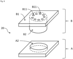
En référence à la
Selon cette première forme de réalisation, ledit système d'étanchéité 20 comprend deux éléments distincts. Le système d'étanchéité comprend un socle A et un bouchon B.According to this first embodiment, said sealing
Le socle A se présente comme une pièce rigide et peu souple, par exemple en plastique, de forme géométrique adaptée pour être insérée de façon ajustée dans le fond du premier logement 12A du palier 12. Selon l'exemple présenté en référence à la
Toujours en référence à la
Le deuxième plateau B1 comprend au moins un trou B11 traversant, comme représenté à la
Le deuxième plateau B1 peut comprendre plusieurs trous B11. Selon le mode de réalisation présenté, le nombre de trous B11 est égal au nombre de fils électriques 13. Les trous B11 du bouchon B ont une section transversale inférieure à la section transversale de chaque fil électrique 13 traversant le système d'étanchéité 20. Notamment, le diamètre de chaque trou B11 est inférieur au diamètre de chaque fil électrique 13. De cette façon, lorsqu'un fil électrique 13 est inséré dans un trou B11, aucun liquide ne peut ruisseler par capillarité le long de ce fil électrique 13 à travers ce trou B11. Une partie de l'étanchéité de la cavité 11 est donc assurée à la jonction entre chaque fil électrique 13 et chaque trou B11 associé audit fil électrique 13.The second tray B1 may include several holes B11. According to the embodiment presented, the number of holes B11 is equal to the number of
Le bouchon B comprend également une partie en saillie B2, dont la forme est adaptée pour que la partie en saillie B2 soit montée en force dans l'espace vide formé à l'intérieur de l'orifice A2 du socle A. Pour assurer cette montée en force, les dimensions de la partie en saillie B2 sont égales ou supérieures à celles de l'orifice A2. Ainsi, la partie en saillie B2 du bouchon B s'insère, à la manière d'un bouchon, dans l'orifice A2. Après insertion de la partie en saillie B2 dans l'orifice A2, une face du deuxième plateau B1 du bouchon B vient contre une face du premier plateau A1 du socle A. Ainsi, le socle A permet la compression du deuxième plateau B1 du bouchon B grâce au couvercle 16 ; une fois le bouchon B inséré dans le socle A, la partie en saillie B2 du bouchon est ainsi comprimée dans l'orifice A2 du socle A.The cap B also comprises a protruding part B2, the shape of which is adapted so that the protruding part B2 is mounted by force in the empty space formed inside the orifice A2 of the base A. in force, the dimensions of the projecting part B2 are equal to or greater than those of the orifice A2. Thus, the projecting part B2 of the plug B is inserted, like a plug, into the orifice A2. After insertion of the protruding part B2 in the orifice A2, one face of the second plate B1 of the cap B comes against a face of the first plate A1 of the base A. Thus, the base A allows the compression of the second tray B1 of cap B thanks to cover 16; once plug B has been inserted into base A, the protruding part B2 of the plug is thus compressed in the orifice A2 of base A.
En référence à la
Le couvercle 16 comprend également une ouverture 16-1 traversante, dont les bords sont configurés pour venir en appui sur le deuxième plateau B1 du bouchon B, notamment à la périphérie du deuxième plateau B1, et ainsi assurer l'étanchéité au niveau de l'ouverture 16-1. Une portion dudit couvercle 16 vient ainsi en appui sur ledit plateau B1 du bouchon B contre une ligne fermée décrivant la périphérie dudit plateau B1 du bouchon B.The
Le bouchon B étant constitué d'un matériau plus souple que le socle A, l'appui du couvercle 16 sur le deuxième plateau B1 du bouchon B assure une mise en compression du deuxième plateau B1 du bouchon B entre les bords de l'ouverture 16-1 et le premier plateau A1 du socle A, et par conséquent une étanchéité au niveau du passage du fil électrique 13. Contrairement à l'art antérieur, le contact entre le couvercle 16 et le palier 12 est uniforme, ce qui améliore l'étanchéité.The cap B being made of a more flexible material than the base A, the support of the
En référence à la
Dans une première étape d'un procédé d'étanchéification selon l'invention, la partie en saillie B2 du bouchon B est insérée dans l'orifice A2 du socle A. Ainsi, le bouchon B et le socle A constituent un ensemble dont les parties sont solidaires l'une de l'autre.In a first step of a sealing method according to the invention, the projecting part B2 of the cap B is inserted into the orifice A2 of the base A. Thus, the cap B and the base A constitute an assembly whose parts are integral to each other.
Dans une deuxième étape, chaque fil électrique 13 est inséré dans un trou B11 traversant le bouchon B. La première et la deuxième étape pouvant être inversées.In a second step, each
Enfin, dans une troisième étape, l'ensemble formé par le bouchon B, le socle A et le ou les fils électriques 13, est inséré dans le premier logement 12A du palier 12, de sorte que le socle A soit inséré au fond dudit premier logement 12A et de sorte que le ou les fils électriques 13 accèdent à l'intérieur de l'équipement électrique 10, notamment au deuxième logement 12B en passant par l'encoche 122 du palier 12. L'assemblage entre ces différents éléments est donc simple et rapide.Finally, in a third step, the assembly formed by the plug B, the base A and the electric wire(s) 13, is inserted into the
Enfin, dans une quatrième étape, le couvercle 16 est fixé par-dessus cet ensemble et la compression du deuxième plateau B1, placé entre le couvercle 16 et le socle A, permet d'étanchéifier l'équipement électrique 10 au niveau de la connexion électrique de l'équipement électrique 10.Finally, in a fourth step, the
Cet assemblage permet en outre d'assurer une double étanchéité au niveau de la connexion électrique de l'équipement électrique 10. Tout d'abord, l'insertion de chaque fil électrique 13 dans un trou B11 permet d'assurer l'étanchéité des fils électriques 13. D'autre part, l'étanchéité est aussi assurée par la compression des bords de l'ouverture 16-1 du couvercle 16 sur la partie externe du deuxième plateau B1 du bouchon B contre le socle A, lui-même inséré dans le premier logement 12A.This assembly also makes it possible to ensure a double seal at the level of the electrical connection of the
Ainsi, la présente invention permet un découplage entre l'étanchéité du passage des fils électriques 13 à travers le bouchon B et celle de l'équipement électrique 10.Thus, the present invention allows a decoupling between the tightness of the passage of the
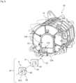
En référence à la
En référence à la
Claims (12)
- Sealing system (20) configured to allow the realization of a sealed electrical connection on a face of an item of electrical equipment (10), said sealing system (20) comprising:a base (A) comprising a first plate (A1), said first plate (A1) comprising a through-orifice (A2), the entire edge of the through-orifice (A2) being continuously comprised in a face of said first plate (A1),a stopper (B) comprising a second plate (B1) and a protruding part (B2) protruding from said plate (B1) of the stopper (B), said protruding part (B2) being designed to be inserted in the orifice (A2) of the base (A), a face of the second plate (B1) of the stopper (B) coming into contact with a face of the first plate (A1) of the base (A), the second plate (B1) and the protruding part (B2) comprising at least one through-hole (B11) which is intended to allow at least one electrical wire (13) to pass through, the at least one hole (B11) having a cross section smaller than that of the at least one electrical wire (13),said stopper (B) having a greater flexibility than the flexibility of the base (A), such that, when the sealing system (20) is positioned on a face of the item of electrical equipment (10) and when the plate of the stopper (B) butts against the plate of the base (A), the difference in flexibility allows the second plate (B1) of the stopper (B) to be stressed against the first plate (A1) of the base (A), so as to ensure a compression of the second plate (B1) of the stopper (B) contributing to the sealing of the item of electrical equipment (10), said protruding part (B2) of the stopper (B) being configured to be force-fitted in the orifice (A2) of the base (A) and the dimensions of the protruding part (B2) being equal to or greater than those of the orifice (A2),the sealing system (20) being configured to be inserted in a first cutout (12A) of corresponding dimensions provided in the face of the item of electrical equipment (10), such that a cover (16) of the item of electrical equipment (10) ensures that the second plate (B1) of the stopper (B) butts against the first plate (A1) of the base (A).
- Sealing system (20) according to Claim 1, wherein said base (A) and said stopper (B) are independent components.
- Sealing system (20) according to either of the preceding claims, wherein the base (A) and the stopper (B) form an independent assembly configured to be attached to a frame of the item of electrical equipment (10).
- Item of electrical equipment (10) comprising a sealing system according to one of the preceding claims, and also a cover (16) attached to said face of the item of electrical equipment (10) so as to at least partially close said item of electrical equipment (10), a portion of said cover (16) serving for abutment against said second plate (B1) of the stopper (B), at least against a closed line describing the periphery of said second plate (B1) of the stopper (B).
- Item of electrical equipment (10) according to the preceding claim, wherein said cover (16) comprises a through-opening (16-1), the edges of which come into continuous contact at least with said closed line describing the periphery of said second plate (B1) of the stopper (B), so as to surround said at least one hole (B11) of the second plate (B1) of the stopper (B).
- Item of electrical equipment (10) according to either one of Claims 4 and 5, comprising a bearing (12) forming a frame part of said item of electrical equipment (10), said bearing (12) having a first cutout (12A) containing said sealing system (20).
- Item of electrical equipment according to the preceding claim, wherein the base (A) is a component separate from the bearing (12) and is attached in the first cutout (12A).
- Item of electrical equipment according to the preceding claim, wherein a peripheral wall of said first cutout (12A) has a slot (122) extending from an opening in the first cutout (12A), the stopper (B) being received in said first cutout (12A) through said opening, said slot (122) being configured to allow the at least one electrical wire (13) to pass through towards the interior of the item of electrical equipment (10) when the stopper (B) is fitted in said first cutout (12A).
- Item of electrical equipment (10) according to Claim 6, comprising a sealing system (20) according to either of Claims 1 and 2, wherein the base (A) is secured to the bearing (12) or is formed in one piece with the bearing (12).
- Item of electrical equipment (10) according to the preceding claim, wherein the base (A) is comprised in a bottom of the first cutout (12A) receiving the stopper (B).
- Item of electrical equipment (10) according to Claim 6, comprising a sealing system (20) according to Claim 3.
- Method for sealing an item of electrical equipment (10) according to one of Claims 6 to 11, said method being intended to seal a cavity (11) provided in a bearing (12) forming a frame part of said item of electrical equipment (10), the method comprising the following steps:inserting the protruding part (B2) of the stopper (B) in the orifice (A2) of the base (A),inserting each cable (13) of the bundle of cables (13) in a hole (B11) of the stopper (B),inserting the assembly comprising the stopper (B), the base (A) and the bundle of cables (13) in the first cutout (12A) of the bearing (12),fastening the cover (16) to the bearing (12) such that the edges of the through-opening (16-1) of the cover (16) butt against the second plate (B1) of the stopper (B).
Applications Claiming Priority (1)
| Application Number | Priority Date | Filing Date | Title |
|---|---|---|---|
| FR1872974A FR3090221B1 (en) | 2018-12-14 | 2018-12-14 | Sealing system for electrical equipment |
Publications (2)
| Publication Number | Publication Date |
|---|---|
| EP3668286A1 EP3668286A1 (en) | 2020-06-17 |
| EP3668286B1 true EP3668286B1 (en) | 2023-05-10 |
Family
ID=66676668
Family Applications (1)
| Application Number | Title | Priority Date | Filing Date |
|---|---|---|---|
| EP19209553.7A Active EP3668286B1 (en) | 2018-12-14 | 2019-11-15 | Sealing system for electrical equipment |
Country Status (4)
| Country | Link |
|---|---|
| US (1) | US11128085B2 (en) |
| EP (1) | EP3668286B1 (en) |
| CN (1) | CN111328234B (en) |
| FR (1) | FR3090221B1 (en) |
Families Citing this family (2)
| Publication number | Priority date | Publication date | Assignee | Title |
|---|---|---|---|---|
| TWI651034B (en) * | 2018-06-01 | 2019-02-11 | 和碩聯合科技股份有限公司 | Waterproof structure |
| CN113531220A (en) * | 2020-04-15 | 2021-10-22 | 康普技术有限责任公司 | Cable sealing device and cable sealing system |
Citations (1)
| Publication number | Priority date | Publication date | Assignee | Title |
|---|---|---|---|---|
| EP2856568B1 (en) * | 2012-05-31 | 2018-07-11 | Delphi International Operations Luxembourg S.à r.l. | Single wire seal for sealing an electric cable in an aperture of a terminal |
Family Cites Families (14)
| Publication number | Priority date | Publication date | Assignee | Title |
|---|---|---|---|---|
| CA481856A (en) * | 1952-03-18 | Donald Clothier George | Closure members for devices for sealing the ends of electric cables | |
| JPH08315903A (en) * | 1995-05-19 | 1996-11-29 | Toyota Motor Corp | Seal member and seal structure |
| JPH08335420A (en) * | 1995-06-07 | 1996-12-17 | Sumitomo Wiring Syst Ltd | Grommet installation structure |
| JP4176854B2 (en) * | 1997-10-14 | 2008-11-05 | 藤倉ゴム工業株式会社 | Water stop device |
| JP4075718B2 (en) * | 2003-07-28 | 2008-04-16 | 三菱自動車工業株式会社 | Seal structure |
| DE10334518A1 (en) * | 2003-07-29 | 2005-02-17 | Harting Electric Gmbh & Co. Kg | Cable seal for a connector |
| JP2008028267A (en) * | 2006-07-24 | 2008-02-07 | Fanuc Ltd | Sealing structure of electric circuit unit |
| CN101154798B (en) * | 2006-09-30 | 2012-03-21 | 拉普工程公司 | Cable feed-through device and cable feed-through system |
| JP5314540B2 (en) * | 2009-09-01 | 2013-10-16 | 矢崎総業株式会社 | connector |
| JP2012075253A (en) * | 2010-09-29 | 2012-04-12 | Hitachi Industrial Equipment Systems Co Ltd | Waterproof device and waterproof method for electric wire, control device, and construction machinery |
| JP2013201053A (en) * | 2012-03-26 | 2013-10-03 | Hitachi Cable Ltd | Seal member and connector |
| JP5880804B1 (en) * | 2014-07-22 | 2016-03-09 | Nok株式会社 | Grommet |
| CN106207597B (en) * | 2016-07-29 | 2019-03-01 | 中航光电科技股份有限公司 | A kind of conducting wire via hole outlet structure |
| CN206992854U (en) * | 2017-03-16 | 2018-02-09 | 苏州双航机电有限公司 | A kind of waterproof construction of motor |
-
2018
- 2018-12-14 FR FR1872974A patent/FR3090221B1/en active Active
-
2019
- 2019-11-15 EP EP19209553.7A patent/EP3668286B1/en active Active
- 2019-12-10 CN CN201911259651.1A patent/CN111328234B/en active Active
- 2019-12-13 US US16/713,294 patent/US11128085B2/en active Active
Patent Citations (1)
| Publication number | Priority date | Publication date | Assignee | Title |
|---|---|---|---|---|
| EP2856568B1 (en) * | 2012-05-31 | 2018-07-11 | Delphi International Operations Luxembourg S.à r.l. | Single wire seal for sealing an electric cable in an aperture of a terminal |
Also Published As
| Publication number | Publication date |
|---|---|
| FR3090221B1 (en) | 2022-03-25 |
| US11128085B2 (en) | 2021-09-21 |
| US20200194927A1 (en) | 2020-06-18 |
| CN111328234A (en) | 2020-06-23 |
| EP3668286A1 (en) | 2020-06-17 |
| CN111328234B (en) | 2023-07-25 |
| FR3090221A1 (en) | 2020-06-19 |
Similar Documents
| Publication | Publication Date | Title |
|---|---|---|
| EP3668286B1 (en) | Sealing system for electrical equipment | |
| FR2935449A1 (en) | TEMPERATURE SENSOR MOUNTING UNIT | |
| FR2924277A1 (en) | SHIELD CONNECTOR AGAINST ELECTROMAGNETIC WAVES | |
| FR3050078B1 (en) | PYROTECHNIC CONNECTOR | |
| EP2086081B1 (en) | Electricity insulating disc for supporting a linear conductor and electric system comprising such a disc | |
| FR2837921A1 (en) | PRESSURE SENSOR AND MANUFACTURING METHOD THEREOF | |
| EP3499193A1 (en) | Device for measuring a physical parameter of a fluid of a motor vehicle circuit | |
| FR3081264A1 (en) | CABLE TIGHTENING DEVICE FOR SEALED ELECTRICAL CONNECTOR AND ELECTRICAL CONNECTOR | |
| FR2711393A1 (en) | System comprising a temperature tapping, especially on a plastic pipe | |
| EP1489713A1 (en) | Sealed lead-through device | |
| EP1251616B1 (en) | Sealing for electrical cable | |
| EP2546614A1 (en) | Detector or sensor device with an improved cable guide plug | |
| WO2013021119A2 (en) | Electrical connection device, assembly including such a device and an electronic board, and method for electrically connecting an electronic board | |
| EP0562970B1 (en) | Assembly of a toroidal core with coil | |
| FR2634618A1 (en) | DEVICE FORMING A VENT OF AERATION FOR ELECTRICAL OR ELECTRONIC PROTECTION HOUSING | |
| EP2690734B1 (en) | Seal for a cable run | |
| EP1531255B1 (en) | Sealing arrangement for an injector housing | |
| FR2707002A1 (en) | Improved screened electrical sensor | |
| FR3076609A1 (en) | Angular sensor | |
| EP1649472B1 (en) | Electromagnetic valve, method for attaching a solenoid to said electromagnetic valve, and method for detaching the solenoid from this electromagnetic valve | |
| FR2936201A1 (en) | Gear motor for windscreen wiper device of motor vehicle, has balancing membrane provided on case of interface, and through hole formed in and/or on connection element to allow exchange of air between inner volume of box and surrounding area | |
| EP3578849B1 (en) | Active hydraulic anti-vibration device and vehicle comprising such an active hydraulic anti-vibration device | |
| FR3045718A1 (en) | DEVICE FOR THE SEALED CROSSING OF A TURBOMACHINE FENCE | |
| FR3131114A1 (en) | Connector with improved seal, seal assembly and method of mounting a cable with this seal assembly | |
| EP2272135B1 (en) | Device for preventing the establishment of an electric arc between two conductive elements |
Legal Events
| Date | Code | Title | Description |
|---|---|---|---|
| PUAI | Public reference made under article 153(3) epc to a published international application that has entered the european phase |
Free format text: ORIGINAL CODE: 0009012 |
|
| STAA | Information on the status of an ep patent application or granted ep patent |
Free format text: STATUS: THE APPLICATION HAS BEEN PUBLISHED |
|
| AK | Designated contracting states |
Kind code of ref document: A1 Designated state(s): AL AT BE BG CH CY CZ DE DK EE ES FI FR GB GR HR HU IE IS IT LI LT LU LV MC MK MT NL NO PL PT RO RS SE SI SK SM TR |
|
| AX | Request for extension of the european patent |
Extension state: BA ME |
|
| STAA | Information on the status of an ep patent application or granted ep patent |
Free format text: STATUS: REQUEST FOR EXAMINATION WAS MADE |
|
| 17P | Request for examination filed |
Effective date: 20200924 |
|
| RBV | Designated contracting states (corrected) |
Designated state(s): AL AT BE BG CH CY CZ DE DK EE ES FI FR GB GR HR HU IE IS IT LI LT LU LV MC MK MT NL NO PL PT RO RS SE SI SK SM TR |
|
| STAA | Information on the status of an ep patent application or granted ep patent |
Free format text: STATUS: EXAMINATION IS IN PROGRESS |
|
| 17Q | First examination report despatched |
Effective date: 20220107 |
|
| RAP3 | Party data changed (applicant data changed or rights of an application transferred) |
Owner name: VALEO EAUTOMOTIVE GERMANY GMBH |
|
| GRAP | Despatch of communication of intention to grant a patent |
Free format text: ORIGINAL CODE: EPIDOSNIGR1 |
|
| STAA | Information on the status of an ep patent application or granted ep patent |
Free format text: STATUS: GRANT OF PATENT IS INTENDED |
|
| INTG | Intention to grant announced |
Effective date: 20221209 |
|
| GRAS | Grant fee paid |
Free format text: ORIGINAL CODE: EPIDOSNIGR3 |
|
| GRAA | (expected) grant |
Free format text: ORIGINAL CODE: 0009210 |
|
| STAA | Information on the status of an ep patent application or granted ep patent |
Free format text: STATUS: THE PATENT HAS BEEN GRANTED |
|
| RBV | Designated contracting states (corrected) |
Designated state(s): AL AT BE BG CH CY CZ DE DK EE ES FI GB GR HR HU IE IS IT LI LT LU LV MC MK MT NL NO PL PT RO RS SE SI SK SM TR |
|
| AK | Designated contracting states |
Kind code of ref document: B1 Designated state(s): AL AT BE BG CH CY CZ DE DK EE ES FI GB GR HR HU IE IS IT LI LT LU LV MC MK MT NL NO PL PT RO RS SE SI SK SM TR |
|
| REG | Reference to a national code |
Ref country code: GB Ref legal event code: FG4D Free format text: NOT ENGLISH |
|
| REG | Reference to a national code |
Ref country code: AT Ref legal event code: REF Ref document number: 1568055 Country of ref document: AT Kind code of ref document: T Effective date: 20230515 Ref country code: CH Ref legal event code: EP |
|
| REG | Reference to a national code |
Ref country code: DE Ref legal event code: R096 Ref document number: 602019028670 Country of ref document: DE |
|
| REG | Reference to a national code |
Ref country code: IE Ref legal event code: FG4D Free format text: LANGUAGE OF EP DOCUMENT: FRENCH |
|
| P01 | Opt-out of the competence of the unified patent court (upc) registered |
Effective date: 20230528 |
|
| REG | Reference to a national code |
Ref country code: LT Ref legal event code: MG9D |
|
| REG | Reference to a national code |
Ref country code: NL Ref legal event code: MP Effective date: 20230510 |
|
| REG | Reference to a national code |
Ref country code: AT Ref legal event code: MK05 Ref document number: 1568055 Country of ref document: AT Kind code of ref document: T Effective date: 20230510 |
|
| PG25 | Lapsed in a contracting state [announced via postgrant information from national office to epo] |
Ref country code: SE Free format text: LAPSE BECAUSE OF FAILURE TO SUBMIT A TRANSLATION OF THE DESCRIPTION OR TO PAY THE FEE WITHIN THE PRESCRIBED TIME-LIMIT Effective date: 20230510 Ref country code: PT Free format text: LAPSE BECAUSE OF FAILURE TO SUBMIT A TRANSLATION OF THE DESCRIPTION OR TO PAY THE FEE WITHIN THE PRESCRIBED TIME-LIMIT Effective date: 20230911 Ref country code: NO Free format text: LAPSE BECAUSE OF FAILURE TO SUBMIT A TRANSLATION OF THE DESCRIPTION OR TO PAY THE FEE WITHIN THE PRESCRIBED TIME-LIMIT Effective date: 20230810 Ref country code: NL Free format text: LAPSE BECAUSE OF FAILURE TO SUBMIT A TRANSLATION OF THE DESCRIPTION OR TO PAY THE FEE WITHIN THE PRESCRIBED TIME-LIMIT Effective date: 20230510 Ref country code: ES Free format text: LAPSE BECAUSE OF FAILURE TO SUBMIT A TRANSLATION OF THE DESCRIPTION OR TO PAY THE FEE WITHIN THE PRESCRIBED TIME-LIMIT Effective date: 20230510 Ref country code: AT Free format text: LAPSE BECAUSE OF FAILURE TO SUBMIT A TRANSLATION OF THE DESCRIPTION OR TO PAY THE FEE WITHIN THE PRESCRIBED TIME-LIMIT Effective date: 20230510 |
|
| PG25 | Lapsed in a contracting state [announced via postgrant information from national office to epo] |
Ref country code: RS Free format text: LAPSE BECAUSE OF FAILURE TO SUBMIT A TRANSLATION OF THE DESCRIPTION OR TO PAY THE FEE WITHIN THE PRESCRIBED TIME-LIMIT Effective date: 20230510 Ref country code: PL Free format text: LAPSE BECAUSE OF FAILURE TO SUBMIT A TRANSLATION OF THE DESCRIPTION OR TO PAY THE FEE WITHIN THE PRESCRIBED TIME-LIMIT Effective date: 20230510 Ref country code: LV Free format text: LAPSE BECAUSE OF FAILURE TO SUBMIT A TRANSLATION OF THE DESCRIPTION OR TO PAY THE FEE WITHIN THE PRESCRIBED TIME-LIMIT Effective date: 20230510 Ref country code: LT Free format text: LAPSE BECAUSE OF FAILURE TO SUBMIT A TRANSLATION OF THE DESCRIPTION OR TO PAY THE FEE WITHIN THE PRESCRIBED TIME-LIMIT Effective date: 20230510 Ref country code: IS Free format text: LAPSE BECAUSE OF FAILURE TO SUBMIT A TRANSLATION OF THE DESCRIPTION OR TO PAY THE FEE WITHIN THE PRESCRIBED TIME-LIMIT Effective date: 20230910 Ref country code: HR Free format text: LAPSE BECAUSE OF FAILURE TO SUBMIT A TRANSLATION OF THE DESCRIPTION OR TO PAY THE FEE WITHIN THE PRESCRIBED TIME-LIMIT Effective date: 20230510 Ref country code: GR Free format text: LAPSE BECAUSE OF FAILURE TO SUBMIT A TRANSLATION OF THE DESCRIPTION OR TO PAY THE FEE WITHIN THE PRESCRIBED TIME-LIMIT Effective date: 20230811 |
|
| PG25 | Lapsed in a contracting state [announced via postgrant information from national office to epo] |
Ref country code: FI Free format text: LAPSE BECAUSE OF FAILURE TO SUBMIT A TRANSLATION OF THE DESCRIPTION OR TO PAY THE FEE WITHIN THE PRESCRIBED TIME-LIMIT Effective date: 20230510 |
|
| PG25 | Lapsed in a contracting state [announced via postgrant information from national office to epo] |
Ref country code: SK Free format text: LAPSE BECAUSE OF FAILURE TO SUBMIT A TRANSLATION OF THE DESCRIPTION OR TO PAY THE FEE WITHIN THE PRESCRIBED TIME-LIMIT Effective date: 20230510 |
|
| PG25 | Lapsed in a contracting state [announced via postgrant information from national office to epo] |
Ref country code: SM Free format text: LAPSE BECAUSE OF FAILURE TO SUBMIT A TRANSLATION OF THE DESCRIPTION OR TO PAY THE FEE WITHIN THE PRESCRIBED TIME-LIMIT Effective date: 20230510 Ref country code: SK Free format text: LAPSE BECAUSE OF FAILURE TO SUBMIT A TRANSLATION OF THE DESCRIPTION OR TO PAY THE FEE WITHIN THE PRESCRIBED TIME-LIMIT Effective date: 20230510 Ref country code: RO Free format text: LAPSE BECAUSE OF FAILURE TO SUBMIT A TRANSLATION OF THE DESCRIPTION OR TO PAY THE FEE WITHIN THE PRESCRIBED TIME-LIMIT Effective date: 20230510 Ref country code: EE Free format text: LAPSE BECAUSE OF FAILURE TO SUBMIT A TRANSLATION OF THE DESCRIPTION OR TO PAY THE FEE WITHIN THE PRESCRIBED TIME-LIMIT Effective date: 20230510 Ref country code: DK Free format text: LAPSE BECAUSE OF FAILURE TO SUBMIT A TRANSLATION OF THE DESCRIPTION OR TO PAY THE FEE WITHIN THE PRESCRIBED TIME-LIMIT Effective date: 20230510 Ref country code: CZ Free format text: LAPSE BECAUSE OF FAILURE TO SUBMIT A TRANSLATION OF THE DESCRIPTION OR TO PAY THE FEE WITHIN THE PRESCRIBED TIME-LIMIT Effective date: 20230510 |
|
| PGFP | Annual fee paid to national office [announced via postgrant information from national office to epo] |
Ref country code: DE Payment date: 20231107 Year of fee payment: 5 |
|
| REG | Reference to a national code |
Ref country code: DE Ref legal event code: R097 Ref document number: 602019028670 Country of ref document: DE |
|
| PLBE | No opposition filed within time limit |
Free format text: ORIGINAL CODE: 0009261 |
|
| STAA | Information on the status of an ep patent application or granted ep patent |
Free format text: STATUS: NO OPPOSITION FILED WITHIN TIME LIMIT |
|
| 26N | No opposition filed |
Effective date: 20240213 |
|
| PG25 | Lapsed in a contracting state [announced via postgrant information from national office to epo] |
Ref country code: SI Free format text: LAPSE BECAUSE OF FAILURE TO SUBMIT A TRANSLATION OF THE DESCRIPTION OR TO PAY THE FEE WITHIN THE PRESCRIBED TIME-LIMIT Effective date: 20230510 |