EP3668090B1 - Projektionsvorrichtung und betriebsverfahren dafür - Google Patents
Projektionsvorrichtung und betriebsverfahren dafür Download PDFInfo
- Publication number
- EP3668090B1 EP3668090B1 EP19210804.1A EP19210804A EP3668090B1 EP 3668090 B1 EP3668090 B1 EP 3668090B1 EP 19210804 A EP19210804 A EP 19210804A EP 3668090 B1 EP3668090 B1 EP 3668090B1
- Authority
- EP
- European Patent Office
- Prior art keywords
- light
- switch
- ratio
- mode
- video frame
- Prior art date
- Legal status (The legal status is an assumption and is not a legal conclusion. Google has not performed a legal analysis and makes no representation as to the accuracy of the status listed.)
- Active
Links
Images


Classifications
-
- H—ELECTRICITY
- H04—ELECTRIC COMMUNICATION TECHNIQUE
- H04N—PICTORIAL COMMUNICATION, e.g. TELEVISION
- H04N9/00—Details of colour television systems
- H04N9/12—Picture reproducers
- H04N9/31—Projection devices for colour picture display, e.g. using electronic spatial light modulators [ESLM]
- H04N9/3179—Video signal processing therefor
- H04N9/3182—Colour adjustment, e.g. white balance, shading or gamut
-
- H—ELECTRICITY
- H04—ELECTRIC COMMUNICATION TECHNIQUE
- H04N—PICTORIAL COMMUNICATION, e.g. TELEVISION
- H04N9/00—Details of colour television systems
- H04N9/12—Picture reproducers
- H04N9/31—Projection devices for colour picture display, e.g. using electronic spatial light modulators [ESLM]
- H04N9/3141—Constructional details thereof
- H04N9/315—Modulator illumination systems
- H04N9/3155—Modulator illumination systems for controlling the light source
-
- G—PHYSICS
- G03—PHOTOGRAPHY; CINEMATOGRAPHY; ANALOGOUS TECHNIQUES USING WAVES OTHER THAN OPTICAL WAVES; ELECTROGRAPHY; HOLOGRAPHY
- G03B—APPARATUS OR ARRANGEMENTS FOR TAKING PHOTOGRAPHS OR FOR PROJECTING OR VIEWING THEM; APPARATUS OR ARRANGEMENTS EMPLOYING ANALOGOUS TECHNIQUES USING WAVES OTHER THAN OPTICAL WAVES; ACCESSORIES THEREFOR
- G03B21/00—Projectors or projection-type viewers; Accessories therefor
- G03B21/14—Details
- G03B21/20—Lamp housings
- G03B21/2053—Intensity control of illuminating light
-
- G—PHYSICS
- G06—COMPUTING OR CALCULATING; COUNTING
- G06T—IMAGE DATA PROCESSING OR GENERATION, IN GENERAL
- G06T7/00—Image analysis
- G06T7/90—Determination of colour characteristics
-
- H—ELECTRICITY
- H04—ELECTRIC COMMUNICATION TECHNIQUE
- H04N—PICTORIAL COMMUNICATION, e.g. TELEVISION
- H04N21/00—Selective content distribution, e.g. interactive television or video on demand [VOD]
- H04N21/40—Client devices specifically adapted for the reception of or interaction with content, e.g. set-top-box [STB]; Operations thereof
- H04N21/41—Structure of client; Structure of client peripherals
- H04N21/422—Input-only peripherals, i.e. input devices connected to specially adapted client devices, e.g. global positioning system [GPS]
- H04N21/42204—User interfaces specially adapted for controlling a client device through a remote control device; Remote control devices therefor
-
- H—ELECTRICITY
- H04—ELECTRIC COMMUNICATION TECHNIQUE
- H04N—PICTORIAL COMMUNICATION, e.g. TELEVISION
- H04N5/00—Details of television systems
- H04N5/44—Receiver circuitry for the reception of television signals according to analogue transmission standards
- H04N5/57—Control of contrast or brightness
-
- H—ELECTRICITY
- H04—ELECTRIC COMMUNICATION TECHNIQUE
- H04N—PICTORIAL COMMUNICATION, e.g. TELEVISION
- H04N9/00—Details of colour television systems
- H04N9/12—Picture reproducers
- H04N9/31—Projection devices for colour picture display, e.g. using electronic spatial light modulators [ESLM]
- H04N9/3141—Constructional details thereof
- H04N9/315—Modulator illumination systems
- H04N9/3164—Modulator illumination systems using multiple light sources
-
- H—ELECTRICITY
- H05—ELECTRIC TECHNIQUES NOT OTHERWISE PROVIDED FOR
- H05B—ELECTRIC HEATING; ELECTRIC LIGHT SOURCES NOT OTHERWISE PROVIDED FOR; CIRCUIT ARRANGEMENTS FOR ELECTRIC LIGHT SOURCES, IN GENERAL
- H05B45/00—Circuit arrangements for operating light-emitting diodes [LED]
- H05B45/20—Controlling the colour of the light
-
- H—ELECTRICITY
- H05—ELECTRIC TECHNIQUES NOT OTHERWISE PROVIDED FOR
- H05B—ELECTRIC HEATING; ELECTRIC LIGHT SOURCES NOT OTHERWISE PROVIDED FOR; CIRCUIT ARRANGEMENTS FOR ELECTRIC LIGHT SOURCES, IN GENERAL
- H05B47/00—Circuit arrangements for operating light sources in general, i.e. where the type of light source is not relevant
- H05B47/10—Controlling the light source
- H05B47/165—Controlling the light source following a pre-assigned programmed sequence; Logic control [LC]
Definitions
- the invention relates to a light-emitting technology; more particularly, the invention relates to a projection apparatus and an operation method thereof.
- known projection lamps In known projection lamps, light-emitting devices simply emit projected beams with fixed brightness, and the known projection lamps are unable to adjust the brightness of the project beams according to different scenarios. For instance, since the brightness of the projected beams of the known projection lamps are fixed, it is unlikely to enhance the projection beam for certain object or in response to a certain scenario.
- WO 2018/025390 A1 relates to a technique for adjusting the light emission amounts of a plurality of independently controllable light sources more sophisticatedly in a projection video display device that uses the plurality of independently controllable light sources.
- a location step may include acquiring an image and locating a character region of the image.
- the character region may include a character and a local background.
- the method may further include a background judgment step for determining whether the local background is a complex background; a determination step for determining a color of the character if the local background is a complex background; a construction step for constructing a mask for the character by combining the color of the character and a character region; and a first recognition step for extracting the character from the character region by using the mask, recognizing the character, and outputting the recognition result.
- US 2003/179192 A1 relates to a display system that includes plural light sources, and a controller coupled with the light sources and configured to modify sequencing of the light sources to display an image based on display conditions.
- US 2012/182525 A1 relates to a light source device which includes a first light source that emits first polarized light of a plurality of colors including different wavelengths; a second light source that emits second polarized light whose polarization state differs from that of the first polarized light and that includes light of at least one color from among the plurality of colors; and a first color synthesis optical element that synthesizes the first polarized light emitted from the first light source and the second polarized light emitted from the second light source.
- US 2010/091050 A1 relates to a solid state light (SSL) based projection display system comprising a spatial light modulator (SLM) device having a plurality of digitally controllable pixels and illuminated by a plurality of SSL devices optically coupled to the SLM by illumination optics; projection optics optically coupled to the SLM device to magnify an image generated by the SLM device; a pulse width modulation (PWM) block coupled to the SLM device to control the reflective states of each of the pixels of an image forming surface of the SLM device; and a hierarchical multiplexing functional block coupled to receive digital image data and a multiplicity of other external inputs and to provide control and synchronization signals to the plurality of SSL devices and the PWM modulation functional block.
- SLM spatial light modulator
- PWM pulse width modulation
- the invention provides a projection apparatus and an operation method thereof to dynamically increase a brightness of a projected beam of a light-emitting device according to color content of a video frame.
- an embodiment of the invention provides a projection apparatus according to independent claim 1.
- the projection apparatus includes a light-emitting device, a driving circuit, and a control circuit.
- the driving circuit is coupled to the light-emitting device.
- the driving circuit is configured to drive the light-emitting device according to at least one control signal to generate a projected beam.
- the control circuit is configured to receive at least one video frame and to analyze color content of the at least one video frame.
- the control circuit is configured to select one of a highlight mode and a normal mode as a selected mode according to the color content and to correspondingly set at least one control signal to the driving circuit according to the selected mode.
- a brightness of the projected beam of the light-emitting device in the highlight mode is greater than that in the normal mode.
- a ratio of a number of red sub-pixels satisfying a condition that a gray scale of a red sub-pixel is greater than a red threshold in the at least one video frame to a number of all red sub-pixels in the at least one video frame is a first ratio.
- a ratio of a number of green sub-pixels satisfying a condition that a gray scale of a green sub-pixel is greater than a green threshold in the at least one video frame to a number of all green sub-pixels in the at least one video frame is a second ratio.
- a ratio of a number of blue sub-pixels satisfying a condition that a gray scale of a blue sub-pixel is greater than a blue threshold in the at least one video frame to a number of all blue sub-pixels in the at least one video frame is a third ratio.
- the control circuit selects the highlight mode as the selected mode.
- the control circuit selects the normal mode as the selected mode.
- an embodiment of the invention provides an operation method of a projection apparatus according to independent claim 14.
- the operation method includes driving a light-emitting device by a driving circuit according to at least one control signal to generate a projected beam; analyzing color content of at least one video frame by a control circuit; and selecting, by the control circuit, one of a highlight mode and a normal mode as a selected mode according to the color content, and correspondingly setting the at least one control signal to the driving circuit according to the selected mode.
- a brightness of the projected beam of the light-emitting device in the highlight mode is greater than a brightness of the projected beam of the light-emitting device in the normal mode.
- a ratio of a number of red sub-pixels satisfying a condition that a gray scale of a red sub-pixel is greater than a red threshold in the at least one video frame to a number of all red sub-pixels in the at least one video frame is a first ratio.
- a ratio of a number of green sub-pixels satisfying a condition that a gray scale of a green sub-pixel is greater than a green threshold in the at least one video frame to a number of all green sub-pixels in the at least one video frame is a second ratio.
- a ratio of a number of blue sub-pixels satisfying a condition that a gray scale of a blue sub-pixel is greater than a blue threshold in the at least one video frame to a number of all blue sub-pixels in the at least one video frame is a third ratio.
- the control circuit selects the highlight mode as the selected mode.
- the control circuit selects the normal mode as the selected mode
- the embodiments of the invention at least demonstrate one of the advantages or effects below.
- the color content of the video frame can be analyzed.
- the projection apparatus can switch the operation mode to one of the highlight mode and the normal mode.
- the projection apparatus is able to dynamically increase the brightness of the projected beam of the light-emitting device according to actual scenarios.
- FIG. 1 is a schematic circuit block view of a projection apparatus 100 according to an embodiment of the invention.
- the projection apparatus 100 may act as a projection lamp, a projector, and/or any other optical projection apparatus.
- the projection apparatus 100 includes a control circuit 110, at least one driving circuit 120, and at least one light-emitting device 130.
- the control circuit 110 controls the projection apparatus 100 to act as a projection lamp, a projector, and/or any other optical projection apparatus.
- the projection apparatus 100 includes a control circuit 110, at least one driving circuit 120, and at least one light-emitting device 130.
- other components e.g., a display panel, a keyboard panel, and so on
- the control circuit 110 can receive at least one video frame (or a video frame stream).
- the control circuit 110 can analyze color content of the video frame and select one of a highlight mode and a normal mode as a selected mode according to the color content of the video frame.
- the control circuit 110 correspondingly sets (assigns) at least one control signal Sc to the driving circuit 120 according to the selected mode.
- An input terminal of the driving circuit 120 is coupled to the control circuit 110 to receive the control signal Sc.
- An output terminal of the driving circuit 120 is coupled to the light-emitting device 130.
- the control circuit 110 correspondingly sets the control signal Sc according to the selected mode, and the driving circuit 120 can drive the light-emitting device 130 to generate a projected beam according to the control signal Sc.
- the projected beam generated by the light-emitting device 130 can be projected to the outside of the projection apparatus 100 through an optical element (or an optical element set, not shown).
- the optical element may include a light valve, a lens (or a lens assembly), a mirror, and/or other optical elements.
- the control circuit 110 correspondingly sets the control signal Sc according to the selected mode, and the driving circuit 120 can drive the light-emitting device 130 to generate a projected beam according to the control signal Sc.
- the control circuit 110 can adjust the brightness of the projected beam of the light-emitting device 130 according to the selected mode.
- a brightness of the projected beam of the light-emitting device 130 in the highlight mode is greater than the brightness of the projected beam of the light-emitting device 130 in the normal mode.
- the control circuit 110 can decrease the driving current of the light-emitting device 130, so as to reduce power consumption.
- control circuit 110 can increase the driving current of the light-emitting device 130 (e.g., by setting the driving current as a rated current/maximum current of the light-emitting device 130), so as to ensure that the output has a super brightness.
- FIG. 2 is a schematic block view of a control device according to an embodiment of the invention.
- a video frame (or a video frame stream) is input to a control circuit 110.
- the control circuit 110 can analyze color content of the video frame.
- the control circuit 110 can determine whether the video frame is a white image frame (e.g., an all-white image).
- the control circuit 110 selects a highlight mode as a selected mode (step S240) and sets a control signal Sc according to the highlight mode.
- the driving circuit 120 can adjust/set the driving current for driving the light-emitting device 130 in accordance with the control signal Sc.
- the driving current provided by the driver circuit 120 to the light-emitting device 130 may be fixed current (the driving current is not related to the application scenario or other application conditions).
- the driving current supplied to the light-emitting device 130 in the highlight mode is greater than the driving current supplied to the light-emitting device 130 in the normal mode.
- the control circuit 110 selects a normal mode as the selected mode (step S250) and correspondingly sets a control signal Sc according to the normal mode.
- the driving circuit 120 can dynamically adjust/variate the driving current of the light-emitting device 130 according to the application scenario or other application conditions.
- the driving current supplied to the light-emitting device 130 in the normal mode is smaller than the driving current supplied to the light-emitting device 130 in the highlight mode.
- the way to operate the control circuit 110 should not be limited to those provided in the embodiment depicted in FIG. 2 .
- an operation mode of the control circuit 110 can be switched from the normal mode to the highlight mode, and the control circuit 110 correspondingly sets the control signal Sc according to the highlight mode; when a non-white object shows up in the white image frame, or when the color content of the video frame indicates that the video frame is no longer the white image frame, the operation mode of the control circuit 110 is switched from the highlight mode to the normal mode, and the control circuit 110 correspondingly sets the control signal Sc according to the normal mode. For instance, if a mouse cursors moves into the white image frame, the operation mode of the control circuit 110 is instantly switched from the highlight mode to the normal mode.
- the control circuit 110 can determine the color content of the video frame (e.g., determine whether the white image occupies most of the video frame) according to a histogram of the video frame.
- FIG. 3 is a histogram of a video frame according to an embodiment of the invention. Please refer to FIG. 1 and FIG. 3 .
- the control circuit 110 can analyze red sub-pixels in the video frame and thus obtain the histogram R of the red sub-pixels, analyze green sub-pixels in the video frame and thus obtain the histogram G of the green sub-pixels, and analyze blue sub-pixels in the video frame and thus obtain the histogram B of the blue sub-pixels.
- the horizontal axis of the histogram represents the gray scale
- the vertical axis of the histogram represents the number of sub-pixels
- the histograms of different pixels are represented by different line forms
- the histogram R of the red sub-pixels is represented by a blank
- the histogram G of the green sub-pixels is represented by a dot matrix
- the histogram B of the blue sub-pixels is indicated by a diagonal line.
- a ratio of the number of the red sub-pixels satisfying the condition to the number of all red sub-pixels in the video frame is a first ratio; if a green sub-pixel satisfies a condition that a gray scale of the green sub-pixel is greater than a green threshold, a ratio of the number of the green sub-pixels satisfying the condition to the number of all green sub-pixels in the video frame is a second ratio; if a blue sub-pixel satisfies a condition that a gray scale of the blue sub-pixel is greater than a blue threshold, a ratio of the number of the blue sub-pixels satisfying the condition to the number of all blue sub-pixels in the video frame is a third ratio.
- the red threshold, the green threshold, and the blue threshold can be determined according to design requirements.
- the control circuit 110 selects the highlight mode as the selected mode and correspondingly sets the control signal Sc according to the highlight mode.
- the control circuit 110 selects the normal mode as the selected mode and correspondingly sets the control signal Sc according to the normal mode.
- the first ratio threshold, the second ratio threshold, and the third ratio threshold can be determined according to design requirements.
- the first ratio threshold, the second ratio threshold, and the third ratio threshold can be the same values or different values. For instance, if the first ratio is greater than 95%, the second ratio is greater than 95%, and the third ratio is greater than 95%, the control circuit 110 selects the highlight mode as the selected mode.
- the projection apparatus 100 further includes a user interface circuit 140.
- the user interface circuit 140 is able to provide a human-machine interface for receiving a user's command.
- the user interface circuit 140 can transmit the user's command to the control circuit 110.
- the control circuit 110 can select one of the highlight mode and the normal mode as the selected mode according to the user's command and further correspondingly set the control signal Sc according to the selected mode.
- the user interface circuit 140 may be omitted.
- FIG. 4 is a schematic view of a human-machine interface according to an embodiment of the invention.
- the user interface circuit 140 can provide the human-machine interface image shown in FIG. 4 , i.e., an on-screen display (OSD) menu.
- OSD on-screen display
- the user can select to enable a "normal projection illumination mode” and/or a "special display illumination mode”.
- an input mechanism e.g., buttons, a touch panel, a mouse cursor, and/or other input components
- the user can transmit the user's command to the user interface circuit 140.
- the user interface circuit 140 can transmit the user's command to the control circuit 110.
- control circuit 110 can select one of the highlight mode and the normal mode as the selected mode according to the user's command and further correspondingly set the control signal Sc according to the selected mode. For instance, when the "special display illumination mode" is enabled by the user (the set value is "On"), the control circuit 110 can perform the process depicted in FIG. 2 .
- the user interface circuit 140 can receive an Infrared (IR) signal.
- IR Infrared
- the user can transmit the user's command to the user interface circuit 140 through an IR remote control, so as to set the operation mode of the control circuit 110 as the highlight mode or the normal mode.
- a personal computer may be connected to the user interface circuit 140 through a RS-232 connection port (a computer serial port).
- the personal computer can transmit the user's command to the user interface circuit 140, so as to determine whether the operation mode of the control circuit 110 is set as the highlight mode or the normal mode.
- the light-emitting device 130 may include a laser light source, a light-emitting diode (LED), a light bulb, or any other light-emitting component.
- the light-emitting device 130 may include one or more light-emitting components.
- the number of the driving circuit 120 may be plural, so as to respectively drive the light-emitting components.
- the number of the driving circuit 120 may just be one.
- a color of the projected beam of the light-emitting device 130 can be determined according to design requirements.
- the light-emitting device 130 may include a white LED to emit a white projected beam.
- the light-emitting device 130 can include a red LED, a green LED, and a blue LED.
- the driving circuit 120 can drive the red LED, the green LED, and the blue LED of the light-emitting device 130 according to the control signal Sc to generate the projected beam.
- a light-emitting period of the blue LED and a light-emitting period of the red LED are not overlapped, and the light-emitting period of the blue LED and a light-emitting period of the green LED are not overlapped.
- the light-emitting device 130 applies the red LED, the green LED, and the blue LED to emit white projected beam or projected beams of other colors.
- the light-emitting period of the red LED, the light-emitting period of the green LED, and a light-emitting period of the blue LED are completely overlapped, so as to emit the white projected beam with great brightness.
- the light-emitting device 130 may include a white LED which is turned on in the highlight mode, such as a light-emitting period of the white LED, a light-emitting period of the red LED, a light-emitting period of the green LED, and a light-emitting period of the blue LED are completely overlapped in the highlight mode to generate the white projected beam.
- a white LED which is turned on in the highlight mode, such as a light-emitting period of the white LED, a light-emitting period of the red LED, a light-emitting period of the green LED, and a light-emitting period of the blue LED are completely overlapped in the highlight mode to generate the white projected beam.
- the control signal Sc includes a first switch signal associated with the red LED, a second switch signal associated with the green LED, and a third switch signal associated with the blue LED.
- the driving circuit 120 can respectively drive the red LED, the green LED, and the blue LED of the light-emitting device 130, so as to generate the projected beam.
- the first switch signal is at a first logic level
- the red LED emits light
- the first switch signal is at a second logic level
- the red LED does not emit light.
- a duty ratio of the first switch signal, a duty ratio of the second switch signal, and a duty ratio of the third switch signal are all 100%.
- the light-emitting device 130 can emit the white projected beam with great brightness.
- the duty ratio of at least one of the first switch signal, the second switch signal, and the third switch signal is less than 100%.
- the duty ratio of the first switch signal, the duty ratio of the second switch signal, and the duty ratio of the third switch signal may be a fixed value close to 100% in the highlight mode.
- the duty ratio of the first switch signal, the duty ratio of the second switch signal, and the duty ratio of the third switch signal may be a dynamic value away from 100% (e.g., a dynamic value between 0% and 50%, but the invention is not limited thereto) in a normal mode.
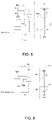
- FIG. 5 is a schematic diagram showing the activation periods (duty periods) of a red light emitting diode (LED), a green LED, and a blue LED in a highlight mode according to an embodiment of the invention.
- the horizontal axis shown in FIG. 5 represents time, and the vertical axis represents the state of the LED.
- “On” in FIG. 5 indicates that the LED is turn on, and “Off' indicates that the LED is turn off.
- the "activation period” means a period during which the state of the LED is continuously turned on (that is, a period during which the light is continuously emitted).
- the curve 501 shown in FIG. 5 indicates the state of the red LED
- the curve 502 indicates the state of the green LED
- the curve 503 indicates the state of the blue LED.
- the duty ratio of the red LED, the duty ratio of the green LED, and the duty ratio of the blue LED can be fixed values close to 100%, or even 100%. Therefore, in the embodiment shown in FIG. 5 , the activation period of the red LED, the activation period of the green LED, and the activation period of the blue LED completely overlap each other. That is, the overlapping ratio of the activation period of the curve 501 shown in FIG. 5 and the activation period of the curve 502 is 100%, and the overlapping ratio of the activation period of the curve 502 and the activation period of the curve 503 is also 100%. In an embodiment, the duty ratio of the red LED, the duty ratio of the green LED, and the duty ratio of the blue LED may be 100%.
- the "On" states of the curves 501 to 503 are completely interactively overlapped, that is, the overlapping ratio of between the three activation periods is 100%, so that the light-emitting device 130 can continuously emit positive-white projected light with high brightness.
- the user interface circuit 140 may transmit an overlay adjustment information (user instructions) to the control circuit 110 to set/adjust the overlapping ratio of the activation period of the red LED, the activation period of the green LED, and the activation period of the blue LED during the highlight mode.
- an overlay adjustment information user instructions
- FIG. 6 is a schematic diagram showing the activation periods of a red LED, a green LED, and a blue LED in a normal mode according to an embodiment of the invention.
- the horizontal axis shown in FIG. 6 represents time, and the vertical axis represents the state of the LED.
- "On” in FIG. 6 indicates that the LED is turned on, and "Off” indicates that the LED is turned off.
- the curve 601 shown in FIG. 6 indicates the state of the red LED, the curve 602 indicates the state of the green LED, and the curve 603 indicates the state of the blue LED.
- the duty ratios of the red, green, and blue LEDs may be dynamic values that are away from 100%, such as between 0% and 90%.
- the activation period of the red LED, the activation period of the green LED, and the activation period of the blue LED do not overlap each other at all. That is, the overlapping ratio of the activation period of the curve 601 (the red LED) shown in FIG. 6 and the activation period of the curve 602 (the green LED) is 0%, and the overlapping ratio of the activation period of the curve 602 (the green LED) and the activation period of the curve 603 (the blue LED) is also 0%.
- FIG. 7 is a schematic view showing the activation periods of a red LED, a green LED, and a blue LED in a normal mode according to another embodiment of the invention.
- the horizontal axis shown in FIG. 7 represents time, and the vertical axis represents the state of the LED.
- "On” in FIG. 7 indicates that the LED is turned on, and "Off' indicates that the LED is turned off.
- the curve 701 shown in FIG. 7 indicates the state of the red LED, the curve 702 indicates the state of the green LED, and the curve 703 indicates the state of the LED.
- the activation period of the red LED, the activation period of the green LED, and the activation period of the blue LED partially overlap each other.
- PW shown in FIG. 7 indicates an activation period of the LED (a period of "continuously turned on “)
- OL indicates an overlapping period in which the activation periods of the two LEDs partially overlap each other.
- the overlapping ratio of the overlapping period OL to the activation period PW may be an arbitrary value. For example, in the normal mode, the overlapping ratio of two of the activation period of the red LED, the activation period of the green LED, and the activation period of the blue LED is from 0 to 40%.
- the overlapping ratio (i.e., the ratio of OL to PW) of the activation period of the curve 701 (the red LED) shown in FIG. 7 and the activation period of the curve 702 (the green LED) may be 0 to 40%
- the overlapping ratio (i.e., the ratio of OL to PW) of the activation period of the curve 702 (the green LED) and the activation period of the curve 703 (the blue LED) may also be 0-40%.
- the driving current of the light-emitting device 130 may be a fixed large current.
- the driving current of the light-emitting device 130 may be a small current that is dynamically adjusted and fluctuates.
- the control circuit 110 can reduce the driving current of the light-emitting device 130 to save power consumption.
- the control circuit 110 can increase the driving current of the light-emitting device 130 to ensure that the output has a super brightness.
- the driving circuit 120 may include a first current source (not shown), a second current source (not shown), and a third current source (not shown), and the control signal Sc includes a first bias voltage, a second bias voltage, and a third bias voltage.
- the first bias voltage controls a first current source associated with the red LED of the light-emitting device 130
- the second bias voltage controls a second current source associated with the green LED of the light-emitting device 130
- the third bias voltage controls a third current source associated with the blue LED of the light-emitting device 130. For instance, when the current from the first current source is increased by changing the first bias voltage, the brightness of the projected beam of the red LED of the light-emitting device 130 can be increased.
- the first bias voltage is a first fixed voltage
- the second bias voltage is a second fixed voltage
- the third bias voltage is a third fixed voltage.
- the level of the first fixed voltage, the level of the second fixed voltage, and the level of the third fixed voltage can be determined according to design requirements.
- the level of the fixed voltage can be designed according to electrical conditions and the current source of the light-emitting device.
- the first bias voltage is a first dynamic voltage less than the first fixed voltage
- the second bias voltage is a second dynamic voltage less than the second fixed voltage
- the third bias voltage is a third dynamic voltage less than the third fixed voltage.
- the brightness of the projected beam of the light-emitting device 130 in the highlight mode is greater than the brightness of the projected beam of the light-emitting device 130 in the normal mode.
- FIG. 8 is a schematic circuit block view of the control circuit 110, the driving circuit 120, and the light-emitting device 130 depicted in FIG. 1 according to an embodiment of the invention.
- the driving circuit 120 shown in FIG. 8 includes a current source 121.
- the current source 121 correspondingly provides the driving current to the light-emitting device 130 according to a bias voltage Vbias to generate the projected beam.
- the light-emitting device 130 shown in FIG. 8 includes an LED 131.
- the LED 131 may be the white LED, the red LED, the green LED, or the blue LED mentioned in the previous embodiments.
- a first terminal (e.g., an anode) of the LED 131 is coupled to a current providing terminal of the current source 121, so as to receive the driving current.
- a second terminal (e.g., a cathode) of the LED 131 is coupled to a reference voltage VSSA (e.g., a ground voltage or any other fixed voltage).
- the way to operate the driving circuit 120 and the light-emitting device 130 should not be limited to those provided in the embodiment depicted in FIG. 8 .
- the first terminal (e.g., the cathode) of the LED 131 is coupled to a current obtaining terminal of the current source 121
- the second terminal (e.g., the anode) of the LED 131 is coupled to a power voltage VDDA.
- the current providing terminal of the current source 121 is coupled to the reference voltage VSSA.
- the terminals of the current source 121 are not limited to be coupled to the power voltage VDDA and the reference voltage VSSA and can be changed to be coupled to other bias points according to design requirements.
- the control circuit 110 includes a voltage generating circuit 111, a bias circuit 112, a switch 113, and a controller 114.
- the voltage generating circuit 111 is configured to generate a fixed voltage VI.
- the way to implement the voltage generating circuit 111 is not limited in the embodiment.
- the voltage generating circuit 111 may include a resistor R1 and a resistor R2.
- a first terminal of the resistor R1 is coupled to the power voltage VDDA.
- a second terminal of the resistor R1 is coupled to the first selection terminal of the switch 113, so as to provide the fixed voltage VI.
- a first terminal of the resistor R2 is coupled to the second terminal of the resistor R1.
- a second terminal of the resistor R2 is coupled to the reference voltage VSSA.
- the bias circuit 112 is configured to generate a dynamic voltage V2 less than the fixed voltage VI.
- the way to implement the bias circuit 112 is not limited in the embodiment.
- the bias circuit 112 may be a known bias circuit providing a bias voltage to a driving circuit of a light-emitting device in a known projector.
- the known bias circuit can generate the dynamic voltage V2 and provide the same to the light-emitting device driving circuit, so as to determine/adjust the current of the light-emitting device (i.e., determine/adjust the brightness of the light-emitting device).
- the implementation details of the known bias circuit are not explained hereinafter.
- the first selection terminal of the switch 113 is coupled to the voltage generating circuit 111 to receive the fixed voltage VI.
- the second selection terminal of the switch 113 is coupled to the bias circuit 112 to receive the dynamic voltage V2.
- the common terminal of the switch 113 is coupled to the current source 121 to provide the bias voltage Vbias.
- the controller 114 can analyze the color content of the video frame, so as to select one of the highlight mode and the normal mode as the selected mode. In the highlight mode, the controller 114 controls the switch 113 to transmit the fixed voltage VI to the current source 121 as the bias voltage Vbias, and the current source 121 correspondingly supplies a driving current to the light-emitting device 130 according to the bias voltage Vbias (i.e., the fixed voltage VI) to generate the projected light.
- Vbias i.e., the fixed voltage VI
- the controller 114 controls the switch 113 to transmit the dynamic voltage V2 to the current source 121 as the bias voltage Vbias, and the current source 121 correspondingly supplies a driving current to the light-emitting device 130 according to the bias voltage Vbias (i.e., the fixed voltage V2) to generate the projected light. Since the fixed voltage VI is greater than the dynamic voltage V2, the brightness of the projected beam of the LED 131 in the highlight mode is greater than the brightness of the projected beam of the LED 131 in the normal mode.
- FIG. 9 is a schematic circuit block view of the control circuit 110, the driving circuit 120, and the light-emitting device 130 depicted in FIG. 1 according to another embodiment of the invention.
- the driving circuit 120 shown in FIG. 9 includes a power switch 122.
- a first terminal of the power switch 122 is coupled to the power voltage VDDA.
- a second terminal of the power switch 122 is coupled to the light-emitting device 130.
- the power switch 122 determines whether to transmit the power voltage VDDA to the light-emitting device 130 according to a switch signal Vsw, so as to generate the projected beam.
- the related descriptions of the light-emitting device 130 depicted in FIG. 9 can be found in the descriptions of the light-emitting device 130 depicted in FIG. 8 and thus will be further provided.
- the first terminal (e.g., the anode) of the LED 131 of the light-emitting device 130 depicted in FIG. 9 is coupled to the second terminal of the power switch 122, so as to receive the power voltage VDDA.
- the second terminal (e.g., the cathode) of the LED 131 is coupled to the reference voltage VSSA (e.g., the ground voltage or any other fixed voltage).
- VSSA the reference voltage
- the way to operate the driving circuit 120 and the light-emitting device 130 should not be limited to those provided in the embodiment depicted in FIG. 9 .
- the second terminal (e.g., the anode) of the LED 131 is coupled to the power voltage VDDA
- the first terminal of the power switch 122 is coupled to the reference voltage VSSA.
- the control circuit 110 includes the controller 114, a pulse width modulation (PWM) circuit 115, and a switch 116.
- the pulse width modulation circuit 115 is configured to generate a pulse width modulation signal VPWM.
- a duty ratio of the pulse width modulation signal VPWM is less than 100%.
- the way to implement the pulse width modulation circuit 115 is not limited in the embodiment.
- the pulse width modulation circuit 115 may be a known pulse width modulation circuit providing a pulse width modulation signal to a driving circuit of a light-emitting device in a known projector.
- the known pulse width modulation circuit can generate the pulse width modulation signal VPWM and provide the same to the light-emitting device driving circuit, so as to determine/adjust the average current of the light-emitting device (i.e., determine/adjust the brightness of the light-emitting device).
- the implementation details of the known pulse width modulation circuit are not explained hereinafter.
- the first selection terminal of the switch 116 depicted in FIG. 9 is coupled to the fixed voltage.
- the fixed voltage can be the power voltage VDDA or any other fixed voltage sufficient for turning on the power switch 122.
- the fixed voltage can be the reference voltage VSSA or any other fixed voltage sufficient for turning on the power switch 122.
- the second selection terminal of the switch 116 is coupled to the pulse width modulation circuit 115 to receive the pulse width modulation signal VPWM.
- the common terminal of the switch 116 is coupled to the control terminal of the power switch 122 to provide the switch signal Vsw.
- the controller 114 can analyze the color content of the video frame, so as to select one of the highlight mode and the normal mode as the selected mode.
- the controller 114 controls the switch 116 to transmit the fixed voltage (e.g., the power voltage VDDA) to the control terminal of the power switch 122 as the switch signal Vsw.
- the controller 114 controls the switch 116 to transmit the pulse width modulation signal VPWM to the control terminal of the power switch 122 as the switch signal Vsw.
- the fixed voltage (e.g., the power voltage VDDA) can be considered as a pulse width modulation signal whose duty ratio is 100%, and the duty ratio of the pulse width modulation signal VPWM is less than 100%; hence, in the highlight mode, the brightness of the projected beam of the LED 131 is greater than the brightness of the projected beam of the LED 131 in the normal mode.
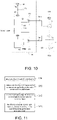
- FIG. 10 is a schematic circuit block view of the control circuit 110, the driving circuit 120, and the light-emitting device 130 depicted in FIG. 1 according to still another embodiment of the invention.
- the driving circuit 120 shown in FIG. 10 includes the current source 121 and the power switch 122.
- the current source 121 correspondingly provides the driving current according to the bias voltage Vbias.
- the first terminal of the power switch 122 is coupled to the current providing terminal of the current source 121, so as to receive the driving current.
- the second terminal of the power switch 122 is coupled to the light-emitting device 130.
- the power switch 122 determines whether to transmit the driving current of the current source 121 to the light-emitting device 130 according to the switch signal Vsw, so as to generate the projected beam.
- the related descriptions of the light-emitting device 130 depicted in FIG. 10 can be found in the descriptions of the light-emitting device 130 depicted in FIG. 8 or the descriptions of the light-emitting device 130 depicted in FIG. 9 and thus will be further provided.
- the first terminal (e.g., the anode) of the LED 131 of the light-emitting device 130 depicted in FIG. 10 is coupled to the second terminal of the power switch 122, so as to receive the power voltage VDDA.
- the second terminal (e.g., the cathode) of the LED 131 is coupled to the reference voltage VSSA (e.g., the ground voltage or any other fixed voltage).
- VSSA reference voltage
- the way to operate the driving circuit 120 and the light-emitting device 130 should not be limited to those provided in the embodiment depicted in FIG. 10 .
- the second terminal (e.g., the anode) of the LED 131 is coupled to the power voltage VDDA
- the current obtaining terminal of the current source 121 is coupled to the first terminal of the power switch 122
- the current providing terminal of the current source 121 is coupled to the reference voltage VSSA.
- the control circuit 110 includes the voltage generating circuit 111, the bias circuit 112, the switch 113, the controller 114, the pulse width modulation circuit 115, and the switch 116.
- the related descriptions of the voltage generating circuit 111, the bias circuit 112, the switch 113, and the controller 114 depicted in FIG. 10 can be found in the descriptions of the voltage generating circuit 111, the bias circuit 112, the switch 113, and the controller 114 depicted in FIG. 8 , and the related descriptions of the controller 114, the pulse width modulation circuit 115, and the switch 116 depicted in FIG. 10 can be found in the descriptions of the controller 114, the pulse width modulation circuit 115, and the switch 116 depicted in FIG. 9 and thus will not be further provided.
- the controller 114 is configured to analyze the color content of the video frame, so as to select one of the highlight mode and the normal mode as the selected mode.
- the controller 114 controls the switch 113 to transmit the fixed voltage VI to the current source 121 as the bias voltage Vbias, and the controller 114 controls the switch 116 to transmit the fixed voltage (e.g., the power voltage VDDA) to the control terminal of the power switch 122 as the switch signal Vsw.
- the controller 114 controls the switch 113 to transmit the dynamic voltage V2 to the current source 121 as the bias voltage Vbias, and the controller 114 controls the switch 116 to transmit the pulse width modulation signal VPWM to the control terminal of the power switch 122 as the switch signal Vsw.
- the fixed voltage VI is greater than the dynamic voltage V2
- the duty ratio of the power voltage VDDD is greater than the duty ratio of the pulse width modulation signal VPWM.
- the brightness of the projected beam of the LED 131 in the highlight mode is greater than the brightness of the projected beam of the LED 131 in the normal mode.
- FIG. 11 is a schematic flowchart of an operation method of a projection apparatus according to another embodiment of the invention.
- the control circuit 110 analyzes color content of at least one video frame.
- the control circuit 110 selects one of a highlight mode and a normal mode as a selected mode.
- the control circuit 110 correspondingly sets at least one control signal Sc to the driving circuit 120 according to the selected mode.
- the driving circuit 120 drives the light-emitting device 130 to generate a projected beam.
- a brightness of the projected beam of the light-emitting device 130 in the highlight mode is greater than the brightness of the projected beam of the light-emitting device 130 in the normal mode.
- the step S720 includes the following: when the color content of the video frame indicates that the video frame is the white image frame, the control circuit 110 selects the highlight mode as the selected mode; when the color content of the video frame indicates that the video frame is not the white image frame, the control circuit 110 selects the normal mode as the selected mode.
- the step S720 includes the following: when the color content of the video frame indicates that the video frame is the white image frame, an operation mode of the control circuit 110 is switched from the normal mode to the highlight mode; when a non-white object shows up in the white image frame, or when the color content of the video frame indicates that the video frame is no longer the white image frame, the operation mode of the control circuit 110 is switched from the highlight mode to the normal mode.
- a ratio of the number of the red sub-pixels satisfying the condition to the number of all red sub-pixels in the video frame is a first ratio; if a green sub-pixel satisfies a condition that a gray scale of the green sub-pixel is greater than a green threshold, a ratio of the number of the green sub-pixels satisfying the condition to the number of all green sub-pixels in the video frame is a second ratio; if a blue sub-pixel satisfies a condition that a gray scale of the blue sub-pixel is greater than a blue threshold, a ratio of the number of the blue sub-pixels satisfying the condition to the number of all blue sub-pixels in the video frame is a third ratio.
- the step S720 includes the following: when the first ratio is greater than the first ratio threshold, the second ratio is greater than the second ratio threshold, and the third ratio is greater than the third ratio threshold, the control circuit 110 selects the highlight mode as the selected mode; when the first ratio is less than the first ratio threshold, the second ratio is less than the second ratio threshold, and the third ratio is less than the third ratio threshold, the control circuit 110 selects the normal mode as the selected mode.
- the light-emitting device 130 includes the red LED, the green LED, and the blue LED. In other embodiments, the light-emitting device 130 further includes the white LED.
- the light-emitting period of the red LED, the light-emitting period of the green LED, and the light-emitting period of the blue LED are completely overlapped.
- the light-emitting period of the blue LED and the light-emitting period of the red LED are not overlapped, and the light-emitting period of the blue LED and the light-emitting period of the green LED are not overlapped.
- the light-emitting period of the white LED, the light-emitting period of the red LED, the light-emitting period of the green LED, and the light-emitting period of the blue LED are completely overlapped.
- control signal Sc includes the first switch signal associated with the red LED, the second switch signal associated with the green LED, and the third switch signal associated with the blue LED.
- the duty ratio of the first switch signal, the duty ratio of the second switch signal, and the duty ratio of the third switch signal are all 100%.
- the duty ratio of at least one of the first switch signal, the second switch signal, and the third switch signal is less than 100%.
- the control signal Sc includes the first bias voltage, the second bias voltage, and the third bias voltage.
- the first bias voltage controls the first current source associated with the red LED
- the second bias voltage controls the second current source associated with the green LED
- the third bias voltage controls the third current source associated with the blue LED.
- the first bias voltage is the first fixed voltage
- the second bias voltage is the second fixed voltage
- the third bias voltage is the third fixed voltage.
- the first bias voltage is a first dynamic voltage less than the first fixed voltage
- the second bias voltage is a second dynamic voltage less than the second fixed voltage
- the third bias voltage is a third dynamic voltage less than the third fixed voltage.
- the driving circuit 120 includes the current source 121.
- the current source 121 correspondingly provides the driving current to the light-emitting device 130 according to the bias voltage Vbais to generate the projected beam.
- the step S730 includes the following: generating by the bias circuit 112 the dynamic voltage V2 less than the fixed voltage VI; controlling the switch 113 by the controller 114, wherein the first selection terminal of the switch 113 is coupled to the fixed voltage V1, the second selection terminal of the switch 113 is coupled to the bias circuit 112 to receive the dynamic voltage V2, the common terminal of the switch 113 is coupled to the current source 121 to provide the bias voltage Vbias, and the controller 114 analyzes the color content of the video frame to select one of the highlight mode and the normal mode as the selected mode; in the highlight mode, the fixed voltage VI is transmitted to the current source 121 as the bias voltage Vbias through the switch 113; in the normal mode, the dynamic voltage V2 is transmitted to the current source 121 as the bias voltage Vbias through the switch 113.
- the driving circuit 120 includes the power switch 122.
- the first terminal and the second terminal of the power switch 122 are respectively coupled to the power voltage VDDA and the light-emitting device 130.
- the power switch 122 determines whether to transmit the power voltage VDDA to the light-emitting device 130 according to the switch signal Vsw, so as to generate the projected beam.
- the step S730 includes the following: generating the pulse width modulation signal VPWM by the pulse width modulation circuit 115, wherein a duty ratio of the pulse width modulation signal VPWM is less than 100%; controlling the switch 116 by the controller 114, wherein the first selection terminal of the switch 116 is coupled to the fixed voltage (e.g., the power voltage VDDA), the second selection terminal of the switch 116 is coupled to the pulse width modulation circuit 115 to receive the pulse width modulation signal VPWM, and the common terminal of the switch 116 is coupled to the control terminal of the power switch 122 to provide the switch signal Vsw; analyzing by the controller 114 the color content of the video frame to select one of the highlight mode and the normal mode as the selected mode; in the highlight mode, transmitting the fixed voltage (e.g., the power voltage VDDA) to the control terminal of the power switch 122 as the switch signal Vsw through the switch 116; in the normal mode, transmitting the pulse width modulation signal VPWM to the control terminal
- the driving circuit 120 includes the current source 121 and the power switch 122.
- the current source 121 correspondingly provides the driving current according to the bias voltage Vbias.
- the first terminal of the power switch 122 is coupled to the current source 121 to receive the driving current.
- the second terminal of the power switch 122 is coupled to the light-emitting device 130.
- the power switch 122 determines whether to transmit the driving current of the current source 121 to the light-emitting device 130 according to the switch signal Vsw, so as to generate the projected beam.
- the step S730 includes the following: generating by the bias circuit 112 the dynamic voltage V2 less than the fixed voltage VI; controlling the switch 113 by the controller 114, wherein the first selection terminal of the switch 113 is coupled to the fixed voltage V1, the second selection terminal of the switch 113 is coupled to the bias circuit 112 to receive the dynamic voltage V2, the common terminal of the switch 113 is coupled to the current source 121 to provide the bias voltage Vbias, and the controller 114 analyzes the color content of the video frame to select one of the highlight mode and the normal mode as the selected mode; generating by the pulse width modulation circuit 115 the pulse width modulation signal VPWM, wherein the duty ratio of the pulse width modulation signal VPWM is less than 100%; controlling the switch 116 by the controller, wherein the first selection terminal of the switch 116 is coupled to the fixed voltage (e.g., the power voltage VDDA), the second selection terminal of the switch 116 is coupled to the pulse width modulation circuit 115 to receive the pulse width modulation signal VPWM,
- the operation method further includes: receiving a user's command by a user interface circuit; transmitting the user's command to the control circuit; selecting by the control circuit one of the highlight mode and the normal mode as the selected mode according to the user's command.
- the block of the control circuit 110 and/or the controller 114 may be implemented in form of one or a combination of hardware, firmware, and software (i.e., programs).
- the block of the control circuit 110 and/or the controller 114 may be implemented in form of a logic circuit on an integrated circuit.
- the control circuit 110 and/or controller 114 may be implemented in form of hardware through hardware description languages (e.g., Verilog HDL or VHDL) or other appropriate programming languages.
- control circuit 110 and/or the controller 114 may be implemented by one or more controllers, micro-controllers, micro-processors, application-specific integrated circuits (ASIC), digital signal processors (DSP), field programmable gate array (FPGA), and/or logic blocks, modules, and circuits in other processing units.
- ASIC application-specific integrated circuits
- DSP digital signal processors
- FPGA field programmable gate array
- one or more embodiments provided herein have at least one of the following advantages or achieve at least one of the following effects.
- the color content of the video frame can be analyzed.
- the projection apparatus 100 can switch the operation mode to one of the highlight mode and the normal mode.
- the projection apparatus 100 is able to dynamically increase the brightness of the projected beam of the light-emitting device according to actual scenarios.
Landscapes
- Engineering & Computer Science (AREA)
- Multimedia (AREA)
- Signal Processing (AREA)
- Physics & Mathematics (AREA)
- General Physics & Mathematics (AREA)
- Computer Vision & Pattern Recognition (AREA)
- Theoretical Computer Science (AREA)
- Human Computer Interaction (AREA)
- Control Of Indicators Other Than Cathode Ray Tubes (AREA)
- Projection Apparatus (AREA)
- Video Image Reproduction Devices For Color Tv Systems (AREA)
Claims (14)
- Projektionsvorrichtung, die eine lichtaussendende Vorrichtung (130), eine Ansteuerungsschaltung (120) und eine Steuerschaltung (110) umfasst,wobei die Ansteuerungsschaltung (120) an die lichtaussendende Vorrichtung (130) gekoppelt ist und konfiguriert ist, die lichtausendende Vorrichtung (130) gemäß mindestens einem Steuersignal anzusteuern, um einen projizierten Strahl zu erzeugen,wobei die Steuerschaltung (110) konfiguriert ist:mindestens einen Videorahmen zu empfangen,Farbinhalt des mindestens einen Videorahmens zu analysieren,eine Hervorhebungsbetriebsart oder eine normale Betriebsart als eine ausgewählte Betriebsart gemäß dem Farbinhalt auszuwählen unddas mindestens eine Steuersignal für die Ansteuerungsschaltung (120) gemäß der ausgewählten Betriebsart entsprechend einzustellen, undwobei eine Helligkeit des projizierten Strahls der lichtausendenden Vorrichtung (130) in der Hervorhebungsbetriebsart größer als eine Helligkeit des projizierten Strahls der lichtaussendenden Vorrichtung (130) in der normalen Betriebsart ist,dadurch gekennzeichnet, dass:ein Verhältnis einer Anzahl roter Unterpixel, die eine Bedingung erfüllen, dass eine Grauskala eines roten Unterpixels größer als ein roter Schwellenwert in dem mindestens einen Videorahmen ist, zu einer Anzahl aller roten Unterpixel in dem mindestens einen Videorahmen ein erstes Verhältnis ist,ein Verhältnis einer Anzahl grüner Unterpixel, die eine Bedingung erfüllen, dass eine Grauskala eines grünen Unterpixels größer als ein grüner Schwellenwert in dem mindestens einen Videorahmen ist, zu einer Anzahl aller grünen Unterpixel in dem mindestens einen Videorahmen ein zweites Verhältnis ist,ein Verhältnis einer Anzahl blauer Unterpixel, die eine Bedingung erfüllen, dass eine Grauskala eines blauen Unterpixels größer als ein blauer Schwellenwert in dem mindestens einen Videorahmen ist, zu einer Anzahl aller blauen Unterpixel in dem mindestens einen Videorahmen ein drittes Verhältnis ist,wobei dann, wenn das erste Verhältnis größer als ein erster Verhältnisschwellenwert ist, das zweite Verhältnis größer als ein zweiter Verhältnisschwellenwert ist und das dritte Verhältnis größer als ein dritter Verhältnisschwellenwert ist, die Steuerschaltung die Hervorhebungsbetriebsart als die ausgewählte Betriebsart auswählt, undund dann, wenn das erste Verhältnis kleiner als der erste Verhältnisschwellenwert ist, das zweite Verhältnis kleiner als der zweite Verhältnisschwellenwert ist oder das dritte Verhältnis kleiner als der dritte Verhältnisschwellenwert ist, die Steuerschaltung die normale Betriebsart als die ausgewählte Betriebsart auswählt.
- Projektionsvorrichtung nach Anspruch 1, wobei eine Betriebsart der Steuerschaltung (110) zu der Hervorhebungsbetriebsart geschaltet wird, wenn der Farbinhalt des mindestens einen Videorahmens angibt, dass der mindestens eine Videorahmen ein weißer Bildrahmen ist.
- Projektionsvorrichtung nach Anspruch 1 oder 2, wobei dann, wenn ein nicht weißes Objekt in dem weißen Bildrahmen auftaucht oder wenn der Farbinhalt des mindestens einen Videorahmens angibt, dass der mindestens eine Videorahmen nicht länger der weiße Bildrahmen ist, eine Betriebsart der Steuerschaltung (110) zu der normalen Betriebsart geschaltet wird.
- Projektionsvorrichtung nach einem der vorhergehenden Ansprüche, wobei die lichtaussendende Vorrichtung (130) eine rotes Licht aussendende Diode, eine grünes Licht aussendende Diode und eine blaues Licht aussendende Diode umfasst.
- Projektionsvorrichtung nach Anspruch 4, wobei sich in der Hervorhebungsbetriebsart eine Lichtaussendungsperiode der rotes Licht aussendenden Diode, eine Lichtaussendungsperiode der grünes Licht aussendenden Diode und eine Lichtaussendungsperiode der blaues Licht aussendenden Diode vollständig überschneiden.
- Projektionsvorrichtung nach Anspruch 4, wobei die lichtaussendende Vorrichtung (130) ferner eine weißes Licht aussendende Diode umfasst und sich eine Lichtaussendungsperiode der weißes Licht aussendenden Diode, eine Lichtaussendungsperiode der rotes Licht aussendenden Diode, eine Lichtaussendungsperiode der grünes Licht aussendenden Diode und eine Lichtaussendungsperiode der blaues Licht aussendenden Diode in der Hervorhebungsbetriebsart vollständig überschneiden.
- Projektionsvorrichtung nach Anspruch 4, wobeidas mindestens eine Steuersignal ein erstes Schaltsignal, das der rotes Licht aussenden Diode zugeordnet ist, ein zweites Schaltsignal, das der grünes Licht aussendenden Diode zugeordnet ist, und ein drittes Schaltsignal, das der blaues Licht aussendenden Diode zugeordnet ist, umfasst undeine relative Einschaltdauer des ersten Schaltsignals, eine relative Einschaltdauer des zweiten Schaltsignals und eine relative Einschaltdauer des dritten Schaltsignals alle 100% in der Hervorhebungsbetriebsart sind.
- Projektionsvorrichtung nach Anspruch 4, wobei ein Überschneidungsverhältnis zweier einer Aktivierungsperiode der rotes Licht aussendenden Diode, einer Aktivierungsperiode der grünes Licht aussendenden Diode und einer Aktivierungsperiode der blaues Licht aussendenden Diode von 0% bis 40% in der normalen Betriebsart ist.
- Projektionsvorrichtung nach Anspruch 4, wobeidas mindestens eine Steuersignal eine erste Vorspannung, eine zweite Vorspannung und eine dritte Vorspannung umfasst, wobei die erste Vorspannung eine erste Stromquelle steuert, die der rotes Licht aussendenden Diode zugeordnet ist, die zweite Vorspannung eine zweite Stromquelle steuert, die der grünes Licht aussendenden Diode zugeordnet ist, und die dritte Vorspannung eine dritte Stromquelle steuert, die der blaues Licht aussendenden Diode zugeordnet ist,wobei in der Hervorhebungsbetriebsart die erste Vorspannung eine erste festgelegte Spannung ist, die zweite Vorspannung eine zweite festgelegte Spannung ist und die dritte Vorspannung eine dritte festgelegte Spannung ist,wobei in der normalen Betriebsart die erste Vorspannung eine erste dynamische Spannung ist, die kleiner als die erste festgelegte Spannung ist, die zweite Vorspannung eine zweite dynamische Spannung ist, die kleiner als die zweite festgelegte Spannung ist, und die dritte Vorspannung eine dritte dynamische Spannung ist, die kleiner als die dritte festgelegte Spannung ist.
- Projektionsvorrichtung nach Anspruch 1, wobei die Ansteuerungsschaltung (120) eine Stromquelle (121) umfasst, wobei die Stromquelle (121) entsprechend einen Ansteuerungsstrom an die lichtausendende Vorrichtung (130) gemäß einer Vorspannung liefert, um den projizierten Strahl zu erzeugen, und die Steuerschaltung (110) eine Vorspannungsschaltung (112), einen Schalter (113) und eine Steuereinheit (114) umfasst,wobei die Vorspannungsschaltung (112) konfiguriert ist, eine dynamische Spannung zu erzeugen, die kleiner als eine festgelegte Spannung ist;wobei der Schalter (113) einen ersten Auswahlanschluss, einen zweiten Auswahlanschluss und einen gemeinsamen Anschluss besitzt, wobei der erste Auswahlanschluss an die festgelegte Spannung gekoppelt ist, der zweite Auswahlanschluss an die Vorspannungsschaltung gekoppelt ist, um die dynamische Spannung zu empfangen, und der gemeinsame Anschluss an die Stromquelle gekoppelt ist, um die Vorspannung zu liefern,wobei die Steuereinheit (114) konfiguriert ist, den Farbinhalt des mindestens einen Videorahmens zu analysieren, um die Hervorhebungsbetriebsart oder die normale Betriebsart als die ausgewählte Betriebsart auszuwählen,wobei die Steuereinheit (114) konfiguriert ist, den Schalter (113) zu steuern, die festgelegte Spannung an die Stromquelle (121) als die Vorspannung in der Hervorhebungsbetriebsart zu senden;wobei die Steuereinheit (114) konfiguriert ist, den Schalter (113) zu steuern, die dynamische Spannung an die Stromquelle (121) als die Vorspannung in der normalen Betriebsart zu senden.
- Projektionsvorrichtung nach Anspruch 1, wobei die Ansteuerungsschaltung (120) einen Leistungsschalter (122) umfasst, wobei ein erster Anschluss und ein zweiter Anschluss des Leistungsschalters (122) jeweils an eine Leistungsspannung und die lichtaussendende Vorrichtung (130) gekoppelt sind, wobei der Leistungsschalter (122) konfiguriert ist, gemäß einem Schaltsignal zu bestimmen, ob die Leistungsspannung an die lichtaussendende Vorrichtung (130) zu senden ist, um den projizierten Strahl zu erzeugen, und die Steuerschaltung (110) eine Impulsbreitenmodulationsschaltung (115), einen Schalter (113) und eine Steuereinheit (114) umfasst,wobei die Impulsbreitenmodulationsschaltung (115) konfiguriert ist, ein Impulsbreitenmodulationssignal zu erzeugen, und eine relative Einschaltdauer des Impulsbreitenmodulationssignals kleiner als 100% ist,wobei der Schalter (113) einen ersten Auswahlanschluss, einen zweiten Auswahlanschluss und einen gemeinsamen Anschluss besitzt, wobei der erste Auswahlanschluss an eine festgelegte Spannung gekoppelt ist, der zweite Auswahlanschluss an die Impulsbreitenmodulationsschaltung gekoppelt ist, um das Impulsbreitenmodulationssignal zu empfangen, und der gemeinsame Anschluss an einen Steueranschluss des Leistungsschalters (122) gekoppelt ist, um das Schaltsignal zu liefern,wobei die Steuereinheit (114) konfiguriert ist, den Farbinhalt des mindestens einen Videorahmens zu analysieren, um die Hervorhebungsbetriebsart oder die normale Betriebsart als die ausgewählte Betriebsart auszuwählen, wobei die Steuereinheit (114) konfiguriert ist, den Schalter (113) zu steuern, die festgelegte Spannung an den Steueranschluss des Leistungsschalters (122) als das Schaltsignal in der Hervorhebungsbetriebsart zu senden, und die Steuereinheit (114) konfiguriert ist, den Schalter (113) zu steuern, das Impulsbreitenmodulationssignal an den Steueranschluss des Leistungsschalters (122) als das Schaltsignal in der normalen Betriebsart zu senden.
- Projektionsvorrichtung nach Anspruch 1, wobei die Ansteuerungsschaltung (110) eine Stromquelle (121) und einen Leistungsschalter (122) umfasst, wobei die Stromquelle (121) entsprechend einen Ansteuerungsstrom gemäß einer Vorspannung liefert, wobei ein erster Anschluss des Leistungsschalters an die Stromquelle (121) gekoppelt ist, um den Ansteuerungsstrom zu empfangen, ein zweiter Anschluss des Leistungsschalters (122) an die lichtaussendende Vorrichtung (130) gekoppelt ist, der Leistungsschalter (122) konfiguriert ist, gemäß einem Schaltsignal zu bestimmen, ob der Ansteuerungsstrom an die lichtaussendende Vorrichtung (130) zu senden ist, um den projizierten Strahl zu erzeugen, und die Steuerschaltung (110) eine Vorspannungsschaltung (112), einen ersten Schalter, eine Impulsbreitenmodulationsschaltung (115), einen zweiten Schalter und eine Steuereinheit (114) umfasst,wobei die Vorspannungsschaltung (112) konfiguriert ist, eine dynamische Spannung, die kleiner als eine erste festgelegte Spannung ist, zu erzeugen,wobei der erste Schalter einen ersten Auswahlanschluss, einen zweiten Auswahlanschluss und einen gemeinsamen Anschluss besitzt, wobei der erste Auswahlanschluss des ersten Schalters an die erste festgelegte Spannung gekoppelt ist, der zweite Auswahlanschluss des ersten Schalters an die Vorspannungsschaltung gekoppelt ist, um die dynamische Spannung zu empfangen, und der gemeinsame Anschluss des ersten Schalters an die Stromquelle (121) gekoppelt ist, um die Vorspannung zu liefern;wobei die Impulsbreitenmodulationsschaltung (115) konfiguriert ist, ein Impulsbreitenmodulationssignal zu erzeugen, und eine relative Einschaltdauer des Impulsbreitenmodulationssignals kleiner als 100% ist,wobei der zweite Schalter einen ersten Auswahlanschluss, einen zweiten Auswahlanschluss und einen gemeinsamen Anschluss besitzt, wobei der erste Auswahlanschluss des zweiten Schalters an eine zweite festgelegte Spannung gekoppelt ist, der zweite Auswahlanschluss des zweiten Schalters an die Impulsbreitenmodulationsschaltung gekoppelt ist, um das Impulsbreitenmodulationssignal zu empfangen, und der gemeinsame Anschluss des zweiten Schalters an einen Steueranschluss des Leistungsschalters gekoppelt ist, um das Schaltsignal zu liefern,wobei die Steuereinheit (114) konfiguriert ist, den Farbinhalt des mindestens einen Videorahmens zu analysieren, um die Hervorhebungsbetriebsart oder die normale Betriebsart als die ausgewählte Betriebsart auszuwählen,wobei die Steuereinheit (114) in der Hervorhebungsbetriebsart konfiguriert ist, den ersten Schalter zu steuern, die erste festgelegte Spannung an die Stromquelle (121) als die Vorspannung zu senden, und die Steuereinheit (114) konfiguriert ist, den zweiten Schalter zu steuern, die zweite festgelegte Spannung an den Steueranschluss des Leistungsschalters (122) als das Schaltsignal zu senden,wobei in der normalen Betriebsart die Steuereinheit (114) konfiguriert ist, den ersten Schalter zu steuern, die dynamische Spannung an die Stromquelle (121) als die Vorspannung zu senden, und die Steuereinheit (114) konfiguriert ist, den zweiten Schalter zu steuern, das Impulsbreitenmodulationssignal an den Steueranschluss des Leistungsschalters als das Schaltsignal zu senden.
- Projektionsvorrichtung nach einem der vorhergehenden Ansprüche, die ferner umfasst:eine Anwenderschnittstellenschaltung (140), die konfiguriert ist, einen Befehl eines Anwenders zu empfangen und den Befehl des Anwenders an die Steuerschaltung (110) zu senden,wobei die Steuerschaltung (110) konfiguriert ist, die Hervorhebungsbetriebsart oder die normale Betriebsart als die ausgewählte Betriebsart gemäß dem Befehl des Anwenders auszuwählen.
- Betriebsverfahren einer Projektionsvorrichtung, das umfasst:Ansteuern einer lichtaussendenden Vorrichtung (130) durch eine Ansteuerungsschaltung (120) gemäß mindestens einem Steuersignal, um einen projizierten Strahl zu erzeugen;Analysieren eines Farbinhalts des mindestens einen Videorahmens durch eine Steuerschaltung (110); undAuswählen durch die Steuerschaltung (110) einer Hervorhebungsbetriebsart oder einer normalen Betriebsart als eine ausgewählte Betriebsart gemäß dem Farbinhalt und entsprechend Einstellen des mindestens einen Steuersignals für die Ansteuerungsschaltung (120) gemäß der ausgewählten Betriebsart,wobei eine Helligkeit des projizierten Strahls der lichtaussendenden Vorrichtung (130) in der Hervorhebungsbetriebsart größer als eine Helligkeit des projizierten Strahls der lichtaussendenden Vorrichtung (130) in der normalen Betriebsart ist,dadurch gekennzeichnet, dass:ein Verhältnis einer Anzahl roter Unterpixel, die eine Bedingung erfüllen, dass eine Grauskala eines roten Unterpixels größer als ein roter Schwellenwert in dem mindestens einen Videorahmen ist, zu einer Anzahl aller roten Unterpixel in dem mindestens einen Videorahmen ein erstes Verhältnis ist,ein Verhältnis einer Anzahl grüner Unterpixel, die eine Bedingung erfüllen, dass eine Grauskala eines grünen Unterpixels größer als ein grüner Schwellenwert in dem mindestens einen Videorahmen ist, zu einer Anzahl aller grünen Unterpixel in dem mindestens einen Videorahmen ein zweites Verhältnis ist,ein Verhältnis einer Anzahl blauer Unterpixel, die eine Bedingung erfüllen, dass eine Grauskala eines blauen Unterpixels größer als ein blauer Schwellenwert in dem mindestens einen Videorahmen ist, zu einer Anzahl aller blauen Unterpixel in dem mindesteins einen Videorahmen ein drittes Verhältnis ist,wobei dann, wenn das erste Verhältnis größer als ein erster Verhältnisschwellenwert ist, das zweite Verhältnis größer als ein zweiter Verhältnisschwellenwert ist und das dritte Verhältnis größer als ein dritter Verhältnisschwellenwert ist, die Steuerschaltung die Hervorhebungsbetriebsart als die ausgewählte Betriebsart auswählt, undund dann, wenn das erste Verhältnis kleiner als der erste Verhältnisschwellenwert ist, das zweite Verhältnis kleiner als der zweite Verhältnisschwellenwert ist oder das dritte Verhältnis kleiner als der dritte Verhältnisschwellenwert ist, die Steuerschaltung die normale Betriebsart als die ausgewählte Betriebsart auswählt.
Applications Claiming Priority (2)
| Application Number | Priority Date | Filing Date | Title |
|---|---|---|---|
| CN201811406177 | 2018-11-23 | ||
| CN201811582405.5A CN111223427B (zh) | 2018-11-23 | 2018-12-24 | 投射装置及其操作方法 |
Publications (3)
| Publication Number | Publication Date |
|---|---|
| EP3668090A2 EP3668090A2 (de) | 2020-06-17 |
| EP3668090A3 EP3668090A3 (de) | 2020-08-26 |
| EP3668090B1 true EP3668090B1 (de) | 2022-11-02 |
Family
ID=68654331
Family Applications (1)
| Application Number | Title | Priority Date | Filing Date |
|---|---|---|---|
| EP19210804.1A Active EP3668090B1 (de) | 2018-11-23 | 2019-11-22 | Projektionsvorrichtung und betriebsverfahren dafür |
Country Status (2)
| Country | Link |
|---|---|
| US (1) | US11070777B2 (de) |
| EP (1) | EP3668090B1 (de) |
Families Citing this family (3)
| Publication number | Priority date | Publication date | Assignee | Title |
|---|---|---|---|---|
| CN116794917A (zh) * | 2022-03-18 | 2023-09-22 | 中强光电股份有限公司 | 投影装置及其照明装置与光源驱动方法 |
| CN115981088B (zh) * | 2023-02-16 | 2026-01-30 | 青岛海信激光显示股份有限公司 | 激光投影设备及其光源的驱动方法 |
| TWI862050B (zh) * | 2023-07-31 | 2024-11-11 | 聚積科技股份有限公司 | 電流驅動裝置與調光方法 |
Family Cites Families (10)
| Publication number | Priority date | Publication date | Assignee | Title |
|---|---|---|---|---|
| US6894675B2 (en) * | 2002-01-22 | 2005-05-17 | Koninklijke Philips Electronics N.V. | Seamless highlighting in LCD monitors and LCD-TV |
| US7019736B2 (en) | 2002-03-20 | 2006-03-28 | Hewlett-Packard Development Company, L.P. | Method and apparatus for image display |
| US8098265B2 (en) | 2008-10-10 | 2012-01-17 | Ostendo Technologies, Inc. | Hierarchical multicolor primaries temporal multiplexing system |
| EP2472316B1 (de) | 2009-09-28 | 2019-12-11 | Nec Corporation | Lichtquellenvorrichtung und projektionsanzeigevorrichtung damit |
| JP5273197B2 (ja) | 2011-05-13 | 2013-08-28 | ウシオ電機株式会社 | 高圧放電ランプ用給電装置 |
| JPWO2014171134A1 (ja) * | 2013-04-18 | 2017-02-16 | パナソニックIpマネジメント株式会社 | 投写型映像表示装置 |
| CN104298982B (zh) | 2013-07-16 | 2019-03-08 | 深圳市腾讯计算机系统有限公司 | 一种文字识别方法及装置 |
| US9706180B2 (en) | 2015-03-23 | 2017-07-11 | Panasonic Intellectual Property Management Co., Ltd. | Projection display apparatus |
| WO2018025390A1 (ja) | 2016-08-05 | 2018-02-08 | マクセル株式会社 | 投射型映像表示装置 |
| US10511729B1 (en) * | 2018-05-31 | 2019-12-17 | Kyocera Document Solutions Inc. | Image forming apparatus, image forming system, and communication processing method implemented guidance mode for remote maintenance |
-
2019
- 2019-11-20 US US16/690,101 patent/US11070777B2/en active Active
- 2019-11-22 EP EP19210804.1A patent/EP3668090B1/de active Active
Also Published As
| Publication number | Publication date |
|---|---|
| US11070777B2 (en) | 2021-07-20 |
| US20200169708A1 (en) | 2020-05-28 |
| EP3668090A3 (de) | 2020-08-26 |
| EP3668090A2 (de) | 2020-06-17 |
Similar Documents
| Publication | Publication Date | Title |
|---|---|---|
| CN101253776B (zh) | 投影仪和控制用于该投影仪的光源的方法 | |
| US10051247B2 (en) | Image projection apparatus | |
| JP6201287B2 (ja) | 表示装置、及び、表示装置の制御方法 | |
| US9257096B2 (en) | Display system | |
| US9064443B2 (en) | Projection apparatus, projection method, and storage medium storing program, for reducing energy consumption by shortening color mixing period | |
| US11070777B2 (en) | Projection apparatus and operation method thereof | |
| JP7385441B2 (ja) | 投射装置及びその操作方法 | |
| US10986707B2 (en) | Display device | |
| WO2014162590A1 (ja) | プロジェクタおよびその制御方法 | |
| CN116746280A (zh) | 用于机动车的照明设备、特别是高分辨率的前照灯 | |
| JP2009175627A (ja) | 画像表示装置および電子機器 | |
| US20060193357A1 (en) | Light emitting device driver circuit | |
| US10148921B2 (en) | Projection device, projection control method and storage medium | |
| CN209571215U (zh) | 投射装置 | |
| US12444348B2 (en) | Display system | |
| JP2007059139A (ja) | 光源装置 | |
| CN101467489A (zh) | 照明设备 | |
| JP2009116200A (ja) | 映像表示装置、映像処理方法、及びコンピュータプログラム | |
| US11783785B2 (en) | LED device having diodes controlled by different signals, operating method of the same, and display device | |
| JP2016213171A (ja) | 光源制御装置、光源制御方法、およびプロジェクタ | |
| US12555532B2 (en) | Optimized pixel performance in a display system | |
| US9125262B2 (en) | Circuit configuration for operating LEDs for a micromirror arrangement | |
| KR20070027555A (ko) | 컬러 디스플레이 | |
| JP2017204389A (ja) | 光源装置、表示装置およびヘッドアップディスプレイ装置 | |
| JP2017227783A (ja) | 光源装置、投影装置、光源制御方法及びプログラム |
Legal Events
| Date | Code | Title | Description |
|---|---|---|---|
| PUAI | Public reference made under article 153(3) epc to a published international application that has entered the european phase |
Free format text: ORIGINAL CODE: 0009012 |
|
| STAA | Information on the status of an ep patent application or granted ep patent |
Free format text: STATUS: THE APPLICATION HAS BEEN PUBLISHED |
|
| AK | Designated contracting states |
Kind code of ref document: A2 Designated state(s): AL AT BE BG CH CY CZ DE DK EE ES FI FR GB GR HR HU IE IS IT LI LT LU LV MC MK MT NL NO PL PT RO RS SE SI SK SM TR |
|
| AX | Request for extension of the european patent |
Extension state: BA ME |
|
| PUAL | Search report despatched |
Free format text: ORIGINAL CODE: 0009013 |
|
| AK | Designated contracting states |
Kind code of ref document: A3 Designated state(s): AL AT BE BG CH CY CZ DE DK EE ES FI FR GB GR HR HU IE IS IT LI LT LU LV MC MK MT NL NO PL PT RO RS SE SI SK SM TR |
|
| AX | Request for extension of the european patent |
Extension state: BA ME |
|
| RIC1 | Information provided on ipc code assigned before grant |
Ipc: H05B 45/10 20200101ALN20200720BHEP Ipc: H04N 9/31 20060101AFI20200720BHEP |
|
| STAA | Information on the status of an ep patent application or granted ep patent |
Free format text: STATUS: REQUEST FOR EXAMINATION WAS MADE |
|
| 17P | Request for examination filed |
Effective date: 20210224 |
|
| RBV | Designated contracting states (corrected) |
Designated state(s): AL AT BE BG CH CY CZ DE DK EE ES FI FR GB GR HR HU IE IS IT LI LT LU LV MC MK MT NL NO PL PT RO RS SE SI SK SM TR |
|
| RIC1 | Information provided on ipc code assigned before grant |
Ipc: H05B 45/10 20200101ALN20220517BHEP Ipc: H04N 9/31 20060101AFI20220517BHEP |
|
| GRAP | Despatch of communication of intention to grant a patent |
Free format text: ORIGINAL CODE: EPIDOSNIGR1 |
|
| STAA | Information on the status of an ep patent application or granted ep patent |
Free format text: STATUS: GRANT OF PATENT IS INTENDED |
|
| INTG | Intention to grant announced |
Effective date: 20220624 |
|
| RIN1 | Information on inventor provided before grant (corrected) |
Inventor name: WANG, CHIH-LIN Inventor name: CHEN, JUNG-CHI Inventor name: WU, PO-YEN Inventor name: CHIU, SHENG-YU Inventor name: SU, WEI-CHIH |
|
| GRAS | Grant fee paid |
Free format text: ORIGINAL CODE: EPIDOSNIGR3 |
|
| GRAA | (expected) grant |
Free format text: ORIGINAL CODE: 0009210 |
|
| STAA | Information on the status of an ep patent application or granted ep patent |
Free format text: STATUS: THE PATENT HAS BEEN GRANTED |
|
| AK | Designated contracting states |
Kind code of ref document: B1 Designated state(s): AL AT BE BG CH CY CZ DE DK EE ES FI FR GB GR HR HU IE IS IT LI LT LU LV MC MK MT NL NO PL PT RO RS SE SI SK SM TR |
|
| REG | Reference to a national code |
Ref country code: GB Ref legal event code: FG4D |
|
| REG | Reference to a national code |
Ref country code: CH Ref legal event code: EP Ref country code: AT Ref legal event code: REF Ref document number: 1529627 Country of ref document: AT Kind code of ref document: T Effective date: 20221115 |
|
| REG | Reference to a national code |
Ref country code: DE Ref legal event code: R096 Ref document number: 602019021389 Country of ref document: DE |
|
| REG | Reference to a national code |
Ref country code: IE Ref legal event code: FG4D |
|
| REG | Reference to a national code |
Ref country code: LT Ref legal event code: MG9D |
|
| REG | Reference to a national code |
Ref country code: NL Ref legal event code: MP Effective date: 20221102 |
|
| REG | Reference to a national code |
Ref country code: AT Ref legal event code: MK05 Ref document number: 1529627 Country of ref document: AT Kind code of ref document: T Effective date: 20221102 |
|
| PG25 | Lapsed in a contracting state [announced via postgrant information from national office to epo] |
Ref country code: SE Free format text: LAPSE BECAUSE OF FAILURE TO SUBMIT A TRANSLATION OF THE DESCRIPTION OR TO PAY THE FEE WITHIN THE PRESCRIBED TIME-LIMIT Effective date: 20221102 Ref country code: PT Free format text: LAPSE BECAUSE OF FAILURE TO SUBMIT A TRANSLATION OF THE DESCRIPTION OR TO PAY THE FEE WITHIN THE PRESCRIBED TIME-LIMIT Effective date: 20230302 Ref country code: NO Free format text: LAPSE BECAUSE OF FAILURE TO SUBMIT A TRANSLATION OF THE DESCRIPTION OR TO PAY THE FEE WITHIN THE PRESCRIBED TIME-LIMIT Effective date: 20230202 Ref country code: LT Free format text: LAPSE BECAUSE OF FAILURE TO SUBMIT A TRANSLATION OF THE DESCRIPTION OR TO PAY THE FEE WITHIN THE PRESCRIBED TIME-LIMIT Effective date: 20221102 Ref country code: FI Free format text: LAPSE BECAUSE OF FAILURE TO SUBMIT A TRANSLATION OF THE DESCRIPTION OR TO PAY THE FEE WITHIN THE PRESCRIBED TIME-LIMIT Effective date: 20221102 Ref country code: ES Free format text: LAPSE BECAUSE OF FAILURE TO SUBMIT A TRANSLATION OF THE DESCRIPTION OR TO PAY THE FEE WITHIN THE PRESCRIBED TIME-LIMIT Effective date: 20221102 Ref country code: AT Free format text: LAPSE BECAUSE OF FAILURE TO SUBMIT A TRANSLATION OF THE DESCRIPTION OR TO PAY THE FEE WITHIN THE PRESCRIBED TIME-LIMIT Effective date: 20221102 |
|
| PG25 | Lapsed in a contracting state [announced via postgrant information from national office to epo] |
Ref country code: RS Free format text: LAPSE BECAUSE OF FAILURE TO SUBMIT A TRANSLATION OF THE DESCRIPTION OR TO PAY THE FEE WITHIN THE PRESCRIBED TIME-LIMIT Effective date: 20221102 Ref country code: PL Free format text: LAPSE BECAUSE OF FAILURE TO SUBMIT A TRANSLATION OF THE DESCRIPTION OR TO PAY THE FEE WITHIN THE PRESCRIBED TIME-LIMIT Effective date: 20221102 Ref country code: LV Free format text: LAPSE BECAUSE OF FAILURE TO SUBMIT A TRANSLATION OF THE DESCRIPTION OR TO PAY THE FEE WITHIN THE PRESCRIBED TIME-LIMIT Effective date: 20221102 Ref country code: IS Free format text: LAPSE BECAUSE OF FAILURE TO SUBMIT A TRANSLATION OF THE DESCRIPTION OR TO PAY THE FEE WITHIN THE PRESCRIBED TIME-LIMIT Effective date: 20230302 Ref country code: HR Free format text: LAPSE BECAUSE OF FAILURE TO SUBMIT A TRANSLATION OF THE DESCRIPTION OR TO PAY THE FEE WITHIN THE PRESCRIBED TIME-LIMIT Effective date: 20221102 Ref country code: GR Free format text: LAPSE BECAUSE OF FAILURE TO SUBMIT A TRANSLATION OF THE DESCRIPTION OR TO PAY THE FEE WITHIN THE PRESCRIBED TIME-LIMIT Effective date: 20230203 |
|
| PG25 | Lapsed in a contracting state [announced via postgrant information from national office to epo] |
Ref country code: NL Free format text: LAPSE BECAUSE OF FAILURE TO SUBMIT A TRANSLATION OF THE DESCRIPTION OR TO PAY THE FEE WITHIN THE PRESCRIBED TIME-LIMIT Effective date: 20221102 |
|
| REG | Reference to a national code |
Ref country code: CH Ref legal event code: PL |
|
| REG | Reference to a national code |
Ref country code: BE Ref legal event code: MM Effective date: 20221130 |
|
| PG25 | Lapsed in a contracting state [announced via postgrant information from national office to epo] |
Ref country code: SM Free format text: LAPSE BECAUSE OF FAILURE TO SUBMIT A TRANSLATION OF THE DESCRIPTION OR TO PAY THE FEE WITHIN THE PRESCRIBED TIME-LIMIT Effective date: 20221102 Ref country code: RO Free format text: LAPSE BECAUSE OF FAILURE TO SUBMIT A TRANSLATION OF THE DESCRIPTION OR TO PAY THE FEE WITHIN THE PRESCRIBED TIME-LIMIT Effective date: 20221102 Ref country code: LI Free format text: LAPSE BECAUSE OF NON-PAYMENT OF DUE FEES Effective date: 20221130 Ref country code: EE Free format text: LAPSE BECAUSE OF FAILURE TO SUBMIT A TRANSLATION OF THE DESCRIPTION OR TO PAY THE FEE WITHIN THE PRESCRIBED TIME-LIMIT Effective date: 20221102 Ref country code: DK Free format text: LAPSE BECAUSE OF FAILURE TO SUBMIT A TRANSLATION OF THE DESCRIPTION OR TO PAY THE FEE WITHIN THE PRESCRIBED TIME-LIMIT Effective date: 20221102 Ref country code: CZ Free format text: LAPSE BECAUSE OF FAILURE TO SUBMIT A TRANSLATION OF THE DESCRIPTION OR TO PAY THE FEE WITHIN THE PRESCRIBED TIME-LIMIT Effective date: 20221102 Ref country code: CH Free format text: LAPSE BECAUSE OF NON-PAYMENT OF DUE FEES Effective date: 20221130 |
|
| REG | Reference to a national code |
Ref country code: DE Ref legal event code: R097 Ref document number: 602019021389 Country of ref document: DE |
|
| PG25 | Lapsed in a contracting state [announced via postgrant information from national office to epo] |
Ref country code: SK Free format text: LAPSE BECAUSE OF FAILURE TO SUBMIT A TRANSLATION OF THE DESCRIPTION OR TO PAY THE FEE WITHIN THE PRESCRIBED TIME-LIMIT Effective date: 20221102 Ref country code: LU Free format text: LAPSE BECAUSE OF NON-PAYMENT OF DUE FEES Effective date: 20221122 Ref country code: AL Free format text: LAPSE BECAUSE OF FAILURE TO SUBMIT A TRANSLATION OF THE DESCRIPTION OR TO PAY THE FEE WITHIN THE PRESCRIBED TIME-LIMIT Effective date: 20221102 |
|
| PLBE | No opposition filed within time limit |
Free format text: ORIGINAL CODE: 0009261 |
|
| STAA | Information on the status of an ep patent application or granted ep patent |
Free format text: STATUS: NO OPPOSITION FILED WITHIN TIME LIMIT |
|
| 26N | No opposition filed |
Effective date: 20230803 |
|
| PG25 | Lapsed in a contracting state [announced via postgrant information from national office to epo] |
Ref country code: IE Free format text: LAPSE BECAUSE OF NON-PAYMENT OF DUE FEES Effective date: 20221122 |
|
| PG25 | Lapsed in a contracting state [announced via postgrant information from national office to epo] |
Ref country code: SI Free format text: LAPSE BECAUSE OF FAILURE TO SUBMIT A TRANSLATION OF THE DESCRIPTION OR TO PAY THE FEE WITHIN THE PRESCRIBED TIME-LIMIT Effective date: 20221102 Ref country code: BE Free format text: LAPSE BECAUSE OF NON-PAYMENT OF DUE FEES Effective date: 20221130 |
|
| PG25 | Lapsed in a contracting state [announced via postgrant information from national office to epo] |
Ref country code: HU Free format text: LAPSE BECAUSE OF FAILURE TO SUBMIT A TRANSLATION OF THE DESCRIPTION OR TO PAY THE FEE WITHIN THE PRESCRIBED TIME-LIMIT; INVALID AB INITIO Effective date: 20191122 |
|
| PG25 | Lapsed in a contracting state [announced via postgrant information from national office to epo] |
Ref country code: CY Free format text: LAPSE BECAUSE OF FAILURE TO SUBMIT A TRANSLATION OF THE DESCRIPTION OR TO PAY THE FEE WITHIN THE PRESCRIBED TIME-LIMIT Effective date: 20221102 |
|
| PG25 | Lapsed in a contracting state [announced via postgrant information from national office to epo] |
Ref country code: MK Free format text: LAPSE BECAUSE OF FAILURE TO SUBMIT A TRANSLATION OF THE DESCRIPTION OR TO PAY THE FEE WITHIN THE PRESCRIBED TIME-LIMIT Effective date: 20221102 Ref country code: IT Free format text: LAPSE BECAUSE OF FAILURE TO SUBMIT A TRANSLATION OF THE DESCRIPTION OR TO PAY THE FEE WITHIN THE PRESCRIBED TIME-LIMIT Effective date: 20221102 |
|
| PG25 | Lapsed in a contracting state [announced via postgrant information from national office to epo] |
Ref country code: MC Free format text: LAPSE BECAUSE OF FAILURE TO SUBMIT A TRANSLATION OF THE DESCRIPTION OR TO PAY THE FEE WITHIN THE PRESCRIBED TIME-LIMIT Effective date: 20221102 |
|
| PG25 | Lapsed in a contracting state [announced via postgrant information from national office to epo] |
Ref country code: MC Free format text: LAPSE BECAUSE OF FAILURE TO SUBMIT A TRANSLATION OF THE DESCRIPTION OR TO PAY THE FEE WITHIN THE PRESCRIBED TIME-LIMIT Effective date: 20221102 |
|
| PG25 | Lapsed in a contracting state [announced via postgrant information from national office to epo] |
Ref country code: BG Free format text: LAPSE BECAUSE OF FAILURE TO SUBMIT A TRANSLATION OF THE DESCRIPTION OR TO PAY THE FEE WITHIN THE PRESCRIBED TIME-LIMIT Effective date: 20221102 |
|
| PG25 | Lapsed in a contracting state [announced via postgrant information from national office to epo] |
Ref country code: MT Free format text: LAPSE BECAUSE OF FAILURE TO SUBMIT A TRANSLATION OF THE DESCRIPTION OR TO PAY THE FEE WITHIN THE PRESCRIBED TIME-LIMIT Effective date: 20221102 |
|
| PG25 | Lapsed in a contracting state [announced via postgrant information from national office to epo] |
Ref country code: TR Free format text: LAPSE BECAUSE OF FAILURE TO SUBMIT A TRANSLATION OF THE DESCRIPTION OR TO PAY THE FEE WITHIN THE PRESCRIBED TIME-LIMIT Effective date: 20221102 |
|
| PGFP | Annual fee paid to national office [announced via postgrant information from national office to epo] |
Ref country code: DE Payment date: 20251126 Year of fee payment: 7 |
|
| PGFP | Annual fee paid to national office [announced via postgrant information from national office to epo] |
Ref country code: GB Payment date: 20251120 Year of fee payment: 7 |
|
| PGFP | Annual fee paid to national office [announced via postgrant information from national office to epo] |
Ref country code: FR Payment date: 20251120 Year of fee payment: 7 |