EP3667794A1 - Structure d'empilement pour pile à combustible et procédé d'absorption de déformation thermique pour empilement de piles à combustible - Google Patents
Structure d'empilement pour pile à combustible et procédé d'absorption de déformation thermique pour empilement de piles à combustible Download PDFInfo
- Publication number
- EP3667794A1 EP3667794A1 EP17921285.7A EP17921285A EP3667794A1 EP 3667794 A1 EP3667794 A1 EP 3667794A1 EP 17921285 A EP17921285 A EP 17921285A EP 3667794 A1 EP3667794 A1 EP 3667794A1
- Authority
- EP
- European Patent Office
- Prior art keywords
- flow
- gas
- fuel cell
- gas flow
- port
- Prior art date
- Legal status (The legal status is an assumption and is not a legal conclusion. Google has not performed a legal analysis and makes no representation as to the accuracy of the status listed.)
- Pending
Links
Images


Classifications
-
- H—ELECTRICITY
- H01—ELECTRIC ELEMENTS
- H01M—PROCESSES OR MEANS, e.g. BATTERIES, FOR THE DIRECT CONVERSION OF CHEMICAL ENERGY INTO ELECTRICAL ENERGY
- H01M8/00—Fuel cells; Manufacture thereof
- H01M8/24—Grouping of fuel cells, e.g. stacking of fuel cells
- H01M8/249—Grouping of fuel cells, e.g. stacking of fuel cells comprising two or more groupings of fuel cells, e.g. modular assemblies
-
- H—ELECTRICITY
- H01—ELECTRIC ELEMENTS
- H01M—PROCESSES OR MEANS, e.g. BATTERIES, FOR THE DIRECT CONVERSION OF CHEMICAL ENERGY INTO ELECTRICAL ENERGY
- H01M8/00—Fuel cells; Manufacture thereof
- H01M8/24—Grouping of fuel cells, e.g. stacking of fuel cells
- H01M8/2465—Details of groupings of fuel cells
- H01M8/2484—Details of groupings of fuel cells characterised by external manifolds
-
- H—ELECTRICITY
- H01—ELECTRIC ELEMENTS
- H01M—PROCESSES OR MEANS, e.g. BATTERIES, FOR THE DIRECT CONVERSION OF CHEMICAL ENERGY INTO ELECTRICAL ENERGY
- H01M8/00—Fuel cells; Manufacture thereof
- H01M8/24—Grouping of fuel cells, e.g. stacking of fuel cells
- H01M8/2465—Details of groupings of fuel cells
- H01M8/247—Arrangements for tightening a stack, for accommodation of a stack in a tank or for assembling different tanks
- H01M8/2475—Enclosures, casings or containers of fuel cell stacks
-
- H—ELECTRICITY
- H01—ELECTRIC ELEMENTS
- H01M—PROCESSES OR MEANS, e.g. BATTERIES, FOR THE DIRECT CONVERSION OF CHEMICAL ENERGY INTO ELECTRICAL ENERGY
- H01M8/00—Fuel cells; Manufacture thereof
- H01M8/24—Grouping of fuel cells, e.g. stacking of fuel cells
- H01M8/2465—Details of groupings of fuel cells
- H01M8/247—Arrangements for tightening a stack, for accommodation of a stack in a tank or for assembling different tanks
- H01M8/248—Means for compression of the fuel cell stacks
-
- H—ELECTRICITY
- H01—ELECTRIC ELEMENTS
- H01M—PROCESSES OR MEANS, e.g. BATTERIES, FOR THE DIRECT CONVERSION OF CHEMICAL ENERGY INTO ELECTRICAL ENERGY
- H01M8/00—Fuel cells; Manufacture thereof
- H01M8/10—Fuel cells with solid electrolytes
- H01M8/12—Fuel cells with solid electrolytes operating at high temperature, e.g. with stabilised ZrO2 electrolyte
- H01M2008/1293—Fuel cells with solid oxide electrolytes
-
- H—ELECTRICITY
- H01—ELECTRIC ELEMENTS
- H01M—PROCESSES OR MEANS, e.g. BATTERIES, FOR THE DIRECT CONVERSION OF CHEMICAL ENERGY INTO ELECTRICAL ENERGY
- H01M8/00—Fuel cells; Manufacture thereof
- H01M8/24—Grouping of fuel cells, e.g. stacking of fuel cells
- H01M8/241—Grouping of fuel cells, e.g. stacking of fuel cells with solid or matrix-supported electrolytes
- H01M8/2425—High-temperature cells with solid electrolytes
- H01M8/2432—Grouping of unit cells of planar configuration
-
- Y—GENERAL TAGGING OF NEW TECHNOLOGICAL DEVELOPMENTS; GENERAL TAGGING OF CROSS-SECTIONAL TECHNOLOGIES SPANNING OVER SEVERAL SECTIONS OF THE IPC; TECHNICAL SUBJECTS COVERED BY FORMER USPC CROSS-REFERENCE ART COLLECTIONS [XRACs] AND DIGESTS
- Y02—TECHNOLOGIES OR APPLICATIONS FOR MITIGATION OR ADAPTATION AGAINST CLIMATE CHANGE
- Y02E—REDUCTION OF GREENHOUSE GAS [GHG] EMISSIONS, RELATED TO ENERGY GENERATION, TRANSMISSION OR DISTRIBUTION
- Y02E60/00—Enabling technologies; Technologies with a potential or indirect contribution to GHG emissions mitigation
- Y02E60/30—Hydrogen technology
- Y02E60/50—Fuel cells
Definitions
- the present invention relates to a stack structure of a fuel cell and a method of absorbing thermal deformation in a fuel cell stack.
- a fuel cell generates power by supplying gas to stacked members including a power generation cell formed by sandwiching an electrolyte between a fuel electrode and an oxidant electrode.
- the gas is sometimes supplied at high velocity or at high temperature depending on the situation. Accordingly, there is known a technique in which load applied to the stacked members is adjusted to protect the stacked members (for example, see Patent Literature 1).
- Patent Literature 1 Japanese Patent Application Publication No. 2013-20886
- An object of the present invention is to provide a stack structure of a fuel cell which can sufficiently reduce deformation occurring in stacked members.
- a stack structure of a fuel cell according to the present invention for achieving the above object is a structure in which stacked bodies each formed by alternately stacking power generation cells and separators are fixed to an end plate by using fixing means, the power generation cells each formed by sandwiching an electrolyte between a fuel electrode and an oxidant electrode and configured to generate power by using supplied gas, the separators each having a flow passage portion, a gas flow-in port, and a gas flow-out port formed therein, the flow passage portion configured to supply the gas to the power generation cell, the gas flow-in port allowing the gas to flow into the flow passage portion, the gas flow-out port allowing the gas to flow out from the flow passage portion.
- the stacked bodies are arranged side by side and a first thermal deformation absorbing portion configured to absorb thermal deformation in a direction orthogonal to a stacking direction is formed between the stacked bodies.
- a method of absorbing thermal deformation in a fuel cell stack according to the present invention for achieving the above object includes: forming a power generation cell by sandwiching an electrolyte between a fuel electrode and an oxidant electrode; forming a stacked body by sandwiching the power generation cell between a pair of separators; forming stacked body rows by stacking the stacked bodies; arranging the stacked body rows side by side while forming a space between the stacked body rows; and absorbing thermal deformation in a direction orthogonal to a stacking direction by using the space between the stacked body rows.
- the direction of the arrow denoted by X indicates a short-side direction X of each stack 100S in the fuel cell 100.
- the direction of the arrow denoted by Y indicates a long-side direction Y of each stack 100S in the fuel cell 100.
- the direction of the arrow denoted by Z indicates a stacking direction Z of the fuel cell 100.
- Fig. 1 is a perspective view illustrating the fuel cell 100 of the first embodiment.
- Fig. 2 is a perspective view illustrating the fuel cell 100 of Fig. 1 in a partially disassembled state.
- Fig. 3 is a perspective view illustrating part of the fuel cell 100 of Fig. 2 in an enlarged manner.
- Fig. 4 is a perspective view illustrating the fuel cell 100 of Fig. 2 as viewed from another direction (lower side).
- Fig. 5 is a perspective view illustrating a cell stack assembly 100M and an external manifold 113 of Fig. 2 .
- Fig. 6 is a perspective view illustrating an upper end plate 109 (right half), the stack 100S (right stack), and a lower end plate 108 (right half) of Fig. 5 .
- Fig. 1 is a perspective view illustrating the fuel cell 100 of the first embodiment.
- Fig. 2 is a perspective view illustrating the fuel cell 100 of Fig. 1 in a partially disassembled state.
- FIG. 7 is a perspective view illustrating a state where the stack 100S of Fig. 2 is disassembled into an upper module unit 100P, multiple middle module units 100Q, and a lower module unit 100R.
- Fig. 8 is a perspective view illustrating the upper module unit 100P of Fig. 7 in a disassembled state.
- Fig. 9 is a perspective view illustrating one of the middle module units 100Q of Fig. 7 in a disassembled state.
- Fig. 10 is a perspective view illustrating the lower module unit 100R of Fig. 7 in a disassembled state.
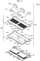
- Fig. 11 is a perspective view illustrating one of cell units 100T of Figs. 8 to 10 and another cell unit 100T (configurations excluding a metal-supported cell assembly 101) located below the one cell unit 100T in a disassembled state.
- Fig. 12 is a perspective view illustrating the metal-supported cell assembly 101 of Fig. 11 in a disassembled state.
- Fig. 13 is a side view illustrating a cross section of the metal-supported cell assembly 101 of Fig. 11 .
- Fig. 14 is a perspective view illustrating a separator 102 of Fig. 11 from the cathode side (illustrating the separator 102 as viewed from the upper side as in Fig. 11 ).
- Fig. 15 is a perspective view illustrating a portion (region 15 in Fig. 14 ) of the separator 102 of Fig. 14 .
- Fig. 16 is a perspective view illustrating the separator 102 of Fig.
- Fig. 17 is a perspective view illustrating a portion (region 17 in Fig. 16 ) of the separator 102 of Fig. 16 .
- Fig. 18 is a cross-sectional view partially illustrating a state where the metal-supported cell assemblies 101, the separators 102, and current collection assisting layers 103 of Fig. 11 are stacked.
- the fuel cell 100 is formed by sandwiching the cell stack assembly 100M between the external manifold 113 configured to supply gas from the outside and a cover 115 configured to protect the cell stack assembly 100M from the upper and lower sides.
- the cell stack assembly 100M is formed by sandwiching a pair of stacks 100S between one upper end plate 109 and a pair of the lower end plates 108 from the upper and lower sides and covering the stacks 100S with an air shelter 112 configured to seal a cathode gas CG.
- each stack 100S is formed by stacking the upper module unit 100P, the multiple middle module units 100Q, and the lower module unit 100R.
- the upper module unit 100P is formed by sandwiching the multiple cell units 100T stacked one on top of another between an upper current collection plate 106 configured to output power generated in the cell units 100T to the outside and a module end 105 corresponding to an end plate from the upper and lower sides.
- each middle module unit 100Q is formed by sandwiching the multiple cell units 100T stacked one on top of another between the paired module ends 105 from the upper and lower sides.
- the lower module unit 100R is formed by sandwiching the multiple cell units 100T stacked one on top of another between the module end 105 and a lower current collection plate 107 from the upper and lower sides.
- each cell unit 100T includes the metal-supported cell assembly 101 which is provided with power generation cells 101M configured to generate power by using supplied gas, the separator 102 which isolates the power generation cells 101M of the metal-supported cell assemblies 101 adjacent in the stacking direction Z from one another, the current collection assisting layers 103 which make surface pressure even while forming a space allowing gas to flow between the separator 102 and the power generation cells 101M of the metal-supported cell assembly 101, and sealing members 104 which seal edges of manifold portions of the metal-supported cell assembly 101 and the separator 102 and limit a flow of gas.
- the current collection assisting layers 103 and the sealing members 104 are arranged between the metal-supported cell assembly 101 and the separator 102 adjacent to each other in the stacking direction Z due to their structures.
- the current collection assisting layers 103 and the sealing members 104 are configured to be arranged between the joined bodies 100U (the metal-supported cell assembly 101 and the separator 102) adjacent to each other in the stacking direction Z.
- the current collection assisting layers 103 and the sealing members 104 are arranged between the metal-supported cell assembly 101 of one joined body 100U and the separator 102 of another joined body 100U adjacent to the one joined body 100U in the stacking direction Z.
- the metal-supported cell assembly 101 is provided with the power generation cells 101M configured to generate power by using the supplied gas.
- the metal-supported cell assembly 101 is formed of two metal-supported cells 101N arranged side by side in the long-side direction Y and a cell frame 101W holding peripheries of the metal-supported cells 101N.
- Each metal-supported cell 101N is formed of the power generation cell 101M and a support metal 101V supporting the power generation cell 101M from one side.
- each power generation cell 101M is formed by sandwiching an electrolyte 101S between an anode 101T and a cathode 101U.
- the anode 101T is a fuel electrode and causes an anode gas AG (for example, hydrogen) to react with oxide ions to generate oxide of the anode gas AG and take out electrons.
- the anode 101T is resistant to a reducing atmosphere, allows the anode gas AG to pass through, has high electrical conductivity, and has a catalyst effect of causing the anode gas AG to react with oxide ions.
- the anode 101T is formed in a rectangular shape larger than the electrolyte 101S.
- the anode 101T is made of cemented carbide in which metal such as nickel and oxide ion conductor such as yttria-stabilized zirconia are mixed.
- the anode 101T has a rectangular thin plate shape.
- the electrolyte 101S allows oxide ions to pass through from the cathode 101U to the anode 101T.
- the electrolyte 101S allows oxide ions to pass through but does not allow gas and electrons to pass through.
- the electrolyte 101S is formed in a rectangular shape.
- the electrolyte 101S is made of solid oxide ceramic such as stabilized zirconia containing yttrium, neodymium oxide, samarium, gadolinium, scandium, or the like in a solid solution state.
- the electrolyte 101S has a rectangular thin plate shape slightly larger than the anode 101T. As illustrated in Fig.
- an outer edge of the electrolyte 101S is bent toward the anode 101T and is in contact with a side surface of the anode 101T extending in the stacking direction Z.
- An end of the outer edge of the electrolyte 101S is in contact with the support metal 101V.
- the cathode 101U is an oxidant electrode and causes the cathode gas CG (for example, oxygen included in air) to react with electrons to convert oxygen molecules into oxide ions.
- the cathode 101U is resistant to an oxidizing atmosphere, allows the cathode gas CG to pass through, has high electrical conductivity, and has a catalyst effect of converting oxygen molecules into oxide ions.
- the cathode 101U is formed in a rectangular shape smaller than the electrolyte 101S.
- the cathode 101U is made of an oxide of lanthanum, strontium, manganese, cobalt, or the like. As illustrated in Figs.
- the cathode 101U has a rectangular thin plate shape.
- the cathode 101U faces the anode 101T with the electrolyte 101S therebetween. Since the outer edge of the electrolyte 101 S is bent toward the anode 101T, an outer edge of the cathode 101U does not come into contact with an outer edge of the anode 101T.
- the support metal 101V supports the power generation cell 101M from the anode 101T side.
- the support metal 101V has gas permeability, high electrical conductivity, and sufficient strength.
- the support metal 101V is formed in a rectangular shape sufficiently larger than the anode 101T.
- the support metal 101V is made of stainless steel or corrosion resistant alloy or corrosion resistant steel containing nickel and chrome.
- the cell frame 101W is provided with circular extending portions (a first extending portion 101p, a second extending portion 101q, and a third extending portion 101r) extending in a surface direction, respectively, from a right end, a center portion, and a left end of one side extending in the long-side direction Y.
- the cell frame 101W is provided with circular extending portions (a fourth extending portion 101s and a fifth extending portion 101t) extending in the surface direction, respectively, from two portions of another side extending in the long-side direction Y which are away from the center of the other side.
- the first, second, and third extending portions 101p, 101q, and 101r and the fourth and fifth extending portions 101s and 101t are arranged alternately in the longitudinal direction Y across the paired opening portions 101k.
- the cell frame 101W is provided with an anode side first flow-in port 101a, an anode side second flow-in port 101b, and an anode side third flow-in port 101c for passing (flow-in) of the anode gas AG respectively in the first extending portion 101p, the second extending portion 101q, and the third extending portion 101r.
- the cell frame 101W is provided with an anode side first flow-out port 101d and an anode side second flow-out port 101e for passing (flow-out) of the anode gas AG respectively in the fourth extending portion 101s and the fifth extending portion 101t.
- the anode side first flow-in port 101a, the anode side second flow-in port 101b, the anode side third flow-in port 101c, the anode side first flow-out port 101d, and the anode side second flow-out port 101e of the anode gas AG are so-called manifold.
- the cell frame 101W is provided with a cathode side first flow-in port 101f for passing (flow-in) of the cathode gas CG in a space between the first extending portion 101p and the second extending portion 101q.
- the cell frame 101W is provided with a cathode side second flow-in port 101g for passing (flow-in) of the cathode gas CG in a space between the second extending portion 101q and the third extending portion 101r.
- the cell frame 101W is provided with a cathode side first flow-out port 101h for passing (flow-out) of the cathode gas CG on the right side of the fourth extending portion 101s in Fig. 12 .
- the cell frame 101W is provided with a cathode side second flow-out port 101i for passing (flow-out) of the cathode gas CG in a space between the fourth extending portion 101s and the fifth extending portion 101t.
- the cell frame 101W is provided with a cathode side third flow-out port 101j for passing (flow-out) of the cathode gas CG on the left side of the fifth extending portion 101t in Fig. 12 .
- the cathode side first flow-in port 101f, the cathode side second flow-in port 101g, the cathode side first flow-out port 101h, the cathode side second flow-out port 101i, and the cathode side third flow-out port 101j correspond to spaces between an outer peripheral surface of the cell frame 101W and an inner surface of the air shelter 112.
- the separator 102 is provided between the power generation cells 101M of the stacked metal-supported cell assemblies 101 and isolates the adjacent power generation cells 101M from one another.
- the separator 102 is arranged to face the metal-supported cell assembly 101.
- the separator 102 has the same outer shape as the metal-supported cell assembly 101.
- the separator 102 is made of metal and is insulated by using an insulator or coating except for regions facing the power generation cells 101M (flow passage portions 102L).
- the insulator is formed by, for example, attaching aluminum oxide to the separator 102.
- the flow passage portions 102L are provided side by side in the long-side direction Y to face the power generation cells 101M.
- each flow passage portion 102L is formed by arranging flow passages, extending in a direction (short-side direction X) of gas flow, side by side in a direction (long-side direction Y) orthogonal to the direction (short-side direction X) of gas flow.
- protrusion-shaped anode side projections 102y are provided at fixed intervals to protrude downward from a flat portion 102x being flat in a plane extending in the long-side direction Y and the short-side direction X.
- the anode side projections 102y extend in the direction (short-side direction X) of gas flow.
- the anode side projections 102y protrude downward from a lower end of the separator 102.
- protrusion-shaped cathode side projections 102z are provided at fixed intervals to protrude upward from the flat portion 102x.
- the cathode side projections 102z extend in the direction (short-side direction X) of gas flow.
- the cathode side projections 102z protrude upward from an upper end of the separator 102.
- the anode side projections 102y and the protrusion-shape cathode side projections 102z are provided alternately in the long-side direction Y with the flat portion 102x therebetween.
- the flow passage portions 102L are formed as flow passages of the anode gas AG.
- the anode gas AG flows from an anode side second flow-in port 102b and the like of the separator 102 illustrated in Fig. 16 into the flow passage portions 102L on the anode side through multiple grooves 102q illustrated in Figs. 16 and 17 .
- the separator 102 as illustrated in Figs.
- the multiple grooves 102q are formed to radially extend from an anode side first flow-in port 102a, the anode side second flow-in port 102b, and an anode side third flow-in port 102c toward the flow passage portions 102L on the anode side.
- gaps between the flow passage portions 102L and the metal-supported cell assembly 101 located above (left side in Fig. 18 ) the flow passage portions 102L are formed as flow passages of the cathode gas CG.
- the cathode gas CG flows from a cathode side first flow-in port 102f and a cathode side second flow-in port 102g of the separator 102 illustrated in Fig. 14 into the flow passage portions 102L on the cathode side by crossing an outer edge 102p of the separator 102 on the cathode side illustrated in Figs. 14 and 15 .
- the outer edge 102p on the cathode side is formed to be thinner than other portions.
- the anode side first flow-in port 102a, the anode side second flow-in port 102b, the anode side third flow-in port 102c, an anode side first flow-out port 102d, and an anode side second flow-out port 102e for passing of the anode gas AG are provided to be aligned relative to the metal-supported cell assembly 101 in the stacking direction Z.
- the cathode side first flow-in port 102f, the cathode side second flow-in port 102g, a cathode side first flow-out port 102h, a cathode side second flow-out port 102i, and a cathode side third flow-out port 102j for passing of the cathode gas CG are provided to be aligned relative to the metal-supported cell assembly 101 in the stacking direction Z.
- the cathode side first flow-in port 102f, the cathode side second flow-in port 102g, the cathode side first flow-out port 102h, the cathode side second flow-out port 102i, and the cathode side third flow-out port 102j of the cathode gas CG correspond to spaces between an outer peripheral surface of the separator 102 and the inner surface of the air shelter 112.
- each current collection assisting layer 103 makes the surface pressure even while forming a space allowing the gas to flow between the power generation cell 101M and the separator 102 and assists an electrical contact between the power generation cell 101M and the separator 102.
- the current collection assisting layer 103 is so-called expanded metal.
- the current collection assisting layer 103 is arranged between the power generation cell 101M and the flow passage portion 102L of the separator 102.
- the current collection assisting layer 103 has the same outer shape as the power generation cell 101M.
- the current collection assisting layer 103 has a metal mesh shape provided with openings of a rhombic shape or the like arranged in a lattice pattern.
- the sealing members 104 partially seal the gap between the metal-supported cell assembly 101 and the separator 102 and limit the flow of gas.
- the sealing members 104 have functions of a spacer and a seal and are so-called gaskets.
- the sealing members 104 prevent the anode gas AG from flowing from the anode side flow-in ports (for example, the anode side first flow-in port 102a) and the anode side flow-out ports (for example, the anode side first flow-out port 102d) of the separator 102 toward the flow passages of the separator 102 on the cathode side and mixing into the flow passages.
- the sealing members 104 are formed in a ring shape.
- the sealing members 104 are joined to inner peripheral edges of the anode side flow-in ports (for example, the anode side first flow-in port 102a) and the anode side flow-out port (for example, the anode side first flow-out port 102d) leading to the surface of the separator 102 on the cathode side.
- the sealing members 104 are made of Thermiculite with heat resistance and sealing properties.
- each module end 105 is a plate which holds a lower end or an upper end of the multiple cell units 100T stacked one on top of another.
- the module end 105 is arranged at the lower end or the upper end of the multiple cell units 100T stacked one on top of another.
- the module end 105 has the same outer shape as the cell units 100T.
- the module end 105 is made of an electrically-conductive material which does not allow gas to pass through and is insulated by using an insulator or coating except for regions facing the power generation cells 101M and the other module end 105.
- the insulator is formed by, for example, attaching aluminum oxide to the module end 105.
- an anode side first flow-in port 105a, an anode side second flow-in port 105b, an anode side third flow-in port 105c, an anode side first flow-out port 105d, and an anode side second flow-out port 105e for passing of the anode gas AG are provided to be aligned relative to the cell units 100T in the stacking direction Z.
- a cathode side first flow-in port 105f, a cathode side second flow-in port 105g, a cathode side first flow-out port 105h, a cathode side second flow-out port 105i, and a cathode side third flow-out port 105j for passing of the cathode gas CG are provided to be aligned relative to the cell units 100T in the stacking direction Z.
- the cathode side first flow-in port 105f, the cathode side second flow-in port 105g, the cathode side first flow-out port 105h, the cathode side second flow-out port 105i, and the cathode side third flow-out port 105j corresponds to spaces between an outer peripheral surface of the module end 105 and the inner surface of the air shelter 112.
- the upper current collection plate 106 outputs power generated in the cell units 100T to the outside.
- the upper current collection plate 106 is arranged at an upper end of the upper module unit 100P.
- the upper current collection plate 106 has the same outer shape as the cell units 100T.
- the upper current collection plate 106 is provided with a terminal (not illustrated) to be connected to an external current carrying member.
- the upper current collection plate 106 is provided with multiple cylindrical recess portions 106a for arranging springs 110 on an upper surface.
- the upper current collection plate 106 is made of an electrically-conductive material which does not allow gas to pass through and is insulated by using an insulator or coating except for a portion of the terminal and regions facing the power generation cells 101M of the cell unit 100T.
- the insulator is formed by, for example, attaching aluminum oxide to the upper current collection plate 106.
- the lower current collection plate 107 outputs power generated in the cell units 100T to the outside.
- the lower current collection plate 107 is arranged at a lower end of the lower module unit 100R.
- the lower current collection plate 107 has the same outer shape as the upper current collection plate 106.
- the lower current collection plate 107 is provided with a terminal (not illustrated) to be connected to an external current carrying member.
- the lower current collection plate 107 is made of an electrically-conductive material which does not allow gas to pass through and is insulated by using an insulator or coating except for a portion of the terminal and regions facing the power generation cells 101M of the cell unit 100T.
- the insulator is formed by, for example, attaching aluminum oxide to the lower current collection plate 107.
- an anode side first flow-in port 107a, an anode side second flow-in port 107b, an anode side third flow-in port 107c, an anode side first flow-out port 107d, and an anode side second flow-out port 107e for passing of the anode gas AG are provided to be aligned relative to the cell units 100T in the stacking direction Z.
- a cathode side first flow-in port 107f, a cathode side second flow-in port 107g, a cathode side first flow-out port 107h, a cathode side second flow-out port 107i, and a cathode side third flow-out port 107j for passing of the cathode gas CG are provided to be aligned relative to the cell units 100T in the stacking direction Z.
- the cathode side first flow-in port 107f, the cathode side second flow-in port 107g, the cathode side first flow-out port 107h, the cathode side second flow-out port 107i, and the cathode side third flow-out port 107j correspond to spaces between an outer peripheral surface of the lower current collection plate 107 and the inner surface of the air shelter 112.
- the lower end plates 108 are provided as a pair and hold the paired stacks 100S from the lower side as illustrated in Figs. 2 , 3 , 5 and 6 (particularly Fig. 5 ).
- the lower end plates 108 are provided as a pair and are arranged at the lower ends of the stacks 100S side by side in the short-side direction X such that outer edges on the side from which the cathode gas CG flows out are opposed to each other.
- the lower end plates 108 have the same external shape as the cell units 100T excluding some portions. Both edges of each lower end plate 108 extending in the long-side direction Y are formed to extend linearly to form flow-in ports and discharge ports of the cathode gas CG. As illustrated in Figs.
- each lower end plate 108 is provided with paired screw holes 108m for screwing and fastening first fastening bolts 111 at both ends of an outer edge extending in the long-side direction Y on the side where the flow-in ports of the cathode gas CG are provided. As illustrated in Figs. 3 and 6 , each lower end plate 108 is provided with paired insertion holes 108n for inserting second fastening bolts 114 on the inner sides of the screw holes 108m in the long-side direction Y.
- the lower end plates 108 are formed to be sufficiently thicker than the cell units 100T.
- the lower end plates 108 are made of metal and upper surfaces to be in contact with the lower current collection plates 107 are insulated by using an insulator or coating. The insulator is formed by, for example, attaching aluminum oxide to the lower end plates 108.
- an anode side first flow-in port 108a As illustrated in Fig. 6 , in the lower end plate 108, an anode side first flow-in port 108a, an anode side second flow-in port 108b, an anode side third flow-in port 108c, an anode side first flow-out port 108d, and an anode side second flow-out port 108e for passing of the anode gas AG are provided to be aligned relative to the cell units 100T in the stacking direction Z.
- a cathode side first flow-in port 108f, a cathode side second flow-in port 108g, a cathode side first flow-out port 108h, a cathode side second flow-out port 108i, and a cathode side third flow-out port 108j for passing of the cathode gas CG are provided to be aligned relative to the cell units 100T in the stacking direction Z.
- the upper end plate 109 hold the paired stacks 100S from the upper side.
- the upper end plate 109 is arranged at upper ends of the stacks 100S.
- the upper end plate 109 has an outer shape obtained by integrating the lower end plates 108 in the short-side direction X to be left-right symmetric with respect to an axis extending the long-side direction Y.
- the upper end plate 109 is provided with paired insertion holes 109n for inserting the first fastening bolts 111 on both end of each of outer edges extending in the longitudinal direction Y on the sides where the flow-in ports of the cathode gas CG are provided.
- the upper end plate 109 is provided with no flow-in ports or discharge ports of gas.
- the upper end plate 109 is made of metal and a lower surface to be in contact with the upper current collection plates 106 is insulated by using an insulator or coating.
- the insulator is formed by, for example, attaching aluminum oxide to the upper end plate 109.
- the springs 110 apply elastic force to the paired stacks 100S.
- the springs 110 are arranged between the upper end plate 109 and the multiple recess portions 106a in the upper current collection plates 106.
- the springs 110 are helical metal springs with creep resistance.
- the springs 110 may be so-called leaf springs.
- the first fastening bolts 111 applies fastening force to the paired stacks 100S on the sides where the flow-in ports of the cathode gas CG are provided.
- first fastening bolts 111 are provided and inserted into the insertion holes 109n provided in four portions of the upper end plate 109 to be screwed and fastened to the screw holes 108m provided in two portions of each of the paired lower end plates 108.
- the first fastening bolts 111 apply fastening force to the paired stacks 100S arranged between the upper end plate 109 and the pair of lower end plates 108, on the sides where the flow-in ports of the cathode gas CG are provided.
- the air shelter 112 forms the flow passages of the cathode gas CG between itself and the pair of stacks 100S.
- the air shelter 112 covers the paired stacks 100S sandwiched between the pair of lower end plates 108 and the upper end plate 109, from above.
- the air shelter 112 forms the flow-in ports and the flow-out ports of the cathode gas CG for the components of the stacks 100S, by using gap portions between the inner surface of the air shelter 112 and side surfaces of the stacks 100S.
- the air shelter 112 is formed in a box shape and the entire lower portion and part of the side portion are opened.
- the air shelter 112 is made of metal and the inner surface is insulated by using an insulator or coating.
- the insulator is formed by, for example, attaching aluminum oxide to the air shelter 112.
- the external manifold 113 supplies gas from the outside to the multiple cell units 100T.
- the external manifold 113 is arranged below the cell stack assembly 100M.
- the external manifold 113 has an outer shape obtained by simplifying the shape of the lower end plates 108.
- the external manifold 113 is provided with screw holes 113m for screwing and fastening the second fastening bolts 114 on outer edges extending in the long-side direction Y on the side where the flow-in ports of the cathode gas CG are provided.
- the external manifold 113 is formed to be sufficiently thicker than the lower end plates 108.
- the external manifold 113 is made of metal.
- anode side first flow-in ports 113a As illustrated in Fig. 5 , in the external manifold 113, anode side first flow-in ports 113a, anode side second flow-in ports 113b, anode side third flow-in ports 113c, anode side first flow-out ports 113d, and anode side second flow-out ports 113e for passing of the anode gas AG are provided to be aligned relative to the cell units 100T in the stacking direction Z.
- cathode side first flow-in ports 113f, cathode side second flow-in ports 113g, cathode side first flow-out ports 113h, cathode side second flow-out ports 113i, and cathode side third flow-out ports 113j are provided to be aligned relative to the cell units 100T for passing of the cathode gas CG in the stacking direction Z.
- two cathode side first flow-in ports 113f, two cathode side second flow-in ports 113g, two cathode side first flow-out ports 113h, two cathode side second flow-out ports 113i, and two cathode side third flow-out ports 113j are provided in the short-side direction X to be left-right symmetric with respect to an axis extending the long-side direction Y.
- the second fastening bolts 114 apply fastening force to the paired lower end plates 108, on the sides where the flow-in ports of the cathode gas CG are provided.
- second fastening bolts 114 are provided and inserted into the insertion holes 108n provided in two portions of each of the paired lower end plates 108 to be screwed and fastened to the screw holes 113m provided in four portions of the external manifold 113.
- the second fastening bolts 114 apply fastening force to the paired lower end plates 108, on the sides where the flow-in ports of the cathode gas CG are provided.
- the cover 115 covers the cell stack assembly 100M to protect it.
- the cover 115 and the external manifold 113 sandwich the cell stack assembly 100M from the upper and lower sides.
- the cover 115 has a box shape and a lower portion thereof is opened.
- the cover 115 is made of metal and an inner surface is insulated by an insulator.
- Fig. 19A is a perspective view schematically illustrating flows of the anode gas AG and the cathode gas CG in the fuel cell 100.
- Fig. 19B is a perspective view schematically illustrating flows (one side) of the cathode gas CG in the fuel cell 100.
- Fig. 19C is a perspective view schematically illustrating flows (one side) of the anode gas AG in the fuel cell 100.
- the anode gas AG passes through the flow-in ports of the external manifold 113, the lower end plate 108, the module ends 105, the separators 102, and the metal-supported cell assemblies 101 and is supplied to the anodes 101T of the power generation cells 101M.
- the anode gas AG is supplied from the external manifold 113 to the upper current collection plate 106 being the terminal end while being distributed to the anode side flow passages provided in the gaps between the separators 102 and the metal-supported cell assemblies 101 alternately stacked one on top of another. Thereafter, the anode gas AG reacts in the power generation cells 101M, passes through the flow-out ports of the aforementioned components, and is discharged in a state of exhaust gas.
- the anode gas AG is supplied to the flow passage portions 102L while being isolated from the cathode gas CG such that a path of the anode gas AG intersects a path of the cathode gas CG.
- the anode gas AG passes through the anode side first flow-in port 102a, the anode side second flow-in port 102b, and the anode side third flow-in port 102c of the separator 102 located on the lower side in Fig.
- the cathode gas CG passes through the flow-in ports of the external manifold 113, the lower end plate 108, the module ends 105, the separators 102, and the metal-supported cell assemblies 101 and is supplied to the cathodes 101U of the power generation cells 101M.
- the cathode gas CG is supplied from the external manifold 113 to the upper current collection plate 106 being the terminal end while being distributed to the cathode side flow passages provided in the gaps between the metal-supported cell assemblies 101 and the separators 102 alternately stacked one on top of another.
- the cathode gas CG reacts in the power generation cells 101M, passes through the flow-out ports of the aforementioned components, and is discharged in the state of exhaust gas.
- the flow-in ports and the flow-out ports of the cathode gas CG in the aforementioned components are formed by the gaps between the outer peripheral surfaces of the aforementioned components and the inner surface of the air shelter 112.
- the cathode gas CG passes through the cathode side first flow-in port 102f and the cathode side second flow-in port 102g of the separator 102 located on the lower side in Fig. 19B and flows into the flow passage portions 102L of the separator 102 to be supplied to the cathodes 101U of the power generation cells 101M in the metal-supported cell assembly 101.
- the cathode gas CG having reacted in the cathodes 101U flows out from the flow passage portions 102L of the separator 102 located on the lower side in the Fig.
- Fig. 20A is a schematic view illustrating the fuel cell 100 of the first embodiment and is a view illustrating a state of the fuel cell 100 before activation.
- Fig. 20B is a schematic view illustrating the fuel cell 100 of the first embodiment and is a view illustrating a state of the fuel cell 100 in rapid temperature rise.
- Fig. 20C is a schematic view illustrating the fuel cell 100 of the first embodiment and is a view illustrating a state of the fuel cell 100 in a steady operation.
- the paired stacks 100S and the paired lower end plates 108 do not elongate.
- the paired stacks 100S and the paired lower end plates 108 smoothly elongates inward in the short-side direction X.
- Such a configuration can be achieved because the fastening force applied to the stacks 100S between the upper end plate 109 and the multiple lower end plates 108 on the gas flow-in port 100x side is set to be greater than that on the gas flow-out port 100y side.
- the fastening force is relatively small on the gas flow-out ports 100y side because there are no first fastening bolts 111 and the like.
- the paired stacks 100S and the paired lower end plates 108 are stable in a returned state expanding outward in the short-side direction X.
- the temperature difference between the gas flow-out ports 100y and the gas flow-in ports 100x in the steady operation is sufficiently smaller than the temperature difference between the gas flow-out ports 100y and the gas flow-in ports 100x in the rapid temperature rise.
- the stack structure of the fuel cell 100 is a structure in which multiple stacked bodies (stacks 100S) formed by alternately stacking the power generation cells 101M and the separators 102 are fixed to the end plates (upper end plate 109 and lower end plates 108) by using fixing means (first fastening bolts 111), the power generation cells 101M each formed by sandwiching the electrolyte 101S between the fuel electrode (anode 101T) and the oxidant electrode (cathode 101U) and configured to generate power by using the supplied gas (anode gas AG and cathode gas CG), the separators 102 each having the flow passage portions 102L, the gas flow-in ports 100x, and the gas flow-out ports 100y formed therein, the flow passage portions 102L configured to supply the gas to the power generation cells 101M, the gas flow-in ports 100x allowing the gas to flow into the flow passage portions 102L, and the gas flow-out ports 100y allowing the gas to flow out from the flow passage portions 102L.
- the method of absorbing thermal deformation in a fuel cell stack includes forming the power generation cell 101M by sandwiching the electrolyte 101S between the fuel electrode (anode 101T) and the oxidant electrode (cathode 101U), forming the stacked body (stack 100S) by sandwiching the power generation cell 101M between the paired separators 102, forming multiple stack 100S rows by stacking the multiple stacks 100S, arranging the multiple stack 100S rows side by side while forming a space 100K between the multiple stack 100s rows, and absorbing the thermal deformation in the direction orthogonal to the stacking direction by using the space 100K between the stack 100S rows.
- the first thermal deformation absorbing portion configured to absorb the thermal deformation in the stacks 100S in the direction orthogonal to the stacking direction Z can sufficiently reduce deformation occurring in the stacked members (including the stacks 100S).
- the first thermal deformation absorbing portion preferably includes the space 100K formed between the stacks 100S arranged side by side.
- the space 100K is preferably formed by fixing the stacks 100S arranged side by side to the end plate (upper end plate 109 and lower end plates 108) such that the opposed surfaces of the stacks 100S are arranged away from each other.
- the fuel cell 100 includes the external manifold 113 having the flow ports configured to supply the gas to the power generation cells 101M, the external manifold 113 is arranged outside the end plate (upper end plate 109 and lower end plates 108), and the first thermal deformation absorbing portion is formed in the external manifold 113.
- the fuel cell 100 described above can include the external manifold 113 and sufficiently reduce the deformation occurring in the stacked members (including the stacks 100S).
- the fixing means for fixing the stacks 100S to the end plate preferably includes fastening members (first fastening bolts 111).
- the fixing means which can provide arbitrary fastening force can be implemented in a very simple configuration using the first fastening bolts 111.
- the first fastening bolts 111 configured to fix the stacks 100S to the end plate (upper end plate 109 and lower end plates 108) fix at least the outer peripheral portions of the stacks 100S arranged side by side to the end plate (upper end plate 109 and lower end plates 108) and the end plate (upper end plate 109 and lower end plates 108) includes the upper end plate and the lower end plates sandwiching the multiple stacks 100S.
- the fuel cell 100 described above can provide arbitrary fastening force in a very simple configuration using the end plates including the upper end plate and the lower end plates.
- the stacks 100S include the gas flow-in ports 100x and the gas flow-out ports 100y, the gas flow-in ports 100x are provided in the outer peripheral portions of the stacks 100S arranged side by side, and the gas flow-out ports 100y are provided in portions of the stacks 100S including the opposed surfaces.
- the fuel cell 100 can sufficiently reduce the deformation occurring in the stacked members.
- the opposed stacks 100S has a configuration in which the gas flow-out sides are located on the inner sides.
- a configuration in which the outer sides are fastened by bolts to make the fastening force on the outer sides greater than the fastening force on the inner sides can be easily achieved.
- means for applying fastening force on the outer sides becomes complex.
- the fuel cell 100 preferably includes a second thermal deformation absorbing portion (springs 110) provided between the end plate (upper end plate 109 and lower end plates 108) and the stacks 100S and configured to absorb the thermal deformation in the stacking direction Z.
- springs 110 provided between the end plate (upper end plate 109 and lower end plates 108) and the stacks 100S and configured to absorb the thermal deformation in the stacking direction Z.
- the second thermal deformation absorbing portion (springs 110) is preferably arranged to correspond to the gas flow-in ports 100x and the gas flow-out ports 100y of the stacks 100S.
- expansion and contraction of the springs 110 can absorb the deformation of the gas flow-in ports and the gas flow-out ports where expansion and contraction due to temperature change tend to occur. Accordingly, the fuel cell 100 can sufficiently reduce the deformation occurring in the stacked members. Particularly, in the fuel cell 100 described above, even when the thermal conductivity or coefficient of linear thermal expansion greatly varies in the stacks 100S, resilience force of the springs 110 can prevent warping or like caused by this variation.
- the second thermal deformation absorbing portion (springs 110) preferably includes spring mechanisms and an amount of compression applied to the spring mechanisms in advance is greater than a difference between a portion where the amount of thermal expansion in the stacking direction Z is greatest and a portion where the amount of thermal expansion in the stacking direction Z is smallest.
- the second thermal deformation absorbing portion (springs 110) is preferably arranged to correspond to films of the electrolytes 101S arranged inside the stacks 100S and have an initial compression amount or spring constant smaller than the springs arranged at the gas flow-in ports 100x or the gas flow-out ports 100y.
- the fuel cell 100 since the resilience force of the springs 110 is always acting also in the case where the temperature is relatively low (for example, before the activation) for example, it is possible to avoid load loss in the portion where the thermal expansion is smallest and thereby prevent input of shear force and a decrease in power generation efficiency. Accordingly, the fuel cell 100 can sufficiently reduce the deformation occurring in the stacked members.
- the fastening force applied to the stacks 100S between the multiple lower end plates 108 and the upper end plate 109 on the gas flow-in port side is greater than that on the gas flow-out port side.
- the fastening force applied to the stacks 100S between the multiple lower end plates 108 and the upper end plate 109 on the gas flow-in port side is defined to be greater than that on the gas flow-out port side.
- the stacked members can smoothly elongate or shrink in the direction in which the deformation occurs, depending on changes in conditions (for example, an increase in temperature caused by flowing of gas). Accordingly, the fuel cell 100 can sufficiently reduce the deformation occurring in the stacked members.
- the spring constant of the springs 110 is set to be gas flow-in port > gas flow-out port to achieve the relationship in which the fastening force is gas flow-in port > gas flow-out port, irrespective of whether it is before, during, or after the activation.
- condition A a condition in which the fastening force between the lower end plates 108 and the manifold is gas flow-in port > gas flow-out port
- condition B a condition in which the fastening force between the lower end plates 108 and the upper end plate 109 is gas flow-in port > gas flow-out port
- the thermal conductivity or coefficient of linear thermal expansion greatly varies in the stacks 100S, the lower end plates 108, and the upper end plate 109, it is possible to prevent warping or generation of shearing force in a direction intersecting the stacking direction Z caused by this variation.
- the sealing members 104 with relatively low coefficient of linear thermal expansion can be prevented from being pulled by the other stacked members, it is possible to protect the sealing members 104 and maintain a gas sealing performance of the sealing members 104.
- the heated cathode gas CG to be supplied to the cathodes 101U is preferably supplied to the springs 110.
- the temperature of the springs 110 can be made close to the temperature of the stacks 100S. Moreover, when the temperature is high (for example, in the rapid temperature rise), the compression amount of the springs 110 increases and the spring constant of the springs 110 decreases and this can suppress an increase in the load generated by the springs 110. Specifically, an action of the spring compression amount increasing with an increase in the temperature of the springs 110 and an action of the spring constant decreasing with a decrease in the temperature of the springs 110 are simultaneously performed. Thus, the fuel cell 100 can sufficiently reduce the deformation occurring in the stacked members.
- a fuel cell 200 of the second embodiment is different from the aforementioned fuel cell 100 of the first embodiment in that an external manifold 213 is divided separately into gas flow-in portions and gas flow-out portions.
- Fig. 21A is a schematic view illustrating the fuel cell 200 of the second embodiment and is a view illustrating a state of the fuel cell 200 before the activation.
- Fig. 21B is a schematic view illustrating the fuel cell 200 of the second embodiment and is a view illustrating a state of the fuel cell 200 in the rapid temperature rise.
- Fig. 21C is a schematic view illustrating the fuel cell 200 of the second embodiment and is a view illustrating the state of the fuel cell 200 in the steady operation.
- a third fastening member (external manifold 213) is configured such that gas flow-in portions which allow the gas to flow into gas flow-in ports 200x and gas flow-out portions which allow the gas to flow out from gas flow-out ports 200y are divided in a direction intersecting the stacking direction Z.
- the external manifold 213 includes first base portions 213S corresponding to the gas flow-in ports 200x (two first base portions 213S are arranged opposite to each other on the outer sides in the short-side direction X intersecting the stacking direction Z), second base portions 213T corresponding to the gas flow-out ports 200y (two second base portions 213T are arranged opposite to each other on the inner sides in the short-side direction X intersecting the stacking direction Z), and a third base portion 213U corresponding to the center (one third base portion 213U is arranged at the center in the short-side direction X intersecting the stacking direction Z).
- the external manifold 213 is joined to the paired lower end plates 108.
- the first base portions 213S and the second base portions 213T are in contact with one another in the short-side direction X.
- the second base portions 213T and the third base portion 213U are out of contact with one another in the short-side direction X.
- the stacks 100S and the like smoothly elongate inward in the short-side direction X. Accordingly, the second base portions 213T following this elongation come out of contact with the first base portions 213S and come into contact with the third base portion 213U.
- the fuel cell 200 further includes the third fastening member (external manifold 213) in which the gas flow-in portions which allow the gas to flow into gas flow-in ports and the gas flow-out portions which allow the gas to flow out from the gas flow-out ports are divided in the direction intersecting the stacking direction Z and the external manifold 213 is joined to the lower end plates 108.
- third fastening member external manifold 213 in which the gas flow-in portions which allow the gas to flow into gas flow-in ports and the gas flow-out portions which allow the gas to flow out from the gas flow-out ports are divided in the direction intersecting the stacking direction Z and the external manifold 213 is joined to the lower end plates 108.
- the external manifold 213 can move in the planar direction about the gas flow-in portions and the gas flow-out ports, the shearing force can be canceled.
- the fuel cell 200 can sufficiently reduce the deformation occurring in the stacked members.
- a fuel cell 300 of the third embodiment is different from the aforementioned fuel cell 200 of the second embodiment in that the springs 110 are arranged also in portions overlapping the power generation cells 101M in the stacking direction Z.
- Fig. 22A is a schematic view illustrating the fuel cell 300 of the third embodiment and is a view illustrating a state of the fuel cell 300 before the activation.
- Fig. 22B is a schematic view illustrating the fuel cell 300 of the third embodiment and is a view illustrating a state of the fuel cell 300 in the rapid temperature rise.
- multiple springs 110 are arranged in a matrix pattern also in the portions overlapping the power generation cells 101M in the stacking direction Z.
- springs with lower resilience force than the springs 110 corresponding to the springs 110 in the first and second embodiments
- springs with lower resilience force than the springs 110 arranged at positions overlapping gas flow-in ports 300x and gas flow-out ports 300y in the stacking direction Z are selected.
- the springs 110 are arranged also in the portions overlapping the power generation cells 101M in the stacking direction Z and have smaller resilience force than the springs 110 at the positions overlapping the gas flow-in ports 300x and the gas flow-out ports 300y in the stacking direction Z.
- the surface pressure can be surely applied to the power generation cells 101M.
- the resilience force of the springs 110 is always acting on the power generation cells 101M irrespective of the temperature of the springs 110, it is possible to avoid load loss in a direction intersecting the stacking direction Z of the power generation cells 101M and thereby prevent input of shear force and a decrease in power generation efficiency. Accordingly, the fuel cell 300 can sufficiently reduce the deformation occurring in the stacked members.
- the fuel cell is described as a Solid Oxide Fuel Cell (SOFC).
- the fuel cell may be configured as a Polymer Electrolyte Membrane Fuel Cell (PEMFC), a Phosphoric Acid Fuel Cell (PAFC), or a Molten Carbonate Fuel Cell (MCFC).
- PEMFC Polymer Electrolyte Membrane Fuel Cell
- PAFC Phosphoric Acid Fuel Cell
- MCFC Molten Carbonate Fuel Cell
- SOFC Solid Oxide Fuel Cell
- the fuel cell may be formed by appropriately combining specifications of the first to third embodiments.
Applications Claiming Priority (1)
| Application Number | Priority Date | Filing Date | Title |
|---|---|---|---|
| PCT/JP2017/029208 WO2019030920A1 (fr) | 2017-08-10 | 2017-08-10 | Structure d'empilement pour pile à combustible et procédé d'absorption de déformation thermique pour empilement de piles à combustible |
Publications (2)
| Publication Number | Publication Date |
|---|---|
| EP3667794A1 true EP3667794A1 (fr) | 2020-06-17 |
| EP3667794A4 EP3667794A4 (fr) | 2020-08-05 |
Family
ID=65272180
Family Applications (1)
| Application Number | Title | Priority Date | Filing Date |
|---|---|---|---|
| EP17921285.7A Pending EP3667794A4 (fr) | 2017-08-10 | 2017-08-10 | Structure d'empilement pour pile à combustible et procédé d'absorption de déformation thermique pour empilement de piles à combustible |
Country Status (5)
| Country | Link |
|---|---|
| US (1) | US11495822B2 (fr) |
| EP (1) | EP3667794A4 (fr) |
| JP (1) | JP6927309B2 (fr) |
| CN (1) | CN111052474B (fr) |
| WO (1) | WO2019030920A1 (fr) |
Family Cites Families (14)
| Publication number | Priority date | Publication date | Assignee | Title |
|---|---|---|---|---|
| JPS6476682A (en) * | 1987-09-17 | 1989-03-22 | Mitsubishi Electric Corp | Fuel cell |
| JPH06333591A (ja) * | 1993-05-19 | 1994-12-02 | Sanyo Electric Co Ltd | 高電圧燃料電池システム |
| JPH10106610A (ja) * | 1996-09-30 | 1998-04-24 | Sanyo Electric Co Ltd | 燃料電池 |
| JP3388710B2 (ja) | 1999-03-16 | 2003-03-24 | 三菱電機株式会社 | 燃料電池 |
| US6692859B2 (en) * | 2001-05-09 | 2004-02-17 | Delphi Technologies, Inc. | Fuel and air supply base manifold for modular solid oxide fuel cells |
| US7001685B2 (en) * | 2002-06-24 | 2006-02-21 | Delphi Technologies, Inc. | Fuel cell stack assembly load frame with compression spring |
| JP2006108058A (ja) * | 2004-10-08 | 2006-04-20 | Toyota Motor Corp | 燃料電池スタックとその製造方法ならびに製造装置 |
| US20090004533A1 (en) | 2006-09-08 | 2009-01-01 | Honda Motor Co., Ltd. | Fuel cell stack |
| JP5236874B2 (ja) * | 2006-10-18 | 2013-07-17 | 本田技研工業株式会社 | 燃料電池スタック |
| US20080138684A1 (en) * | 2006-12-06 | 2008-06-12 | 3M Innovative Properties Company | Compact fuel cell stack with uniform depth flow fields |
| JP5684664B2 (ja) | 2011-07-13 | 2015-03-18 | 本田技研工業株式会社 | 燃料電池スタック |
| JP2013054918A (ja) * | 2011-09-05 | 2013-03-21 | Nissan Motor Co Ltd | 燃料電池スタック |
| US10096844B2 (en) * | 2013-10-03 | 2018-10-09 | Hamilton Sundstrand Corporation | Manifold for plural fuel cell stacks |
| CN107949946B (zh) | 2015-08-31 | 2022-03-25 | 斯凯瑞有限公司 | 模块化电化学电池组件、组、系统及制造方法 |
-
2017
- 2017-08-10 CN CN201780093819.9A patent/CN111052474B/zh active Active
- 2017-08-10 JP JP2019535559A patent/JP6927309B2/ja active Active
- 2017-08-10 US US16/637,132 patent/US11495822B2/en active Active
- 2017-08-10 EP EP17921285.7A patent/EP3667794A4/fr active Pending
- 2017-08-10 WO PCT/JP2017/029208 patent/WO2019030920A1/fr unknown
Also Published As
| Publication number | Publication date |
|---|---|
| WO2019030920A1 (fr) | 2019-02-14 |
| US20200251766A1 (en) | 2020-08-06 |
| US11495822B2 (en) | 2022-11-08 |
| JP6927309B2 (ja) | 2021-09-01 |
| CN111052474B (zh) | 2023-03-28 |
| CN111052474A (zh) | 2020-04-21 |
| JPWO2019030920A1 (ja) | 2020-03-26 |
| EP3667794A4 (fr) | 2020-08-05 |
Similar Documents
| Publication | Publication Date | Title |
|---|---|---|
| US10297854B2 (en) | Fuel cell stack | |
| EP2525429B1 (fr) | Pile à combustible | |
| CN108232270B (zh) | 燃料电池堆 | |
| EP3667786B1 (fr) | Structure d'unité de pile à combustible, et procédé de commande de structure d'unité de pile à combustible | |
| US11456477B2 (en) | Fuel cell stack | |
| US20080261104A1 (en) | Fuel cell | |
| EP3667794A1 (fr) | Structure d'empilement pour pile à combustible et procédé d'absorption de déformation thermique pour empilement de piles à combustible | |
| EP3667793A1 (fr) | Empilement de piles à combustible | |
| EP3699990B1 (fr) | Élément ressort, unité de pile à combustible et empilement de piles à combustible | |
| JP2019036445A (ja) | 燃料電池スタック | |
| JP2019036443A (ja) | 燃料電池スタックのセル構造および燃料電池セルのたわみ規制方法 | |
| KR20180039144A (ko) | 전기 화학 전지를 위한 다중 구성 요소 바이폴라 플레이트 | |
| JP6933039B2 (ja) | 燃料電池スタック | |
| EP3667788B1 (fr) | Structure de cellule pour pile à combustible et système de pile à combustible | |
| US11127958B2 (en) | Cell unit | |
| EP3686978A1 (fr) | Élément ressort, unité de pile à combustible, assemblage de piles à combustible, et procédé de fabrication dudit assemblage | |
| WO2019106766A1 (fr) | Empilement de piles à combustible |
Legal Events
| Date | Code | Title | Description |
|---|---|---|---|
| STAA | Information on the status of an ep patent application or granted ep patent |
Free format text: STATUS: THE INTERNATIONAL PUBLICATION HAS BEEN MADE |
|
| PUAI | Public reference made under article 153(3) epc to a published international application that has entered the european phase |
Free format text: ORIGINAL CODE: 0009012 |
|
| STAA | Information on the status of an ep patent application or granted ep patent |
Free format text: STATUS: REQUEST FOR EXAMINATION WAS MADE |
|
| 17P | Request for examination filed |
Effective date: 20200310 |
|
| AK | Designated contracting states |
Kind code of ref document: A1 Designated state(s): AL AT BE BG CH CY CZ DE DK EE ES FI FR GB GR HR HU IE IS IT LI LT LU LV MC MK MT NL NO PL PT RO RS SE SI SK SM TR |
|
| AX | Request for extension of the european patent |
Extension state: BA ME |
|
| A4 | Supplementary search report drawn up and despatched |
Effective date: 20200707 |
|
| RIC1 | Information provided on ipc code assigned before grant |
Ipc: H01M 8/248 20160101ALI20200701BHEP Ipc: H01M 8/249 20160101ALI20200701BHEP Ipc: H01M 8/247 20160101AFI20200701BHEP Ipc: H01M 8/12 20160101ALI20200701BHEP Ipc: H01M 8/124 20160101ALN20200701BHEP |
|
| DAV | Request for validation of the european patent (deleted) | ||
| DAX | Request for extension of the european patent (deleted) |