EP3667689A1 - Apparatus for interrupting an electric current - Google Patents
Apparatus for interrupting an electric current Download PDFInfo
- Publication number
- EP3667689A1 EP3667689A1 EP19216151.1A EP19216151A EP3667689A1 EP 3667689 A1 EP3667689 A1 EP 3667689A1 EP 19216151 A EP19216151 A EP 19216151A EP 3667689 A1 EP3667689 A1 EP 3667689A1
- Authority
- EP
- European Patent Office
- Prior art keywords
- connecting rods
- cutting device
- head
- articulation axis
- hinge pin
- Prior art date
- Legal status (The legal status is an assumption and is not a legal conclusion. Google has not performed a legal analysis and makes no representation as to the accuracy of the status listed.)
- Pending
Links
- 230000007246 mechanism Effects 0.000 claims abstract description 41
- 230000008878 coupling Effects 0.000 claims abstract description 4
- 238000010168 coupling process Methods 0.000 claims abstract description 4
- 238000005859 coupling reaction Methods 0.000 claims abstract description 4
- 238000005520 cutting process Methods 0.000 claims description 14
- 229910000851 Alloy steel Inorganic materials 0.000 claims description 7
- 230000002093 peripheral effect Effects 0.000 claims description 5
- VYZAMTAEIAYCRO-UHFFFAOYSA-N Chromium Chemical compound [Cr] VYZAMTAEIAYCRO-UHFFFAOYSA-N 0.000 claims description 4
- ZOKXTWBITQBERF-UHFFFAOYSA-N Molybdenum Chemical compound [Mo] ZOKXTWBITQBERF-UHFFFAOYSA-N 0.000 claims description 4
- 229910052804 chromium Inorganic materials 0.000 claims description 3
- 239000011651 chromium Substances 0.000 claims description 3
- 229910052750 molybdenum Inorganic materials 0.000 claims description 3
- 239000011733 molybdenum Substances 0.000 claims description 3
- 230000007480 spreading Effects 0.000 claims description 2
- 238000003892 spreading Methods 0.000 claims description 2
- 230000009471 action Effects 0.000 description 5
- 238000009825 accumulation Methods 0.000 description 3
- 238000006073 displacement reaction Methods 0.000 description 3
- 230000007935 neutral effect Effects 0.000 description 3
- 125000006850 spacer group Chemical group 0.000 description 3
- 241001272720 Medialuna californiensis Species 0.000 description 2
- 238000009826 distribution Methods 0.000 description 1
- 238000005516 engineering process Methods 0.000 description 1
- 238000010438 heat treatment Methods 0.000 description 1
- 238000002955 isolation Methods 0.000 description 1
- 238000004519 manufacturing process Methods 0.000 description 1
- 229910052751 metal Inorganic materials 0.000 description 1
- 239000002184 metal Substances 0.000 description 1
- 230000005405 multipole Effects 0.000 description 1
- 230000002028 premature Effects 0.000 description 1
- 230000004044 response Effects 0.000 description 1
Images


Classifications
-
- H—ELECTRICITY
- H01—ELECTRIC ELEMENTS
- H01H—ELECTRIC SWITCHES; RELAYS; SELECTORS; EMERGENCY PROTECTIVE DEVICES
- H01H3/00—Mechanisms for operating contacts
- H01H3/22—Power arrangements internal to the switch for operating the driving mechanism
- H01H3/30—Power arrangements internal to the switch for operating the driving mechanism using spring motor
- H01H3/3005—Charging means
- H01H3/3015—Charging means using cam devices
-
- H—ELECTRICITY
- H01—ELECTRIC ELEMENTS
- H01H—ELECTRIC SWITCHES; RELAYS; SELECTORS; EMERGENCY PROTECTIVE DEVICES
- H01H3/00—Mechanisms for operating contacts
- H01H3/22—Power arrangements internal to the switch for operating the driving mechanism
- H01H3/30—Power arrangements internal to the switch for operating the driving mechanism using spring motor
-
- H—ELECTRICITY
- H01—ELECTRIC ELEMENTS
- H01H—ELECTRIC SWITCHES; RELAYS; SELECTORS; EMERGENCY PROTECTIVE DEVICES
- H01H3/00—Mechanisms for operating contacts
- H01H3/32—Driving mechanisms, i.e. for transmitting driving force to the contacts
-
- H—ELECTRICITY
- H01—ELECTRIC ELEMENTS
- H01H—ELECTRIC SWITCHES; RELAYS; SELECTORS; EMERGENCY PROTECTIVE DEVICES
- H01H3/00—Mechanisms for operating contacts
- H01H3/02—Operating parts, i.e. for operating driving mechanism by a mechanical force external to the switch
- H01H3/04—Levers
-
- H—ELECTRICITY
- H01—ELECTRIC ELEMENTS
- H01H—ELECTRIC SWITCHES; RELAYS; SELECTORS; EMERGENCY PROTECTIVE DEVICES
- H01H3/00—Mechanisms for operating contacts
- H01H3/02—Operating parts, i.e. for operating driving mechanism by a mechanical force external to the switch
- H01H3/16—Operating parts, i.e. for operating driving mechanism by a mechanical force external to the switch adapted for actuation at a limit or other predetermined position in the path of a body, the relative movement of switch and body being primarily for a purpose other than the actuation of the switch, e.g. for a door switch, a limit switch, a floor-levelling switch of a lift
- H01H3/161—Operating parts, i.e. for operating driving mechanism by a mechanical force external to the switch adapted for actuation at a limit or other predetermined position in the path of a body, the relative movement of switch and body being primarily for a purpose other than the actuation of the switch, e.g. for a door switch, a limit switch, a floor-levelling switch of a lift for actuation by moving a closing member, e.g. door, cover or lid
-
- H—ELECTRICITY
- H01—ELECTRIC ELEMENTS
- H01H—ELECTRIC SWITCHES; RELAYS; SELECTORS; EMERGENCY PROTECTIVE DEVICES
- H01H3/00—Mechanisms for operating contacts
- H01H3/22—Power arrangements internal to the switch for operating the driving mechanism
- H01H3/30—Power arrangements internal to the switch for operating the driving mechanism using spring motor
- H01H3/3005—Charging means
- H01H3/3021—Charging means using unidirectional coupling
-
- H—ELECTRICITY
- H01—ELECTRIC ELEMENTS
- H01H—ELECTRIC SWITCHES; RELAYS; SELECTORS; EMERGENCY PROTECTIVE DEVICES
- H01H3/00—Mechanisms for operating contacts
- H01H3/22—Power arrangements internal to the switch for operating the driving mechanism
- H01H3/30—Power arrangements internal to the switch for operating the driving mechanism using spring motor
- H01H3/3052—Linear spring motors
-
- H—ELECTRICITY
- H01—ELECTRIC ELEMENTS
- H01H—ELECTRIC SWITCHES; RELAYS; SELECTORS; EMERGENCY PROTECTIVE DEVICES
- H01H3/00—Mechanisms for operating contacts
- H01H3/54—Mechanisms for coupling or uncoupling operating parts, driving mechanisms, or contacts
-
- H—ELECTRICITY
- H01—ELECTRIC ELEMENTS
- H01H—ELECTRIC SWITCHES; RELAYS; SELECTORS; EMERGENCY PROTECTIVE DEVICES
- H01H50/00—Details of electromagnetic relays
-
- H—ELECTRICITY
- H01—ELECTRIC ELEMENTS
- H01H—ELECTRIC SWITCHES; RELAYS; SELECTORS; EMERGENCY PROTECTIVE DEVICES
- H01H71/00—Details of the protective switches or relays covered by groups H01H73/00 - H01H83/00
- H01H71/10—Operating or release mechanisms
-
- H—ELECTRICITY
- H01—ELECTRIC ELEMENTS
- H01H—ELECTRIC SWITCHES; RELAYS; SELECTORS; EMERGENCY PROTECTIVE DEVICES
- H01H71/00—Details of the protective switches or relays covered by groups H01H73/00 - H01H83/00
- H01H71/10—Operating or release mechanisms
- H01H71/50—Manual reset mechanisms which may be also used for manual release
- H01H71/52—Manual reset mechanisms which may be also used for manual release actuated by lever
- H01H71/522—Manual reset mechanisms which may be also used for manual release actuated by lever comprising a cradle-mechanism
- H01H71/525—Manual reset mechanisms which may be also used for manual release actuated by lever comprising a cradle-mechanism comprising a toggle between cradle and contact arm and mechanism spring acting between handle and toggle knee
-
- H—ELECTRICITY
- H01—ELECTRIC ELEMENTS
- H01H—ELECTRIC SWITCHES; RELAYS; SELECTORS; EMERGENCY PROTECTIVE DEVICES
- H01H2235/00—Springs
- H01H2235/01—Spiral spring
Definitions
- the present invention relates to an apparatus for cutting off an electric current.
- the invention relates in particular to the field of electrical switching devices intended to interrupt an electric current, such as circuit breakers or switches.
- Cut-off devices with separable contacts include an energy accumulation switching mechanism which has the function of moving the electrical contacts of the device between an open and a closed state, for example in response to an action of a trip device or a user.
- a pivoting movable electrical contact is moved by a switching shaft mechanically coupled to a trigger hook via a linkage system.
- an energy accumulator comprising a spring is actuated to set in motion the connection system.
- the switching mechanism is therefore subject to numerous mechanical stresses each time the contacts are opened and closed.
- connection system comprises a first pair of connecting rods and a second pair of connecting rods, the first connecting rods being pivotally mounted on the release hook, the second connecting rods being pivotally mounted with a crank of the switching shaft, the first connecting rods being connected with the second connecting rods by means of a single hinge pin which forms a pivot connection between the first connecting rods and the second connecting rods.
- the articulation axis combines both the function of ensuring the pivot connection and maintaining the spacing of the pairs of connecting rods.
- the reliability of the switching mechanism is increased, in particular thanks to better durability of the connection system.
- the risk of accidental rupture of the pivot connection between the first connecting rods and the second connecting rods is reduced by the use of the connecting pin.
- the figure 1 represents a part of an electric breaking device 2 for interrupting an electric current, such as a circuit breaker or a contactor.
- the electrical current is cut off in the air and by means of separable electrical contacts.
- the device 2 is a low-voltage, high-current multipole circuit breaker.
- the device 2 comprises a fixed electrical contact 4 and a movable electrical contact 6 which, in certain examples, carries pivotally mounted contact fingers 8 arranged opposite the fixed contact 4.
- the contacts 4 and 6 are connected to connection terminals opposite of the appliance 2.
- the movable contact 6 is reversibly movable, for example by pivoting relative to a fixed frame of the device 2, between an open position and a closed position of the contacts, corresponding respectively to an electrically open state and an electrically closed state of the device 2.
- the axis of rotation of the movable contact 6 is here noted by the reference X6.
- the apparatus 2 also includes a switching mechanism 10 adapted to switch the contacts 4 and 6 between the open and closed state by displacement of the movable contact 6 between the open and closed positions.
- the mechanism 10 can be controlled by means of a trigger 12 of the device 2 and / or by a manual control member, such as a joystick or a push button.
- the device 2 is a multipolar device adapted to interrupt a polyphase electric current.
- the device 2 then comprises several poles, each of which is associated with an electrical phase and comprises a pair of contacts 4 and 6.
- the device 2 is unipolar.
- the mechanism 10 is a switching mechanism with accumulation of mechanical energy.
- the operating principle of a switching mechanism according to this technology is for example described in FR-2 985 600-B1 .
- the mechanism 10 includes in particular a switching shaft 20 coupled to the movable contact 6, here by means of a pivot link.
- the shaft 20 is movable in rotation about its longitudinal axis with respect to a fixed frame, or fixed support, of the device 2.
- the shaft 20 is common to all the poles and is mechanically coupled with each movable contact 6.
- the mechanism 10 also includes a trigger hook 40 and a connection system 22 coupling the switching shaft to the trigger hook.
- the connection system 22 is articulated by a pivot connection with a crank arm 24 carried by the shaft 20, as described below.
- the mechanism 10 also includes an opening pawl 26 associated with a latch 28, also called a “half moon”.
- the opening pawl 26 is pivotally mounted relative to the frame and cooperates with the trigger hook 40.
- a spring 29 is hung between, on the one hand, the shaft 20 and, on the other hand, an axis integral with the frame device 2.
- a closing lock 30, also called a “half moon” and an intermediate lever 31 cooperate mechanically with an actuator controlled by the release 12, such as an electromechanical coil actuator, and / or with the manual control member.
- an actuator controlled by the release 12 such as an electromechanical coil actuator, and / or with the manual control member.
- the association between the trigger and the lever 31 is shown diagrammatically by rods, although in practice this mechanical cooperation can be carried out in a completely different manner.
- the latch 30 is also mechanically associated with a closing pawl 32 mounted to pivot relative to the frame.
- the mechanism 10 further comprises a mechanical energy accumulation device 34, comprising at least one spring.
- the device 34 stores mechanical energy when the spring is compressed and restores this mechanical energy by the relaxation of the spring.
- a drive mechanism 36 here comprising one or more articulated and / or pivotally connected connecting parts relative to the fixed frame, is mechanically coupled to the device 34.
- the drive mechanism 36 acts on the connection system 22 to strike it and drive it to a closed position. In doing so, by moving, the connection system 22 in turn drives the trigger hook 40.
- the trigger hook 40 is here pivotally mounted relative to the frame and is articulated by a pivot connection with the connection system 22.
- the pivoting and rotational movements of the elements of the mechanism 10 take place around axes of rotation which are fixed relative to the frame and which extend parallel to each other, here in directions perpendicular to the plane of the image of the figure 1 and parallel to the X6 axis.
- the device 34 In a stable open position, illustrated by the figure 1 , the device 34 is armed, that is to say that the spring is compressed and stores energy.
- the latch 30 maintains the closing pawl 32 in a first position.
- the closing latch 30 is tilted, for example on action of the trigger 12 or of the push button, which releases the closing pawl 32.
- the movement of the closing pawl 32 actuates the device 34 and the energy accumulated in the device 34 is released, by a movement of relaxation of the spring, which, via the drive mechanism 36, actuates the connection system 22, for example by striking it, so as to move the movable contact 6 via the shaft 20, until the movable contact 6 comes into contact with the fixed contact 4.
- connection system 22 continues to move towards its closed position until passing in front of a predefined alignment position, called “neutral”, driving the trigger hook 40 and the opening pawl 26 towards a stop position, in which the backward movement of the connecting system 22 is prevented.
- the mechanism 10 is then in a stable closed position.
- the locking between the opening pawl 26 and the latch 28 is broken, for example by moving the lever 31 by means of the actuator 12 or by manual action directly on the latch 28.
- the pawl opening 26 pivots, which releases the stop of the trigger hook 40.
- connection system 22 is then no longer held in abutment by the hook 40 and can return to its initial position under the action of the restoring force exerted by the spring 29. Once this the connection system 22 has returned behind the neutral position, the contact 6 is driven to its open position. The mechanism 10 has returned to the stable open position.
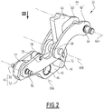
- FIG 2 and the figure 3 represent examples of the connection system 22 in accordance with embodiments of the invention.
- connection system 22 comprises a first pair of connecting rods 42 and a second pair of connecting rods 44 hinged together and on which the pivot articulation connections are formed with the trigger hook 40 and the shaft 20.
- the trigger hook 40 also carries an orifice 46 serving to receive a pivot connection with the frame and a stop 48 projecting here on either side of the trigger hook 40.
- the hook trigger 40 has an essentially flat shape.
- the stop 48 blocks the first pair of connecting rods 42 so as to lock the position of the connection system 22.
- the stop 48 forces the first pair of connecting rods 42 to move away under the action of the spring 29, so as to bring the connecting system 22 to the open position.
- the first pair 42 of connecting rods comprises two similar or identical connecting rods 50 and 52 and arranged parallel opposite one another.
- the connecting rods 50 and 52 have a planar shape.
- the connecting rods 50 and 52 are, on a first end, here a lower end, each pivotally mounted on the trigger hook 40, and more precisely, on a distal end 54 of the trigger hook 40.
- This pivot connection is here formed by means of a rigid axis 56, such as a journal, which extends perpendicular to the connecting rods 50 and 52.
- the reference X56 designates the axis of rotation associated with this pivot connection.
- the X56 axis is here parallel to the X6 axis.
- connection system 22 may also include a ring 58 mounted between the connecting rods 50 and 52 on a spacer 59 which secures the connecting rods 50 and 52 to each other.
- the spacer 59 here extends parallel to the axis X56.
- the spacer 59 and the ring 58 are struck by the drive mechanism 36 when the energy is released by the device 34.
- the neutral position of the connecting system 22 corresponds to the position of alignment of the pairs of connecting rods 42 and 44 between them along the same straight line, the pairs of connecting rods 42 being bent relative to the pairs of connecting rods 44 in the other positions.
- the second pair 44 of connecting rods comprises two similar or identical connecting rods 60 and 62 and arranged parallel opposite one another.
- the connecting rods 60 and 62 have a planar shape.
- each of the second connecting rods 60 and 62 has a shape curved in an arc of a circle, which improves the distribution of mechanical stresses and increases the mechanical endurance of the system 22.
- the connecting rods 60 and 62 are, on a first end, here an upper end, adapted to be pivotally mounted on the shaft 20, and more precisely, on an arm of the crank 24, here in an orifice formed in this arm of the crank 24.
- This pivot link is formed by means of a rigid axis 64, which extends perpendicular to the connecting rods 60 and 62, preferably by projecting with respect to the external lateral faces of the connecting rods 60 and 62.
- the reference X64 designates the axis of rotation associated with this pivot link.
- the X64 axis is here parallel to the X56 axis.
- the rigid axis 64 is placed on said first end of the connecting rods 60 and 62.
- the rigid axis 64 is fixedly secured to the connecting rods 60 and 62. In other words, the rigid axis 64 remains stationary relative to the connecting rods 60 and 62.
- the connecting rods 60 and 62 forming the second pair of connecting rods 44 are kept at a distance from one another in the direction X64 so as to allow the passage of one end 66 of the trigger hook 40 between the connecting rods 60 and 62.
- This end 66 forms a protruding hooking portion which cooperates with the opening pawl 26, for example by coming into abutment against the opening pawl 26 in the closed position.
- the connecting rods 50 and 52 are connected with the connecting rods 60 and 62 by means of a single hinge pin 68 which forms a pivot connection between the connecting rods 50 and 52 of the first pair 42 and the connecting rods 60 and 62 of the second pair 44.
- the reference X68 designates a straight line giving the axis of rotation associated with this pivot link.
- the axis of articulation 68 extends along this axis X68, which is named “direction X68” in the following to avoid any confusion with the axis of articulation 68.
- the connecting rods 60 and 62 are arranged on either side of the connecting rods 50 and 52 and are in contact with the connecting rods 50 and 52 over part of their length.
- the connecting rod 50 is adjacent to the connecting rod 60 and the connecting rod 52 is adjacent to the connecting rod 62.
- the pivot link formed by the hinge pin 68 is formed on the other end of each of the connecting rods 50, 52, 60 and 62, that is to say formed on the second end of the connecting rods 50 and 52 and on the second end of the connecting rods 60 and 62.
- the second end of each connecting rod is located opposite the first end of said connecting rod.
- the connecting rods 60 and 62 are, at their second end, connected to each other only by the axis 68. In other words, to maintain a constant spacing between the pairs of connecting rods 40 and 42, it is not necessary to add a fixed axis connecting the second ends of the connecting rods 60 and 62.
- the pivot link formed by the articulation axis 68 is located on the lower end of the connecting rods 60 and 62 and on the upper end of the connecting rods 50 and 52.
- the articulation is therefore formed essentially in the middle of the connection system 22.
- the hinge pin 68 comprises an elongated body, preferably cylindrical.
- the axis of articulation 68 has here a symmetry of revolution around the direction X68. Other forms are however possible.
- the connecting rods 50, 52, 60 and 62 comprise, on their corresponding ends, a through orifice which allows the body of the hinge pin 68 to pass.
- each of the ends of the hinge pin 68 comprises a head 70 and 72 formed integrally with the body of the hinge pin 68.
- the head 70 emerges from the side of the outer face of the connecting rod 60 and the head 72 emerges from the side of the outer face of the connecting rod 62.
- each head 70 and 72 is less than or equal to 5mm, preferably between 2mm and 3mm.
- Each head 70 and 72 has an extra width forming a retaining portion to prevent the rods 50 and 52 of the first pair 42 and the rods 60 and 62 of the second pair from being spaced apart from each other, that is to say say a spacing in direction X68.
- each head 70, 72 is wider than the body of the hinge pin 68.
- each head 70, 72 is greater than the diameter of the body of the articulation axis 68, for example at least 1.1 times greater than the diameter of the body of the hinge pin 68.
- the articulation axis 68 makes it possible to maintain a constant spacing between the connecting rods 50 and 52 and also between the connecting rods 60 and 62 even during the displacement of the connection system 22.
- the resistance to lateral tearing of a connecting rod in the direction X68 relative to the other connecting rods at the level of the articulation axis 68 is greater than or equal to 800 daN.
- the largest width of the head 70, 72 is between 9mm and 10mm, preferably between 9.6mm and 9.8mm.
- the radius R1 is between 4.5mm and 5mm and the radius R2 is between 3mm and 5mm.
- each head 70 and 72 has a conical shape, the base of which, in contact with the body of the hinge pin 68, has a radius R2 strictly less than the radius R1 measured at the top of the head 70, 72.
- the heads 70 and 72 are identical.
- each of the connecting rods 50 and 52 is mounted on a first zone of the articulation axis 68 having a first diameter D1 and each of the connecting rods 60 and 62 being mounted on a second zone of the articulation axis 68 having a second diameter D2 different from the first diameter D1.
- the diameter D1 is greater than the diameter D2.
- the body of the hinge pin 68 here comprises at least two zones of diameter D1 and at least two zones of diameter D2.
- the diameter D1 is equal to 9.5mm and the diameter D2 is equal to 9mm.
- zones of different dimensions form zones for receiving the rods which prevent the rods from sliding along the articulation axis 68 during the displacement of the connection system 22.
- the widening of the diameter between the second zone and the first zone prevents the connecting rods 60 and 62 from sliding towards the center of the articulation axis 68. This contributes to the stability of the connection system 22 and increases the pull-out resistance.
- the articulation axis 68 can preferably rotate freely around the direction X68 relative to the connecting rods 50, 52, 60 and 62.
- the hinge pin 68 is mounted in the connection system 22 with a radial clearance with the connecting rods 50, 52, 60 and 62 less than or equal to 0.1 mm and greater than 0mm.
- the radial clearance is here measured perpendicular to the direction X68.
- the radial clearance is chosen at each of the reception zones as a function of the diameter of the through hole of the corresponding rod 50, 52, 60 and 62.
- the connecting rods of the same pair of connecting rods 42, 44 have such a through hole having the same diameter.
- the hinge pin 68 is formed by a single piece.
- the hinge pin 68 is made of metal.
- the hinge pin 68 is made of a steel alloy, and more preferably of a steel alloy with chromium and molybdenum.
- this steel alloy has previously undergone a heat treatment in the mass to obtain a hardness of between 340 and 400 on the Vickers HV30 scale.
- the mechanical strength of the hinge pin 68 are improved, which increases the endurance of the connecting system 22 and reduces the risk of premature rupture, while providing the hinge pin 68 with sufficient rigidity to do not generate unexpected deformations of the pairs of connecting rods 42, 44 between them.
- the hinge pin 68 comprises a peripheral groove 74 formed at the base of each head 70 and 72, preferably arranged concentrically with the direction X68 and formed flush with the face of the connecting rod 60, 62 from which the head 70 or 72 emerges.
- the groove 74 makes it easier to obtain an axial clearance in the direction X68 between the articulation axis 68 and the connecting rods 50, 52, 60 and 62 with a desired value.
- the depth of the groove 74 measured perpendicular to the direction X68, is between 0.2mm and 0.6mm and, preferably, equal to 0.4mm.
- the reliability of the switching mechanism 10 is increased, in particular thanks to a better durability of the connection system 22.
- the risk of accidental rupture of the pivot link between the connecting rods 50, 52, 60 and 62 is reduced, while allowing a pivoting movement of the pair of connecting rods relative to the pair of connecting rods 44 necessary for the operation of the mechanism 10.
- the hinge pin 68 combines both the function of ensuring the pivot connection and maintaining the spacing of the pairs of connecting rods 42, 44.
- connection system 22 allows the connection system 22 to have a shape which makes it compatible with existing switching mechanisms, which makes it possible to use it in many ranges of devices. switching without the need to completely modify the architecture of the switching mechanisms of these devices.
- the better mechanical strength thus makes it possible to obtain a higher endurance of the mechanism 10.
- the device 2 is therefore capable of withstanding a higher number of mechanical opening and closing cycles during its lifetime.
- the device 2 can thus be advantageously used in critical applications requiring high reliability and in which it is likely to be frequently used, for example data centers or renewable energy production systems.
Abstract
Cet appareil de coupure (2) d'un courant électrique à contacts électriques séparables comporte un mécanisme (10) de commutation comprenant :un arbre de commutation (20) couplé à un contact électrique mobile (6) ;un crochet de déclenchement (40) monté pivotant sur un support fixe du mécanisme ;un système de liaison (22) couplant l'arbre de commutation au crochet de déclenchement.Le système de liaison (22) comporte une première paire (42) de bielles montées pivotantes sur le crochet de déclenchement et une deuxième paire (44) de bielles montées pivotantes avec une manivelle (24) de l'arbre de commutation. Les premières bielles sont connectées avec les deuxièmes bielles au moyen d'un unique axe d'articulation (68) qui forme une liaison pivot entre les premières bielles et les deuxièmes bielles.This device for breaking (2) an electric current with separable electric contacts comprises a switching mechanism (10) comprising: a switching shaft (20) coupled to a movable electric contact (6); a trigger hook (40) pivotally mounted on a fixed support of the mechanism; a link system (22) coupling the switching shaft to the trigger hook. The link system (22) comprises a first pair (42) of connecting rods pivotally mounted on the trigger hook and a second pair (44) of rods pivotally mounted with a crank (24) of the switching shaft. The first connecting rods are connected with the second connecting rods by means of a single hinge pin (68) which forms a pivot connection between the first connecting rods and the second connecting rods.
Description
La présente invention concerne un appareil de coupure d'un courant électrique.The present invention relates to an apparatus for cutting off an electric current.
L'invention se rapporte notamment au domaine des appareils de commutation électrique destinés à interrompre un courant électrique, tels que des disjoncteurs ou des interrupteurs.The invention relates in particular to the field of electrical switching devices intended to interrupt an electric current, such as circuit breakers or switches.
Les appareils de coupure à contacts séparables comportent un mécanisme de commutation à accumulation d'énergie qui a pour fonction de déplacer les contacts électriques de l'appareil entre un état ouvert et un état fermé, par exemple en réponse à une action d'un déclencheur ou d'un utilisateur.Cut-off devices with separable contacts include an energy accumulation switching mechanism which has the function of moving the electrical contacts of the device between an open and a closed state, for example in response to an action of a trip device or a user.
Un exemple d'un tel mécanisme est décrit dans
Par exemple, un contact électrique mobile pivotant est déplacé par un arbre de commutation couplé mécaniquement à un crochet de déclenchement par l'intermédiaire d'un système de liaison. Pour fermer les contacts, un accumulateur d'énergie comprenant un ressort est actionné pour mettre en mouvement le système de liaison.For example, a pivoting movable electrical contact is moved by a switching shaft mechanically coupled to a trigger hook via a linkage system. To close the contacts, an energy accumulator comprising a spring is actuated to set in motion the connection system.
Le mécanisme de commutation fait donc l'objet de nombreuses sollicitations mécaniques lors de chaque ouverture et fermeture des contacts.The switching mechanism is therefore subject to numerous mechanical stresses each time the contacts are opened and closed.
De tels mécanismes ont pendant longtemps donné satisfaction. Toutefois, dans certaines applications contemporaines, il est souhaitable de pouvoir disposer de mécanismes de commutation dont la durabilité est améliorée, par exemple pour augmenter le nombre de cycles d'ouverture et de fermeture admissibles pendant la durée de vie du produit.Such mechanisms have long been successful. However, in certain contemporary applications, it is desirable to be able to have switching mechanisms whose durability is improved, for example to increase the number of admissible opening and closing cycles during the lifetime of the product.
Il existe donc un besoin pour un appareil de coupure d'un courant électrique dont le mécanisme de commutation présente une fiabilité améliorée.There is therefore a need for an apparatus for cutting off an electric current, the switching mechanism of which has improved reliability.
A cet effet, un aspect de l'invention concerne un appareil de coupure d'un courant électrique comportant des contacts électriques fixe et mobile séparables et un mécanisme apte à commuter les contacts entre un état fermé et un état ouvert, le mécanisme comportant :
- un arbre de commutation couplé à un contact électrique mobile ;
- un crochet de déclenchement monté pivotant sur un support fixe du mécanisme ;
- un système de liaison couplant l'arbre de commutation au crochet de déclenchement.
- a switching shaft coupled to a movable electrical contact;
- a trigger hook pivotally mounted on a fixed support of the mechanism;
- a connection system coupling the switching shaft to the trigger hook.
Le système de liaison comporte une première paire de bielles et une deuxième paire de bielles, les premières bielles étant montées pivotantes sur le crochet de déclenchement, les deuxièmes bielles étant montées pivotantes avec une manivelle de l'arbre de commutation, les premières bielles étant connectées avec les deuxièmes bielles au moyen d'un unique axe d'articulation qui forme une liaison pivot entre les premières bielles et les deuxièmes bielles. L'axe d'articulation cumule à la fois la fonction d'assurer la liaison pivot et le maintien de l'écartement des paires de bielles.The connection system comprises a first pair of connecting rods and a second pair of connecting rods, the first connecting rods being pivotally mounted on the release hook, the second connecting rods being pivotally mounted with a crank of the switching shaft, the first connecting rods being connected with the second connecting rods by means of a single hinge pin which forms a pivot connection between the first connecting rods and the second connecting rods. The articulation axis combines both the function of ensuring the pivot connection and maintaining the spacing of the pairs of connecting rods.
Ainsi, la fiabilité du mécanisme de commutation est augmentée, notamment grâce à une meilleure durabilité du système de liaison. En particulier, le risque de rupture accidentelle de la liaison pivot entre les premières bielles et les deuxièmes bielles est réduit grâce à l'utilisation de l'axe de liaison.Thus, the reliability of the switching mechanism is increased, in particular thanks to better durability of the connection system. In particular, the risk of accidental rupture of the pivot connection between the first connecting rods and the second connecting rods is reduced by the use of the connecting pin.
Selon des aspects avantageux mais non obligatoires, un tel appareil peut incorporer une ou plusieurs des caractéristiques suivantes, prises isolément ou suivant toute combinaison techniquement admissible :
- Chacune des extrémités de l'axe d'articulation comporte une tête, chaque tête comportant une surlargeur formant une portion de retenue pour empêcher un écartement des premières bielles et deuxième bielles les unes par rapport aux autres.
- L'axe d'articulation comporte une gorge périphérique formée à la base de chaque tête.
- La profondeur de la gorge périphérique est comprise entre 0,2mm et 0,6mm et, de préférence, égale à 0,4mm.
- La hauteur de chaque tête est inférieure ou égale à 5mm, de préférence comprise entre 2mm et 3mm.
- La plus grande largeur de la tête est comprise entre 9mm et 10mm, de préférence comprise entre 9,6mm et 9,8mm.
- L'axe d'articulation est monté dans le système de liaison en présentant un jeu radial inférieur ou égal à 0,1mm avec les première et deuxième bielles.
- Chacune des premières bielles est montée sur une première zone de l'axe d'articulation présentant un premier diamètre, et chacune des deuxième bielles étant montée sur une deuxième zone de l'axe d'articulation présentant un deuxième diamètre différent du premier diamètre.
- L'axe d'articulation est réalisé en un alliage d'acier, par exemple en alliage d'acier avec du chrome et du molybdène.
- L'axe d'articulation est formé par une pièce monobloc.
- Chacune des deuxièmes bielles présente une forme recourbée en arc de cercle.
- Each of the ends of the articulation axis comprises a head, each head comprising an enlargement forming a retaining portion to prevent the first connecting rods and second connecting rods from spreading with respect to one another.
- The articulation axis has a peripheral groove formed at the base of each head.
- The depth of the peripheral groove is between 0.2mm and 0.6mm and preferably equal to 0.4mm.
- The height of each head is less than or equal to 5mm, preferably between 2mm and 3mm.
- The largest width of the head is between 9mm and 10mm, preferably between 9.6mm and 9.8mm.
- The articulation axis is mounted in the connection system with a radial clearance less than or equal to 0.1mm with the first and second connecting rods.
- Each of the first connecting rods is mounted on a first zone of the articulation axis having a first diameter, and each of the second connecting rods being mounted on a second zone of the articulation axis having a second diameter different from the first diameter.
- The hinge pin is made of a steel alloy, for example a steel alloy with chromium and molybdenum.
- The articulation axis is formed by a single piece.
- Each of the second connecting rods has a curved shape in an arc.
L'invention sera mieux comprise et d'autres avantages de celle-ci apparaîtront plus clairement à la lumière de la description qui va suivre d'un mode de réalisation d'un appareil électrique donnée uniquement à titre d'exemple et faite en référence aux dessins annexés, dans lesquels :
- [
Fig 1 ] lafigure 1 illustre schématiquement un appareil de coupure à contacts séparables, représenté selon un plan de coupe médian, comportant un mécanisme de commutation conforme à des modes de réalisation de l'invention ; - [
Fig 2 ] lafigure 2 illustre schématiquement, selon une vue en perspective isométrique, d'un système de liaison faisant partie du mécanisme de commutation de lafigure 1 ; - [
Fig 3 ] lafigure 3 illustre schématiquement le système de liaison de lafigure 2 selon une vue en élévation représentée par la flèche III ; - [
Fig 4 ] lafigure 4 illustre schématiquement un axe du système de liaison de lafigure 2 selon une vue en coupe longitudinale.
- [
Fig 1 ] thefigure 1 schematically illustrates a cut-off device with separable contacts, represented according to a median section plane, comprising a switching mechanism according to embodiments of the invention; - [
Fig 2 ] thefigure 2 schematically illustrates, in an isometric perspective view, of a connection system forming part of the switching mechanism of thefigure 1 ; - [
Fig 3 ] thefigure 3 schematically illustrates the linkage system of thefigure 2 according to an elevation view represented by arrow III; - [
Fig 4 ] thefigure 4 schematically illustrates an axis of the linkage system of thefigure 2 in a longitudinal section view.
La
Selon des exemples, l'appareil 2 est un disjoncteur multipolaire à basse tension et à forte intensité.According to examples, the
L'appareil 2 comporte un contact électrique fixe 4 et un contact électrique mobile 6 qui, dans certains exemples, porte des doigts de contact 8 montés pivotants disposés en regard du contact fixe 4. Les contacts 4 et 6 sont connectés à des bornes de raccordement électriques opposées de l'appareil 2.The
Le contact mobile 6 est réversiblement déplaçable, par exemple par pivotement par rapport à un bâti fixe de l'appareil 2, entre une position d'ouverture et une position de fermeture des contacts, correspondant respectivement à un état électriquement ouvert et un état électriquement fermé de l'appareil 2. L'axe de rotation du contact mobile 6 est ici noté par la référence X6.The movable contact 6 is reversibly movable, for example by pivoting relative to a fixed frame of the
L'appareil 2 comporte également un mécanisme 10 de commutation adapté pour commuter les contacts 4 et 6 entre l'état ouvert et fermé par déplacement du contact mobile 6 entre les positions ouverte et fermée.The
Par exemple, le mécanisme 10 est pilotable au moyen d'un déclencheur 12 de l'appareil 2 et/ou par un organe de commande manuel, tel qu'une manette ou un bouton poussoir.For example, the
Selon des modes de réalisation, l'appareil 2 est un appareil multipolaire adapté pour interrompre un courant électrique polyphasé. L'appareil 2 comporte alors plusieurs pôles, dont chacun est associé à une phase électrique et comporte une paire de contacts 4 et 6. En variante, l'appareil 2 est unipolaire.According to embodiments, the
Selon des modes de mise en oeuvre, le mécanisme 10 est un mécanisme de commutation à accumulation d'énergie mécanique. Le principe de fonctionnement d'un mécanisme de commutation selon cette technologie est par exemple décrit dans
Le mécanisme 10 comporte notamment un arbre de commutation 20 couplé au contact mobile 6, ici au moyen d'une liaison pivot. L'arbre 20 est mobile en rotation autour de son axe longitudinal par rapport à un bâti fixe, ou support fixe, de l'appareil 2.The
Dans le cas où l'appareil 2 comporte plusieurs pôles, l'arbre 20 est commun à tous les pôles et est couplé mécaniquement avec chaque contact mobile 6.In the case where the
Le mécanisme 10 comprend également un crochet de déclenchement 40 et un système de liaison 22 couplant l'arbre de commutation au crochet de déclenchement. Par exemple, le système de liaison 22 est articulé par une liaison pivot avec un bras de manivelle 24 porté par l'arbre 20, comme décrit ci-après.The
Le mécanisme 10 comporte aussi un cliquet d'ouverture 26 associé à un verrou 28, aussi nommé « demi-lune ».The
Le cliquet d'ouverture 26 est monté pivotant par rapport au bâti et coopère avec le crochet de déclenchement 40. Un ressort 29 est accroché entre, d'une part, l'arbre 20 et, d'autre part, un axe solidaire du bâti de l'appareil 2.The opening
Un verrou de fermeture 30, aussi nommé « demi-lune » et un levier 31 intermédiaire coopèrent mécaniquement avec un actionneur piloté par le déclencheur 12, tel qu'un actionneur électromécanique à bobine, et/ou avec l'organe de commande manuelle. Sur la
Le verrou 30 est également associé mécaniquement avec un cliquet de fermeture 32 monté pivotant par rapport au bâti.The
Le mécanisme 10 comporte en outre un dispositif d'accumulation d'énergie mécanique 34, comportant au moins un ressort. Par exemple, le dispositif 34 stocke de l'énergie mécanique lorsque le ressort est comprimé et restitue cette énergie mécanique par la détente du ressort.The
Un mécanisme d'entraînement 36, comportant ici une ou plusieurs pièces de liaison articulées et/ou montées pivotantes par rapport au bâti fixe, est couplé mécaniquement au dispositif 34. Le mécanisme d'entraînement 36 agit sur le système de liaison 22 pour le percuter et l'entraîner vers une position de fermeture. Ce faisant, en se déplaçant, le système de liaison 22 entraîne à son tour le crochet de déclenchement 40.A
Le crochet de déclenchement 40 est ici monté pivotant par rapport au bâti et est articulé par une liaison pivot avec le système de liaison 22.The
Pour faciliter la compréhension de la présente description, les autres composants de l'appareil 2 ne sont pas illustrés ni décrits en détail.To facilitate understanding of the present description, the other components of the
Dans les modes de réalisation illustrés, les mouvements de pivotement et de rotation des éléments du mécanisme 10 ont lieu autour d'axes de rotation qui sont fixes par rapport au bâti et qui s'étendent parallèlement entre eux, ici selon des directions perpendiculaires au plan de l'image de la
Des exemples de fonctionnement du mécanisme 10 sont maintenant brièvement décrits.Examples of operation of the
Dans une position stable d'ouverture, illustrée par la
Pour fermer les contacts 4 et 6, le verrou de fermeture 30 est basculé, par exemple sur action du déclencheur 12 ou du bouton poussoir, ce qui libère le cliquet de fermeture 32.To close the
Le déplacement du cliquet de fermeture 32 actionne le dispositif 34 et l'énergie accumulée dans le dispositif 34 est libérée, par un mouvement de détente du ressort, ce qui, par l'intermédiaire du mécanisme d'entraînement 36, actionne le système de liaison 22, par exemple en le percutant, de sorte à le déplacer le contact mobile 6 par l'intermédiaire de l'arbre 20, jusqu'à ce que le contact mobile 6 vienne en contact avec le contact fixe 4.The movement of the closing
Le système de liaison 22 continue à se déplacer vers sa position de fermeture jusqu'à passer en avant d'une position d'alignement prédéfinie, nommée « point mort », entraînant le crochet de déclenchement 40 et le cliquet d'ouverture 26 vers une position de butée, dans laquelle le retour en arrière du système de liaison 22 est empêché.The
Le mécanisme 10 est alors dans une position stable de fermeture.The
Pour rouvrir l'appareil 2, le verrouillage entre le cliquet d'ouverture 26 et le verrou 28 est rompu, par exemple en déplaçant le levier 31 au moyen de l'actionneur 12 ou par une action manuelle directement sur le verrou 28. Le cliquet d'ouverture 26 pivote, ce qui libère la butée du crochet de déclenchement 40.To reopen the
Le système de liaison 22 n'est alors plus maintenu en butée par le crochet 40 et peut revenir vers sa position initiale sous l'action de la force de rappel exercée par le ressort 29. Une fois que ce le système de liaison 22 est revenu derrière la position de point mort, le contact 6 est entraîné vers sa position d'ouverture. Le mécanisme 10 est revenu dans la position stable d'ouverture.The
La
Le système de liaison 22 comporte une première paire de bielles 42 et une deuxième paire de bielles 44 articulées entre elles et sur lesquelles sont formées les liaisons pivot d'articulation avec le crochet de déclenchement 40 et l'arbre 20.The
Dans l'exemple illustré, le crochet de déclenchement 40 porte également un orifice 46 servant à recevoir une liaison pivot avec le bâti et une butée 48 faisant ici saillie de part et d'autre du crochet de déclenchement 40. Par exemple, le crochet de déclenchement 40 présente une forme essentiellement plate.In the example illustrated, the
Selon des exemples, dans la position de fermeture du mécanisme 10 précédemment décrite, la butée 48 bloque la première paire de bielles 42 de manière à verrouiller la position du système de liaison 22. Lors du mouvement d'ouverture, la butée 48 force la première paire de bielles 42 à s'éloigner sous l'action du ressort 29, de sorte à ramener le système de liaison 22 vers la position d'ouverture.According to examples, in the closed position of the
La première paire 42 de bielles comporte deux bielles 50 et 52 semblables ou identiques et disposées parallèlement en regard l'une de l'autre. Selon des exemples, les bielles 50 et 52 présentent une forme plane.The
Les bielles 50 et 52 sont, sur une première extrémité, ici une extrémité inférieure, chacune montées pivotantes sur le crochet de déclenchement 40, et plus précisément, sur une extrémité distale 54 du crochet de déclenchement 40.The connecting
Cette liaison pivot est ici formée au moyen d'un axe rigide 56, tel qu'un tourillon, qui s'étend perpendiculairement aux bielles 50 et 52. La référence X56 désigne l'axe de rotation associé à cette liaison pivot. L'axe X56 est ici parallèle à l'axe X6.This pivot connection is here formed by means of a
Selon des exemples, le système de liaison 22 peut également comporter une bague 58 montée entre les bielles 50 et 52 sur une entretoise 59 qui solidarise les bielles 50 et 52 l'une à l'autre. L'entretoise 59 s'étend ici parallèlement à l'axe X56.According to examples, the
Par exemple, l'entretoise 59 et la bague 58 sont percutées par le mécanisme d'entraînement 36 lorsque l'énergie est libérée par le dispositif 34.For example, the
Dans l'exemple du mécanisme 10 décrit ci-dessus, la position de point mort du système de liaison 22 correspond à la position d'alignement des paires de bielles 42 et 44 entre elles le long d'une même droite, les paires de bielles 42 étant coudées par rapport aux paires de bielles 44 dans les autres positions.In the example of the
La deuxième paire 44 de bielles comporte deux bielles 60 et 62 semblables ou identiques et disposées parallèlement en regard l'une de l'autre. Selon des exemples, les bielles 60 et 62 présentent une forme plane.The
Selon des modes de réalisation optionnels mais néanmoins avantageux, chacune des deuxièmes bielles 60 et 62 présente une forme recourbée en arc de cercle, ce qui améliore la répartition des sollicitations mécaniques et augmente l'endurance mécanique du système 22.According to optional but nevertheless advantageous embodiments, each of the second connecting
Les bielles 60 et 62 sont, sur une première extrémité, ici une extrémité supérieure, adaptées pour être montées pivotantes sur l'arbre 20, et plus précisément, sur un bras de la manivelle 24, ici dans un orifice formé dans ce bras de la manivelle 24.The connecting
Cette liaison pivot est formée au moyen d'un axe rigide 64, qui s'étend perpendiculairement aux bielles 60 et 62, de préférence en faisant saillie par rapport aux faces latérales extérieures des bielles 60 et 62. La référence X64 désigne l'axe de rotation associé à cette liaison pivot. L'axe X64 est ici parallèle à l'axe X56. L'axe rigide 64 est placé sur ladite première extrémité des bielles 60 et 62.This pivot link is formed by means of a
Selon des exemples, l'axe rigide 64 est solidarisé fixement avec les bielles 60 et 62. En d'autres termes, l'axe rigide 64 reste immobile par rapport aux bielles 60 et 62.According to examples, the
Les bielles 60 et 62 formant la deuxième paire de bielles 44 sont maintenues à distance l'une de l'autre selon la direction X64 de manière à permettre le passage d'une extrémité 66 du crochet de déclenchement 40 entre les bielles 60 et 62.The connecting
Cette extrémité 66 forme une portion d'accrochage saillante qui coopère avec le cliquet d'ouverture 26, par exemple en venant en butée contre le cliquet d'ouverture 26 dans la position fermée.This
Les bielles 50 et 52 sont connectées avec les bielles 60 et 62 au moyen d'un unique axe d'articulation 68 qui forme une liaison pivot entre les bielles 50 et 52 de la première paire 42 et les bielles 60 et 62 de la deuxième paire 44. La référence X68 désigne une droite donnant l'axe de rotation associée à cette liaison pivot.The connecting
L'axe d'articulation 68 s'étend le long de cet axe X68, qui est nommé « direction X68 » dans ce qui suit pour éviter toute confusion avec l'axe d'articulation 68.The axis of
Selon des exemples, les bielles 60 et 62 sont disposées de part et d'autre des bielles 50 et 52 et sont en contact avec les bielles 50 et 52 sur une partie de leur longueur. La bielle 50 est adjacente à la bielle 60 et la bielle 52 est adjacente à la bielle 62.According to examples, the connecting
La liaison pivot formée par l'axe d'articulation 68 est formée sur l'autre extrémité de chacune des bielles 50, 52, 60 et 62, c'est-à-dire formée sur la deuxième extrémité des bielles 50 et 52 et sur la deuxième extrémité des bielles 60 et 62. En pratique, la deuxième extrémité de chaque bielle est située à l'opposé de la première extrémité de ladite bielle.The pivot link formed by the
Comme illustré par les figures, les bielles 60 et 62 sont, au niveau de leur deuxième extrémité, reliées entre elles uniquement par l'axe 68. En d'autres termes, pour maintenir un écartement constant entre les paires de bielles 40 et 42, il n'est pas nécessaire d'ajouter un axe fixe reliant les deuxièmes extrémités des bielles 60 et 62.As illustrated by the figures, the connecting
Ainsi, dans les exemples illustrés, la liaison pivot formée par l'axe d'articulation 68 est située sur l'extrémité inférieure des bielles 60 et 62 et sur l'extrémité supérieure des bielles 50 et 52. Dans ces exemples, l'articulation est donc formée essentiellement au milieu du système de liaison 22.Thus, in the examples illustrated, the pivot link formed by the
Comme illustré sur la
En pratique, les bielles 50, 52, 60 et 62 comprennent, sur leurs extrémités correspondantes, un orifice traversant qui permet le passage du corps de l'axe d'articulation 68.In practice, the connecting
De préférence, chacune des extrémités de l'axe d'articulation 68 comporte une tête 70 et 72 formée d'un seul tenant avec le corps de l'axe d'articulation 68.Preferably, each of the ends of the
Dans l'exemple illustré, la tête 70 émerge du côté de la face extérieure de la bielle 60 et la tête 72 émerge du côté de la face extérieure de la bielle 62.In the example illustrated, the
De façon préférentielle mais néanmoins optionnelle, la hauteur de chaque tête 70 et 72, notée « h », mesurée perpendiculairement à la face de la bielle 60 ou 62 depuis laquelle la tête émerge, est inférieure ou égale à 5mm, de préférence comprise entre 2mm et 3mm.Preferably but nonetheless optionally, the height of each
Chaque tête 70 et 72 comporte une surlargeur formant une portion de retenue pour empêcher un écartement des bielles 50 et 52 de la première paire 42 et des bielles 60 et 62 de la deuxième paire les unes par rapport aux autres, c'est-à-dire un écartement selon la direction X68.Each
En d'autres termes, chaque tête 70, 72 est plus large que le corps de l'axe d'articulation 68.In other words, each
Par exemple, dans le cas où l'axe d'articulation 68 est cylindrique, le diamètre de chaque tête 70, 72 est supérieur au diamètre du corps de l'axe d'articulation 68, par exemple au moins 1,1 fois supérieur au diamètre du corps de l'axe d'articulation 68.For example, in the case where the
L'axe d'articulation 68 permet de maintenir un écartement constant entre les bielles 50 et 52 et aussi entre les bielles 60 et 62 même pendant le déplacement du système de liaison 22.The
A titre d'exemple illustratif, la résistance à l'arrachement latéral d'une bielle selon la direction X68 par rapport aux autres bielles au niveau de l'axe d'articulation 68, exprimée par la force minimale nécessaire pour un tel arrachement, est supérieure ou égale à 800 daN.By way of illustrative example, the resistance to lateral tearing of a connecting rod in the direction X68 relative to the other connecting rods at the level of the
Selon des exemples, la plus grande largeur de la tête 70, 72, ici mesurée perpendiculairement à la direction X68, est comprise entre 9mm et 10mm, de préférence comprise entre 9,6mm et 9,8mm.According to examples, the largest width of the
Par exemple, le rayon R1 est compris entre 4,5mm et 5mm et le rayon R2 est compris entre 3mm et 5mm.For example, the radius R1 is between 4.5mm and 5mm and the radius R2 is between 3mm and 5mm.
Par exemple, chaque tête 70 et 72 présente une forme conique dont la base, en contact avec le corps de l'axe d'articulation 68, présente un rayon R2 strictement inférieur au rayon R1 mesuré au sommet de la tête 70, 72.For example, each
D'autres formes sont néanmoins possibles, par exemple une forme cylindrique de diamètre constant mais néanmoins supérieur au diamètre du corps de l'axe 68.Other shapes are nevertheless possible, for example a cylindrical shape of constant diameter but nevertheless greater than the diameter of the body of the
De préférence, les têtes 70 et 72 sont identiques.Preferably, the
Selon des exemples, chacune des bielles 50 et 52 est montée sur une première zone de l'axe d'articulation 68 présentant un premier diamètre D1 et chacune des bielles 60 et 62 étant montée sur une deuxième zone de l'axe d'articulation 68 présentant un deuxième diamètre D2 différent du premier diamètre D1. Par exemple, le diamètre D1 est supérieur au diamètre D2. Ainsi, le corps de l'axe d'articulation 68 comporte ici au moins deux zones de diamètre D1 et au moins deux zones de diamètre D2. Par exemple, le diamètre D1 est égal à 9,5mm et le diamètre D2 est égal à 9mm.According to examples, each of the connecting
Ces zones de dimensions différentes forment des zones de réception des bielles qui évitent que les bielles ne glissent le long de l'axe d'articulation 68 au cours du déplacement du système de liaison 22. Par exemple, l'élargissement du diamètre entre la deuxième zone et la première zone empêche les bielles 60 et 62 de glisser vers le centre de l'axe d'articulation 68. Cela contribue à la stabilité du système de liaison 22 et augmente la résistance à l'arrachement.These zones of different dimensions form zones for receiving the rods which prevent the rods from sliding along the
L'axe d'articulation 68 peut de préférence tourner librement autour de la direction X68 par rapport aux bielles 50, 52, 60 et 62.The
Par exemple, l'axe d'articulation 68 est monté dans le système de liaison 22 en présentant un jeu radial avec les bielles 50, 52, 60 et 62 inférieur ou égal à 0,1 mm et supérieur à 0mm.For example, the
Le jeu radial est ici mesuré perpendiculairement à la direction X68.The radial clearance is here measured perpendicular to the direction X68.
Notamment, le jeu radial est choisi au niveau de chacune des zones de réception en fonction du diamètre de l'orifice traversant de la bielle 50, 52, 60 et 62 correspondante. Par exemple, les bielles d'une même paire de bielles 42, 44 présentent un tel orifice traversant ayant un même diamètre.In particular, the radial clearance is chosen at each of the reception zones as a function of the diameter of the through hole of the corresponding
Dans de nombreux modes de réalisation, l'axe d'articulation 68 est formé par une pièce monobloc.In many embodiments, the
Selon des exemples, l'axe d'articulation 68 est en métal. De préférence, l'axe d'articulation 68 est réalisé en un alliage d'acier, et plus préférentiellement en alliage d'acier avec du chrome et du molybdène. De préférence, cet alliage d'acier a préalablement subi un traitement thermique dans la masse pour obtenir une dureté comprise entre 340 et 400 sur l'échelle de Vickers HV30.According to examples, the
Ainsi, la tenue mécanique de l'axe d'articulation 68 sont améliorées, ce qui augmente l'endurance du système de liaison 22 et réduit le risque de rupture prématurée, tout en offrant à l'axe d'articulation 68 une rigidité suffisante pour ne pas engendrer de déformations inopinées des paires de bielles 42, 44 entre elles.Thus, the mechanical strength of the
De façon optionnelle mais néanmoins avantageuse, l'axe d'articulation 68 comporte une gorge périphérique 74 formée à la base de chaque tête 70 et 72, de préférence arrangée de façon concentrique avec la direction X68 et formée au ras de la face de la bielle 60, 62 depuis laquelle la tête 70 ou 72 émerge.Optionally but nevertheless advantageously, the
La gorge 74 permet d'obtenir plus facilement un jeu axial suivant la direction X68 entre l'axe d'articulation 68 et les bielles 50, 52, 60 et 62 avec une valeur souhaitée.The
Par exemple, la profondeur de la gorge 74, mesurée perpendiculairement à la direction X68, est comprise entre 0,2mm et 0,6mm et, de préférence, égale à 0,4mm.For example, the depth of the
Grâce aux modes de réalisation de l'invention, la fiabilité du mécanisme de commutation 10 est augmentée, notamment grâce à une meilleure durabilité du système de liaison 22. En particulier, grâce à l'utilisation de l'axe d'articulation 68, le risque de rupture accidentelle de la liaison pivot entre les bielles 50, 52, 60 et 62 est réduit, tout en autorisant un mouvement de pivotement de la paire de bielles 42 par rapport à la paire de bielles 44 nécessaire au fonctionnement du mécanisme 10.Thanks to the embodiments of the invention, the reliability of the
En particulier, l'axe d'articulation 68 cumule à la fois la fonction d'assurer la liaison pivot et le maintien de l'écartement des paires de bielles 42, 44.In particular, the
D'autre part, l'utilisation de l'axe d'articulation 68 permet au système de liaison 22 de présenter une forme qui le rend compatible avec les mécanismes de commutation existants, ce qui rend possible son utilisation dans de nombreuses gammes d'appareils électriques de coupure sans avoir besoin de modifier complètement l'architecture des mécanismes de commutation de ces appareils.On the other hand, the use of the
La meilleure tenue mécanique permet ainsi d'obtenir une endurance plus élevée du mécanisme 10. L'appareil 2 est donc capable de supporter un nombre de cycles mécaniques d'ouverture et de fermeture plus élevé pendant sa durée de vie.The better mechanical strength thus makes it possible to obtain a higher endurance of the
L'appareil 2 peut ainsi être avantageusement utilisé dans des applications critiques nécessitant une fiabilité élevée et dans lesquelles il est susceptible d'être fréquemment sollicité, par exemple les centres de données ou les systèmes de production d'énergie renouvelables.The
Les modes de réalisation et les variantes envisagés ci-dessus peuvent être combinés entre eux pour donner naissance à de nouveaux modes de réalisation.The embodiments and variants envisaged above can be combined with one another to give rise to new embodiments.
Claims (11)
Applications Claiming Priority (1)
| Application Number | Priority Date | Filing Date | Title |
|---|---|---|---|
| FR1872958A FR3090188B1 (en) | 2018-12-14 | 2018-12-14 | Electric current cut-off device |
Publications (1)
| Publication Number | Publication Date |
|---|---|
| EP3667689A1 true EP3667689A1 (en) | 2020-06-17 |
Family
ID=66530215
Family Applications (1)
| Application Number | Title | Priority Date | Filing Date |
|---|---|---|---|
| EP19216151.1A Pending EP3667689A1 (en) | 2018-12-14 | 2019-12-13 | Apparatus for interrupting an electric current |
Country Status (5)
| Country | Link |
|---|---|
| US (1) | US11031191B2 (en) |
| EP (1) | EP3667689A1 (en) |
| KR (1) | KR20200074025A (en) |
| CN (1) | CN111326353A (en) |
| FR (1) | FR3090188B1 (en) |
Families Citing this family (1)
| Publication number | Priority date | Publication date | Assignee | Title |
|---|---|---|---|---|
| GB2605822B (en) * | 2021-04-15 | 2023-05-31 | Eaton Intelligent Power Ltd | Operating mechanism |
Citations (5)
| Publication number | Priority date | Publication date | Assignee | Title |
|---|---|---|---|---|
| US6157275A (en) * | 1999-08-27 | 2000-12-05 | Eaton Corporation | Circuit interrupter with cradle |
| FR2985600B1 (en) | 2012-01-06 | 2014-11-28 | Schneider Electric Ind Sas | ENERGY ACCUMULATOR POWER ELECTRIC CIRCUIT BREAKER AND SIGNALING DEVICE THAT IMPROVES OPERATING STATUS |
| CN204375676U (en) * | 2015-01-03 | 2015-06-03 | 浙江正泰电器股份有限公司 | Circuit breaker operation mechanism |
| EP3153722A1 (en) * | 2015-10-07 | 2017-04-12 | General Electric Technology GmbH | Assembly for circuit breaker such as an actuating-lever assembly, and fabrication method of such an assembly |
| EP3291276A1 (en) * | 2015-04-28 | 2018-03-07 | Seari Electric Technology Co., Ltd. | Secondary latch mechanism for operating mechanism of circuit breaker |
Family Cites Families (1)
| Publication number | Priority date | Publication date | Assignee | Title |
|---|---|---|---|---|
| JPS55108118A (en) * | 1979-02-13 | 1980-08-19 | Tokyo Shibaura Electric Co | Motorrdriven spring operating device for circuit breaker |
-
2018
- 2018-12-14 FR FR1872958A patent/FR3090188B1/en active Active
-
2019
- 2019-12-09 US US16/706,924 patent/US11031191B2/en active Active
- 2019-12-11 KR KR1020190165009A patent/KR20200074025A/en active Search and Examination
- 2019-12-13 EP EP19216151.1A patent/EP3667689A1/en active Pending
- 2019-12-16 CN CN201911291183.6A patent/CN111326353A/en active Pending
Patent Citations (5)
| Publication number | Priority date | Publication date | Assignee | Title |
|---|---|---|---|---|
| US6157275A (en) * | 1999-08-27 | 2000-12-05 | Eaton Corporation | Circuit interrupter with cradle |
| FR2985600B1 (en) | 2012-01-06 | 2014-11-28 | Schneider Electric Ind Sas | ENERGY ACCUMULATOR POWER ELECTRIC CIRCUIT BREAKER AND SIGNALING DEVICE THAT IMPROVES OPERATING STATUS |
| CN204375676U (en) * | 2015-01-03 | 2015-06-03 | 浙江正泰电器股份有限公司 | Circuit breaker operation mechanism |
| EP3291276A1 (en) * | 2015-04-28 | 2018-03-07 | Seari Electric Technology Co., Ltd. | Secondary latch mechanism for operating mechanism of circuit breaker |
| EP3153722A1 (en) * | 2015-10-07 | 2017-04-12 | General Electric Technology GmbH | Assembly for circuit breaker such as an actuating-lever assembly, and fabrication method of such an assembly |
Also Published As
| Publication number | Publication date |
|---|---|
| US20200194193A1 (en) | 2020-06-18 |
| KR20200074025A (en) | 2020-06-24 |
| FR3090188A1 (en) | 2020-06-19 |
| CN111326353A (en) | 2020-06-23 |
| FR3090188B1 (en) | 2022-02-04 |
| US11031191B2 (en) | 2021-06-08 |
| RU2019141078A (en) | 2021-06-15 |
Similar Documents
| Publication | Publication Date | Title |
|---|---|---|
| EP0570647B1 (en) | Switch latch for a circuit breaker and circuit breakers incorporating it | |
| EP1170769B1 (en) | Snap closing mechanism for modular circuit breaker | |
| EP0140761A2 (en) | Operating mechanism for a low-voltage multi-pole circuit breaker | |
| FR2938370A1 (en) | Electrical switching apparatus i.e. double-interruption electric overload relay, has dual contact bridge provided with cup shaped branch that is matched with shape of cap at level of contact support plate | |
| EP3667689A1 (en) | Apparatus for interrupting an electric current | |
| EP3843114A1 (en) | Apparatus for interrupting an electric current | |
| EP0143682B1 (en) | Automatic circuit breakers, particularly earth fault and overload circuit breakers | |
| EP2717284B1 (en) | Operating device of an electric protection apparatus and electric protection apparatus comprising same | |
| FR2597658A1 (en) | MINIATURE SWITCH WITH BRUSH BREAK | |
| EP2365510A1 (en) | Circuit breaker | |
| EP0569651B1 (en) | Assembling process for phase/neutral conductor circuit breakers and circuit breaker of that kind | |
| FR2826175A1 (en) | MULTIPOLAR ELECTRIC SWITCHING APPARATUS HAVING A LATCH LOCK | |
| EP2339606B1 (en) | Electric line-protection lock mechanism with differential function | |
| EP1515352B1 (en) | Device to interrupt electrical current with with a translatory movable contact | |
| EP0054499B1 (en) | Circuit breaker with neutral-line disconnection | |
| EP0080470A1 (en) | Sudden interlocking and unlocking mechanism for translation switch. | |
| EP0246131B1 (en) | Electrical bistable commutating device | |
| FR2648615A1 (en) | IMPROVEMENTS ON AUTOMATIC SWITCHES, IN PARTICULAR FOR CIRCUIT BREAKERS AND CIRCUIT BREAKERS | |
| EP3232459B1 (en) | Electric line protection apparatus | |
| EP1670009B1 (en) | Operation mechanism for a multipole switch | |
| FR2576141A1 (en) | LOW VOLTAGE CIRCUIT BREAKER, WITH HOLDING LATCH ARRANGED IN A SEPARATE BEDROOM | |
| EP0373018B1 (en) | Hand-operating mechanism for quick break for electric circuit breaker | |
| FR2892849A1 (en) | Fixed and movable contacts locking mechanism for e.g. circuit breaker, has movable contact rigidly fixed to contact holder, and compression spring placed between flange and fixed contact | |
| EP0273797B1 (en) | Electrical switch | |
| FR3103959A1 (en) | Electrical switching device with separable contacts and circuit breaker comprising such a device |
Legal Events
| Date | Code | Title | Description |
|---|---|---|---|
| PUAI | Public reference made under article 153(3) epc to a published international application that has entered the european phase |
Free format text: ORIGINAL CODE: 0009012 |
|
| STAA | Information on the status of an ep patent application or granted ep patent |
Free format text: STATUS: THE APPLICATION HAS BEEN PUBLISHED |
|
| AK | Designated contracting states |
Kind code of ref document: A1 Designated state(s): AL AT BE BG CH CY CZ DE DK EE ES FI FR GB GR HR HU IE IS IT LI LT LU LV MC MK MT NL NO PL PT RO RS SE SI SK SM TR |
|
| AX | Request for extension of the european patent |
Extension state: BA ME |
|
| STAA | Information on the status of an ep patent application or granted ep patent |
Free format text: STATUS: REQUEST FOR EXAMINATION WAS MADE |
|
| 17P | Request for examination filed |
Effective date: 20201120 |
|
| RBV | Designated contracting states (corrected) |
Designated state(s): AL AT BE BG CH CY CZ DE DK EE ES FI FR GB GR HR HU IE IS IT LI LT LU LV MC MK MT NL NO PL PT RO RS SE SI SK SM TR |
|
| STAA | Information on the status of an ep patent application or granted ep patent |
Free format text: STATUS: EXAMINATION IS IN PROGRESS |
|
| 17Q | First examination report despatched |
Effective date: 20221103 |
|
| GRAP | Despatch of communication of intention to grant a patent |
Free format text: ORIGINAL CODE: EPIDOSNIGR1 |
|
| STAA | Information on the status of an ep patent application or granted ep patent |
Free format text: STATUS: GRANT OF PATENT IS INTENDED |
|
| INTG | Intention to grant announced |
Effective date: 20240117 |