EP3667342A1 - Rechargeable battery short circuit prediction device and rechargeable battery short circuit prediction method - Google Patents
Rechargeable battery short circuit prediction device and rechargeable battery short circuit prediction method Download PDFInfo
- Publication number
- EP3667342A1 EP3667342A1 EP18857775.3A EP18857775A EP3667342A1 EP 3667342 A1 EP3667342 A1 EP 3667342A1 EP 18857775 A EP18857775 A EP 18857775A EP 3667342 A1 EP3667342 A1 EP 3667342A1
- Authority
- EP
- European Patent Office
- Prior art keywords
- rechargeable battery
- short
- current
- voltage
- charge
- Prior art date
- Legal status (The legal status is an assumption and is not a legal conclusion. Google has not performed a legal analysis and makes no representation as to the accuracy of the status listed.)
- Pending
Links
- 238000000034 method Methods 0.000 title claims description 39
- 230000002123 temporal effect Effects 0.000 claims abstract description 38
- 238000007600 charging Methods 0.000 claims description 25
- 230000008859 change Effects 0.000 claims description 17
- 230000007423 decrease Effects 0.000 claims description 10
- 230000003247 decreasing effect Effects 0.000 claims description 3
- 208000033748 Device issues Diseases 0.000 claims 1
- 230000008569 process Effects 0.000 description 31
- 238000010280 constant potential charging Methods 0.000 description 22
- 238000010277 constant-current charging Methods 0.000 description 18
- PIJPYDMVFNTHIP-UHFFFAOYSA-L lead sulfate Chemical compound [PbH4+2].[O-]S([O-])(=O)=O PIJPYDMVFNTHIP-UHFFFAOYSA-L 0.000 description 13
- 230000007704 transition Effects 0.000 description 13
- YADSGOSSYOOKMP-UHFFFAOYSA-N dioxolead Chemical compound O=[Pb]=O YADSGOSSYOOKMP-UHFFFAOYSA-N 0.000 description 11
- 238000004891 communication Methods 0.000 description 9
- 239000003792 electrolyte Substances 0.000 description 7
- 238000005516 engineering process Methods 0.000 description 7
- 238000007599 discharging Methods 0.000 description 5
- 238000005259 measurement Methods 0.000 description 5
- 239000007858 starting material Substances 0.000 description 5
- 238000011144 upstream manufacturing Methods 0.000 description 5
- KEQXNNJHMWSZHK-UHFFFAOYSA-L 1,3,2,4$l^{2}-dioxathiaplumbetane 2,2-dioxide Chemical compound [Pb+2].[O-]S([O-])(=O)=O KEQXNNJHMWSZHK-UHFFFAOYSA-L 0.000 description 4
- UFHFLCQGNIYNRP-UHFFFAOYSA-N Hydrogen Chemical compound [H][H] UFHFLCQGNIYNRP-UHFFFAOYSA-N 0.000 description 4
- 229910052924 anglesite Inorganic materials 0.000 description 4
- 238000013459 approach Methods 0.000 description 4
- 239000001257 hydrogen Substances 0.000 description 4
- 229910052739 hydrogen Inorganic materials 0.000 description 4
- 239000002253 acid Substances 0.000 description 3
- QVGXLLKOCUKJST-UHFFFAOYSA-N atomic oxygen Chemical compound [O] QVGXLLKOCUKJST-UHFFFAOYSA-N 0.000 description 3
- 238000004364 calculation method Methods 0.000 description 3
- 238000001514 detection method Methods 0.000 description 3
- 239000001301 oxygen Substances 0.000 description 3
- 229910052760 oxygen Inorganic materials 0.000 description 3
- QAOWNCQODCNURD-UHFFFAOYSA-L Sulfate Chemical compound [O-]S([O-])(=O)=O QAOWNCQODCNURD-UHFFFAOYSA-L 0.000 description 2
- 239000013078 crystal Substances 0.000 description 2
- 238000005868 electrolysis reaction Methods 0.000 description 2
- 230000009467 reduction Effects 0.000 description 2
- 230000004044 response Effects 0.000 description 2
- 239000004065 semiconductor Substances 0.000 description 2
- XLYOFNOQVPJJNP-UHFFFAOYSA-N water Substances O XLYOFNOQVPJJNP-UHFFFAOYSA-N 0.000 description 2
- 230000005540 biological transmission Effects 0.000 description 1
- OJIJEKBXJYRIBZ-UHFFFAOYSA-N cadmium nickel Chemical compound [Ni].[Cd] OJIJEKBXJYRIBZ-UHFFFAOYSA-N 0.000 description 1
- 238000006243 chemical reaction Methods 0.000 description 1
- 230000006866 deterioration Effects 0.000 description 1
- 238000011161 development Methods 0.000 description 1
- 238000010586 diagram Methods 0.000 description 1
- 239000006185 dispersion Substances 0.000 description 1
- 230000000694 effects Effects 0.000 description 1
- 230000006870 function Effects 0.000 description 1
- 239000007789 gas Substances 0.000 description 1
- 230000005484 gravity Effects 0.000 description 1
- 229910000464 lead oxide Inorganic materials 0.000 description 1
- 238000004519 manufacturing process Methods 0.000 description 1
- 229910052987 metal hydride Inorganic materials 0.000 description 1
- YEXPOXQUZXUXJW-UHFFFAOYSA-N oxolead Chemical compound [Pb]=O YEXPOXQUZXUXJW-UHFFFAOYSA-N 0.000 description 1
- 238000012545 processing Methods 0.000 description 1
- 230000001141 propulsive effect Effects 0.000 description 1
- 230000008439 repair process Effects 0.000 description 1
- 239000000126 substance Substances 0.000 description 1
- 208000024891 symptom Diseases 0.000 description 1
Images


Classifications
-
- G—PHYSICS
- G01—MEASURING; TESTING
- G01R—MEASURING ELECTRIC VARIABLES; MEASURING MAGNETIC VARIABLES
- G01R31/00—Arrangements for testing electric properties; Arrangements for locating electric faults; Arrangements for electrical testing characterised by what is being tested not provided for elsewhere
- G01R31/50—Testing of electric apparatus, lines, cables or components for short-circuits, continuity, leakage current or incorrect line connections
- G01R31/52—Testing for short-circuits, leakage current or ground faults
-
- G—PHYSICS
- G01—MEASURING; TESTING
- G01R—MEASURING ELECTRIC VARIABLES; MEASURING MAGNETIC VARIABLES
- G01R31/00—Arrangements for testing electric properties; Arrangements for locating electric faults; Arrangements for electrical testing characterised by what is being tested not provided for elsewhere
- G01R31/36—Arrangements for testing, measuring or monitoring the electrical condition of accumulators or electric batteries, e.g. capacity or state of charge [SoC]
- G01R31/3644—Constructional arrangements
- G01R31/3646—Constructional arrangements for indicating electrical conditions or variables, e.g. visual or audible indicators
-
- G—PHYSICS
- G01—MEASURING; TESTING
- G01R—MEASURING ELECTRIC VARIABLES; MEASURING MAGNETIC VARIABLES
- G01R31/00—Arrangements for testing electric properties; Arrangements for locating electric faults; Arrangements for electrical testing characterised by what is being tested not provided for elsewhere
- G01R31/36—Arrangements for testing, measuring or monitoring the electrical condition of accumulators or electric batteries, e.g. capacity or state of charge [SoC]
- G01R31/382—Arrangements for monitoring battery or accumulator variables, e.g. SoC
-
- G—PHYSICS
- G01—MEASURING; TESTING
- G01R—MEASURING ELECTRIC VARIABLES; MEASURING MAGNETIC VARIABLES
- G01R31/00—Arrangements for testing electric properties; Arrangements for locating electric faults; Arrangements for electrical testing characterised by what is being tested not provided for elsewhere
- G01R31/36—Arrangements for testing, measuring or monitoring the electrical condition of accumulators or electric batteries, e.g. capacity or state of charge [SoC]
- G01R31/392—Determining battery ageing or deterioration, e.g. state of health
-
- G—PHYSICS
- G01—MEASURING; TESTING
- G01R—MEASURING ELECTRIC VARIABLES; MEASURING MAGNETIC VARIABLES
- G01R31/00—Arrangements for testing electric properties; Arrangements for locating electric faults; Arrangements for electrical testing characterised by what is being tested not provided for elsewhere
- G01R31/36—Arrangements for testing, measuring or monitoring the electrical condition of accumulators or electric batteries, e.g. capacity or state of charge [SoC]
- G01R31/396—Acquisition or processing of data for testing or for monitoring individual cells or groups of cells within a battery
-
- H—ELECTRICITY
- H01—ELECTRIC ELEMENTS
- H01M—PROCESSES OR MEANS, e.g. BATTERIES, FOR THE DIRECT CONVERSION OF CHEMICAL ENERGY INTO ELECTRICAL ENERGY
- H01M10/00—Secondary cells; Manufacture thereof
- H01M10/42—Methods or arrangements for servicing or maintenance of secondary cells or secondary half-cells
- H01M10/44—Methods for charging or discharging
-
- H—ELECTRICITY
- H01—ELECTRIC ELEMENTS
- H01M—PROCESSES OR MEANS, e.g. BATTERIES, FOR THE DIRECT CONVERSION OF CHEMICAL ENERGY INTO ELECTRICAL ENERGY
- H01M10/00—Secondary cells; Manufacture thereof
- H01M10/42—Methods or arrangements for servicing or maintenance of secondary cells or secondary half-cells
- H01M10/48—Accumulators combined with arrangements for measuring, testing or indicating the condition of cells, e.g. the level or density of the electrolyte
-
- H—ELECTRICITY
- H02—GENERATION; CONVERSION OR DISTRIBUTION OF ELECTRIC POWER
- H02J—CIRCUIT ARRANGEMENTS OR SYSTEMS FOR SUPPLYING OR DISTRIBUTING ELECTRIC POWER; SYSTEMS FOR STORING ELECTRIC ENERGY
- H02J7/00—Circuit arrangements for charging or depolarising batteries or for supplying loads from batteries
- H02J7/0029—Circuit arrangements for charging or depolarising batteries or for supplying loads from batteries with safety or protection devices or circuits
-
- H—ELECTRICITY
- H02—GENERATION; CONVERSION OR DISTRIBUTION OF ELECTRIC POWER
- H02J—CIRCUIT ARRANGEMENTS OR SYSTEMS FOR SUPPLYING OR DISTRIBUTING ELECTRIC POWER; SYSTEMS FOR STORING ELECTRIC ENERGY
- H02J7/00—Circuit arrangements for charging or depolarising batteries or for supplying loads from batteries
- H02J7/0047—Circuit arrangements for charging or depolarising batteries or for supplying loads from batteries with monitoring or indicating devices or circuits
-
- Y—GENERAL TAGGING OF NEW TECHNOLOGICAL DEVELOPMENTS; GENERAL TAGGING OF CROSS-SECTIONAL TECHNOLOGIES SPANNING OVER SEVERAL SECTIONS OF THE IPC; TECHNICAL SUBJECTS COVERED BY FORMER USPC CROSS-REFERENCE ART COLLECTIONS [XRACs] AND DIGESTS
- Y02—TECHNOLOGIES OR APPLICATIONS FOR MITIGATION OR ADAPTATION AGAINST CLIMATE CHANGE
- Y02E—REDUCTION OF GREENHOUSE GAS [GHG] EMISSIONS, RELATED TO ENERGY GENERATION, TRANSMISSION OR DISTRIBUTION
- Y02E60/00—Enabling technologies; Technologies with a potential or indirect contribution to GHG emissions mitigation
- Y02E60/10—Energy storage using batteries
Definitions
- the present invention relates to a rechargeable battery short-circuit prediction device and a rechargeable battery short-circuit prediction method.
- Rechargeable batteries installed in automobiles are configured by combining a plurality of cells to achieve a prescribed voltage.
- each cell has a voltage of approximately 2V, and six of these cells are connected in series to achieve a voltage of approximately 12V.
- Patent Documents 1 to 3 exist as technologies for detecting such short-circuits in rechargeable batteries.
- Patent Document 1 discloses a technology in which a reference voltage relative to an integrated current value is stored and compared to a current detected voltage, and when the current detected voltage is less than the reference voltage, it is determined that an internal short-circuit is present in a battery cell.
- Patent Document 2 discloses a technology which determines cell short-circuits using both a comparison between a reference voltage and a charging/discharging terminal voltage as well as a deterioration factor based on the time elapsed from when charging/discharging stopped, the stable OCV, and a relaxation function F(t).
- Patent Document 3 discloses a technology in which a voltage at a time when the current flowing becomes less than or equal to a prescribed value is compared to a voltage at after a prescribed period of time since the current became less than or equal to the prescribed value has elapsed, and if the difference therebetween is greater than or equal to a prescribed value, a short-circuit is determined to be present.
- Patent Documents 1 to 3 make it possible to detect whether a short-circuit has occurred in a rechargeable battery, these technologies lack the ability to predict the occurrence of such short-circuits.
- the present invention was made in light of the foregoing and aims to provide a rechargeable battery short-circuit prediction device and a rechargeable battery short-circuit prediction method that make it possible to predict the occurrence of short-circuits in a rechargeable battery.
- a rechargeable battery short-circuit prediction device that predicts short-circuits in a rechargeable battery, the device comprising one or more processors connected to a current sensor that detects a charge current of the rechargeable battery, wherein the one or more processors are programmed to: while the rechargeable battery is being charged, receive a current signal indicating the charge current from the current sensor; detect temporal changes in the charge current indicated by the current signal; determine, when the charge current increases over time, that there is a possibility that the rechargeable battery is short-circuiting; and output data indicating a determined result.
- This configuration makes it possible to predict the occurrence of short-circuits in the rechargeable battery.
- the current signal indicating the charge current from the current sensor may be received while the rechargeable battery is being charged at a constant voltage.
- This configuration makes it possible to more reliably predict the possibility of occurrence of short-circuits in the rechargeable battery.
- the current signal indicating the charge current from the current sensor may be received while the rechargeable battery is being charged at a constant voltage, and when a temporal rate of increase in the charge current corresponding to the current signal increases over time, the device determines that there is a possibility that the rechargeable battery is short-circuiting.
- This configuration makes it possible to more reliably detect the possibility of short-circuits from the temporal rate of increase in the charge current.
- the rechargeable battery short-circuit prediction device of the present invention further including: a voltage sensor connected to the one or more processors that detects a charge voltage of the rechargeable battery, wherein while the rechargeable battery is being charged, the device receives a voltage signal indicating the charge voltage from the voltage sensor, wherein the device detects temporal changes in the charge voltage indicated by the voltage signal, and wherein when the charge voltage decreases over time, the device determines that the rechargeable battery has short-circuited.
- a voltage sensor connected to the one or more processors that detects a charge voltage of the rechargeable battery, wherein while the rechargeable battery is being charged, the device receives a voltage signal indicating the charge voltage from the voltage sensor, wherein the device detects temporal changes in the charge voltage indicated by the voltage signal, and wherein when the charge voltage decreases over time, the device determines that the rechargeable battery has short-circuited.
- This configuration makes it possible to predict the occurrence of short-circuits in the rechargeable battery and also to determine that a short-circuit has occurred.
- the voltage signal indicating the charge voltage from the voltage sensor may be received while the rechargeable battery is being charged at a constant current.
- This configuration makes it possible to more reliably determine occurrence of short-circuits in the rechargeable battery.
- the device may issue a warning.
- This configuration makes it possible to notify the user of the possibility that a short-circuit will occur or of the occurrence of a short-circuit.
- the device may restrict or terminate charging of the rechargeable battery.
- This configuration makes it possible to inhibit progression of a short-circuit by restricting or terminating charging.
- the device may compare temporal change in the charge current at a given point in time against past temporal change in the charge current, and, when the charge current has transitioned from decreasing over time to increasing over time, determines that there is a possibility that the rechargeable battery has short-circuited.
- This configuration makes it possible to more accurately predict the possibility of occurrence of a short-circuit by comparing against past measurement values.
- the device may include the one or more processors, the current sensor that detects the charge current of the rechargeable battery, and the voltage sensor that detects the charge voltage of the rechargeable battery.
- This configuration makes it possible to predict the occurrence of short-circuits in the rechargeable battery.
- a rechargeable battery short-circuit prediction method that predicts short-circuits in a rechargeable battery and is executed by one or more programmable processors connected to a current sensor that detects a charge current of the rechargeable battery, the method including: while the rechargeable battery is being charged, receiving a current signal indicating the charge current from the current sensor; detecting temporal changes in the charge current indicated by the current signal; determining, when the charge current increases over time, that there is a possibility of a short-circuit in the rechargeable battery; and outputting data indicating a determined result.
- This configuration makes it possible to predict the occurrence of short-circuits in the rechargeable battery.
- the present invention makes it possible to provide a rechargeable battery short-circuit prediction device and a rechargeable battery short-circuit prediction method that can predict the occurrence of short-circuits in a rechargeable battery.
- FIG. 1 illustrates a vehicle power supply system having a rechargeable battery short-circuit prediction device according to an embodiment of the present invention.
- a rechargeable battery short-circuit prediction device 1 primarily includes a controller 10, a voltage sensor 11, a current sensor 12, and a temperature sensor 13 and predicts the occurrence of short-circuits in a rechargeable battery 14.
- at least one of the voltage sensor 11, the current sensor 12, and the temperature sensor 13 may be configured as a separate component, and detection signals therefrom may be taken as input.
- the controller 10 references the outputs of the voltage sensor 11, the current sensor 12, and the temperature sensor 13 to detect the state of the rechargeable battery 14 and controls the state of charge of the rechargeable battery 14 by controlling a voltage generated by an alternator 15.
- the voltage sensor 11 detects the terminal voltage of the rechargeable battery 14 and reports this voltage to the controller 10 as a voltage signal.
- the current sensor 12 detects the current flowing through the rechargeable battery 14 and reports this current to the controller 10 as a current signal.
- the temperature sensor 13 detects the temperature of the electrolyte or surrounding environment of the rechargeable battery 14 and reports this temperature to the controller 10 as a temperature signal.
- an electric control unit may control the state of charge, for example.
- the rechargeable battery 14 is a rechargeable battery having an electrolyte, such as a lead-acid battery, a nickel-cadmium battery, or a nickel-metal hydride battery, for example; is charged by the alternator 15; powers a starter motor 17 to start an engine; and supplies power to a load 18.
- the alternator 15 is powered by an engine 16, generates AC power and converts that AC power to DC power via a rectifier circuit, and charges the rechargeable battery 14.
- the alternator 15 is controlled by the controller 10, and the voltage generated can be adjusted.
- the engine 16 is a reciprocating engine or rotary engine such as a gasoline engine or diesel engine, for example, is started by the starter motor 17, drives drive wheels via a transmission to supply propulsive power to the vehicle, and also drives the alternator 15 to make the alternator 15 generate electrical power.
- the starter motor 17 is a DC motor, for example, and generates a rotational force using electrical power supplied from the rechargeable battery 14 to start the engine 16.
- the load 18 is a power steering motor, a defogger, a seat heater, an ignition coil, a car audio system, a car navigation unit, or the like, for example, and runs on electrical power from the rechargeable battery 14.
- FIG. 2 illustrates a detailed example configuration for the controller 10 illustrated in FIG. 1 .
- the controller 10 includes a central processing unit (CPU) 10a, a read-only memory (ROM) 10b, a random-access memory (RAM) 10C, a communication unit 10d, and an interface (I/F) 10e.
- the CPU 10a controls the other components according to a program 10ba stored in the ROM 10b.
- the ROM 10b is semiconductor memory or the like and stores the program 10ba and the like.
- the RAM 10c is semiconductor memory or the like and stores data generated when executing the program 10ba or parameters 10ca such as a table (described later).
- the communication unit 10d communicates with upstream devices such as an electronic control unit (ECU) and sends detected information or control information to the upstream devices.
- the I/F 10e converts signals supplied by the voltage sensor 11, the current sensor 12, and the temperature sensor 13 to digital signals and takes these digital signals as input and also controls the alternator 15, the starter motor 17, and the like by supplying drive current thereto.
- the configuration includes the CPU 10a as a processor, a digital signal processor (DSP) or field-programmable gate array (FPGA) may be included.
- DSP digital signal processor
- FPGA field-programmable gate array
- the alternator 15 While charging the rechargeable battery 14, when the state of charge (SOC) of the rechargeable battery 14 is low (less than 90%, for example), the alternator 15 charges the rechargeable battery 14 at a constant current (constant-current charging).
- this charge current can have a magnitude on the order of several dozen A to several hundred A, for example.
- the charge current may also be greater than or less than this, of course.
- FIG. 3 illustrates the temporal changes in voltage and current during constant-current (CC) charging when the rechargeable battery 14 is operating normally (when no short-circuits have occurred). More specifically, FIG. 3(A) shows the temporal change in the terminal voltage of the rechargeable battery 14 during constant-current charging, and FIG. 3(B) shows the temporal change in the current flowing through the rechargeable battery 14 during constant-current charging. As illustrated in FIG. 3(B) , during constant-current charging the current flowing through the rechargeable battery 14 is constant. Meanwhile, as illustrated in FIG. 3(A) , the terminal voltage of the rechargeable battery 14 increases over time.
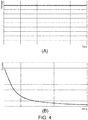
- FIG. 4 illustrates the changes in voltage and current during such constant-voltage charging. More specifically, FIG. 4(A) shows the temporal change in the terminal voltage of the rechargeable battery 14 during constant-voltage charging, and FIG. 4(B) shows the temporal change in the current flowing through the rechargeable battery 14 during constant-voltage charging. As illustrated in FIG. 4(A) , during constant-voltage charging the terminal voltage of the rechargeable battery 14 is constant. Meanwhile, as illustrated in FIG. 4(B) , the current flowing through the rechargeable battery 14 decreases as the SOC increases over time.
- FIG. 5 illustrates the changes in voltage and current when a short-circuit occurs in the rechargeable battery 14 while the rechargeable battery 14 is undergoing constant-voltage charging. More specifically, FIG. 5(A) shows the temporal change in the terminal voltage of the rechargeable battery 14 during constant-voltage charging, and FIG. 5(B) shows the temporal change in the current flowing through the rechargeable battery 14 during constant-voltage charging. Note that in FIG. 5 , the short-circuit progresses rapidly starting from near times t3 and t4. As illustrated in FIG. 5(A) , during constant-voltage charging the terminal voltage of the rechargeable battery 14 is constant. However, although when operating normally the current flowing through the rechargeable battery 14 decreases over time as illustrated in FIG.
- the current increases over time and increases rapidly from times t3 and t4 and on.
- I1 is on the order of approximately 0.5 to 0.6A
- I4 is on the order of approximately 1.2A.
- the time from time t1 to t4 is approximately 20 to 30 hours
- the time from time t2 to t3 is approximately several hours
- the time from time t3 to t4 is on the order of approximately 30 minutes to an hour.
- the example time periods given above are different depending on the type of rechargeable battery 14 and the state of progress of the short-circuit, of course.
- FIG. 6 illustrates the temporal changes in voltage and current upon transitioning to constant-current charging after a short-circuit has occurred. More specifically, FIG. 6(A) shows the temporal change in voltage after the short-circuit has occurred, and FIG. 6(B) shows the temporal change in current after the short-circuit has occurred. As illustrated in FIG. 6(B) , upon transitioning to constant-current charging the current flowing through the rechargeable battery 14 becomes constant. Moreover, as illustrated in FIG. 6(A) , upon transitioning to constant-current charging when a short-circuit has occurred, immediately after the short-circuit occurs the voltage of the rechargeable battery 14 decreases rapidly, and then as charging progresses the voltage increases gradually and begins to approach a prescribed voltage.
- the current increases in response to the decrease in internal resistance caused by the reduction in the number of cells.
- the alternator 15 or the like has a feature for implementing restrictions on current (or if there is an upper limit on current supply capacity)
- the current is restricted to be constant, which results in a transition to substantially constant-current charging.
- the voltage increases according to the dispersion of sulfate contained in the electrolyte. Then, once the amount of lead sulfate contained in the electrode plates becomes small, the voltage increases rapidly due to hydrogen and oxygen overvoltage, thus causing electrolysis of water, and the voltage becomes substantially constant (at 2.75V per cell, for example).
- the voltage of one cell of the rechargeable battery 14 be Vc
- the number of short-circuited cells be n
- the number of cells in the rechargeable battery 14 be N
- the occurrence of a short-circuit is predicted by detecting the current increase illustrated in FIG. 5 corresponding to when a short-circuit occurs, and the occurrence of a short-circuit is detected by detecting the voltage decrease the illustrated in FIG. 6 .
- Positive electrode Lead dioxide (PbSO 2 ) ⁇ Lead sulfate (PbSO 4 )
- Negative electrode Lead (Pb) ⁇ Lead sulfate (PbSO 4 )
- lead sulfate has low conductivity, is difficult to dissolve in water, and has large volume (low specific gravity) in comparison to lead and lead dioxide.
- This lead sulfate is produced during discharge and accumulates on the positive and negative electrode plates but sometimes peels off due to vibrations or the like as the vehicle is traveling and bridges between the positive electrodes and negative electrodes.
- lead sulfate crystals can form depending on the usage conditions of the rechargeable battery 14 (for example, when overdischarged or when the total amount of time spent in the discharged state is large), and these lead sulfate crystals sometimes bridge between the positive electrodes and negative electrodes.
- the controller 10 controls the alternator 15 to perform constant-current charging.
- the voltage increases as illustrated in FIG. 3(A) .
- the controller 10 controls the alternator 15 to transition to constant-voltage charging.
- this determination may be made on the basis of several measurement results or this determination may be made on the basis of the average value of several measurements, for example.
- the calculated A has a positive value, it is determined that a short-circuit may be occurring in the rechargeable battery 14 (the likelihood that a short-circuit is currently in the process of developing is high), and this information is conveyed to the user of the vehicle, for example.
- the current flowing through the rechargeable battery 14 is detected and the slope A of the current is calculated on the basis of the detection results in the same manner as described above. Then, if the calculated slope A of the current is still a positive value or if the slope A of the current has increased, it is determined that a short-circuit is close to occurring, this information is conveyed to the user, and in order to inhibit occurrence of a short-circuit, restrictions are implemented on charging of the rechargeable battery 14, for example. For example, during constant-voltage charging the alternator 15 is controlled to set the charge voltage to lower than normal.
- the controller 10 determines that a short-circuit has occurred and terminates charging. More specifically, in FIG. 6(A) the time from time t5 to t6 is approximately several minutes and the time from time t6 to t7 is approximately 1 day, and therefore these time periods are taken into account in detecting occurrence of short-circuits. This makes it possible to prevent the rechargeable battery 14 from generating heat or suffering damage.
- short-circuits in the rechargeable battery 14 are predicted from temporal changes in current during constant-voltage charging, which makes it possible to predict such short-circuits in advance and then notify the user or implement restrictions on charging, for example.
- the occurrence of the short-circuit is detected from temporal changes in voltage and then the user is notified or restrictions are implemented on charging, for example, thereby making it possible to prevent further damage to the rechargeable battery 14.
- FIG. 7 is a flowchart for explaining an example of a process that is executed in the embodiments of the present invention. Once the flowchart illustrated in FIG. 7 is started, the following steps are executed.
- step S10 the CPU 10a of the controller 10 determines whether to transition to constant-voltage charging. Upon determining to transition to constant-voltage charging (Y in step S10), the CPU 10a proceeds to step S11, and otherwise, the CPU 10a continues to repeat the same process. For example, when the SOC of the rechargeable battery 14 becomes greater than or equal to 90%, the CPU 10a determines to transition to constant-voltage charging and proceeds to step S11.
- step S11 the CPU 10a executes a process of calculating the temporal slope A of the current flowing from the alternator 15 to the rechargeable battery 14. The details of this process will be described later with reference to FIG. 8 .
- step S12 the CPU 10a determines whether the slope A calculated in step S11 is greater than a prescribed threshold value Th1. Upon determining that A>Th1 (where Th1 ⁇ 0) (Y in step S12), the CPU 10a proceeds to step S13, and otherwise (N in step S12), the CPU 10a ends the process.
- Th1 can be set to an appropriate value on the basis of the type of rechargeable battery 14 or the length of ⁇ T, for example.
- step S13 the CPU 10a notifies the user of the possibility of occurrence of a short-circuit via the communication unit 10d. More specifically, by notifying upstream devices via the communication unit 10d, the user can be warned via audio, text, or the like of the possibility that a short-circuit may occur in the rechargeable battery 14.
- step S14 the CPU 10a determines whether a prescribed period of time has elapsed. Upon determining that the prescribed period of time has elapsed (Y in step S14), the CPU 10a proceeds to step S15, and otherwise (N in step S14), the CPU 10a continues to repeat the same process. For example, if several hours have elapsed from when a determination of Y was obtained in step S12, the CPU 10a determines Y and proceeds to step S15.
- this period of time can be set to an appropriate value on the basis of the type of rechargeable battery 14 or the like.
- step S15 the CPU 10a executes the process of calculating the temporal slope A of the current flowing from the alternator 15 to the rechargeable battery 14. The details of this process will be described later with reference to FIG. 8 .
- step S16 the CPU 10a determines whether the slope A calculated in step S15 is greater than a prescribed threshold value Th2 (where Th2>Th1). Upon determining that A>Th2 (Y in step S16), the CPU 10a proceeds to step S17, and otherwise (N in step S16), the CPU 10a returns to step S14 and repeats the same process as described above.
- Th2 can be set to an appropriate value on the basis of the type of rechargeable battery 14 or the length of ⁇ T, for example.
- step S17 the CPU 10a notifies the user via the communication unit 10d that a short-circuit is close to occurring. More specifically, by notifying upstream devices via the communication unit 10d, the user can be informed via audio, text, or the like that occurrence of a short-circuit in the rechargeable battery 14 is imminent.
- step S18 the CPU 10a controls the alternator 15 to implement restrictions on charging. More specifically, the CPU 10a controls the alternator 15 to reduce the voltage generated thereby and thereby restricts charging. This makes it possible to inhibit the change of lead sulfate into lead dioxide or lead, thereby making it possible to inhibit progression of development of short-circuits.
- step S19 the CPU 10a determines whether a transition to constant-current charging has occurred. Upon determining that a transition to constant-current charging has occurred (Y in step S19), the CPU 10a proceeds to step S20, and otherwise, the CPU 10a continues to repeat the same process. For example, when an excessive current has flowed through the rechargeable battery 14 due to a short-circuit, the CPU 10a determines that a transition to constant-current charging has occurred and proceeds to step S20.
- step S20 the CPU 10a executes a process of calculating the temporal slope B of the voltage applied to the rechargeable battery 14 by the alternator 15. The details of this process will be described later with reference to FIG. 9 .
- step S21 the CPU 10a determines whether the slope B calculated in step S20 is less than a prescribed threshold value Th3. Upon determining that B ⁇ Th3 (where Th3 ⁇ 0) (Y in step S21), the CPU 10a proceeds to step S22, and otherwise (N in step S21), the CPU 10a continues to repeat the same process.
- the value of Th3 can be set to an appropriate value on the basis of the type of rechargeable battery 14 or the length of ⁇ T, for example.
- step S22 the CPU 10a notifies the user via the communication unit 10d that a short-circuit has occurred. More specifically, by notifying upstream devices via the communication unit 10d, the user can be informed via audio, text, or the like that a short-circuit has occurred in the rechargeable battery 14.
- step S23 the CPU 10a controls the alternator 15 to terminate charging. More specifically, the CPU 10a controls the alternator 15 to make the alternator 15 stop generating power and thereby terminates charging. This makes it possible to prevent the rechargeable battery 14 from generating heat or suffering damage, for example.
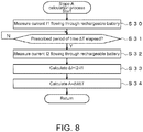
- step S11 and step S15 of FIG. 7 will be described in detail with reference to FIG. 8 .
- step S30 CPU 10a references the output of the current sensor 12 to measure the current I1 that is flowing through the rechargeable battery 14 at that point in time.
- step S31 the CPU 10a determines whether a prescribed period of time ⁇ T has elapsed. Upon determining that the prescribed period of time ⁇ T has elapsed (Y in step S31), the CPU 10a proceeds to step S32, and otherwise (N in step S31), the CPU 10a continues to repeat the same process. For example, if one hour or several hours have elapsed as the period of time ⁇ T, the CPU 10a determines Y and proceeds to step S32.
- this period of time ⁇ T may be set to be longer or shorter than described above according to the accuracy of the current sensor 12, observational error, or the like.
- step S32 CPU 10a references the output of the current sensor 12 to measure the current I2 that is flowing through the rechargeable battery 14 at that point in time.
- step S20 of FIG. 7 will be described in detail with reference to FIG. 9 .
- step S50 CPU 10a references the output of the voltage sensor 11 to measure the terminal voltage V1 of the rechargeable battery 14 at that point in time.
- step S51 the CPU 10a determines whether a prescribed period of time ⁇ T has elapsed. Upon determining that the prescribed period of time ⁇ T has elapsed (Y in step S51), the CPU 10a proceeds to step S52, and otherwise (N in step S51), the CPU 10a continues to repeat the same process. For example, if several minutes or several hours have elapsed as the period of time ⁇ T, the CPU 10a determines Y and proceeds to step S52.
- this period of time ⁇ T may be set to be longer or shorter than described above according to at which of the timings in FIG. 6(A) the detection is performed.
- step S52 CPU 10a references the output of the voltage sensor 11 to measure the terminal voltage V2 of the rechargeable battery 14 at that point in time.
- the transition to constant-voltage charging is made when the SOC becomes greater than or equal to 90% and occurrence of short-circuits is then predicted from temporal changes in current during this constant-voltage charging
- the transition to constant-voltage charging and the processes described above can be executed at an SOC of less than 90%.
- a temporary transition to constant-voltage charging may be made in order to predict short-circuits, and the occurrence of short-circuits may be predicted from temporal changes in current observed while doing this.
- the rechargeable battery 14 when the rechargeable battery 14 is new, changes in current during constant-voltage charging may be stored in the RAM 10c as parameters 10ca, and the occurrence of short-circuits may be predicted or determined using these changes in current from when the rechargeable battery 14 was new as a reference, for example. More specifically, the slope of the current when the rechargeable battery 14 is new can be stored as A0 (typically a negative value), and the difference (A-AO) against the A at a given point in time can be calculated, for example. If this difference is close to zero, it can be determined that the rechargeable battery 14 is operating normally, and when this difference becomes greater than or equal to a prescribed threshold value (for example, a positive threshold value), the occurrence of a short-circuit can be predicted.
- a prescribed threshold value for example, a positive threshold value
- the slope of the current changes depending on the SOC of the rechargeable battery 14
- the slope may be obtained and stored at each SOC, and the slope corresponding to the SOC at that given point in time can be retrieved to then execute the process described above.
- the temperature of the electrolyte may be estimated using the temperature sensor 13, and the estimated temperature may be used to convert to values in some reference state.
- the current and voltage measured when the temperature of the electrolyte estimated by the temperature sensor 13 is 30°C may be normalized to a corresponding value at a reference state of 25°C by using a conversion table or the like, for example.
- the alternator 15 or the like were described as being assumed to have a feature for implementing restrictions on current, when no such features for implementing restrictions on current are present, the current illustrated in FIG. 6(B) changes depending on the RPM of the engine 16 and the like, for example.
- the voltage in FIG. 6(A) changes in response to these changes in current.
- the output signal from the current sensor 12 may be referenced, and if the temporal rate of increase in the charge current is increasing over time (as illustrated in FIG. 5(B) ), it may be determined that there is a possibility that the rechargeable battery 14 is short-circuiting. In other words, if the time derivative of the charge current during constant-voltage charging is increasing over time (and exceeds a prescribed threshold value, for example), it may be determined that there is a possibility that the rechargeable battery 14 is short-circuiting.
Abstract
Description
- The present invention relates to a rechargeable battery short-circuit prediction device and a rechargeable battery short-circuit prediction method.
- Rechargeable batteries installed in automobiles are configured by combining a plurality of cells to achieve a prescribed voltage. For example, in lead-acid batteries installed in automobiles, each cell has a voltage of approximately 2V, and six of these cells are connected in series to achieve a voltage of approximately 12V.
- In these types of rechargeable batteries that are configured by combining a plurality of cells, repeated charging/discharging causes various changes to occur in each cell, which can sometimes result in short-circuits occurring within the rechargeable battery.
- When a short-circuit occurs in such a rechargeable battery, the original output voltage of approximately 12V decreases to approximately 10V, and the rechargeable battery can no longer be used normally.
- When a rechargeable battery with an internal short-circuit is charged under the same conditions as a rechargeable battery that is operating normally, the voltage applied to a single cell becomes higher than normal, which results in overcharging and problems such as temperature increases and production of hydrogen.
- Accordingly, the technologies disclosed in
Patent Documents 1 to 3 exist as technologies for detecting such short-circuits in rechargeable batteries. -
Patent Document 1 discloses a technology in which a reference voltage relative to an integrated current value is stored and compared to a current detected voltage, and when the current detected voltage is less than the reference voltage, it is determined that an internal short-circuit is present in a battery cell. - Patent Document 2 discloses a technology which determines cell short-circuits using both a comparison between a reference voltage and a charging/discharging terminal voltage as well as a deterioration factor based on the time elapsed from when charging/discharging stopped, the stable OCV, and a relaxation function F(t).
-
Patent Document 3 discloses a technology in which a voltage at a time when the current flowing becomes less than or equal to a prescribed value is compared to a voltage at after a prescribed period of time since the current became less than or equal to the prescribed value has elapsed, and if the difference therebetween is greater than or equal to a prescribed value, a short-circuit is determined to be present. -
- Patent Document 1: Japanese Patent Application Laid-Open Publication No.
2011-135656 - Patent Document 2: Japanese Patent Application Laid-Open Publication No.
2011-112453 - Patent Document 3: Japanese Patent Application Laid-Open Publication No.
2009-170397 - However, although the technologies disclosed in
Patent Documents 1 to 3 as described above make it possible to detect whether a short-circuit has occurred in a rechargeable battery, these technologies lack the ability to predict the occurrence of such short-circuits. - The present invention was made in light of the foregoing and aims to provide a rechargeable battery short-circuit prediction device and a rechargeable battery short-circuit prediction method that make it possible to predict the occurrence of short-circuits in a rechargeable battery.
- In order to solve the above-mentioned problems, a rechargeable battery short-circuit prediction device that predicts short-circuits in a rechargeable battery, the device comprising one or more processors connected to a current sensor that detects a charge current of the rechargeable battery, wherein the one or more processors are programmed to: while the rechargeable battery is being charged, receive a current signal indicating the charge current from the current sensor; detect temporal changes in the charge current indicated by the current signal; determine, when the charge current increases over time, that there is a possibility that the rechargeable battery is short-circuiting; and output data indicating a determined result.
- This configuration makes it possible to predict the occurrence of short-circuits in the rechargeable battery.
- In the rechargeable battery short-circuit prediction device of the present invention, the current signal indicating the charge current from the current sensor may be received while the rechargeable battery is being charged at a constant voltage.
- This configuration makes it possible to more reliably predict the possibility of occurrence of short-circuits in the rechargeable battery.
- In the rechargeable battery short-circuit prediction device of the present invention, the current signal indicating the charge current from the current sensor may be received while the rechargeable battery is being charged at a constant voltage, and when a temporal rate of increase in the charge current corresponding to the current signal increases over time, the device determines that there is a possibility that the rechargeable battery is short-circuiting.
- This configuration makes it possible to more reliably detect the possibility of short-circuits from the temporal rate of increase in the charge current.
- In the rechargeable battery short-circuit prediction device of the present invention, further including: a voltage sensor connected to the one or more processors that detects a charge voltage of the rechargeable battery, wherein while the rechargeable battery is being charged, the device receives a voltage signal indicating the charge voltage from the voltage sensor, wherein the device detects temporal changes in the charge voltage indicated by the voltage signal, and wherein when the charge voltage decreases over time, the device determines that the rechargeable battery has short-circuited.
- This configuration makes it possible to predict the occurrence of short-circuits in the rechargeable battery and also to determine that a short-circuit has occurred.
- In the rechargeable battery short-circuit prediction device of the present invention, the voltage signal indicating the charge voltage from the voltage sensor may be received while the rechargeable battery is being charged at a constant current.
- This configuration makes it possible to more reliably determine occurrence of short-circuits in the rechargeable battery.
- In the rechargeable battery short-circuit prediction device of the present invention, upon determining that there is a possibility that the rechargeable battery has short-circuited or determining that a short-circuit has occurred, the device may issue a warning.
- This configuration makes it possible to notify the user of the possibility that a short-circuit will occur or of the occurrence of a short-circuit.
- In the rechargeable battery short-circuit prediction device of the present invention, upon determining that there is a possibility that the rechargeable battery has short-circuited or determining that a short-circuit has occurred, the device may restrict or terminate charging of the rechargeable battery.
- This configuration makes it possible to inhibit progression of a short-circuit by restricting or terminating charging.
- In the rechargeable battery short-circuit prediction device of the present invention, the device may compare temporal change in the charge current at a given point in time against past temporal change in the charge current, and, when the charge current has transitioned from decreasing over time to increasing over time, determines that there is a possibility that the rechargeable battery has short-circuited.
- This configuration makes it possible to more accurately predict the possibility of occurrence of a short-circuit by comparing against past measurement values.
- In the rechargeable battery short-circuit prediction device of the present invention, the device may include the one or more processors, the current sensor that detects the charge current of the rechargeable battery, and the voltage sensor that detects the charge voltage of the rechargeable battery.
- This configuration makes it possible to predict the occurrence of short-circuits in the rechargeable battery.
- A rechargeable battery short-circuit prediction method that predicts short-circuits in a rechargeable battery and is executed by one or more programmable processors connected to a current sensor that detects a charge current of the rechargeable battery, the method including: while the rechargeable battery is being charged, receiving a current signal indicating the charge current from the current sensor; detecting temporal changes in the charge current indicated by the current signal; determining, when the charge current increases over time, that there is a possibility of a short-circuit in the rechargeable battery; and outputting data indicating a determined result.
- This configuration makes it possible to predict the occurrence of short-circuits in the rechargeable battery.
- The present invention makes it possible to provide a rechargeable battery short-circuit prediction device and a rechargeable battery short-circuit prediction method that can predict the occurrence of short-circuits in a rechargeable battery.
-
-
FIG. 1 illustrates an example configuration of a rechargeable battery short-circuit prediction device according to an embodiment of the present invention. -
FIG. 2 is a block diagram illustrating a detailed configuration example for the controller inFIG. 1 . -
FIG. 3 illustrates temporal changes in voltage and current when a rechargeable battery that is operating normally is charged at constant current. -
FIG. 4 illustrates temporal changes in voltage and current when a rechargeable battery that is operating normally is charged at constant voltage. -
FIG. 5 illustrates temporal changes in voltage and current when a rechargeable battery in which a short-circuit is developing is charged at constant current. -
FIG. 6 illustrates temporal changes in voltage and current when a rechargeable battery in which a short-circuit has occurred is charged at constant voltage. -
FIG. 7 is a flowchart for explaining the operation of embodiments of the present invention. -
FIG. 8 is a flowchart for explaining the details of the current slope A calculation process illustrated inFIG. 7 . -
FIG. 9 is a flowchart for explaining the details of the voltage slope B calculation process illustrated inFIG. 7 . - Next, embodiments of the present invention will be described.
-
FIG. 1 illustrates a vehicle power supply system having a rechargeable battery short-circuit prediction device according to an embodiment of the present invention. In this figure, a rechargeable battery short-circuit prediction device 1 primarily includes acontroller 10, avoltage sensor 11, acurrent sensor 12, and atemperature sensor 13 and predicts the occurrence of short-circuits in arechargeable battery 14. Moreover, at least one of thevoltage sensor 11, thecurrent sensor 12, and thetemperature sensor 13 may be configured as a separate component, and detection signals therefrom may be taken as input. - Here, the
controller 10 references the outputs of thevoltage sensor 11, thecurrent sensor 12, and thetemperature sensor 13 to detect the state of therechargeable battery 14 and controls the state of charge of therechargeable battery 14 by controlling a voltage generated by analternator 15. Thevoltage sensor 11 detects the terminal voltage of therechargeable battery 14 and reports this voltage to thecontroller 10 as a voltage signal. Thecurrent sensor 12 detects the current flowing through therechargeable battery 14 and reports this current to thecontroller 10 as a current signal. Thetemperature sensor 13 detects the temperature of the electrolyte or surrounding environment of therechargeable battery 14 and reports this temperature to thecontroller 10 as a temperature signal. Note that rather than thecontroller 10 controlling the state of charge of therechargeable battery 14 by controlling the voltage generated by thealternator 15, an electric control unit (ECU; not illustrated in the figure) may control the state of charge, for example. - The
rechargeable battery 14 is a rechargeable battery having an electrolyte, such as a lead-acid battery, a nickel-cadmium battery, or a nickel-metal hydride battery, for example; is charged by thealternator 15; powers astarter motor 17 to start an engine; and supplies power to aload 18. Thealternator 15 is powered by anengine 16, generates AC power and converts that AC power to DC power via a rectifier circuit, and charges therechargeable battery 14. Thealternator 15 is controlled by thecontroller 10, and the voltage generated can be adjusted. - The
engine 16 is a reciprocating engine or rotary engine such as a gasoline engine or diesel engine, for example, is started by thestarter motor 17, drives drive wheels via a transmission to supply propulsive power to the vehicle, and also drives thealternator 15 to make thealternator 15 generate electrical power. Thestarter motor 17 is a DC motor, for example, and generates a rotational force using electrical power supplied from therechargeable battery 14 to start theengine 16. Theload 18 is a power steering motor, a defogger, a seat heater, an ignition coil, a car audio system, a car navigation unit, or the like, for example, and runs on electrical power from therechargeable battery 14. -
FIG. 2 illustrates a detailed example configuration for thecontroller 10 illustrated inFIG. 1 . As illustrated in the figure, thecontroller 10 includes a central processing unit (CPU) 10a, a read-only memory (ROM) 10b, a random-access memory (RAM) 10C, a communication unit 10d, and an interface (I/F) 10e. Here, the CPU 10a controls the other components according to a program 10ba stored in the ROM 10b. The ROM 10b is semiconductor memory or the like and stores the program 10ba and the like. The RAM 10c is semiconductor memory or the like and stores data generated when executing the program 10ba or parameters 10ca such as a table (described later). The communication unit 10d communicates with upstream devices such as an electronic control unit (ECU) and sends detected information or control information to the upstream devices. The I/F 10e converts signals supplied by thevoltage sensor 11, thecurrent sensor 12, and thetemperature sensor 13 to digital signals and takes these digital signals as input and also controls thealternator 15, thestarter motor 17, and the like by supplying drive current thereto. Note that although in the example inFIG. 2 the configuration includes the CPU 10a as a processor, a digital signal processor (DSP) or field-programmable gate array (FPGA) may be included. Moreover, rather than including a single processor, a plurality of these processors may be included. - Next, the operation of embodiments of the present invention will be described. Note that below, after describing the principle of operation of the embodiments of the present invention, the detailed operation will be described.
- First, the principle of operation of the embodiments of the present invention will be described. While charging the
rechargeable battery 14, when the state of charge (SOC) of therechargeable battery 14 is low (less than 90%, for example), thealternator 15 charges therechargeable battery 14 at a constant current (constant-current charging). Here, this charge current can have a magnitude on the order of several dozen A to several hundred A, for example. The charge current may also be greater than or less than this, of course. -
FIG. 3 illustrates the temporal changes in voltage and current during constant-current (CC) charging when therechargeable battery 14 is operating normally (when no short-circuits have occurred). More specifically,FIG. 3(A) shows the temporal change in the terminal voltage of therechargeable battery 14 during constant-current charging, andFIG. 3(B) shows the temporal change in the current flowing through therechargeable battery 14 during constant-current charging. As illustrated inFIG. 3(B) , during constant-current charging the current flowing through therechargeable battery 14 is constant. Meanwhile, as illustrated inFIG. 3(A) , the terminal voltage of therechargeable battery 14 increases over time. - Then, when the SOC of the
rechargeable battery 14 becomes high (greater than or equal to 90%, for example), therechargeable battery 14 is switched to constant-voltage (CV) charging.FIG. 4 illustrates the changes in voltage and current during such constant-voltage charging. More specifically,FIG. 4(A) shows the temporal change in the terminal voltage of therechargeable battery 14 during constant-voltage charging, andFIG. 4(B) shows the temporal change in the current flowing through therechargeable battery 14 during constant-voltage charging. As illustrated inFIG. 4(A) , during constant-voltage charging the terminal voltage of therechargeable battery 14 is constant. Meanwhile, as illustrated inFIG. 4(B) , the current flowing through therechargeable battery 14 decreases as the SOC increases over time. Then, when the SOC becomes 100% the current takes a value close to zero. Here, as one example, if the output voltage of thealternator 15 is 14.4V, this voltage is applied uniformly to each of six cells in therechargeable battery 14, and therefore a voltage of 2.4V (=14.4V/6) is applied to each cell. -
FIG. 5 illustrates the changes in voltage and current when a short-circuit occurs in therechargeable battery 14 while therechargeable battery 14 is undergoing constant-voltage charging. More specifically,FIG. 5(A) shows the temporal change in the terminal voltage of therechargeable battery 14 during constant-voltage charging, andFIG. 5(B) shows the temporal change in the current flowing through therechargeable battery 14 during constant-voltage charging. Note that inFIG. 5 , the short-circuit progresses rapidly starting from near times t3 and t4. As illustrated inFIG. 5(A) , during constant-voltage charging the terminal voltage of therechargeable battery 14 is constant. However, although when operating normally the current flowing through therechargeable battery 14 decreases over time as illustrated inFIG. 4(B) , in the example inFIG. 5(B) , the current increases over time and increases rapidly from times t3 and t4 and on. Note that inFIG. 5 , I1 is on the order of approximately 0.5 to 0.6A, and I4 is on the order of approximately 1.2A. Moreover, the time from time t1 to t4 is approximately 20 to 30 hours, the time from time t2 to t3 is approximately several hours, and the time from time t3 to t4 is on the order of approximately 30 minutes to an hour. The example time periods given above are different depending on the type ofrechargeable battery 14 and the state of progress of the short-circuit, of course. - Here, when a short-circuit occurs in any of the cells of the
rechargeable battery 14, the output voltage of that cell approaches 0V, and therefore the voltage applied to the other cells increases as a result. Thus, as illustrated inFIG. 5(B) , the charge current increases rapidly. If thealternator 15 or the like has a feature for implementing restrictions when the current exceeds a prescribed value (or if there is an upper limit on current supply capacity), the current from thealternator 15 becomes constant, which results in a transition to substantially constant-current charging. -
FIG. 6 illustrates the temporal changes in voltage and current upon transitioning to constant-current charging after a short-circuit has occurred. More specifically,FIG. 6(A) shows the temporal change in voltage after the short-circuit has occurred, andFIG. 6(B) shows the temporal change in current after the short-circuit has occurred. As illustrated inFIG. 6(B) , upon transitioning to constant-current charging the current flowing through therechargeable battery 14 becomes constant. Moreover, as illustrated inFIG. 6(A) , upon transitioning to constant-current charging when a short-circuit has occurred, immediately after the short-circuit occurs the voltage of therechargeable battery 14 decreases rapidly, and then as charging progresses the voltage increases gradually and begins to approach a prescribed voltage. - More particularly, if a short-circuit occurs in one cell of the six cells of the
rechargeable battery 14, for example, the current increases in response to the decrease in internal resistance caused by the reduction in the number of cells. If thealternator 15 or the like has a feature for implementing restrictions on current (or if there is an upper limit on current supply capacity), once the current exceeds a prescribed value the current is restricted to be constant, which results in a transition to substantially constant-current charging. After transitioning to constant-current charging, the voltage increases according to the dispersion of sulfate contained in the electrolyte. Then, once the amount of lead sulfate contained in the electrode plates becomes small, the voltage increases rapidly due to hydrogen and oxygen overvoltage, thus causing electrolysis of water, and the voltage becomes substantially constant (at 2.75V per cell, for example). - Therefore, letting the voltage of one cell of the
rechargeable battery 14 be Vc, the number of short-circuited cells be n, and the number of cells in therechargeable battery 14 be N, when the terminal voltage V takes a voltage close to V=(N-n)×Vc or a voltage slightly greater than that during constant-current charging, it can be determined that a short-circuit has occurred. For example, in an automobile, when arechargeable battery 14 in which the number of cells N=6 is charged at 14.4V, then Vc=2.4V, and so if one cell short-circuits the terminal voltage V becomes equal to (6-1)×2.4=12.0V or takes a voltage slightly greater than that (approximately 13.6V, for example). In other words, in an automobile, if after transitioning from constant-voltage charging to constant-current charging the terminal voltage V becomes equal to 12.0V or takes a voltage slightly greater than that, it can be determined that a short-circuit has occurred in one cell. Note that inFIG. 6 , V1 is the voltage for when six cells are operating normally and is thus approximately 2.4V×6=14.4V. The calculation described above for when a short-circuit occurs in one cell would be 2.4V×5=12.0V, but because as illustrated inFIG. 5(B) the current increases due to the symptoms of the short-circuit, the voltage becomes slightly greater than 12.0V as a result (approximately 13.6V, for example, as described above). Then, as charging progresses and the amount of lead sulfate contained in the electrode plates becomes small, oxygen and hydrogen are produced as a result of electrolysis, and sulfate (the electrolyte) disperses, thereby causing the voltage to gradually increase. Next, upon approaching a full charge, due to hydrogen and oxygen overvoltage the per-cell voltage Vc approaches 2.75V. Therefore, as illustrated inFIG. 6(A) , when a short-circuit occurs in one cell, the terminal voltage V begins to approach V4 (=2.75V×5=13.75V) as time elapses. - In the present embodiment, the occurrence of a short-circuit is predicted by detecting the current increase illustrated in
FIG. 5 corresponding to when a short-circuit occurs, and the occurrence of a short-circuit is detected by detecting the voltage decrease the illustrated inFIG. 6 . - Here, one possible cause for the change illustrated in
FIG. 5 to occur is as follows. In other words, for a lead-acid battery that is the rechargeable battery, the chemical changes that occur at the electrodes during charging and discharging are as follows. - Positive electrode: Lead sulfate (PbSO4) → Lead dioxide (PbO2)
Negative electrode: Lead sulfate (PbSO4) → Lead (Pb) - Positive electrode: Lead dioxide (PbSO2) → Lead sulfate (PbSO4)
Negative electrode: Lead (Pb) → Lead sulfate (PbSO4) - Here, lead sulfate has low conductivity, is difficult to dissolve in water, and has large volume (low specific gravity) in comparison to lead and lead dioxide. This lead sulfate is produced during discharge and accumulates on the positive and negative electrode plates but sometimes peels off due to vibrations or the like as the vehicle is traveling and bridges between the positive electrodes and negative electrodes. In other cases, lead sulfate crystals can form depending on the usage conditions of the rechargeable battery 14 (for example, when overdischarged or when the total amount of time spent in the discharged state is large), and these lead sulfate crystals sometimes bridge between the positive electrodes and negative electrodes.
- Thus, when lead sulfate bridges between the positive electrodes and negative electrodes, because the lead sulfate has low conductivity as described above, short-circuits and the like do not occur immediately. However, in such states, charging causes the lead sulfate to gradually change into lead dioxide or lead, which are conductive. Therefore, it is conceivable that, as illustrated in
FIG. 5(B) , current gradually increases starting from before a short-circuit occurs, and then once the short-circuit occurs a large current flows. Note that although the above is only a hypothesis due to the difficulty of observing the phenomenon that is actually occurring within therechargeable battery 14, the fact that current changes of the type illustrated inFIG. 5 do occur when a short-circuit occurs has been confirmed in actual measurements. - Next, the operation of embodiments of the present invention will be described in more detail. When the SOC of the
rechargeable battery 14 is less than 90%, for example, thecontroller 10 controls thealternator 15 to perform constant-current charging. Thus, as charging progresses the voltage increases as illustrated inFIG. 3(A) . - When the SOC of the
rechargeable battery 14 becomes greater than or equal to 90%, for example, thecontroller 10 controls thealternator 15 to transition to constant-voltage charging. While performing constant-voltage charging, thecontroller 10 uses thecurrent sensor 12 to detect the current (charge current) flowing through therechargeable battery 14 and detects temporal changes in this current. In other words, letting the charge current detected at a given point in time be I1 and the charge current detected after a prescribed period of time ΔT has elapsed be I2, A = (I2-I1)/ΔT is calculated as the temporal slope A of the current. - Thus, when the calculated A is a negative value, this corresponds to the current decreasing as illustrated in
FIG. 4(B) , and therefore it can be determined that therechargeable battery 14 is operating normally. - Meanwhile, when the calculated A is a positive value, this corresponds to the current increasing as illustrated in
FIG. 5(B) , and therefore it can be determined that a short-circuit may be occurring in therechargeable battery 14. Note that in order to avoid incorrect determinations due to measurement error or the like, this determination may be made on the basis of several measurement results or this determination may be made on the basis of the average value of several measurements, for example. - When the calculated A has a positive value, it is determined that a short-circuit may be occurring in the rechargeable battery 14 (the likelihood that a short-circuit is currently in the process of developing is high), and this information is conveyed to the user of the vehicle, for example.
- Next, after a prescribed period of time has elapsed, the current flowing through the
rechargeable battery 14 is detected and the slope A of the current is calculated on the basis of the detection results in the same manner as described above. Then, if the calculated slope A of the current is still a positive value or if the slope A of the current has increased, it is determined that a short-circuit is close to occurring, this information is conveyed to the user, and in order to inhibit occurrence of a short-circuit, restrictions are implemented on charging of therechargeable battery 14, for example. For example, during constant-voltage charging thealternator 15 is controlled to set the charge voltage to lower than normal. - If a short-circuit occurs even after such implementing such control, the current increases rapidly as illustrated in
FIG. 5(B) , and thealternator 15 reaches a maximum current and transitions to substantially constant-current charging. In this case, the terminal voltage decreases as illustrated inFIG. 6(A) , and therefore upon detecting such a decrease in charge voltage, thecontroller 10 determines that a short-circuit has occurred and terminates charging. More specifically, inFIG. 6(A) the time from time t5 to t6 is approximately several minutes and the time from time t6 to t7 is approximately 1 day, and therefore these time periods are taken into account in detecting occurrence of short-circuits. This makes it possible to prevent therechargeable battery 14 from generating heat or suffering damage. - As described above, in the embodiments of the present invention short-circuits in the
rechargeable battery 14 are predicted from temporal changes in current during constant-voltage charging, which makes it possible to predict such short-circuits in advance and then notify the user or implement restrictions on charging, for example. - Moreover, in the embodiments of the present invention, when a short-circuit occurs, the occurrence of the short-circuit is detected from temporal changes in voltage and then the user is notified or restrictions are implemented on charging, for example, thereby making it possible to prevent further damage to the
rechargeable battery 14. - Next, processes executed in the embodiments of the present invention will be described in detail with reference to
FIGs. 7 to 9 . -
FIG. 7 is a flowchart for explaining an example of a process that is executed in the embodiments of the present invention. Once the flowchart illustrated inFIG. 7 is started, the following steps are executed. - In step S10, the CPU 10a of the
controller 10 determines whether to transition to constant-voltage charging. Upon determining to transition to constant-voltage charging (Y in step S10), the CPU 10a proceeds to step S11, and otherwise, the CPU 10a continues to repeat the same process. For example, when the SOC of therechargeable battery 14 becomes greater than or equal to 90%, the CPU 10a determines to transition to constant-voltage charging and proceeds to step S11. - In step S11, the CPU 10a executes a process of calculating the temporal slope A of the current flowing from the
alternator 15 to therechargeable battery 14. The details of this process will be described later with reference toFIG. 8 . - In step S12, the CPU 10a determines whether the slope A calculated in step S11 is greater than a prescribed threshold value Th1. Upon determining that A>Th1 (where Th1≥0) (Y in step S12), the CPU 10a proceeds to step S13, and otherwise (N in step S12), the CPU 10a ends the process. Here, the value of Th1 can be set to an appropriate value on the basis of the type of
rechargeable battery 14 or the length of ΔT, for example. - In step S13, the CPU 10a notifies the user of the possibility of occurrence of a short-circuit via the communication unit 10d. More specifically, by notifying upstream devices via the communication unit 10d, the user can be warned via audio, text, or the like of the possibility that a short-circuit may occur in the
rechargeable battery 14. - In step S14, the CPU 10a determines whether a prescribed period of time has elapsed. Upon determining that the prescribed period of time has elapsed (Y in step S14), the CPU 10a proceeds to step S15, and otherwise (N in step S14), the CPU 10a continues to repeat the same process. For example, if several hours have elapsed from when a determination of Y was obtained in step S12, the CPU 10a determines Y and proceeds to step S15. Here, this period of time can be set to an appropriate value on the basis of the type of
rechargeable battery 14 or the like. - In step S15, the CPU 10a executes the process of calculating the temporal slope A of the current flowing from the
alternator 15 to therechargeable battery 14. The details of this process will be described later with reference toFIG. 8 . - In step S16, the CPU 10a determines whether the slope A calculated in step S15 is greater than a prescribed threshold value Th2 (where Th2>Th1). Upon determining that A>Th2 (Y in step S16), the CPU 10a proceeds to step S17, and otherwise (N in step S16), the CPU 10a returns to step S14 and repeats the same process as described above. Here, the value of Th2 can be set to an appropriate value on the basis of the type of
rechargeable battery 14 or the length of ΔT, for example. - In step S17, the CPU 10a notifies the user via the communication unit 10d that a short-circuit is close to occurring. More specifically, by notifying upstream devices via the communication unit 10d, the user can be informed via audio, text, or the like that occurrence of a short-circuit in the
rechargeable battery 14 is imminent. - In step S18, the CPU 10a controls the
alternator 15 to implement restrictions on charging. More specifically, the CPU 10a controls thealternator 15 to reduce the voltage generated thereby and thereby restricts charging. This makes it possible to inhibit the change of lead sulfate into lead dioxide or lead, thereby making it possible to inhibit progression of development of short-circuits. - In step S19, the CPU 10a determines whether a transition to constant-current charging has occurred. Upon determining that a transition to constant-current charging has occurred (Y in step S19), the CPU 10a proceeds to step S20, and otherwise, the CPU 10a continues to repeat the same process. For example, when an excessive current has flowed through the
rechargeable battery 14 due to a short-circuit, the CPU 10a determines that a transition to constant-current charging has occurred and proceeds to step S20. - In step S20, the CPU 10a executes a process of calculating the temporal slope B of the voltage applied to the
rechargeable battery 14 by thealternator 15. The details of this process will be described later with reference toFIG. 9 . - In step S21, the CPU 10a determines whether the slope B calculated in step S20 is less than a prescribed threshold value Th3. Upon determining that B<Th3 (where Th3≤0) (Y in step S21), the CPU 10a proceeds to step S22, and otherwise (N in step S21), the CPU 10a continues to repeat the same process. Here, the value of Th3 can be set to an appropriate value on the basis of the type of
rechargeable battery 14 or the length of ΔT, for example. - In step S22, the CPU 10a notifies the user via the communication unit 10d that a short-circuit has occurred. More specifically, by notifying upstream devices via the communication unit 10d, the user can be informed via audio, text, or the like that a short-circuit has occurred in the
rechargeable battery 14. - In step S23, the CPU 10a controls the
alternator 15 to terminate charging. More specifically, the CPU 10a controls thealternator 15 to make thealternator 15 stop generating power and thereby terminates charging. This makes it possible to prevent therechargeable battery 14 from generating heat or suffering damage, for example. - Next, the process illustrated in step S11 and step S15 of
FIG. 7 will be described in detail with reference toFIG. 8 . Once the process illustrated inFIG. 8 is started, the following steps are executed. - In step S30, CPU 10a references the output of the
current sensor 12 to measure the current I1 that is flowing through therechargeable battery 14 at that point in time. - In step S31, the CPU 10a determines whether a prescribed period of time ΔT has elapsed. Upon determining that the prescribed period of time ΔT has elapsed (Y in step S31), the CPU 10a proceeds to step S32, and otherwise (N in step S31), the CPU 10a continues to repeat the same process. For example, if one hour or several hours have elapsed as the period of time ΔT, the CPU 10a determines Y and proceeds to step S32. Here, this period of time ΔT may be set to be longer or shorter than described above according to the accuracy of the
current sensor 12, observational error, or the like. - In step S32, CPU 10a references the output of the
current sensor 12 to measure the current I2 that is flowing through therechargeable battery 14 at that point in time. - In step S33, the CPU 10a uses the formula ΔI=I2-I1 to calculate the current difference ΔI between the current I1 measured in step S30 and the current I2 measured in step S32.
- In step S34, the CPU 10a uses the formula A=ΔI/ΔT to calculate the current slope A on the basis of the current difference ΔI calculated in step S33 and the ΔT from step S31. Then, the CPU 10a returns to the original process.
- Next, the process illustrated in step S20 of
FIG. 7 will be described in detail with reference toFIG. 9 . Once the process illustrated inFIG. 9 is started, the following steps are executed. - In step S50, CPU 10a references the output of the
voltage sensor 11 to measure the terminal voltage V1 of therechargeable battery 14 at that point in time. - In step S51, the CPU 10a determines whether a prescribed period of time ΔT has elapsed. Upon determining that the prescribed period of time ΔT has elapsed (Y in step S51), the CPU 10a proceeds to step S52, and otherwise (N in step S51), the CPU 10a continues to repeat the same process. For example, if several minutes or several hours have elapsed as the period of time ΔT, the CPU 10a determines Y and proceeds to step S52. Here, this period of time ΔT may be set to be longer or shorter than described above according to at which of the timings in
FIG. 6(A) the detection is performed. - In step S52, CPU 10a references the output of the
voltage sensor 11 to measure the terminal voltage V2 of therechargeable battery 14 at that point in time. - In step S53, the CPU 10a uses the formula ΔV=V2-V1 to calculate the voltage difference ΔV between the voltage V1 measured in step S50 and the voltage V2 measured in step S52.
- In step S54, the CPU 10a uses the formula B=ΔV/ΔT to calculate the voltage slope B on the basis of the voltage difference ΔV calculated in step S53 and the ΔT from step S51. Then, the CPU 10a returns to the original process.
- The processes described above make it possible to implement the operation described above.
- The embodiments described above are only examples, and the present invention is not limited only to the embodiments described above. For example, although in the embodiments described above the transition to constant-voltage charging is made when the SOC becomes greater than or equal to 90% and occurrence of short-circuits is then predicted from temporal changes in current during this constant-voltage charging, the transition to constant-voltage charging and the processes described above can be executed at an SOC of less than 90%.
- Moreover, during constant-current charging, a temporary transition to constant-voltage charging may be made in order to predict short-circuits, and the occurrence of short-circuits may be predicted from temporal changes in current observed while doing this.
- Furthermore, although in the embodiments described above the occurrence of short-circuits is predicted or determined on the basis of currents I1 and I2 or voltages V1 and V2 measured at two different times, currents or voltages may be measured at three or more different times and these measured currents or voltages may be fed into an approximation formula to obtain the slopes, for example.
- In addition, when the
rechargeable battery 14 is new, changes in current during constant-voltage charging may be stored in the RAM 10c as parameters 10ca, and the occurrence of short-circuits may be predicted or determined using these changes in current from when therechargeable battery 14 was new as a reference, for example. More specifically, the slope of the current when therechargeable battery 14 is new can be stored as A0 (typically a negative value), and the difference (A-AO) against the A at a given point in time can be calculated, for example. If this difference is close to zero, it can be determined that therechargeable battery 14 is operating normally, and when this difference becomes greater than or equal to a prescribed threshold value (for example, a positive threshold value), the occurrence of a short-circuit can be predicted. Here, because as illustrated inFIG. 4(B) the slope of the current changes depending on the SOC of therechargeable battery 14, the slope may be obtained and stored at each SOC, and the slope corresponding to the SOC at that given point in time can be retrieved to then execute the process described above. - Moreover, in the embodiments described above, when occurrence of a short-circuit is predicted this information is conveyed, when a short-circuit is close to occurring this information is conveyed and charging is restricted, and when a short-circuit has occurred this information is conveyed and charging is terminated. However, these processes are only examples, and processes other than these may be executed at each respective stage. For example, after a short-circuit occurs, there is a high possibility that the
engine 16 will not be able to be restarted, and therefore any idling reduction features may be disabled or the user may be prompted to go to a repair shop, dealer, gas station, or the like before stopping theengine 16. - Furthermore, although the embodiments described above do not take the temperature of the electrolyte of the
rechargeable battery 14 into account, the temperature of the electrolyte may be estimated using thetemperature sensor 13, and the estimated temperature may be used to convert to values in some reference state. For example, at least one of the current and voltage measured when the temperature of the electrolyte estimated by thetemperature sensor 13 is 30°C may be normalized to a corresponding value at a reference state of 25°C by using a conversion table or the like, for example. - In addition, although in the embodiments above the
alternator 15 or the like were described as being assumed to have a feature for implementing restrictions on current, when no such features for implementing restrictions on current are present, the current illustrated inFIG. 6(B) changes depending on the RPM of theengine 16 and the like, for example. As a result, the voltage inFIG. 6(A) changes in response to these changes in current. In such cases, it is likely that the slope of the voltage illustrated inFIG. 6(A) would change or that the value V4 at which the voltage converges would change, for example. Therefore, it would be preferable that such changes in voltage be taken into account when setting the threshold value Th3 to be compared against the voltage slope B in step S21 ofFIG. 7 . - Moreover, as illustrated in
FIG. 5 , when therechargeable battery 14 is being charged at a constant voltage (as illustrated inFIG. 5(A) ), the output signal from thecurrent sensor 12 may be referenced, and if the temporal rate of increase in the charge current is increasing over time (as illustrated inFIG. 5(B) ), it may be determined that there is a possibility that therechargeable battery 14 is short-circuiting. In other words, if the time derivative of the charge current during constant-voltage charging is increasing over time (and exceeds a prescribed threshold value, for example), it may be determined that there is a possibility that therechargeable battery 14 is short-circuiting. - Furthermore, the flowcharts illustrated in
FIGs. 7 to 9 are only examples, and the present invention is not limited to only the processes in these flowcharts. -
- 1
- rechargeable battery short-circuit prediction device
- 10
- controller
- 10a
- CPU (determination unit)
- 10b
- ROM
- 10c
- RAM
- 10d
- communication unit (notification unit)
- 10e
- I/F
- 11
- voltage sensor (voltage-measuring unit)
- 12
- current sensor (current-measuring unit)
- 13
- temperature sensor
- 14
- rechargeable battery
- 15
- alternator
- 16
- engine
- 17
- starter motor
- 18
- load
Claims (10)
- A rechargeable battery short-circuit prediction device that predicts short-circuits in a rechargeable battery, the device comprising one or more processors connected to a current sensor that detects a charge current of the rechargeable battery, wherein the one or more processors are programmed to:while the rechargeable battery is being charged, receive a current signal indicating the charge current from the current sensor;detect temporal changes in the charge current indicated by the current signal;determine, when the charge current increases over time, that there is a possibility that the rechargeable battery is short-circuiting; andoutput data indicating a determined result.
- The rechargeable battery short-circuit prediction device according to claim 1, wherein the current signal indicating the charge current from the current sensor is received while the rechargeable battery is being charged at a constant voltage.
- The rechargeable battery short-circuit prediction device according to claim 2,
wherein the current signal indicating the charge current from the current sensor is received while the rechargeable battery is being charged at a constant voltage, and
wherein when a temporal rate of increase in the charge current corresponding to the current signal increases over time, the device determines that there is a possibility that the rechargeable battery is short-circuiting. - The rechargeable battery short-circuit prediction device according to any one of claims 1 to 3, further comprising:a voltage sensor connected to the one or more processors that detects a charge voltage of the rechargeable battery,wherein while the rechargeable battery is being charged, the device receives a voltage signal indicating the charge voltage from the voltage sensor,wherein the device detects temporal changes in the charge voltage indicated by the voltage signal, andwherein when the charge voltage decreases over time, the device determines that the rechargeable battery has short-circuited.
- The rechargeable battery short-circuit prediction device according to claim 4, wherein the voltage signal indicating the charge voltage from the voltage sensor is received while the rechargeable battery is being charged at a constant current.
- The rechargeable battery short-circuit prediction device according to any one of claims 1 to 5, wherein upon determining that there is a possibility that the rechargeable battery has short-circuited or determining that a short-circuit has occurred, the device issues a warning.
- The rechargeable battery short-circuit prediction device according to any one of claims 1 to 6, wherein upon determining that there is a possibility that the rechargeable battery has short-circuited or determining that a short-circuit has occurred, the device restricts or terminates charging of the rechargeable battery.
- The rechargeable battery short-circuit prediction device according to any one of claims 1 to 7, wherein the device compares temporal change in the charge current at a given point in time against past temporal change in the charge current, and, when the charge current has transitioned from decreasing over time to increasing over time, determines that there is a possibility that the rechargeable battery has short-circuited.
- The rechargeable battery short-circuit prediction device according to any one of claims 1 to 8, wherein the device includes the one or more processors, the current sensor that detects the charge current of the rechargeable battery, and the voltage sensor that detects the charge voltage of the rechargeable battery.
- A rechargeable battery short-circuit prediction method that predicts short-circuits in a rechargeable battery and is executed by one or more programmable processors connected to a current sensor that detects a charge current of the rechargeable battery, the method comprising:while the rechargeable battery is being charged, receiving a current signal indicating the charge current from the current sensor;detecting temporal changes in the charge current indicated by the current signal;determining, when the charge current increases over time, that there is a possibility of a short-circuit in the rechargeable battery; andoutputting data indicating a determined result.
Applications Claiming Priority (2)
| Application Number | Priority Date | Filing Date | Title |
|---|---|---|---|
| JP2017181846 | 2017-09-21 | ||
| PCT/JP2018/013637 WO2019058613A1 (en) | 2017-09-21 | 2018-03-30 | Rechargeable battery short circuit prediction device and rechargeable battery short circuit prediction method |
Publications (2)
| Publication Number | Publication Date |
|---|---|
| EP3667342A1 true EP3667342A1 (en) | 2020-06-17 |
| EP3667342A4 EP3667342A4 (en) | 2021-03-17 |
Family
ID=65810680
Family Applications (1)
| Application Number | Title | Priority Date | Filing Date |
|---|---|---|---|
| EP18857775.3A Pending EP3667342A4 (en) | 2017-09-21 | 2018-03-30 | Rechargeable battery short circuit prediction device and rechargeable battery short circuit prediction method |
Country Status (5)
| Country | Link |
|---|---|
| US (2) | US11624787B2 (en) |
| EP (1) | EP3667342A4 (en) |
| JP (1) | JP7145865B2 (en) |
| CN (1) | CN111108403A (en) |
| WO (1) | WO2019058613A1 (en) |
Cited By (2)
| Publication number | Priority date | Publication date | Assignee | Title |
|---|---|---|---|---|
| EP3951412A1 (en) * | 2020-08-07 | 2022-02-09 | Prime Planet Energy & Solutions, Inc. | Method for inspecting insulation of a secondary battery |
| WO2022146690A1 (en) * | 2020-12-28 | 2022-07-07 | Medtronic, Inc. | Electrochemical cell safety diagnostics |
Families Citing this family (5)
| Publication number | Priority date | Publication date | Assignee | Title |
|---|---|---|---|---|
| WO2019058613A1 (en) * | 2017-09-21 | 2019-03-28 | 古河電気工業株式会社 | Rechargeable battery short circuit prediction device and rechargeable battery short circuit prediction method |
| US11035904B2 (en) * | 2018-07-23 | 2021-06-15 | Samsung Sdi Co., Ltd. | Battery control apparatus and method for detecting internal short of battery |
| KR20210100845A (en) * | 2020-02-07 | 2021-08-18 | 에스케이이노베이션 주식회사 | Battery management system and battery management method |
| US20220190399A1 (en) * | 2020-12-10 | 2022-06-16 | Tl3T, Llc | Networked battery monitoring systems, methods, and apparatus |
| CN115207577A (en) * | 2022-06-14 | 2022-10-18 | 中国第一汽车股份有限公司 | Power battery safety monitoring device and self-adaptive control method |
Family Cites Families (33)
| Publication number | Priority date | Publication date | Assignee | Title |
|---|---|---|---|---|
| JPH0723906B2 (en) * | 1986-02-13 | 1995-03-15 | 三菱電機株式会社 | Battery monitoring device |
| JPS62290327A (en) * | 1986-06-04 | 1987-12-17 | 三菱電機株式会社 | Overcharging detector |
| JP2001086656A (en) * | 1999-07-09 | 2001-03-30 | Fujitsu Ltd | Battery monitor |
| TW535308B (en) * | 2000-05-23 | 2003-06-01 | Canon Kk | Detecting method for detecting internal state of a rechargeable battery, detecting device for practicing said detecting method, and instrument provided with said |
| US6683440B2 (en) * | 2001-05-29 | 2004-01-27 | Canon Kabushiki Kaisha | Detecting method for detecting internal information of a rechargeable battery, detecting apparatus for detecting internal information of a rechargeable battery, apparatus in which said detecting method is applied, apparatus including said detecting apparatus, and storage medium in which a software program of said detecting method is stored |
| JP4057276B2 (en) | 2001-10-26 | 2008-03-05 | 古河電気工業株式会社 | Method and apparatus for determining the state of a secondary storage battery mounted on a vehicle |
| JP2009032506A (en) | 2007-07-26 | 2009-02-12 | Panasonic Corp | Internal short-circuit detection method and device of non-aqueous electrolyte secondary battery |
| JP2009049005A (en) * | 2007-07-26 | 2009-03-05 | Panasonic Corp | Device and method for battery internal short circuit detection, battery pack, and electronic device system |
| JP5122214B2 (en) * | 2007-08-08 | 2013-01-16 | パナソニック株式会社 | Battery pack, charging device, and charging system |
| US8049465B2 (en) * | 2007-10-10 | 2011-11-01 | Texas Instruments Incorporated | Systems, methods and circuits for determining micro-short |
| JP2009170397A (en) | 2007-12-18 | 2009-07-30 | Mitsumi Electric Co Ltd | Battery pack and portable device using the same, internal short-circuit detection method for the same, and internal short-circuit detection program |
| US20090155674A1 (en) | 2007-12-18 | 2009-06-18 | Mitsumi Electronic Co., Ltd. | Battery Pack, Portable Device, Internal Short Detecting Method, and Internal Short Detecting Program |
| JP5148579B2 (en) | 2009-09-29 | 2013-02-20 | 三菱重工業株式会社 | Secondary battery abnormality prediction system |
| JP5520580B2 (en) | 2009-11-25 | 2014-06-11 | 古河電気工業株式会社 | Storage battery cell short-circuit detection method and detection device |
| JP2011135656A (en) | 2009-12-22 | 2011-07-07 | Sanyo Electric Co Ltd | Battery system, vehicle with the same, and method for detecting internal short circuit in the battery system |
| JP2012069405A (en) * | 2010-09-24 | 2012-04-05 | Toyota Motor Corp | Electrical storage device abnormal condition detection device |
| JP5541112B2 (en) | 2010-11-22 | 2014-07-09 | ミツミ電機株式会社 | Battery monitoring device and battery monitoring method |
| FR2972304A1 (en) * | 2011-03-02 | 2012-09-07 | Commissariat Energie Atomique | BATTERY WITH INDIVIDUAL MANAGEMENT OF CELLS |
| JP5794525B2 (en) * | 2011-07-22 | 2015-10-14 | 東洋電産株式会社 | Battery charger for electric vehicles and rescue vehicle |
| WO2013132592A1 (en) * | 2012-03-06 | 2013-09-12 | トヨタ自動車株式会社 | Solid sulfide battery system and method for controlling solid sulfide battery |
| JP5744956B2 (en) | 2013-04-12 | 2015-07-08 | プライムアースEvエナジー株式会社 | Battery status judgment device |
| JP5744957B2 (en) | 2013-04-12 | 2015-07-08 | プライムアースEvエナジー株式会社 | Battery status judgment device |
| JP2015154606A (en) * | 2014-02-14 | 2015-08-24 | 株式会社リコー | Power storage state regulating circuit, power storage state regulating system, and battery pack |
| JP6300567B2 (en) * | 2014-02-24 | 2018-03-28 | 日立オートモティブシステムズ株式会社 | Secondary battery system |
| US9740264B2 (en) * | 2014-08-04 | 2017-08-22 | Kabushiki Kaisha Toshiba | Electronic apparatus having battery charge circuit and charge control method therefor |
| US9381824B2 (en) * | 2014-09-30 | 2016-07-05 | Ford Global Technologies, Llc | Circuit and method for detection of battery cell drain |
| US10686321B2 (en) * | 2016-01-29 | 2020-06-16 | Robert Bosch Gmbh | Secondary battery management |
| WO2018179900A1 (en) * | 2017-03-31 | 2018-10-04 | パナソニックIpマネジメント株式会社 | Secondary battery |
| WO2018190391A1 (en) * | 2017-04-14 | 2018-10-18 | 株式会社村田製作所 | Charging control device and charging unit |
| JP6885236B2 (en) * | 2017-07-10 | 2021-06-09 | トヨタ自動車株式会社 | Short-circuit inspection method for power storage devices and manufacturing method for power storage devices |
| WO2019058613A1 (en) * | 2017-09-21 | 2019-03-28 | 古河電気工業株式会社 | Rechargeable battery short circuit prediction device and rechargeable battery short circuit prediction method |
| US11355824B2 (en) * | 2018-05-11 | 2022-06-07 | The Regents Of The University Of Michigan | Detection of an internal short circuit in a battery |
| US20210126473A1 (en) * | 2018-07-10 | 2021-04-29 | Semiconductor Energy Laboratory Co., Ltd. | Secondary battery protection circuit and secondary battery anomaly detection system |
-
2018
- 2018-03-30 WO PCT/JP2018/013637 patent/WO2019058613A1/en unknown
- 2018-03-30 EP EP18857775.3A patent/EP3667342A4/en active Pending
- 2018-03-30 CN CN201880059902.9A patent/CN111108403A/en active Pending
- 2018-03-30 JP JP2019542976A patent/JP7145865B2/en active Active
-
2020
- 2020-03-05 US US16/810,506 patent/US11624787B2/en active Active
-
2023
- 2023-02-01 US US18/104,430 patent/US20230168316A1/en active Pending
Cited By (4)
| Publication number | Priority date | Publication date | Assignee | Title |
|---|---|---|---|---|
| EP3951412A1 (en) * | 2020-08-07 | 2022-02-09 | Prime Planet Energy & Solutions, Inc. | Method for inspecting insulation of a secondary battery |
| CN114062952A (en) * | 2020-08-07 | 2022-02-18 | 泰星能源解决方案有限公司 | Insulation inspection method for secondary battery |
| CN114062952B (en) * | 2020-08-07 | 2023-08-04 | 泰星能源解决方案有限公司 | Insulation inspection method for secondary battery |
| WO2022146690A1 (en) * | 2020-12-28 | 2022-07-07 | Medtronic, Inc. | Electrochemical cell safety diagnostics |
Also Published As
| Publication number | Publication date |
|---|---|
| JP7145865B2 (en) | 2022-10-03 |
| US11624787B2 (en) | 2023-04-11 |
| US20230168316A1 (en) | 2023-06-01 |
| CN111108403A (en) | 2020-05-05 |
| US20200200834A1 (en) | 2020-06-25 |
| JPWO2019058613A1 (en) | 2021-01-14 |
| WO2019058613A1 (en) | 2019-03-28 |
| EP3667342A4 (en) | 2021-03-17 |
Similar Documents
| Publication | Publication Date | Title |
|---|---|---|
| US11624787B2 (en) | Rechargeable battery short circuit early detection device and rechargeable battery short circuit early detection method | |
| EP2672606B1 (en) | Charging-control device and charging-control method | |
| US6456042B1 (en) | Method and apparatus for charging batteries at reduced overcharge levels | |
| US20080164849A1 (en) | Charging regime at any state of charge using the first derivative of temperature and the first and second derivative of voltage with respect to time | |
| US9379565B2 (en) | Battery pack, method of charging the same, and vehicle including the same | |
| EP3719917B1 (en) | Chargeable battery abnormality detection apparatus and chargeable battery abnormality detection method | |
| CN1821801A (en) | Internal short detection apparatus for secondary-battery, internal short detection method for secondary-battery, battery-pack, and electronic equipment | |
| CN101816112A (en) | Non-aqueous electrolyte secondary cell pulse charge method and pulse charge control device | |
| JP6575308B2 (en) | Internal resistance calculation device, computer program, and internal resistance calculation method | |
| EP2731165A1 (en) | Method for manufacturing battery pack and battery pack | |
| JP7444846B2 (en) | Rechargeable battery fluid loss detection device and rechargeable battery fluid loss detection method | |
| Coleman et al. | State of health determination: Two pulse load test for a VRLA battery | |
| CN111953033B (en) | Flexible charging control method | |
| KR101748643B1 (en) | Method and Apparatus for filtering measurement data of secondary battery pack | |
| KR20220167847A (en) | Battery management system, battery pack, electric vehicle and battery management method | |
| JP2004179097A (en) | Uniform charging system of lead battery | |
| JP3935087B2 (en) | Battery charging apparatus and method | |
| JP7178287B2 (en) | Rechargeable battery status detection device and rechargeable battery status detection method | |
| JP2007089290A (en) | Generator controller for vehicle |
Legal Events
| Date | Code | Title | Description |
|---|---|---|---|
| STAA | Information on the status of an ep patent application or granted ep patent |
Free format text: STATUS: THE INTERNATIONAL PUBLICATION HAS BEEN MADE |
|
| PUAI | Public reference made under article 153(3) epc to a published international application that has entered the european phase |
Free format text: ORIGINAL CODE: 0009012 |
|
| STAA | Information on the status of an ep patent application or granted ep patent |
Free format text: STATUS: REQUEST FOR EXAMINATION WAS MADE |
|
| 17P | Request for examination filed |
Effective date: 20200311 |
|
| AK | Designated contracting states |
Kind code of ref document: A1 Designated state(s): AL AT BE BG CH CY CZ DE DK EE ES FI FR GB GR HR HU IE IS IT LI LT LU LV MC MK MT NL NO PL PT RO RS SE SI SK SM TR |
|
| AX | Request for extension of the european patent |
Extension state: BA ME |
|
| DAV | Request for validation of the european patent (deleted) | ||
| DAX | Request for extension of the european patent (deleted) | ||
| A4 | Supplementary search report drawn up and despatched |
Effective date: 20210211 |
|
| RIC1 | Information provided on ipc code assigned before grant |
Ipc: H01M 10/42 20060101ALI20210205BHEP Ipc: H02J 7/00 20060101ALI20210205BHEP Ipc: G01R 31/36 20200101AFI20210205BHEP Ipc: G01R 31/50 20200101ALI20210205BHEP Ipc: H01M 10/48 20060101ALI20210205BHEP Ipc: G01R 31/392 20190101ALI20210205BHEP Ipc: H01M 10/44 20060101ALI20210205BHEP |
|
| STAA | Information on the status of an ep patent application or granted ep patent |
Free format text: STATUS: EXAMINATION IS IN PROGRESS |
|
| 17Q | First examination report despatched |
Effective date: 20230602 |
|
| GRAP | Despatch of communication of intention to grant a patent |
Free format text: ORIGINAL CODE: EPIDOSNIGR1 |
|
| STAA | Information on the status of an ep patent application or granted ep patent |
Free format text: STATUS: GRANT OF PATENT IS INTENDED |
|
| INTG | Intention to grant announced |
Effective date: 20240105 |
|
| GRAS | Grant fee paid |
Free format text: ORIGINAL CODE: EPIDOSNIGR3 |
|
| P01 | Opt-out of the competence of the unified patent court (upc) registered |
Effective date: 20240216 |
|
| GRAA | (expected) grant |
Free format text: ORIGINAL CODE: 0009210 |
|
| STAA | Information on the status of an ep patent application or granted ep patent |
Free format text: STATUS: THE PATENT HAS BEEN GRANTED |