EP3667148B1 - Längenkompensator - Google Patents
Längenkompensator Download PDFInfo
- Publication number
- EP3667148B1 EP3667148B1 EP19163711.5A EP19163711A EP3667148B1 EP 3667148 B1 EP3667148 B1 EP 3667148B1 EP 19163711 A EP19163711 A EP 19163711A EP 3667148 B1 EP3667148 B1 EP 3667148B1
- Authority
- EP
- European Patent Office
- Prior art keywords
- compensating element
- length compensator
- friction
- lateral surface
- length
- Prior art date
- Legal status (The legal status is an assumption and is not a legal conclusion. Google has not performed a legal analysis and makes no representation as to the accuracy of the status listed.)
- Active
Links
- 229920003023 plastic Polymers 0.000 claims description 13
- 239000004033 plastic Substances 0.000 claims description 13
- 238000003466 welding Methods 0.000 claims description 11
- 238000001746 injection moulding Methods 0.000 claims description 7
- 238000009413 insulation Methods 0.000 claims description 7
- 239000002184 metal Substances 0.000 claims description 6
- 239000011248 coating agent Substances 0.000 claims description 5
- 238000000576 coating method Methods 0.000 claims description 5
- 239000013013 elastic material Substances 0.000 claims description 4
- 229920002725 thermoplastic elastomer Polymers 0.000 claims description 4
- 239000004744 fabric Substances 0.000 claims description 3
- 229920001343 polytetrafluoroethylene Polymers 0.000 claims description 3
- 239000004810 polytetrafluoroethylene Substances 0.000 claims description 3
- 238000005461 lubrication Methods 0.000 claims description 2
- 229920001296 polysiloxane Polymers 0.000 claims description 2
- 239000004519 grease Substances 0.000 claims 1
- 238000002347 injection Methods 0.000 claims 1
- 239000007924 injection Substances 0.000 claims 1
- 229920001903 high density polyethylene Polymers 0.000 description 9
- 230000008602 contraction Effects 0.000 description 6
- 239000000463 material Substances 0.000 description 6
- 238000004519 manufacturing process Methods 0.000 description 5
- 238000000034 method Methods 0.000 description 5
- 239000002033 PVDF binder Substances 0.000 description 4
- 239000004698 Polyethylene Substances 0.000 description 4
- 239000004743 Polypropylene Substances 0.000 description 4
- 230000008878 coupling Effects 0.000 description 4
- 238000010168 coupling process Methods 0.000 description 4
- 238000005859 coupling reaction Methods 0.000 description 4
- 229920001083 polybutene Polymers 0.000 description 4
- -1 polyethylene Polymers 0.000 description 4
- 229920000573 polyethylene Polymers 0.000 description 4
- 229920001155 polypropylene Polymers 0.000 description 4
- 229920002981 polyvinylidene fluoride Polymers 0.000 description 4
- 229920007925 Ethylene chlorotrifluoroethylene (ECTFE) Polymers 0.000 description 2
- 239000004676 acrylonitrile butadiene styrene Substances 0.000 description 2
- 238000000465 moulding Methods 0.000 description 2
- 239000004800 polyvinyl chloride Substances 0.000 description 2
- 229920006448 PE-UHMW Polymers 0.000 description 1
- XECAHXYUAAWDEL-UHFFFAOYSA-N acrylonitrile butadiene styrene Chemical compound C=CC=C.C=CC#N.C=CC1=CC=CC=C1 XECAHXYUAAWDEL-UHFFFAOYSA-N 0.000 description 1
- 229920000122 acrylonitrile butadiene styrene Polymers 0.000 description 1
- 230000009286 beneficial effect Effects 0.000 description 1
- NTXGQCSETZTARF-UHFFFAOYSA-N buta-1,3-diene;prop-2-enenitrile Chemical compound C=CC=C.C=CC#N NTXGQCSETZTARF-UHFFFAOYSA-N 0.000 description 1
- 238000011109 contamination Methods 0.000 description 1
- 238000001816 cooling Methods 0.000 description 1
- 238000006073 displacement reaction Methods 0.000 description 1
- 238000009826 distribution Methods 0.000 description 1
- 229920001971 elastomer Polymers 0.000 description 1
- 239000012530 fluid Substances 0.000 description 1
- 238000009434 installation Methods 0.000 description 1
- 230000001050 lubricating effect Effects 0.000 description 1
- 239000003973 paint Substances 0.000 description 1
- 229920006324 polyoxymethylene Polymers 0.000 description 1
- 238000003825 pressing Methods 0.000 description 1
- 239000000243 solution Substances 0.000 description 1
Images

Classifications
-
- F—MECHANICAL ENGINEERING; LIGHTING; HEATING; WEAPONS; BLASTING
- F16—ENGINEERING ELEMENTS AND UNITS; GENERAL MEASURES FOR PRODUCING AND MAINTAINING EFFECTIVE FUNCTIONING OF MACHINES OR INSTALLATIONS; THERMAL INSULATION IN GENERAL
- F16L—PIPES; JOINTS OR FITTINGS FOR PIPES; SUPPORTS FOR PIPES, CABLES OR PROTECTIVE TUBING; MEANS FOR THERMAL INSULATION IN GENERAL
- F16L47/00—Connecting arrangements or other fittings specially adapted to be made of plastics or to be used with pipes made of plastics
- F16L47/04—Connecting arrangements or other fittings specially adapted to be made of plastics or to be used with pipes made of plastics with a swivel nut or collar engaging the pipe
-
- F—MECHANICAL ENGINEERING; LIGHTING; HEATING; WEAPONS; BLASTING
- F16—ENGINEERING ELEMENTS AND UNITS; GENERAL MEASURES FOR PRODUCING AND MAINTAINING EFFECTIVE FUNCTIONING OF MACHINES OR INSTALLATIONS; THERMAL INSULATION IN GENERAL
- F16L—PIPES; JOINTS OR FITTINGS FOR PIPES; SUPPORTS FOR PIPES, CABLES OR PROTECTIVE TUBING; MEANS FOR THERMAL INSULATION IN GENERAL
- F16L51/00—Expansion-compensation arrangements for pipe-lines
- F16L51/02—Expansion-compensation arrangements for pipe-lines making use of bellows or an expansible folded or corrugated tube
- F16L51/025—Expansion-compensation arrangements for pipe-lines making use of bellows or an expansible folded or corrugated tube with several corrugations
-
- F—MECHANICAL ENGINEERING; LIGHTING; HEATING; WEAPONS; BLASTING
- F16—ENGINEERING ELEMENTS AND UNITS; GENERAL MEASURES FOR PRODUCING AND MAINTAINING EFFECTIVE FUNCTIONING OF MACHINES OR INSTALLATIONS; THERMAL INSULATION IN GENERAL
- F16L—PIPES; JOINTS OR FITTINGS FOR PIPES; SUPPORTS FOR PIPES, CABLES OR PROTECTIVE TUBING; MEANS FOR THERMAL INSULATION IN GENERAL
- F16L51/00—Expansion-compensation arrangements for pipe-lines
-
- F—MECHANICAL ENGINEERING; LIGHTING; HEATING; WEAPONS; BLASTING
- F16—ENGINEERING ELEMENTS AND UNITS; GENERAL MEASURES FOR PRODUCING AND MAINTAINING EFFECTIVE FUNCTIONING OF MACHINES OR INSTALLATIONS; THERMAL INSULATION IN GENERAL
- F16L—PIPES; JOINTS OR FITTINGS FOR PIPES; SUPPORTS FOR PIPES, CABLES OR PROTECTIVE TUBING; MEANS FOR THERMAL INSULATION IN GENERAL
- F16L13/00—Non-disconnectible pipe-joints, e.g. soldered, adhesive or caulked joints
- F16L13/02—Welded joints
-
- F—MECHANICAL ENGINEERING; LIGHTING; HEATING; WEAPONS; BLASTING
- F16—ENGINEERING ELEMENTS AND UNITS; GENERAL MEASURES FOR PRODUCING AND MAINTAINING EFFECTIVE FUNCTIONING OF MACHINES OR INSTALLATIONS; THERMAL INSULATION IN GENERAL
- F16L—PIPES; JOINTS OR FITTINGS FOR PIPES; SUPPORTS FOR PIPES, CABLES OR PROTECTIVE TUBING; MEANS FOR THERMAL INSULATION IN GENERAL
- F16L13/00—Non-disconnectible pipe-joints, e.g. soldered, adhesive or caulked joints
- F16L13/10—Adhesive or cemented joints
-
- F—MECHANICAL ENGINEERING; LIGHTING; HEATING; WEAPONS; BLASTING
- F16—ENGINEERING ELEMENTS AND UNITS; GENERAL MEASURES FOR PRODUCING AND MAINTAINING EFFECTIVE FUNCTIONING OF MACHINES OR INSTALLATIONS; THERMAL INSULATION IN GENERAL
- F16L—PIPES; JOINTS OR FITTINGS FOR PIPES; SUPPORTS FOR PIPES, CABLES OR PROTECTIVE TUBING; MEANS FOR THERMAL INSULATION IN GENERAL
- F16L27/00—Adjustable joints, Joints allowing movement
- F16L27/10—Adjustable joints, Joints allowing movement comprising a flexible connection only, e.g. for damping vibrations
- F16L27/107—Adjustable joints, Joints allowing movement comprising a flexible connection only, e.g. for damping vibrations the ends of the pipe being interconnected by a flexible sleeve
-
- F—MECHANICAL ENGINEERING; LIGHTING; HEATING; WEAPONS; BLASTING
- F16—ENGINEERING ELEMENTS AND UNITS; GENERAL MEASURES FOR PRODUCING AND MAINTAINING EFFECTIVE FUNCTIONING OF MACHINES OR INSTALLATIONS; THERMAL INSULATION IN GENERAL
- F16L—PIPES; JOINTS OR FITTINGS FOR PIPES; SUPPORTS FOR PIPES, CABLES OR PROTECTIVE TUBING; MEANS FOR THERMAL INSULATION IN GENERAL
- F16L33/00—Arrangements for connecting hoses to rigid members; Rigid hose connectors, i.e. single members engaging both hoses
- F16L33/006—Arrangements for connecting hoses to rigid members; Rigid hose connectors, i.e. single members engaging both hoses for hoses of plastics other than artificial rubber
-
- F—MECHANICAL ENGINEERING; LIGHTING; HEATING; WEAPONS; BLASTING
- F16—ENGINEERING ELEMENTS AND UNITS; GENERAL MEASURES FOR PRODUCING AND MAINTAINING EFFECTIVE FUNCTIONING OF MACHINES OR INSTALLATIONS; THERMAL INSULATION IN GENERAL
- F16L—PIPES; JOINTS OR FITTINGS FOR PIPES; SUPPORTS FOR PIPES, CABLES OR PROTECTIVE TUBING; MEANS FOR THERMAL INSULATION IN GENERAL
- F16L33/00—Arrangements for connecting hoses to rigid members; Rigid hose connectors, i.e. single members engaging both hoses
- F16L33/34—Arrangements for connecting hoses to rigid members; Rigid hose connectors, i.e. single members engaging both hoses with bonding obtained by vulcanisation, gluing, melting, or the like
Definitions
- the invention relates to a length compensator for pipelines, preferably plastic pipelines containing two connection components made of plastic, a compensation element made of an elastic material and a support tube, the compensation element being arranged between the two connection components and the compensation element ends being connected to the connection components.
- Length compensators are used to absorb or compensate for changes in the length of an installed pipeline, for example due to temperature changes or external influences such as forces from earthquakes, pump surges, etc.
- the length of a pipeline changes depending on the temperature, whether due to the outside temperature or the temperature of the medium in the pipeline transported medium. This change in length, be it expansion or contraction, needs to be accommodated.
- Pipe loops for example, are known from the prior art, which allow or absorb a certain change in length due to their deflections of the pipeline.
- bellows or rubber sleeves as well as tubes that can be displaced axially into one another are also known from the prior art.
- German utility model 7325208 discloses an expansion compensator for pipelines, the expansion body being arranged in a housing which
- the document U.S. 2015/273756 A1 discloses a method of making an expansion compensator, the method comprising: (a) providing an inner plastic liner having spaced apart first and second ends, an inner surface, an outer surface, and an interior volume differing from the first end extends to the second end; (b) positioning the inner plastic liner inside an elongate metal conduit, the elongate metal conduit having first and second spaced ends, an inner surface, an outer surface, and an expansion/contraction section; (c) applying pressure to a fluid located within the interior volume of the inner plastic liner while the inner plastic liner is at or above a molding temperature to expand the inner plastic liner, thereby the expanded plastic inner liner has an expansion/contraction section; and (d) cooling the inner plastic liner to a temperature below the molding temperature.
- the expansion compensator can be provided with a sleeve.
- the sleeve can cover the entire expansion/contraction section.
- Connectors can be provided at opposite ends of the metal tube and plastic liner.
- the connectors can be formed by overmolding portions of the connector onto the ends of the metal tube and inner plastic liner. Alternatively, connecting portions of the connectors can be attached to the inner plastic liner, for example by welding.
- the outer jacket surface of the compensating element should have a low frictional resistance to enable a simple change in length of the length compensator.
- this object is achieved by a length compensator according to claim 1 .
- the outer lateral surface of the compensating element is suitably encompassed by the inner lateral surface of the support tube over the entire circumference, the support tube having a round cross-sectional area and the compensating element expanding and contracting exclusively in the axial direction.
- the round cross-sectional area of the support tube preferably extends over the entire length of the support tube, with the cross-sectional area preferably being constant over the entire length.
- the length compensator according to the invention for pipelines contains two connection components made of plastic.
- the connection components are aligned coaxially with one another and preferably have the same inner and outer diameter.
- the length compensator has a compensating element made of an elastic material made of a thermoplastic elastomer (TPE), whereby the compensating element can be formed by a simple elastic hose or a pipe or by an element specially developed for this purpose, which absorbs the change in length of a pipeline.
- TPE thermoplastic elastomer
- the length compensator also has a support tube in which the compensating element is arranged. The compensating element is arranged between the two connection components. The compensating element or the compensating element ends are connected to the connection components.
- the outer lateral surface of the compensating element is suitably encompassed by the inner lateral surface of the support tube over the entire circumference, which means that the compensating element is preferably arranged concentrically in the support tube.
- This arrangement and shape of the compensating element and the support tube means that the compensating element can only expand and contract in the axial direction. Because the support tube surrounds the compensating element or its circumference, the internal pressure is absorbed by the support tube and the compensating element is not overstressed since it is supported by the support tube.
- the connection components are preferably also at least partially surrounded by the support tube or arranged in the support tube, this serves to guide the connection components. It is advantageous if the connection components are also arranged concentrically in or on the support tube.
- connection component is preferably fixed axially on or with the support tube, as a result of which the change in length is adjusted by the displacement of the other connection component and the contraction or expansion of the compensating element.
- connection components are preferably made of polyethylene (PE), but also polypropylene (PP), polybutene (PB), polyvinylidene fluoride (PVDF), polyvinyl chloride (PVC), acrylonitrile butadiene styrene (ABS) or ethylene chlorotrifluoroethylene (ECTFE) and other typical ones Plastic piping materials can be used.
- PE polyethylene
- PP polypropylene
- PB polybutene
- PVDF polyvinylidene fluoride
- PVDF polyvinyl chloride
- ABS acrylonitrile butadiene styrene
- ECTFE ethylene chlorotrifluoroethylene
- connection components are connected to the respective compensating element end by means of an integral connection, namely by means of a butt weld, particularly preferably with a WNF weld, a socket weld, or an electric socket weld.
- Welding can be carried out by means of contact welding as well as a non-contact welding process, preferably IR welding.
- the connecting components and the compensating element can be connected to one another in two-component injection molding and a connecting component is molded onto each of the compensating element ends by means of plastic injection molding. This ensures economical production of the length compensator according to the invention and also the tightness between the compensating element and the connection components.
- connection components is connected to the respective end of the compensation element. This enables a simple, stable and, above all, tight connection between the compensating element and the connecting component.
- connection components are connected to the respective end of the compensating element by means of a positive and/or non-positive connection.
- the compensating element preferably has the same inner diameter as the connection components, this ensures a low flow resistance at the inner diameter, which is beneficial to the medium and to minimizing contamination that accumulates at protruding edges and corners.
- the length compensator according to the invention has a friction-reducing layer; the friction-reducing layer is preferably arranged on the outer lateral surface of the compensating element. This ensures low resistance, which means that changes in the length of the pipeline in the length compensator are easily adjusted or absorbed there. In addition, this ensures that the length compensator represents the lowest resistance in the pipeline and the change in position is compensated for there so that the pipeline does not bend or otherwise move unintentionally.
- the connecting components also have a friction-reducing layer on their outer lateral surface, analogous to the layers used in the support tube or compensating element.
- the support tube is preferably made of a plastic, POM, PE-UHMW, PTFE, MoS 2 polyethylene (PE), polypropylene (PP), polybutene (PB), polyvinylidene fluoride (PVDF), polyvinyl chloride (PVC), acrylonitrile butadiene being particularly preferred -Styrene (ABS) or Ethylene ChloroTriFluoroEthylene (ECTFE) these plastics have good dry lubricating properties.
- POM polypropylene
- PB polybutene
- PVDF polyvinylidene fluoride
- PVDF polyvinyl chloride
- ABS acrylonitrile butadiene
- ABS -Styrene
- ECTFE Ethylene ChloroTriFluoroEthylene
- the friction-reducing layer is formed by a fat or oil, in particular PTFE or silicone. This is quick and easy to apply to the length compensator or the corresponding lateral surface and significantly reduces the frictional resistance between the compensating element and the support tube.
- the friction-reducing layer is formed by dry lubrication, in particular a coating of the inner lateral surface of the support tube, preferably by an anti-friction paint or a metal coating. This enables maintenance-free use of the length compensator.
- a preferred embodiment of the length compensator according to the invention is that the friction-reducing layer is formed by rings or a fabric, with the friction-reducing layer forming the outer lateral surface of the compensating element. It is advantageous if the rings or the fabric are arranged coaxially with the compensating element as well as with the support tube and are fitted between the compensating element and the support tube.
- the longitudinal compensator according to the invention preferably has a stop element, with the stop element being arranged at one end of the support tube.
- the stop element serves to ensure that the length compensator or the compensating element is not overstretched and only maximum expansion is permitted.
- the stop element preferably has a seal on the again ensures the tightness of the lengthening compensator and protects against dirt from outside.
- a further configuration option has been found when the support tube is surrounded by an insulating layer. Above all, this has the advantage with insulated or pre-insulated pipeline systems that the length compensator built into the pipeline also has an insulation layer and does not have to be insulated separately. Due to the fact that the support tube does not change and the compensation takes place inside the support tube, an insulation layer can be attached to the outer circumference of the support tube or other layers, covers or attachments can be provided.
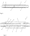
- the drawing shown shows a length compensator 1 according to the invention in a possible embodiment in longitudinal section.
- the length compensator 1 is used to record or compensate for the change in length of a pipeline, which is caused by temperature changes, for example.
- the length compensator 1 has two connection components 2 which are fastened between the opposite free ends of a pipeline.
- the two opposite end faces of the connection components 2 in the support tube 4 are connected to one another by means of a compensation element 3 at the compensation element ends 8, with alternative connection options also being conceivable.
- the connections are preferably inseparable and are produced, for example, by a material connection, such as welding or by means of an injection molding process, which ensures that the connection is tight.
- the ends of the compensating elements 8 are overmoulded and the connection components 2 are formed, although other types of connection are also conceivable, such as positive and/or non-positive connections, as in 3 shown.
- the compensating element 3 is surrounded by the support tube 4 and the connecting component 2 is at least partially surrounded by the support tube 4 . Because the compensating element 3 is suitably surrounded by the support tube 4, it serves to support it and absorbs the internal pressure that is generated by the medium. Due to the surrounding support tube 4, the compensating element 3 cannot expand radially. The compensating element 3 expands and contracts only in the axial direction, whereby the change in length of the pipeline is compensated for and the length compensator 1 nevertheless also withstands the required internal pressure according to the pipeline specification.
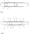
- an insulated length compensator 1 As a further embodiment shows 2 an insulated length compensator 1.
- the support tube 4 suitably encloses the compensating element 3 and that expansion and contraction are only possible in the axial direction.
- an insulation layer 5 is arranged on the outer circumference of the support tube 4. This possible embodiment is used in insulated pipeline systems and, in addition to the length compensation of the pipeline system, ensures rapid installation without subsequently attaching separate insulation to the length compensator.
- connection component 2 a possible connection from the length compensator 1 or the connection components 2 to the pipeline is also shown, whereby this can also be implemented for length compensators without an insulation layer.
- a coupling 6 is attached directly to a connection component 2, this being designed here as an electrofusion sleeve, but other couplings are also conceivable.
- the electrofusion socket is welded directly to the connection component 2 on one side and to the pipeline on the other side.
- the connection component 2 is welded to a connection piece 7 on the end face, preferably by means of WNF welding or another material connection technique. And this connecting piece 7 is then in turn connected to a coupling 6, here again an electrofusion sleeve 6.
- a length compensator 1 In 3 an alternative embodiment of a length compensator 1 is shown.
- the compensating element ends 8 are fastened to the connection components 2 by means of a positive and non-positive connection 9 .
- a clamp is used, but other known connection techniques can also be used for this purpose.
- connection component 2 which are connected as already mentioned via a material, positive and / or frictional connection.
- One of the connection components 2 is preferably fixed firmly to the support tube 4 or axially to the support tube 4, so that the length compensator 1 or the connection component 2 only moves axially on one side.
- the length compensator 1 has a stop element 11 on the opposite side of the connection component 2 fixed to the support tube 4 .
- the inner cylindrical hollow body 31 can be seen, which is preferably made of an elastic material, preferably a plastic.
- a spiral-shaped element 33 is arranged on its outer lateral surface 32, which forms a friction-reducing layer through its outer lateral surface in order to have the lowest possible resistance to the inner lateral surface of the support tube.
- the spiral-shaped element 33 is preferably made of a plastic.
- the latter has a profile 34 on its outer lateral surface 32 .
- the profiling 34 is preferably designed as a web running in a spiral shape along the outer lateral surface 32 of the cylindrical hollow body 31 .
- the cylindrical hollow body 31 preferably has an increase in wall thickness towards the end faces. This ensures a broader distribution of the tension that occurs when the train is pulled and ensures that there is a connection between the compensating element or the cylindrical hollow body 31 and the connection components 2 that can withstand higher loads. In 6 the cylindrical hollow body 31 is shown separately.
- the compensating element 3 can be produced by the separate production of the cylindrical hollow body 31 and the separate production of the spiral-shaped element 33 and subsequent assembly by mounting the spiral-shaped element 33 onto the cylindrical hollow body 31 or screwing it on or by a two-component injection molding, in which the cylindrical hollow body 31 and the spiral-shaped element 33 are pointed together and thus an assembly process of the two components can be saved.
- a material connection can also be created between the two components in addition to a positive and non-positive connection.
Landscapes
- Engineering & Computer Science (AREA)
- General Engineering & Computer Science (AREA)
- Mechanical Engineering (AREA)
- Rigid Pipes And Flexible Pipes (AREA)
- Lining Or Joining Of Plastics Or The Like (AREA)
- Thermal Insulation (AREA)
- Joints Allowing Movement (AREA)
- Axle Suspensions And Sidecars For Cycles (AREA)
- Undergarments, Swaddling Clothes, Handkerchiefs Or Underwear Materials (AREA)
- Forklifts And Lifting Vehicles (AREA)
- Moulds For Moulding Plastics Or The Like (AREA)
- Injection Moulding Of Plastics Or The Like (AREA)
Description
- Die Erfindung betrifft einen Längenkompensator für Rohrleitungen, vorzugsweise Kunststoffrohrleitungen beinhaltend zwei Anschlusskomponenten aus Kunststoff, ein Ausgleichselement aus einem elastischen Material und ein Stützrohr, wobei das Ausgleichselement zwischen den beiden Anschlusskomponenten angeordnet ist und die Ausgleichselementenden mit den Anschlusskomponenten verbunden sind.
- Längenkompensatoren dienen der Aufnahme bzw. der Kompensation der Längenveränderung einer installierten Rohrleitung durch beispielsweise Temperaturveränderungen oder äussere Einflüsse wie Kräfte durch Erdbeben Pumpenstösse usw.. Die Länge einer Rohrleitung verändert sich in Abhängigkeit der Temperatur, sei es aufgrund der Aussentemperatur oder der Mediumstemperatur des in der Rohrleitung transportierten Mediums. Diese Längenveränderung, sei es eine Ausdehnung oder ein Zusammenziehen, gilt es aufzunehmen. Aus dem Stand der Technik sind beispielsweise Rohrschlaufen bekannt, die durch ihre Umlenkungen der Rohrleitung eine gewisse Längenveränderung zulassen bzw. aufnehmen. Des Weiteren sind aus dem Stand der Technik auch Faltenbälge oder Gummimuffen wie auch axial ineinander verschiebbare Rohre bekannt.
- Das deutsche Gebrauchsmuster 7325208 offenbart einen Dehnungsausgleicher für Rohrleitungen, wobei der Dehnungskörper in einem Gehäuse angeordnet ist, das
- eine ovale Querschnittsform aufweist in der sich der Dehnungskörper entsprechend auch waagrecht bewegen kann.
- Das Dokument
US 2015/273756 A1 offenbart ein Verfahren zur Herstellung eines Dehnungskompensators, wobei das Verfahren umfasst: (a) das Bereitstellen einer inneren Kunststoffauskleidung mit einem ersten und einem zweiten Ende, die voneinander beabstandet sind, einer inneren Oberfläche, einer äußeren Oberfläche und einem Innenvolumen, das sich von dem ersten Ende zu dem zweiten Ende erstreckt; (b) das Positionieren der inneren Kunststoffauskleidung im Inneren einer länglichen Metallleitung, wobei die längliche Metallleitung ein erstes und ein zweites beabstandetes Ende, eine Innenfläche, eine Außenfläche und einen Expansions-/Kontraktionsabschnitt aufweist; (c) das Aufbringen von Druck auf ein Fluid, das sich in dem Innenvolumen der inneren Kunststoffauskleidung befindet, während die innere Kunststoffauskleidung bei oder über einer Formgebungstemperatur ist, um die innere Kunststoffauskleidung zu expandieren, wodurch die expandierte innere Kunststoffauskleidung einen Expansions-/Kontraktionsabschnitt aufweist; und (d) das Abkühlen der inneren Kunststoffauskleidung auf eine Temperatur unterhalb der Formgebungstemperatur. Der Dehnungskompensator kann mit einer Hülse versehen sein. Die Hülse kann den gesamten Dehnungs-/Kontraktionsabschnitt überdecken. Verbinder können an den gegenüberliegenden Enden des Metallrohrs und der Kunststoffauskleidung vorgesehen werden. Die Verbinder können durch Umspritzen von Teilen des Verbinders auf die Enden des Metallrohrs und der inneren Kunststoffauskleidung gebildet werden. Alternativ können Verbindungsabschnitte der Verbinder an die innere Kunststoffauskleidung z.B. durch Schweißen befestigt werden. - Die oben aufgeführten Lösungen bringen die Nachteile mit sich, dass sie einen hohen Platzbedarf benötigen, nur einen geringen Kompensationsweg aufweisen und/oder keinen hohen Innendruck zulassen bzw. nicht denselben Innendruck zulassen wie die Rohrleitung selbst.
- Es ist Aufgabe der Erfindung einen Längenkompensator für Rohrleitungen vorzuschlagen, der einen langen Kompensationsweg zulässt und demselben Innendruck stand hält wie die Rohrleitung selbst. Zudem soll die Aussenmantelfläche des Ausgleichselementes einen geringen Reibungswiderstand aufweisen um eine einfache Längenveränderung des Längenkompensators zu ermöglichen.
- Diese Aufgabe wird erfindungsgemäss durch einen Längenkompensator nach Anspruch 1 gelöst.
- Die Aussenmantelfläche des Ausgleichselementes ist am gesamten Umfang von der Innenmantelfläche des Stützrohres passend umfasst, wobei das Stützrohr eine runde Querschnittsfläche aufweist und das Ausgleichselement sich ausschliesslich in axialer Richtung ausdehnt und zusammenzieht.
- Die runde Querschnittsfläche des Stützrohres erstreckt sich vorzugsweise über die komplette Länge des Stützrohres, wobei die Querschnittsfläche vorzugsweise über die gesamte Länge konstant ist.
- Der erfindungsgemässe Längenkompensator für Rohrleitungen, vorzugsweise Kunststoffrohrleitungen, beinhaltet zwei Anschlusskomponenten aus Kunststoff. Die Anschlusskomponenten sind koaxial zueinander ausgerichtet und weisen vorzugsweise denselben Innen- und Aussendurchmesser auf. Des Weiteren weist der Längenkompensator ein Ausgleichselement aus einem elastischen Material aus einem thermoplastischem Elastomer (TPE) auf, wobei das Ausgleichselement durch einen einfachen elastischen Schlauch oder ein Rohr gebildet sein kann wie auch durch ein speziell dafür entwickeltes Element, das die Längenveränderung einer Rohrleitung aufnimmt. Der Längenkompensator weist ebenso ein Stützrohr auf indem das Ausgleichselement angeordnet ist. Das Ausgleichselement ist zwischen den beiden Anschlusskomponenten angeordnet. Das Ausgleichselement bzw. die Ausgleichselementenden sind mit den Anschlusskomponenten verbunden. Die Aussenmantelfläche des Ausgleichselementes ist am gesamten Umfang von der Innenmantelfläche des Stützrohres passend umfasst, das heisst, das Ausgleichselement ist vorzugsweise konzentrisch im Stützrohr angeordnet. Durch diese Anordnung und Formgestaltung des Ausgleichselements und des Stützrohres kann sich das Ausgleichselement ausschliesslich in axialer Richtung ausdehnen und zusammenziehen. Dadurch, dass das Stützrohr das Ausgleichselement bzw. dessen Umfang umgibt wird der Innendruck vom Stützrohr aufgenommen und das Ausgleichselement nicht überbeansprucht da es vom Stützrohr gestützt wird. Vorzugsweise sind auch die Anschlusskomponenten zumindest teilweise vom Stützrohr umfasst bzw. im Stützrohr angeordnet, dies dient der Führung der Anschlusskomponenten. Es ist vorteilhaft wenn auch die Anschlusskomponenten konzentrisch im oder am Stützrohr angeordnet sind.
- Vorzugsweise ist eine Anschlusskomponente axial am bzw. mit dem Stützrohr fixiert, wodurch die Längenveränderung durch die Verschiebung der anderen Anschlusskomponente und dem Zusammenziehen oder Ausdehnen des Ausgleichselements eingestellt wird.
- Vorzugsweise sind die Anschlusskomponenten aus Polyethylen (PE) hergestellt, aber auch Polypropylen (PP), Polybuten (PB), Polyvinylidenfluorid (PVDF), Polyvinylchlorid (PVC), Acrylnitril-Butadien-Styrol (ABS) oder Ethylene ChloroTriFluoroEthylene (ECTFE) sowie andere typische Rohrleitungswerkstoffe aus Kunststoff können eingesetzt werden.
- Erfindungsgemäss sind die Anschlusskomponenten mit dem jeweiligen Ausgleichselementende mittels einer stoffschlüssigen Verbindung und zwar mittels einer Stumpfschweissung, speziell bevorzugt mit einer WNF-Schweissung, einer Muffenschweissung, oder einer Elektromuffenschweissung verbunden. Wobei eine Schweissung mittels Kontaktschweissung wie auch einem berührungslosen Schweissverfahren vorzugsweise IR-Schweissen durchgeführt werden kann.
- Alternativ können erfindungsgemäss die Anschlusskomponenten und das Ausgleichselement im Zweikomponentenspritzgiessen miteinander verbunden werden und jeweils an den Ausgleichselementenden ist eine Anschlusskomponente mittels Kunststoffspritzgiessen angeform. Dies gewährleistet eine wirtschaftliche Herstellung des erfindungsgemässen Längenkompensators sowie auch die Dichtheit zwischen dem Ausgleichselement und den Anschlusskomponenten.
- Es ist vorteilhaft, wenn die jeweilige Stirnseite der Anschlusskomponenten mit dem jeweiligen Ausgleichselementende verbunden ist. Dies ermöglicht eine einfache, stabile und vor allem auch dichte Verbindung zwischen dem Ausgleichselement und der Anschlusskomponente.
- Zusätzlich besteht die Möglichkeit, dass die Anschlusskomponenten mit dem jeweiligen Ausgleichselementende mittels einer formschlüssigen und/oder kraftschlüssigen Verbindung verbunden sind.
- Vorzugsweise weist das Ausgleichselement denselben Innendurchmesser auf wie die Anschlusskomponenten, dies gewährleistet einen geringen Strömungswiderstand am Innendurchmesser was dem Medium und dem Minimieren von Verunreinigungen welche sich an hervorstehenden Kanten und Ecken ansammeln entgegenkommt. Gemäss einer bevorzugten Ausführungsform weist der erfindungsgemässe Längenkompensator eine reibungsreduzierende Schicht auf, vorzugsweise ist die reibungsreduzierende Schicht an der Aussenmantelfläche des Ausgleichselementes angeordnet. Dies gewährleistet einen geringen Widerstand, wodurch sich die Längenveränderung der Rohrleitung im Längenkompensator leicht einstellt bzw. dort aufgenommen wird. Zudem wird dadurch gewährleistet, dass der Längenkompensator den geringsten Widerstand in der Rohleitung darstellt und die Lageveränderung dort kompensiert wird damit sich die Rohrleitung nicht verbiegt oder sich sonst ungewollt verschiebt.
- Zudem ist es vorteilhaft wenn auch die Anschlusskomponenten an deren Aussenmantelfläche eine reibungsreduzierende Schicht aufweisen, analog den Schichten die beim Stützrohr oder Ausgleichselement angewandt werden.
- Vorzugsweise ist das Stützrohr aus einem Kunststoff hergestellt, speziell bevorzugt ist POM, PE-UHMW, PTFE, MoS2 Polyethylen (PE), Polypropylen (PP), Polybuten (PB), Polyvinylidenfluorid (PVDF), Polyvinylchlorid (PVC), Acrylnitril-Butadien-Styrol (ABS) oder Ethylene ChloroTriFluoroEthylene (ECTFE) diese Kunststoffe weisen gute Trockenschmiereigenschaften auf.
- Es hat sich als vorteilhaft gezeigt, wenn die reibungsreduzierende Schicht durch ein Fett oder Öl insbesondere PTFE oder Silikon gebildet ist. Dies ist einfach und schnell am Längenkompensator bzw. an der entsprechenden Mantelfläche aufzutragen und senkt den Reibungswiderstand zwischen Ausgleichselement und Stützrohr wesentlich.
- Als alternative Ausgestaltung hat sich gezeigt, wenn die reibungsreduzierende Schicht durch eine Trockenschmierung insbesondere einer Beschichtung der Innenmantelfläche des Stützrohres vorzugsweise durch einen Gleitlack oder eine Metallbeschichtung gebildet ist. Dies ermöglicht einen wartungsfreien Einsatz des Längenkompensators.
- Eine bevorzugte Ausführungsform des erfindungsgemässen Längenkompensators besteht darin, dass die reibungsreduzierende Schicht durch Ringe oder ein Gewebe gebildet ist, wobei die reibungsreduzierende Schicht die Aussenmantelfläche des Ausgleichselements bildet. Es ist vorteilhaft wenn die Ringe oder das Gewebe koaxial zum Ausgleichselement wie auch zum Stützrohr angeordnet sind und passend zwischen Ausgleichselement und Stützrohr liegt.
- Der erfindungsgemässe Längskompensator weist vorzugsweise ein Anschlagelement auf, wobei das Anschlagelement am einen Ende des Stützrohres angeordnet ist. Das Anschlagelement dient dazu, dass der Längenkompensator bzw. das Ausgleichselement nicht überdehnt wird und nur eine maximale Ausdehnung zugelassen ist. Obwohl das Ausgleichselement mit den Anschlusskomponenten dicht verbunden ist, weist das Anschlagselement vorzugsweise eine Dichtung auf die nochmals die Dichtheit des Langenkompensators gewährleistet und vor Schmutzeintrag von aussen schützt.
- Als weitere Ausgestaltungsmöglichkeit hat sich gezeigt, wenn das Stützrohr von einer Isolationsschicht umfasst ist. Dies bringt vor allem den Vorteil bei isolierten oder vorisolierten Rohrleitungssystemen, dass der in die Rohrleitung eingebaute Längenkompensator auch eine Isolationsschicht aufweist und nicht noch separat isoliert werden muss. Dadurch, dass das Stützrohr sich nicht verändert und die Kompensation sich im Inneren des Stützrohres abspielt kann am Aussenumfang des Stützrohres eine Isolationsschicht angebracht werden oder auch andere Schichten, Abdeckungen oder Befestigungen vorgesehen werden können.
- Ausführungsbeispiele der Erfindung werden anhand der Figuren beschrieben, wobei sich die Erfindung nicht nur auf die Ausführungsbeispiele beschränkt. Es zeigen:
- Fig. 1
- einen Längsschnitt durch einen erfindungsgemässen Längenkompensator mit stoffschlüssiger Verbindung an den Stirnseiten der Anschlusskomponenten,
- Fig. 2
- einen Längsschnitt durch einen erfindungsgemässen Längenkompensator mit Isolationsschicht,
- Fig. 3
- einen Längsschnitt durch einen nicht unter den Schutzumfang der Ansprüche fallenden Längenkompensator mit form- und kraftschlüssiger Verbindung zwischen Ausgleichselement und Anschlusskomponenten,
- Fig. 4
- einen Längsschnitt durch einen erfindungsgemässen Längenkompensator mit einem erfindungsgemässen Ausgleichselement,
- Fig. 5
- einen Längsschnitt eines Ausgleichselements für einen Längenkompensator und
- Fig. 6
- ein zylinderförmiger Hohlkörper eines Ausgleichselements.
- Die in
Fig. 1 dargestellte Zeichnung zeigt einen erfindungsgemässen Längenkompensator 1 in einer möglichen Ausführungsform im Längsschnitt. Der Längenkompensator 1 dient der Aufnahme bzw. dem Ausgleich der Längenveränderung einer Rohrleitung, welche durch beispielsweise Temperaturveränderungen entstehen. Der Längenkompensator 1 weist zwei Anschlusskomponenten 2 auf, die zwischen den sich gegenüberliegenden freien Enden einer Rohrleitung befestigt werden. Die beiden sich gegenüberliegenden Stirnseiten der Anschlusskomponenten 2 im Stützrohr 4 sind mittels eines Ausgleichselementes 3 an den Ausgleichselementenden 8 miteinander verbunden, wobei auch alternative Verbindungsmöglichkeiten denkbar sind. Die Verbindungen sind vorzugsweise untrennbar und werden beispielsweise durch einen Stoffschluss, wie einer Schweissung oder mittels Spritzgussverfahren hergestellt, das gewährleistet, dass die Verbindung dicht ist. - Beispielsweise durch Zweikomponentenspritzgiessen werden die Ausgleichselementenden 8 umspritzt und die Anschlusskomponenten 2 ausgebildet, wobei auch andere Verbindungsarten denkbar sind wie form- und/oder kraftschlüssige Verbindungen, wie in
Fig. 3 dargestellt. Das Ausgleichselement 3 wird vom Stützrohr 4 umgeben wie auch die Anschlusskomponente 2 zumindest teilweise vom Stützrohr 4 umgeben sind. Dadurch, dass das Ausgleichselement 3 vom Stützrohr 4 passend umgeben ist, dient es zu dessen Abstützung und nimmt den Innenduck auf, der durch das Medium erzeugt wird. Aufgrund des umgebenden Stützrohres 4 kann sich das Ausgleichselement 3 nicht radial ausdehnen. Das Ausgleichselement 3 dehnt wie auch zieht sich nur in axialer Richtung aus oder zusammen, wodurch die Längenveränderung der Rohrleitung ausgeglichen wird und dennoch auch der Längenkompensator 1 dem geforderten Innendruck gemäss Rohrleitungsspezifikation standhält. - Als eine weitere Ausführungsform zeigt
Fig. 2 einen isolierten Längenkompensator 1. Auch hier ist wiederum gut ersichtlich, dass das Stützrohr 4 den Ausgleichselement 3 passend umfasst und eine Ausdehnung wie ein Zusammenziehen nur in axialer Richtung möglich ist. In dieser abgebildeten Ausführungsform ist am Aussenumfang des Stützrohres 4 eine Isolationsschicht 5 angeordnet, diese mögliche Ausgestaltungsform wird bei isolierten Rohrleitungssystemen angewandt und gewährleistet neben der Längenkompensation des Rohrleitungssystems der rasche Einbau ohne nachträglich noch eine separate Isolierung am Längenkompensator anzubringen. - Zudem ist in
Fig. 2 auch eine mögliche Verbindung vom Längenkompensator 1 bzw. den Anschlusskomponenten 2 zur Rohrleitung aufgezeigt, wobei dies auch für Längenkompensatoren ohne Isolationsschicht so umsetzbar ist. Als Beispiel wird an einer Anschlusskomponente 2 direkt eine Kupplung 6 angebracht, wobei diese hier als Elektroschweissmuffe ausgebildet ist aber auch andere Kupplungen denkbar sind. Die Elektroschweissmuffe wird direkt auf der einen Seite mit der Anschlusskomponente 2 verschweisst und auf der anderen Seite mit der Rohrleitung. Als alternatives Beispiel ist auf der anderen Seite des Längenkompensators 1 die Anschlusskomponente 2 mit einem Anschlussstück 7 stirnseitig verschweisst, vorzugsweise mittels WNF-Schweissung oder eine andere stoffschlüssige Verbindungstechnik. Und dieses Anschlussstück 7 ist dann wiederum mit einer Kupplung 6, hier auch wieder eine Elektroschweissmuffe 6 verbunden. Dies ist nur eine beispielhafte Darstellung es gibt noch weitere Möglichkeiten wie die Anschlusskomponenten 2 mit der Rohrleitung verbunden werden kann. - In
Fig. 3 ist eine alternative Ausführungsform eines Längenkompensators 1 dargestellt. Bei der dargestellten Ausführung sind die Ausgleichselementenden 8 mittels einer form- und kraftschlüssigen Verbindung 9 an den Anschlusskomponenten 2 befestigt. Wobei dazu inFig. 3 eine Klemmung verwendet wird, jedoch können dazu auch andere bekannte Verbindungstechniken eingesetzt werden. -
Fig. 4 zeigt einen erfindungsgemässen Längenkompensator 1 mit einem erfindungsgemässen Ausgleichselement 3. Der Längenkompensator 1 weist wie auch bei den anderen Ausführungsformen in denen ein blosser Schlauch als Ausgleichselement eingesetzt wird, an den beiden Ausgleichselementenden 8 jeweils eine Anschlusskomponente 2 auf, die wie bereits erwähnt über einen Stoff-, Form- und/oder Kraftschluss verbunden sind. Vorzugsweise ist eine der Anschlusskomponenten 2 fest mit dem Stützrohr 4 bzw. axial mit dem Stützrohr 4 fixiert, so dass sich der Längenkompensator 1 bzw. die Anschlusskomponente 2 nur auf einer Seite axial verschiebt. Um die axiale Ausdehnung zu begrenzen, weist der Längenkompensator 1 auf der gegenüberliegenden Seite der am Stützrohr 4 fixierten Anschlusskomponente 2 ein Anschlagselement 11 auf. - In
Fig. 5 ist das Ausgleichselement 3 separat dargestellt. Ersichtlich ist der innenliegende zylinderförmige Hohlkörper 31, welcher vorzugsweise aus einem elastischen Material vorzugsweise einem Kunststoff hergestellt ist. An dessen äusserer Mantelfläche 32 ist ein spiralförmiges Element 33 angeordnet, welches durch seine äussere Mantelfläche eine reibreduzierende Schicht, um einen möglichst geringen Widerstand gegenüber der inneren Mantelfläche des Stützrohres aufzuweisen, bildet. Das spiralförmige Element 33 ist vorzugsweise aus einem Kunststoff hergestellt. Zur definierten Anordnung auf dem innenliegenden zylinderförmigen Hohlkörper 31 weist dieser an dessen äusserer Mantelfläche 32 eine Profilierung 34 auf. Dadurch kann sich das spiralförmige Element 33, welches zwischen der Profilierung angeordnet ist in seiner Anordnung nicht verschieben und es ist eine gleichmässige Ausdehnung des Ausgleichselements 3 gewährleistet. Die Profilierung 34 ist vorzugsweise als spiralförmig verlaufender Steg entlang der äusseren Mantelfläche 32 des zylinderförmigen Hohlkörpers 31 ausgebildet. - Vorzugsweise weist der zylinderförmige Hohlkörper 31 gegen die Stirnflächen hin eine Wandstärkenzunahme auf. Dies gewährleistet eine breitere Verteilung der bei Zug auftretenden Spannung und sorgt dafür, dass eine höher belastbare Verbindung zwischen dem Ausgleichselement bzw. dem zylinderförmigen Hohlkörper 31 und den Anschlusskomponenten 2 besteht. In
Fig. 6 ist der zylinderförmige Hohlkörper 31 separat dargestellt. - Das Ausgleichselement 3 kann durch die separate Herstellung des zylinderförmigen Hohlkörpers 31 und die separate Herstellung des spiralförmigen Elements 33 und eine anschliessende Montage, indem das spiralförmige Element 33 auf den zylinderförmigen Hohlkörper 31 montiert bzw. aufgeschraubt wird hergestellt werden oder aber durch ein Zweikomponentenspritzgiessen, indem der zylinderförmige Hohlkörper 31 und das spiralförmige Element 33 zusammen gespitzt werden und dadurch ein Montagevorgang der beiden Komponenten eingespart werden kann. Durch das Herstellen im Zweikomponentenspritzgussverfahren kann auch zwischen den beiden Komponenten neben einem Form- und Kraftschluss auch ein Stoffschluss entstehen.
-
- 1
- Längenkompensator
- 2
- Anschlusskomponente
- 3
- Ausgleichselement
- 4
- Stützrohr
- 5
- Isolationsschicht
- 6
- Kupplung / Elektroschweissmuffe
- 7
- Anschlussstück
- 8
- Ausgleichselementende
- 9
- Form- und/oder kraftschlüssige Verbindung
- 10
- Aussenmantelfläche Ausgleichselement
- 11
- Anschlagelement
- 31
- Zylinderförmiger Hohlkörper
- 32
- Äussere Mantelfläche des zylinderförmigen Hohlkörpers
- 33
- Spiralförmiges Element
- 34
- Profilierung / spiralförmig verlaufender Steg
Claims (7)
- Längenkompensator (1) für Rohrleitungen, vorzugsweiseKunststoffrohrleitungen, beinhaltend zwei Anschlusskomponenten (2) ausKunststoff, ein Ausgleichselement (3) aus einem elastischem Material aus einem thermoplastischem Elastomer (TPE), und ein Stützrohr (4), wobei das Ausgleichselement (3) zwischen den beiden Anschlusskomponenten (2) angeordnet ist und die Ausgleichselementenden (8) mit den Anschlusskomponenten (2) verbunden sind, wobei die Aussenmantelfläche des Ausgleichselementes (3) am gesamten Umfang von der Innenmantelfläche des Stützrohres (4) passend umfasst ist, wobei das Stützrohr (4) eine runde Querschnittsfläche aufweist und das Ausgleichselement (3) sich ausschliesslich in axialer Richtung ausdehnt und zusammenzieht,wobei die Anschlusskomponenten (2) mit dem jeweiligen Ausgleichselementende (8) mittels einer stoffschlüssigen Verbindung und zwar mittels einer Stumpfschweissung, speziell bevorzugt mit einer WNF-Schweissung, einer Muffenschweissung, oder einer Elektromuffenschweissung verbunden ist,oderwobei die Anschlusskomponenten (2) und das Ausgleichselement im Zweikomponentenspritzgiessen miteinander verbunden werden und jeweils an den Enden des Ausgleichselements (3) eine Anschlusskomponente angespritzt ist.
- Längenkompensator (1) nach Anspruch 1, dadurch
gekennzeichnet, dass die Anschlusskomponenten (2) mit dem jeweiligen Ausgleichselementende (8) mittels einer formschlüssigen und/oder kraftschlüssigen Verbindung verbunden sind. - Längenkompensator (1) nach einem der vorangehenden Ansprüche, dadurch gekennzeichnet, dass eine reibungsreduzierende Schicht an der Aussenmantelfläche des Ausgleichselements (3) angeordnet ist, vorzugsweise ist die reibungsreduzierende Schicht durch ein Fett oder Öl insbesondere PTFE oder Silikon gebildet.
- Längenkompensator (1) nach Anspruch 3, dadurch gekennzeichnet, dass die reibungsreduzierende Schicht durch eine Trockenschmierung insbesondere einer Beschichtung der Innenmantelfläche des Stützrohres (4) vorzugsweise durch einen Gleitlack oder eine Metallbeschichtung gebildet ist.
- Längenkompensator nach einem der Ansprüche 3 oder 4,
dadurch
gekennzeichnet, dass die reibungsreduzierende Schicht durch Ringe oder ein Gewebe gebildet ist, wobei die reibungsreduzierende Schicht die Aussenmantelfläche des Ausgleichselements bildet. - Längenkompensator (1) nach einem der Ansprüche 1 bis 5, dadurch gekennzeichnet, dass die der Längenkompensator (1) ein Anschlagelement (11) aufweist, wobei das Anschlagelement (11) am einen Ende des Stützrohres (4) angeordnet ist.
- Längenkompensator (1) nach einem der Ansprüche 1 bis 6, dadurch gekennzeichnet, dass das Stützrohr (4) von einer Isolationsschicht umfasst ist.
Priority Applications (5)
| Application Number | Priority Date | Filing Date | Title |
|---|---|---|---|
| CA3063648A CA3063648A1 (en) | 2018-12-13 | 2019-12-03 | Length compensator |
| KR1020190160508A KR20200074007A (ko) | 2018-12-13 | 2019-12-05 | 길이 보상기 |
| JP2019223629A JP7479140B2 (ja) | 2018-12-13 | 2019-12-11 | 長さ補償器 |
| US16/710,749 US11598469B2 (en) | 2018-12-13 | 2019-12-11 | Length compensator |
| CN201911285600.6A CN111322482B (zh) | 2018-12-13 | 2019-12-13 | 长度补偿器 |
Applications Claiming Priority (1)
| Application Number | Priority Date | Filing Date | Title |
|---|---|---|---|
| EP18212137 | 2018-12-13 |
Publications (2)
| Publication Number | Publication Date |
|---|---|
| EP3667148A1 EP3667148A1 (de) | 2020-06-17 |
| EP3667148B1 true EP3667148B1 (de) | 2022-10-19 |
Family
ID=64665232
Family Applications (1)
| Application Number | Title | Priority Date | Filing Date |
|---|---|---|---|
| EP19163711.5A Active EP3667148B1 (de) | 2018-12-13 | 2019-03-19 | Längenkompensator |
Country Status (11)
| Country | Link |
|---|---|
| US (1) | US11598469B2 (de) |
| EP (1) | EP3667148B1 (de) |
| JP (1) | JP7479140B2 (de) |
| KR (1) | KR20200074007A (de) |
| CN (1) | CN111322482B (de) |
| CA (1) | CA3063648A1 (de) |
| DK (1) | DK3667148T3 (de) |
| ES (1) | ES2930261T3 (de) |
| FI (1) | FI3667148T3 (de) |
| PL (1) | PL3667148T3 (de) |
| PT (1) | PT3667148T (de) |
Families Citing this family (2)
| Publication number | Priority date | Publication date | Assignee | Title |
|---|---|---|---|---|
| CN112483757B (zh) * | 2020-12-11 | 2022-09-16 | 焦作万瑞工贸有限公司 | 一种波纹管补偿器 |
| CN114001215B (zh) * | 2021-12-30 | 2022-04-08 | 中国空气动力研究与发展中心设备设计与测试技术研究所 | 一种隔振密封装置 |
Family Cites Families (31)
| Publication number | Priority date | Publication date | Assignee | Title |
|---|---|---|---|---|
| GB1246055A (en) * | 1969-05-20 | 1971-09-15 | Hepworth Iron Co Ltd | Improvements in or relating to pipe couplings |
| DE7325208U (de) * | 1973-07-09 | 1973-10-25 | Ahlborn E Ag | Dehnungsausgleicher für Rohrleitungen |
| FR2287005A1 (fr) * | 1974-10-01 | 1976-04-30 | Scient Tech Batimen Centre | Manchon de dilatation pour tubes |
| AT353067B (de) * | 1978-04-10 | 1979-10-25 | Straub Immanuel | Rohrkupplung zum verbinden von laengenaenderungen unterworfenen rohren |
| US4225143A (en) * | 1978-06-19 | 1980-09-30 | Advanced Thermal Systems, Inc. | Guided expansion joint |
| JPS57160485U (de) * | 1981-03-23 | 1982-10-08 | ||
| JPS59125690U (ja) * | 1983-02-14 | 1984-08-24 | 石川島播磨重工業株式会社 | 低温真空二重管 |
| DE3611208A1 (de) * | 1986-04-04 | 1987-10-08 | Haefele Carl Heinz | Leitungskompensator |
| DE29701625U1 (de) * | 1997-01-31 | 1997-03-20 | Witzenmann GmbH Metallschlauch-Fabrik Pforzheim, 75175 Pforzheim | Flexibles Leitungselement für Abgasleitungen |
| DE19706191A1 (de) * | 1997-02-18 | 1998-08-20 | Witzenmann Metallschlauchfab | Gelenkiges Verbindungselement für Rohrteile |
| CN2491487Y (zh) * | 2001-08-29 | 2002-05-15 | 宁波波尔新型建材开发有限公司 | 膨胀补偿器 |
| CN2748742Y (zh) * | 2004-12-02 | 2005-12-28 | 赵铎 | 埋地可维护套筒补偿器 |
| JP2006292095A (ja) * | 2005-04-12 | 2006-10-26 | Toyo Tire & Rubber Co Ltd | 高圧ゴムホース |
| EP1741968A1 (de) * | 2005-07-08 | 2007-01-10 | Uponor Innovation Ab | Spannring |
| DE102007043944A1 (de) * | 2007-09-14 | 2009-03-19 | Westfalia Metallschlauchtechnik Gmbh & Co. Kg | Flexibles Leitungselement mit kombinierter Wärmeisolation und Schwingungsdämpfung |
| CN201723898U (zh) * | 2010-02-10 | 2011-01-26 | 陈墅庚 | 复合型双向补偿器 |
| CN201851831U (zh) * | 2010-11-17 | 2011-06-01 | 陈墅庚 | 新型管道用耐腐蚀伸缩器 |
| US9435473B2 (en) * | 2011-05-04 | 2016-09-06 | Thomas & Betts International, Llc | Non-metallic expansion/deflection coupling modules |
| NL2010032C2 (nl) * | 2012-12-20 | 2014-06-23 | Trelleborg Ede B V | Expansievat. |
| US9976469B2 (en) * | 2013-07-15 | 2018-05-22 | Thermal Structures, Inc. | Flexible insulation device |
| EP2829782B1 (de) | 2013-07-23 | 2018-04-04 | Georg Fischer Rohrleitungssysteme AG | Sattel für einen Abzweigungsanschluss |
| US10046510B2 (en) * | 2014-03-25 | 2018-08-14 | Omachron Intellectual Property Inc. | Methods of manufacturing an expansion compensator |
| CA2855326A1 (en) * | 2014-06-26 | 2015-12-26 | G.B.D. Corp. | Method of installing an expansion compensator |
| CN107532755A (zh) * | 2015-05-28 | 2018-01-02 | 三菱电机株式会社 | 柔性管 |
| US10267447B2 (en) * | 2015-08-12 | 2019-04-23 | Harris Corporation | Fluid pipe assembly including length compensator and related methods |
| CN105090666A (zh) * | 2015-08-25 | 2015-11-25 | 江苏华能输送设备有限公司 | 直管压力平衡型双向补偿波纹补偿器 |
| EP3213890A1 (de) | 2016-03-01 | 2017-09-06 | Georg Fischer Rohrleitungssysteme AG | Schäl- und schneidwerkzeug |
| EP3470186B1 (de) | 2017-10-11 | 2024-06-19 | Georg Fischer Rohrleitungssysteme AG | Verfahren und vorrichtung zum abisolieren von vorisolierten rohrleitungen |
| EP3550291A1 (de) | 2018-04-05 | 2019-10-09 | Georg Fischer Rohrleitungssysteme AG | Befestigungsvorrichtung für messgeräte an rohren |
| EP3550256B1 (de) | 2018-04-05 | 2021-03-10 | Georg Fischer Rohrleitungssysteme AG | Erkennung einer schweissnahtgeometrie |
| CN108869934A (zh) * | 2018-06-20 | 2018-11-23 | 朱海军 | 金属软管补偿器的软管结构 |
-
2019
- 2019-03-19 DK DK19163711.5T patent/DK3667148T3/da active
- 2019-03-19 PT PT191637115T patent/PT3667148T/pt unknown
- 2019-03-19 FI FIEP19163711.5T patent/FI3667148T3/fi active
- 2019-03-19 ES ES19163711T patent/ES2930261T3/es active Active
- 2019-03-19 PL PL19163711.5T patent/PL3667148T3/pl unknown
- 2019-03-19 EP EP19163711.5A patent/EP3667148B1/de active Active
- 2019-12-03 CA CA3063648A patent/CA3063648A1/en active Pending
- 2019-12-05 KR KR1020190160508A patent/KR20200074007A/ko active IP Right Grant
- 2019-12-11 JP JP2019223629A patent/JP7479140B2/ja active Active
- 2019-12-11 US US16/710,749 patent/US11598469B2/en active Active
- 2019-12-13 CN CN201911285600.6A patent/CN111322482B/zh active Active
Also Published As
| Publication number | Publication date |
|---|---|
| KR20200074007A (ko) | 2020-06-24 |
| PT3667148T (pt) | 2022-11-03 |
| CN111322482A (zh) | 2020-06-23 |
| CN111322482B (zh) | 2023-03-10 |
| ES2930261T3 (es) | 2022-12-09 |
| EP3667148A1 (de) | 2020-06-17 |
| JP2020094692A (ja) | 2020-06-18 |
| FI3667148T3 (fi) | 2023-01-31 |
| JP7479140B2 (ja) | 2024-05-08 |
| DK3667148T3 (da) | 2022-11-28 |
| US20200191304A1 (en) | 2020-06-18 |
| PL3667148T3 (pl) | 2023-02-20 |
| US11598469B2 (en) | 2023-03-07 |
| CA3063648A1 (en) | 2020-06-13 |
Similar Documents
| Publication | Publication Date | Title |
|---|---|---|
| DE3808383A1 (de) | Leitungsverbindung | |
| WO2013189740A2 (de) | Klemmverbindung für rohre | |
| DE1910512A1 (de) | Druckspeicher | |
| EP0152753A2 (de) | Flanschverbindung für faserverstärkte Kunststoffrohrteile | |
| EP2893241B1 (de) | Fitting, system mit einem solchen fitting und dichte verbindung mit einem solchen fitting | |
| EP1726865A2 (de) | Verbindungsanordnung mit Endabschnitten zweier zu verbindender Fluidleitungen | |
| EP3667148B1 (de) | Längenkompensator | |
| EP2933542A1 (de) | Anschlussverbindung für wellrohre | |
| EP3244119B1 (de) | Dichtungselement | |
| DE102010016972A1 (de) | Anschlussverbindung für ein Rohr | |
| EP3404305B1 (de) | Verbindungsanordnung für fluidleitungen | |
| EP1887271B1 (de) | Dichtring | |
| EP2295842B1 (de) | Rohverbinder zum dichten Verbinden an ein Rohrende eines Rohres aus nachgiebigem Werkstoff | |
| WO2021122020A1 (de) | Steckverbinderanordnung | |
| DE102011015462B4 (de) | Verfahren zur Herstellung eines Formteils | |
| EP0926417A2 (de) | Rohrpresskupplung für Wellrohre | |
| EP3894733A1 (de) | Dichtungsanordnung, dichtmuffe und deren verwendung | |
| EP1921364A1 (de) | Klemmfitting für ein Rohr, insbesondere Heizungs- und/oder Sanitärrohr | |
| DE3921174C2 (de) | ||
| EP3803178A1 (de) | Fluidverbindungsadapter, fluidverbindungsanordnung sowie verfahren zum herstellen einer fluidverbindungsanordnung | |
| DE102016007834A1 (de) | Leitungsverbindungsstruktur | |
| CH696082A5 (de) | Verbindungselement für die Verbindung zweier Rohrenden, insbesondere zweier Abwasserrohre. | |
| DE102018132078B4 (de) | Wellschlauch | |
| DE102016116652A1 (de) | Hybridfitting zum Anschluss an ein Ende eines Rohres | |
| DE202021104281U1 (de) | Abdeckvorrichtung zum Abdecken einer Verbindungsstelle von medienführenden Rohrendabschnitten |
Legal Events
| Date | Code | Title | Description |
|---|---|---|---|
| PUAI | Public reference made under article 153(3) epc to a published international application that has entered the european phase |
Free format text: ORIGINAL CODE: 0009012 |
|
| STAA | Information on the status of an ep patent application or granted ep patent |
Free format text: STATUS: THE APPLICATION HAS BEEN PUBLISHED |
|
| AK | Designated contracting states |
Kind code of ref document: A1 Designated state(s): AL AT BE BG CH CY CZ DE DK EE ES FI FR GB GR HR HU IE IS IT LI LT LU LV MC MK MT NL NO PL PT RO RS SE SI SK SM TR |
|
| AX | Request for extension of the european patent |
Extension state: BA ME |
|
| STAA | Information on the status of an ep patent application or granted ep patent |
Free format text: STATUS: REQUEST FOR EXAMINATION WAS MADE |
|
| 17P | Request for examination filed |
Effective date: 20201127 |
|
| RBV | Designated contracting states (corrected) |
Designated state(s): AL AT BE BG CH CY CZ DE DK EE ES FI FR GB GR HR HU IE IS IT LI LT LU LV MC MK MT NL NO PL PT RO RS SE SI SK SM TR |
|
| GRAP | Despatch of communication of intention to grant a patent |
Free format text: ORIGINAL CODE: EPIDOSNIGR1 |
|
| STAA | Information on the status of an ep patent application or granted ep patent |
Free format text: STATUS: GRANT OF PATENT IS INTENDED |
|
| INTG | Intention to grant announced |
Effective date: 20220513 |
|
| GRAS | Grant fee paid |
Free format text: ORIGINAL CODE: EPIDOSNIGR3 |
|
| GRAA | (expected) grant |
Free format text: ORIGINAL CODE: 0009210 |
|
| STAA | Information on the status of an ep patent application or granted ep patent |
Free format text: STATUS: THE PATENT HAS BEEN GRANTED |
|
| AK | Designated contracting states |
Kind code of ref document: B1 Designated state(s): AL AT BE BG CH CY CZ DE DK EE ES FI FR GB GR HR HU IE IS IT LI LT LU LV MC MK MT NL NO PL PT RO RS SE SI SK SM TR |
|
| REG | Reference to a national code |
Ref country code: GB Ref legal event code: FG4D Free format text: NOT ENGLISH |
|
| REG | Reference to a national code |
Ref country code: CH Ref legal event code: EP |
|
| REG | Reference to a national code |
Ref country code: PT Ref legal event code: SC4A Ref document number: 3667148 Country of ref document: PT Date of ref document: 20221103 Kind code of ref document: T Free format text: AVAILABILITY OF NATIONAL TRANSLATION Effective date: 20221027 |
|
| REG | Reference to a national code |
Ref country code: IE Ref legal event code: FG4D Free format text: LANGUAGE OF EP DOCUMENT: GERMAN |
|
| REG | Reference to a national code |
Ref country code: DE Ref legal event code: R096 Ref document number: 502019005945 Country of ref document: DE |
|
| REG | Reference to a national code |
Ref country code: AT Ref legal event code: REF Ref document number: 1525742 Country of ref document: AT Kind code of ref document: T Effective date: 20221115 |
|
| REG | Reference to a national code |
Ref country code: SE Ref legal event code: TRGR |
|
| REG | Reference to a national code |
Ref country code: DK Ref legal event code: T3 Effective date: 20221123 |
|
| REG | Reference to a national code |
Ref country code: NL Ref legal event code: FP |
|
| REG | Reference to a national code |
Ref country code: ES Ref legal event code: FG2A Ref document number: 2930261 Country of ref document: ES Kind code of ref document: T3 Effective date: 20221209 |
|
| REG | Reference to a national code |
Ref country code: NO Ref legal event code: T2 Effective date: 20221019 |
|
| REG | Reference to a national code |
Ref country code: FI Ref legal event code: FGE |
|
| REG | Reference to a national code |
Ref country code: LT Ref legal event code: MG9D |
|
| PG25 | Lapsed in a contracting state [announced via postgrant information from national office to epo] |
Ref country code: LT Free format text: LAPSE BECAUSE OF FAILURE TO SUBMIT A TRANSLATION OF THE DESCRIPTION OR TO PAY THE FEE WITHIN THE PRESCRIBED TIME-LIMIT Effective date: 20221019 |
|
| PG25 | Lapsed in a contracting state [announced via postgrant information from national office to epo] |
Ref country code: RS Free format text: LAPSE BECAUSE OF FAILURE TO SUBMIT A TRANSLATION OF THE DESCRIPTION OR TO PAY THE FEE WITHIN THE PRESCRIBED TIME-LIMIT Effective date: 20221019 Ref country code: LV Free format text: LAPSE BECAUSE OF FAILURE TO SUBMIT A TRANSLATION OF THE DESCRIPTION OR TO PAY THE FEE WITHIN THE PRESCRIBED TIME-LIMIT Effective date: 20221019 Ref country code: IS Free format text: LAPSE BECAUSE OF FAILURE TO SUBMIT A TRANSLATION OF THE DESCRIPTION OR TO PAY THE FEE WITHIN THE PRESCRIBED TIME-LIMIT Effective date: 20230219 Ref country code: HR Free format text: LAPSE BECAUSE OF FAILURE TO SUBMIT A TRANSLATION OF THE DESCRIPTION OR TO PAY THE FEE WITHIN THE PRESCRIBED TIME-LIMIT Effective date: 20221019 Ref country code: GR Free format text: LAPSE BECAUSE OF FAILURE TO SUBMIT A TRANSLATION OF THE DESCRIPTION OR TO PAY THE FEE WITHIN THE PRESCRIBED TIME-LIMIT Effective date: 20230120 |
|
| P01 | Opt-out of the competence of the unified patent court (upc) registered |
Effective date: 20230529 |
|
| REG | Reference to a national code |
Ref country code: DE Ref legal event code: R097 Ref document number: 502019005945 Country of ref document: DE |
|
| PG25 | Lapsed in a contracting state [announced via postgrant information from national office to epo] |
Ref country code: SM Free format text: LAPSE BECAUSE OF FAILURE TO SUBMIT A TRANSLATION OF THE DESCRIPTION OR TO PAY THE FEE WITHIN THE PRESCRIBED TIME-LIMIT Effective date: 20221019 Ref country code: RO Free format text: LAPSE BECAUSE OF FAILURE TO SUBMIT A TRANSLATION OF THE DESCRIPTION OR TO PAY THE FEE WITHIN THE PRESCRIBED TIME-LIMIT Effective date: 20221019 Ref country code: EE Free format text: LAPSE BECAUSE OF FAILURE TO SUBMIT A TRANSLATION OF THE DESCRIPTION OR TO PAY THE FEE WITHIN THE PRESCRIBED TIME-LIMIT Effective date: 20221019 Ref country code: CZ Free format text: LAPSE BECAUSE OF FAILURE TO SUBMIT A TRANSLATION OF THE DESCRIPTION OR TO PAY THE FEE WITHIN THE PRESCRIBED TIME-LIMIT Effective date: 20221019 |
|
| PLBE | No opposition filed within time limit |
Free format text: ORIGINAL CODE: 0009261 |
|
| STAA | Information on the status of an ep patent application or granted ep patent |
Free format text: STATUS: NO OPPOSITION FILED WITHIN TIME LIMIT |
|
| PG25 | Lapsed in a contracting state [announced via postgrant information from national office to epo] |
Ref country code: SK Free format text: LAPSE BECAUSE OF FAILURE TO SUBMIT A TRANSLATION OF THE DESCRIPTION OR TO PAY THE FEE WITHIN THE PRESCRIBED TIME-LIMIT Effective date: 20221019 Ref country code: AL Free format text: LAPSE BECAUSE OF FAILURE TO SUBMIT A TRANSLATION OF THE DESCRIPTION OR TO PAY THE FEE WITHIN THE PRESCRIBED TIME-LIMIT Effective date: 20221019 |
|
| 26N | No opposition filed |
Effective date: 20230720 |
|
| PG25 | Lapsed in a contracting state [announced via postgrant information from national office to epo] |
Ref country code: MC Free format text: LAPSE BECAUSE OF FAILURE TO SUBMIT A TRANSLATION OF THE DESCRIPTION OR TO PAY THE FEE WITHIN THE PRESCRIBED TIME-LIMIT Effective date: 20221019 |
|
| PG25 | Lapsed in a contracting state [announced via postgrant information from national office to epo] |
Ref country code: SI Free format text: LAPSE BECAUSE OF FAILURE TO SUBMIT A TRANSLATION OF THE DESCRIPTION OR TO PAY THE FEE WITHIN THE PRESCRIBED TIME-LIMIT Effective date: 20221019 |
|
| PG25 | Lapsed in a contracting state [announced via postgrant information from national office to epo] |
Ref country code: LU Free format text: LAPSE BECAUSE OF NON-PAYMENT OF DUE FEES Effective date: 20230319 |
|
| PGFP | Annual fee paid to national office [announced via postgrant information from national office to epo] |
Ref country code: IE Payment date: 20240321 Year of fee payment: 6 Ref country code: NL Payment date: 20240320 Year of fee payment: 6 |
|
| PGFP | Annual fee paid to national office [announced via postgrant information from national office to epo] |
Ref country code: AT Payment date: 20240321 Year of fee payment: 6 |
|
| PGFP | Annual fee paid to national office [announced via postgrant information from national office to epo] |
Ref country code: FI Payment date: 20240320 Year of fee payment: 6 Ref country code: DE Payment date: 20240320 Year of fee payment: 6 Ref country code: GB Payment date: 20240321 Year of fee payment: 6 Ref country code: PT Payment date: 20240307 Year of fee payment: 6 |
|
| PGFP | Annual fee paid to national office [announced via postgrant information from national office to epo] |
Ref country code: SE Payment date: 20240320 Year of fee payment: 6 Ref country code: PL Payment date: 20240307 Year of fee payment: 6 Ref country code: NO Payment date: 20240322 Year of fee payment: 6 Ref country code: IT Payment date: 20240329 Year of fee payment: 6 Ref country code: FR Payment date: 20240328 Year of fee payment: 6 Ref country code: DK Payment date: 20240326 Year of fee payment: 6 Ref country code: BE Payment date: 20240320 Year of fee payment: 6 |
|
| PGFP | Annual fee paid to national office [announced via postgrant information from national office to epo] |
Ref country code: CH Payment date: 20240401 Year of fee payment: 6 |
|
| PGFP | Annual fee paid to national office [announced via postgrant information from national office to epo] |
Ref country code: ES Payment date: 20240429 Year of fee payment: 6 |