EP3667128B1 - Parksperre zum feststellen eines getriebes sowie verfahren zur herstellung einer parksperre - Google Patents
Parksperre zum feststellen eines getriebes sowie verfahren zur herstellung einer parksperre Download PDFInfo
- Publication number
- EP3667128B1 EP3667128B1 EP19158621.3A EP19158621A EP3667128B1 EP 3667128 B1 EP3667128 B1 EP 3667128B1 EP 19158621 A EP19158621 A EP 19158621A EP 3667128 B1 EP3667128 B1 EP 3667128B1
- Authority
- EP
- European Patent Office
- Prior art keywords
- piston
- housing
- actuator
- parking lock
- longitudinal axis
- Prior art date
- Legal status (The legal status is an assumption and is not a legal conclusion. Google has not performed a legal analysis and makes no representation as to the accuracy of the status listed.)
- Active
Links
Images

Classifications
-
- F—MECHANICAL ENGINEERING; LIGHTING; HEATING; WEAPONS; BLASTING
- F16—ENGINEERING ELEMENTS AND UNITS; GENERAL MEASURES FOR PRODUCING AND MAINTAINING EFFECTIVE FUNCTIONING OF MACHINES OR INSTALLATIONS; THERMAL INSULATION IN GENERAL
- F16H—GEARING
- F16H57/00—General details of gearing
- F16H57/02—Gearboxes; Mounting gearing therein
- F16H57/032—Gearboxes; Mounting gearing therein characterised by the materials used
-
- B—PERFORMING OPERATIONS; TRANSPORTING
- B60—VEHICLES IN GENERAL
- B60T—VEHICLE BRAKE CONTROL SYSTEMS OR PARTS THEREOF; BRAKE CONTROL SYSTEMS OR PARTS THEREOF, IN GENERAL; ARRANGEMENT OF BRAKING ELEMENTS ON VEHICLES IN GENERAL; PORTABLE DEVICES FOR PREVENTING UNWANTED MOVEMENT OF VEHICLES; VEHICLE MODIFICATIONS TO FACILITATE COOLING OF BRAKES
- B60T1/00—Arrangements of braking elements, i.e. of those parts where braking effect occurs specially for vehicles
- B60T1/005—Arrangements of braking elements, i.e. of those parts where braking effect occurs specially for vehicles by locking of wheel or transmission rotation
-
- B—PERFORMING OPERATIONS; TRANSPORTING
- B60—VEHICLES IN GENERAL
- B60T—VEHICLE BRAKE CONTROL SYSTEMS OR PARTS THEREOF; BRAKE CONTROL SYSTEMS OR PARTS THEREOF, IN GENERAL; ARRANGEMENT OF BRAKING ELEMENTS ON VEHICLES IN GENERAL; PORTABLE DEVICES FOR PREVENTING UNWANTED MOVEMENT OF VEHICLES; VEHICLE MODIFICATIONS TO FACILITATE COOLING OF BRAKES
- B60T13/00—Transmitting braking action from initiating means to ultimate brake actuator with power assistance or drive; Brake systems incorporating such transmitting means, e.g. air-pressure brake systems
- B60T13/74—Transmitting braking action from initiating means to ultimate brake actuator with power assistance or drive; Brake systems incorporating such transmitting means, e.g. air-pressure brake systems with electrical assistance or drive
- B60T13/741—Transmitting braking action from initiating means to ultimate brake actuator with power assistance or drive; Brake systems incorporating such transmitting means, e.g. air-pressure brake systems with electrical assistance or drive acting on an ultimate actuator
- B60T13/743—Transmitting braking action from initiating means to ultimate brake actuator with power assistance or drive; Brake systems incorporating such transmitting means, e.g. air-pressure brake systems with electrical assistance or drive acting on an ultimate actuator with a spring accumulator
-
- F—MECHANICAL ENGINEERING; LIGHTING; HEATING; WEAPONS; BLASTING
- F16—ENGINEERING ELEMENTS AND UNITS; GENERAL MEASURES FOR PRODUCING AND MAINTAINING EFFECTIVE FUNCTIONING OF MACHINES OR INSTALLATIONS; THERMAL INSULATION IN GENERAL
- F16H—GEARING
- F16H63/00—Control outputs from the control unit to change-speed- or reversing-gearings for conveying rotary motion or to other devices than the final output mechanism
- F16H63/02—Final output mechanisms therefor; Actuating means for the final output mechanisms
- F16H63/30—Constructional features of the final output mechanisms
- F16H63/34—Locking or disabling mechanisms
- F16H63/3416—Parking lock mechanisms or brakes in the transmission
- F16H63/3425—Parking lock mechanisms or brakes in the transmission characterised by pawls or wheels
- F16H63/3433—Details of latch mechanisms, e.g. for keeping pawls out of engagement
-
- F—MECHANICAL ENGINEERING; LIGHTING; HEATING; WEAPONS; BLASTING
- F16—ENGINEERING ELEMENTS AND UNITS; GENERAL MEASURES FOR PRODUCING AND MAINTAINING EFFECTIVE FUNCTIONING OF MACHINES OR INSTALLATIONS; THERMAL INSULATION IN GENERAL
- F16H—GEARING
- F16H63/00—Control outputs from the control unit to change-speed- or reversing-gearings for conveying rotary motion or to other devices than the final output mechanism
- F16H63/02—Final output mechanisms therefor; Actuating means for the final output mechanisms
- F16H63/30—Constructional features of the final output mechanisms
- F16H63/34—Locking or disabling mechanisms
- F16H63/3416—Parking lock mechanisms or brakes in the transmission
- F16H63/3458—Parking lock mechanisms or brakes in the transmission with electric actuating means, e.g. shift by wire
- F16H63/3475—Parking lock mechanisms or brakes in the transmission with electric actuating means, e.g. shift by wire using solenoids
-
- F—MECHANICAL ENGINEERING; LIGHTING; HEATING; WEAPONS; BLASTING
- F16—ENGINEERING ELEMENTS AND UNITS; GENERAL MEASURES FOR PRODUCING AND MAINTAINING EFFECTIVE FUNCTIONING OF MACHINES OR INSTALLATIONS; THERMAL INSULATION IN GENERAL
- F16H—GEARING
- F16H63/00—Control outputs from the control unit to change-speed- or reversing-gearings for conveying rotary motion or to other devices than the final output mechanism
- F16H63/02—Final output mechanisms therefor; Actuating means for the final output mechanisms
- F16H63/30—Constructional features of the final output mechanisms
- F16H63/38—Detents
-
- F—MECHANICAL ENGINEERING; LIGHTING; HEATING; WEAPONS; BLASTING
- F15—FLUID-PRESSURE ACTUATORS; HYDRAULICS OR PNEUMATICS IN GENERAL
- F15B—SYSTEMS ACTING BY MEANS OF FLUIDS IN GENERAL; FLUID-PRESSURE ACTUATORS, e.g. SERVOMOTORS; DETAILS OF FLUID-PRESSURE SYSTEMS, NOT OTHERWISE PROVIDED FOR
- F15B15/00—Fluid-actuated devices for displacing a member from one position to another; Gearing associated therewith
- F15B15/20—Other details, e.g. assembly with regulating devices
- F15B15/26—Locking mechanisms
- F15B15/261—Locking mechanisms using positive interengagement, e.g. balls and grooves, for locking in the end positions
-
- F—MECHANICAL ENGINEERING; LIGHTING; HEATING; WEAPONS; BLASTING
- F16—ENGINEERING ELEMENTS AND UNITS; GENERAL MEASURES FOR PRODUCING AND MAINTAINING EFFECTIVE FUNCTIONING OF MACHINES OR INSTALLATIONS; THERMAL INSULATION IN GENERAL
- F16H—GEARING
- F16H57/00—General details of gearing
- F16H57/02—Gearboxes; Mounting gearing therein
- F16H57/032—Gearboxes; Mounting gearing therein characterised by the materials used
- F16H2057/0325—Moulded casings made from plastic
-
- F—MECHANICAL ENGINEERING; LIGHTING; HEATING; WEAPONS; BLASTING
- F16—ENGINEERING ELEMENTS AND UNITS; GENERAL MEASURES FOR PRODUCING AND MAINTAINING EFFECTIVE FUNCTIONING OF MACHINES OR INSTALLATIONS; THERMAL INSULATION IN GENERAL
- F16H—GEARING
- F16H63/00—Control outputs from the control unit to change-speed- or reversing-gearings for conveying rotary motion or to other devices than the final output mechanism
- F16H63/02—Final output mechanisms therefor; Actuating means for the final output mechanisms
- F16H63/30—Constructional features of the final output mechanisms
- F16H63/34—Locking or disabling mechanisms
- F16H63/3416—Parking lock mechanisms or brakes in the transmission
- F16H63/3483—Parking lock mechanisms or brakes in the transmission with hydraulic actuating means
Definitions
- the present invention relates to a parking lock for locking a transmission, in particular for locking an automatic transmission of a motor vehicle with the features of patent claim 1.
- Parking locks are known in various designs from the prior art and are usually used to actuate a mechanically acting locking device by which the transmission of a motor vehicle, in particular the automatic transmission of a motor vehicle, can be blocked.
- the parking lock can be set to a first position that releases the transmission and a second position that blocks the transmission, in which, for example, a pawl or a bolt engages a locking wheel of the automatic transmission and thus mechanically blocks the automatic transmission in a parking position.
- various electro-hydraulic parking locks are proposed in the prior art, which are characterized in that the parking lock is pre-tensioned, for example by means of a spring accumulator, on the one hand, and the parking lock can be unlocked by means of a hydraulically actuated cylinder, wherein a locking device is provided which prevents unintentional actuation of the parking lock.
- a disadvantage of the state of the art has been found to be that the parking locks known from the state of the art have a complex design and require high hydraulic pressure and high current to operate. As a result, the parking locks known from the state of the art not only have a considerable weight but also a not inconsiderable size, which must be provided for in the transmission, and are also uneconomical both in terms of production and operation.
- the manufacturing process should enable cost savings through a novel manufacturing method.
- the actuator housing comprises a tappet sleeve
- the piston housing encompasses at least the tappet sleeve of the housing and if the actuator housing is connected to the piston housing at the connection point with an ultrasonic weld.
- the actuator housing particularly preferably has a flange with a substantially cylindrical shoulder, wherein the shoulder is adapted to the inner diameter of the hollow cylindrical piston housing, and the piston housing can be placed or pushed onto the flange via the shoulder and is connected to the actuator housing in this position by ultrasonic welding.
- the shoulder has a surface enlargement, which in a preferred development of the invention can be designed as a corrugation, cross corrugation, at least one undercut or the like, by which can increase the strength of the metal-plastic connection between the actuator housing and the piston housing.
- the piston housing is preferably molded onto the actuator housing in a primary molding process, in particular by injection molding.
- the actuator housing particularly preferably comprises a flange and further preferably a substantially cylindrical shoulder machined or molded onto the flange.
- the shoulder is adapted to the substantially constant inner diameter of the piston housing, which is to be designed as a hollow cylinder, and the piston housing can be molded or injection molded onto the shoulder in a primary molding process, e.g. by means of injection molding.
- the shoulder has an enlarged surface, for example a corrugation, cross corrugation, at least one undercut or the like, through which the metal-plastic connection between the actuator housing and the piston housing is given a particularly high level of strength.
- the actuator housing is made from a first housing part and a second housing part, with the first housing part being arranged on the first side facing away from the piston housing and the second housing part being arranged on the second side facing the piston housing.
- the first housing part and the second housing part close the electromagnetic actuator and are each flux-conducting components, which are preferably made in one piece from a metallic material.
- a further advantageous embodiment of the present invention provides that the piston is held pre-tensioned in the longitudinal axis by the compression spring in the first position or in the second position.
- the piston is particularly preferably pre-tensioned by the compression spring in a position that locks the transmission, so that unlocking the transmission is only possible when the medium is provided with sufficient pressure or when the oil pressure circuit of the automatic transmission supplies sufficient oil pressure.
- the piston can be held in the position that locks the transmission by the compression spring, whereby an emergency opening of the parking lock can take place by manually actuating the piston against the tensioning force of the compression spring.
- a corresponding auxiliary device can be provided on the piston, which enables manual unlocking of the parking lock, for example in the event of a failure of the pressure circuit or a breakdown of the motor vehicle.
- the cover of the piston housing is placed on the piston housing in the manner of a sleeve connection as a nipple and/or is connected to the piston housing by means of a positive or material connection, in particular by means of ultrasonic welding.
- the cover of the piston housing is preferably made of the same plastic material as the piston housing.
- a parking lock tappet is provided, which is supported at one end in the longitudinal axis on the spring shoe and at the other end passes through the cover of the piston housing in a through hole.
- the parking lock tappet is particularly preferably coupled directly to the spring, whereby the parking lock tappet is supported against the spring shoe by means of the spring.
- the spring is supported at one end in the longitudinal axis on the parking lock tappet and thus indirectly on the piston and at the other end on the cover of the housing.
- the parking lock tappet can have a pawl or a locking pin in order to mechanically lock the transmission, in particular the automatic transmission of a motor vehicle.
- the locking device comprises a recess in the actuator housing and if at least one locking member is arranged in the recess.
- the at least one locking member preferably engages in the piston or the locking gate of the piston to fix the piston in a first position that fixes the gear or in a second position that releases the gear.
- the recess is particularly preferably incorporated or molded into a tappet sleeve of the housing, with the at least one locking member comprising a locking ball or a locking pin.
- the at least one locking member is designed to interact with the actuating element arranged on the actuator tappet and to protrude into the locking recesses of the locking gate of the piston in the manner of a ball quick-release fastener in order to fix the position of the piston relative to the actuator housing or its tappet sleeve.
- the actuating element comprises an expansion cone which is designed to actuate the at least one locking element.
- the expansion cone connects two cylinder surfaces formed on the actuating element with different diameters, wherein a first small diameter allows the at least one locking element to come out of one of the locking recesses of the locking gate and thus to release a movement of the piston and a second larger diameter allows the at least one locking element in the respective locking recess in the locking gate holds in a form-fitting manner, whereby movement of the piston is blocked, fixed or prevented.
- the expansion cone is used to advance the locking elements.
- the actuating element comprises an actuating sleeve placed on the actuator tappet, which is preferably formed with the expansion cone.
- the actuating sleeve can be made from a wear-resistant material.
- the electromagnetic actuator comprises a pole cover.
- the pole cover is arranged in the longitudinal axis on the side of the actuator housing facing away from the piston and protrudes in the longitudinal axis into the energizable coil.
- the pole cover On the side facing the armature, the pole cover has a sleeve-shaped section which is designed as a control cone, whereby the magnetic characteristics of the electromagnetic actuator are improved.
- the sleeve-shaped section with the control cone is designed to encompass the cylindrical armature. This makes it possible to design the electromagnetic actuator more efficiently and to make it smaller, thereby achieving a small size and further weight advantages.
- the actuator plunger is made of a non-magnetic material and penetrates the pole cap in the longitudinal axis in a through-hole.
- the actuator plunger can preferably be inserted from the side facing away from the pole cap. second side of the electromagnetic actuator through the armature housing.
- the actuating sleeve is first placed on the actuator tappet and then a return spring.
- the return spring preferably preloads the locking device into a blocking position, whereby the return spring is preferably arranged between the armature housing and the actuating sleeve and preloads the actuating sleeve against the actuator housing.
- the actuator tappet is then inserted into the tappet sleeve of the armature housing, the armature is connected to the actuator tappet and the actuator tappet is pushed into the pole core and the armature housing until it completely penetrates them.
- the actuator tappet can be held on the first side of the electromagnetic actuator by means of a securing device. This structure means that the parking lock can be mounted on a holding device in a single clamping process exclusively from the second side of the electromagnetic actuator.
- the piston housing is made from a plastic using an injection molding process.
- the piston and the cover of the piston housing can also be made from a plastic using an injection molding process.
- the piston housing, but also the cover or the piston can thus be produced cost-effectively in large quantities, while at the same time a significant weight reduction can be achieved compared to currently known parking locks that are made from metallic materials.
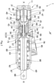
- Figures 1 and 2 show a parking lock 1 according to the invention with an electromagnetic actuator 10 and a piston 70 arranged in a piston housing 60, which is movably arranged in the piston housing 60 along a longitudinal axis XX.
- the piston 70 of the parking lock 1 can be displaced along a longitudinal axis XX between a first position A and a second position B in order to mechanically lock a transmission (not shown), in particular an automatic transmission of a motor vehicle.
- a transmission not shown
- the piston 70 is arranged in the first position A
- the piston 70 is arranged in the second position B.
- the first position A of the piston 70 may correspond to the gear-locking position of the piston 70 and the second position B may correspond to a position of the piston 70 that releases the transmission or vice versa.
- the electromagnetic actuator 10 is arranged on the longitudinal axis X-X and has a first side 11 and a second side 12, wherein the second side 12 faces the piston 70 and the piston housing 60 and the first side 11 forms the free end of the electromagnetic actuator 10.
- the electromagnetic actuator 10 comprises an energizable coil 25 arranged on a coil carrier 26, an armature 20, an actuator plunger 22, a return spring 24, a pole cover 30 and an actuator housing 40.
- the electromagnetic actuator 10 is designed in the manner of a single stroke magnet, which, by means of an electromagnetic force effect of the energized coil 25, causes a linear movement of the armature 20 and of an actuator plunger 22 connected to the armature 20 in the longitudinal axis XX from a stroke start position - which is in the Figures 1 and 2 shown - into the stroke end position (not shown).
- the return is carried out by the spring force of the return spring 24.
- the actuator housing 40 of the electromagnetic actuator 10 comprises a first housing part 41 and a second housing part 42, wherein the first housing part 41 closes the first side 11, i.e. the free end of the electromagnetic actuator 10 and the second housing part 42 is arranged on the side of the electromagnetic actuator 10 facing the piston housing 60.
- the first housing part 41 and the second housing part 42 are each made in one piece from a magnetic and metallic material and serve to guide the magnetic flux resulting from energization of the coil 25.
- the second housing part 42 further comprises a flange 44, a shoulder 45 forming a cylinder surface and a tappet sleeve 43 protruding from the second side 12.
- the actuator plunger 22 is connected to the armature 20 and is mounted on the one hand on the first side 11 of the electromagnetic actuator 10 in a through hole 31 in the pole cover 30 and on the other hand in the second housing part 42 or the plunger sleeve 43 formed on the second housing part 42.
- the armature 20 When the coil 25 is energized, the armature 20 is moved together with the actuator plunger 22 from the stroke start position along the longitudinal axis X-X against the force of the return spring 24.
- the return spring 24 is supported at one end in the actuator housing 40 or in the plunger sleeve 43 of the second housing part 42 and at the other end on a free end arranged on the second side 12, which is provided with a flange.
- the armature 20 is held in the second housing part 42 for a flux transition both in the stroke start position and in the stroke end position, wherein in the stroke start position the pole cover 30 and the armature 20 are spaced apart.
- the stroke end position the air gap between the armature 20 and the pole cover 30 is closed, wherein on the side of the pole cover 30 facing the armature 20 a sleeve-shaped section 32 is formed which is designed to encompass the armature 20 in the stroke end position.
- the sleeve-shaped section 32 can be designed as a control cone 34.
- the free end of the sleeve-shaped section 32 can be arranged approximately in a plane perpendicular to the longitudinal axis X-X with the end of the armature 20 facing the pole cover 30. Furthermore, the free end of the sleeve-shaped section 32 is arranged at a distance from the second housing part 42.
- the electromagnetic actuator 10 is designed to actuate a locking device 50.
- the locking device 50 is arranged on the second side 12 of the electromagnetic actuator 10 facing the piston 70 and comprises an actuating element 52 which is designed to deliver at least one locking member 58 for fixing or locking the piston in the first position A or the second position B - as will be explained in more detail below.
- the piston housing 60 is made of a plastic and has a through-opening 63 which is coaxial with the longitudinal axis X-X and extends between a first side 61, which faces the electromagnetic actuator 10, and a second side 62.
- the piston 70 is arranged in the through-opening 63 so as to be movable in the longitudinal axis X-X.
- the piston housing 60 is firmly connected to the actuator housing 40 in a connection point 5, wherein the piston housing 60 in the preferred embodiment shown is placed over the cylinder surface of the shoulder 45 onto the first housing part 41 until the first side 61 of the piston housing 60 rests against the end face of the flange 44. To compensate for tolerances, a gap 47 can be formed between the end face of the flange 44 and the first side 61 of the piston housing 60.
- a metal-plastic connection is then produced between the actuator housing 40 and the piston housing 60, wherein the metal-plastic connection is particularly preferably produced by an ultrasonic welding process.
- the piston housing 60 can be molded directly onto the actuator housing 40 in a primary molding process, in particular injection molding.
- both the front side of the flange 44 and the cylinder surface of the shoulder 45 can be provided with a surface enlargement, for example a corrugation or at least one undercut 46, whereby in particular high axial forces along the longitudinal axis X-X can be transmitted via the metal-plastic connection.
- the piston 70 is formed in one piece from essentially two tubular sections and can be made from a plastic, preferably in an injection molding process.
- the first tubular section 71 and the second tubular section 72 are connected to one another in a transition region 73.
- the first section 71 together with the transition region 73 and the piston housing 60, encloses a pressure chamber 65 which can be sealed in a liquid-tight and air-tight manner using seals. Furthermore, the first section 71 engages in a hollow cylindrical cavity enclosed between the tappet sleeve 43 and the piston housing 60, so that the first section 71 is guided linearly on the tappet sleeve 43 on the one hand and on the piston housing 60 on the other.
- the piston housing 60 can have at least one control opening 66 through which a medium can be introduced into the pressure chamber 65 in order to displace the piston 70 against the spring force of a compression spring 80 from the first position A to the second position B along the longitudinal axis X-X.
- the piston 70 is guided in the first tubular section 71 on the tappet sleeve 43, wherein the first tubular section 71 has a sliding bushing 75 through which the piston 70 is linearly slidably mounted on the tappet sleeve 43.
- the sliding bushing 75 can be made from a metallic material and particularly preferably the piston 70 is sprayed onto the sliding bushing 75, whereby the latter is held in a form-fitting manner on the inner surface of the first tubular section 71 of the piston 70.
- the sliding bushing 75 can extend completely or only partially over the first tubular section 71 of the piston 70.
- the sliding bush 75 comprises a first recess 76 and a second recess 77, which are spaced apart from one another in the longitudinal axis X-X and form a locking slot 74.
- the distance between the first recess 76 and the second recess 77 corresponds to the stroke of the piston 70 between the first position A and the second position B.
- a spring shoe 78 is formed within the second tubular section 72.
- a parking lock tappet 85 is supported on the spring shoe 78, with the compression spring 80 holding the parking lock tappet 85 pressed against the spring shoe 78 in the longitudinal axis XX.
- the second side 62 of the piston housing 60 is closed by a cover 67, which has a through-opening 68 through which the parking lock tappet 85 can be guided to the transmission.
- the compression spring 80 can be kept pre-tensioned by means of a spring plate 69 between the parking lock tappet or the spring shoe 78 and the spring plate 69 or the cover 67, so that when pressure is applied to the pressure chamber 65, the piston 70 is displaced in the longitudinal axis X-X against the spring force of the compression spring 80 from the first position A to the second position B.
- the locking device 50 fixes the piston in the first position A or the second position B, wherein the electromagnetic actuator 10 can open or close the locking device 50 by means of the actuating element 52 on the actuator plunger 22.
- the at least one locking member 58 is designed as a locking ball and is held in a recess 54 of the tappet sleeve or the second housing part 42.
- the at least one locking member 58 can engage in the first recess 76 or in the second recess 77 of the locking gate 74 depending on the first position A or the second position B of the piston 70 and thereby determine the relative position of the piston 70 to the actuator housing 40.
- the actuating element 52 can be fixedly arranged on the actuator tappet 22 and comprises a first cylinder surface 56, an expansion cone 55 and a second cylinder surface 57.
- the expansion cone 55 connects the first cylinder surface 56 to the second cylinder surface 57.
- the diameter of the first cylinder surface 56 and the second cylinder surface 57 are dimensioned to be different sizes. If the first If the first cylinder surface 56 is operatively connected to the locking members 58, the locking members 58 engage in the respective recess 76, 77. If, on the other hand, the second cylinder surface 56 is operatively connected to the locking members 58, the locking members can leave the respective recess 76, 77 and release a movement of the piston 70 in the longitudinal axis XX.
- the actuating element 52 can be placed as an actuating sleeve 53 on the actuator plunger 22 and held against the flange on the second side of the actuator plunger 22 by means of the return spring 24.
- the present parking lock 1 should be able to be manufactured in an efficient and simple manufacturing process with optimized weight.
- the manufacturing process according to the invention initially provides for the electromagnetic actuator 10 to be provided. To do this, the elements arranged on the first side 11 of the electromagnetic actuator 10 are first mounted, namely the first housing part 41, the coil carrier 26 with the coil 25 and the pole cover 30 held in the first housing part 41. This unit can then be inserted into a holding device so that the entire further assembly of the parking lock 1 can take place from the second side 12 of the electromagnetic actuator 10.
- a second unit is first assembled, which consists of the second housing part 42, the armature 20, the actuator tappet 22, the return spring 24 and the actuating element 52, wherein it is essential to the invention that, in order to enable this type of assembly, the actuator tappet 22 has a diameter that continuously tapers from the second side 12 to the first side 11.
- the actuator tappet 22 can therefore be mounted from the second side 12 together with the second housing part 42 onto the first unit. wherein the actuator plunger 22 penetrates the pole cover 30 and can be held securely against loss on the first side 11 by a securing device.
- the piston housing 60 can then be attached to the actuator housing 40 by means of the metal-plastic connection, whereby the piston housing 60 is either previously formed in a manufacturing process and then connected to the actuator housing 40 or the second housing part 42 or its flange 44 by means of the ultrasonic welding process.
- the piston housing 60 can be molded onto the actuator housing 40, in particular sprayed onto the actuator housing 40 by means of an injection molding process.
- the piston 70, together with the parking lock tappet and the compression spring 80, are then inserted into the through-opening 63 of the piston housing 60 from the second side 62 and the through-opening 63 on the second side 62 of the piston housing is closed by means of the cover 67.
- the cover 67 can be connected to the piston housing 60 by means of a screw connection.
- material-bonded connections are particularly preferred, which avoid unnecessary duplication of material and can be manufactured in a lightweight manner.
Landscapes
- Engineering & Computer Science (AREA)
- General Engineering & Computer Science (AREA)
- Mechanical Engineering (AREA)
- Transportation (AREA)
- Gear-Shifting Mechanisms (AREA)
- Braking Arrangements (AREA)
Description
- Die vorliegende Erfindung betrifft eine Parksperre zum Feststellen eines Getriebes, insbesondere zum Feststellen eines automatischen Getriebes eines Kraftfahrzeugs mit den Merkmalen des Patentanspruchs 1.
- Parksperren sind aus dem Stand der Technik in unterschiedlichen Ausgestaltungen vorbekannt und dienen üblicherweise der Betätigung einer mechanisch wirkenden Sperreinrichtung, durch die das Getriebe eines Kraftfahrzeuges, insbesondere das automatische Getriebe eines Kraftfahrzeuges blockiert werden kann. Hierzu kann die Parksperre in eine das Getriebe freigebende erste Position und eine das Getriebe sperrende zweite Position zugestellt werden, in der beispielsweise eine Sperrklinke oder ein Bolzen in ein Sperrrad des automatischen Getriebes greift und somit das automatische Getriebe in einer Parkposition mechanisch blockiert.
- Zur Betätigung der Parksperre werden in dem Stand der Technik unterschiedliche elektro-hydraulische Parksperren vorgeschlagen, welche sich dadurch auszeichnen, dass die Parksperre einerseits, beispielsweise mittels eines Federspeichers, vorgespannt ist und die Parksperre mittels eines hydraulisch betätigten Zylinders entsperrt werden kann, wobei eine Verriegelungseinrichtung vorgesehen ist, durch welche ein ungewolltes Betätigen der Parksperre verhindert ist.
- Weiteren Stand der Technik bilden die
WO 02 10619 A1 DE 43 32 948 A1 . dieDE 10 2005 013 661 A1 sowie dieUS 2016/061 325 A1 . - Als nachteilig an dem Stand der Technik hat sich herausgestellt, dass die aus dem Stand der Technik bekannten Parksperren eine aufwändige Konstruktion aufweisen, und zur Betätigung einerseits einen hohen hydraulischen Druck und andererseits einen hohen Strom benötigen. Dadurch weisen die aus dem Stand der Technik bekannten Parksperren neben einem erheblichen Gewicht auch eine nicht zu vernachlässigende Baugröße auf, welche im Getriebe vorgesehen werden muss und sind darüber hinaus sowohl in der Herstellung als auch im Betrieb unwirtschaftlich.
- Hier setzt die vorliegende Erfindung an.
- Es ist daher die Aufgabe der vorliegenden Erfindung, eine verbesserte Parksperre mit einer geringeren Baugröße und einem niedrigeren Gewicht vorzuschlagen, welche besonders energieeffizient und zuverlässig das Sperren eines Getriebes, insbesondere eines automatischen Getriebes eines Kraftfahrzeugs ermöglicht und das Einsparen von Kosten in dem Herstellungsprozess bei gleichzeitig einfachen und reproduzierbaren Prozessen ermöglicht. Insbesondere soll der Herstellungsprozess durch ein neuartiges Herstellungsverfahren Kosteneinsparungen ermöglichen.
- Diese Aufgaben wird durch eine Parksperre mit den Merkmalen des Patentanspruchs 1 gelöst.
- Weitere vorteilhafte Ausgestaltungen der Erfindung werden in den Unteransprüchen angegeben.
- Nach Maßgabe der Erfindung ist es vorteilhaft, wenn das Aktorgehäuse eine Stößelhülse umfasst, und das Kolbengehäuse mindestens die Stößelhülse des Gehäuses umgreift und wenn das Aktorgehäuse an der Verbindungsstelle mit dem Kolbengehäuse mit einer Ultraschallschweißverbindung verbunden ist. Hierzu weist besonders bevorzugt das Aktorgehäuse einen Flansch mit einem im wesentlichen zylinderförmigen Absatz auf, wobei der Absatz an den Innendurchmesser des hohlzylindrisch ausgebildeten Kolbengehäuses angepasst ist, und das Kolbengehäuse über den Absatz gegen den Flansch aufgesetzt bzw. aufgeschoben werden kann und in dieser Position mit dem Aktorgehäuse durch Ultraschallverschweißen verbunden wird. Insbesondere ist weiterhin besonders bevorzugt, wenn der Absatz eine Oberflächenvergrößerung aufweist, die in einer bevorzugten Weiterbildung der Erfindung als eine Riffelung, Kreuzriffelung, mindestens eine Hinterschneidung oder dergleichen ausgebildet sein kann, durch die die Festigkeit der Metall-Kunststoff-Verbindung zwischen dem Aktorgehäuse und dem Kolbengehäuse vergrößert werden kann.
- Das Kolbengehäuse wird bevorzugt auf das Aktorgehäuse in einem Urformverfahren, insbesondere durch Spritzgießen aufgeformt. Besonders bevorzugt umfasst das Aktorgehäuse einen Flansch und weiterhin bevorzugt einen an den Flansch angearbeiteten oder angeformten im Wesentlichen zylinderförmigen Absatz. Der Absatz ist an den im Wesentlichen konstanten Innendurchmesser des als hohlzylindrisch auszubildenden Kolbengehäuses angepasst, und das Kolbengehäuse kann auf den Absatz in einem Urformprozess z.B. mittels Spritzgießen aufgeformt bzw. aufgespritzt werden. Insbesondere ist weiterhin besonders bevorzugt, wenn der Absatz eine Oberflächenvergrößerung aufweist, zum Beispiel eine Riffelung, Kreuzriffelung, mindestens eine Hinterschneidung oder dergleichen, durch die die Metall-Kunststoff-Verbindung zwischen dem Aktorgehäuse und dem Kolbengehäuse eine besonders hohe Festigkeit erhält.
- Das Aktorgehäuse ist in einer bevorzugten Ausgestaltung der vorliegenden Erfindung aus einem ersten Gehäuseteil und einem zweiten Gehäuseteil hergestellt, wobei das erste Gehäuseteil auf der von dem Kolbengehäuse abgewandten ersten Seite angeordnet ist und das zweite Gehäuseteil auf der dem Kolbengehäuse zugewandten zweiten Seite. Das erste Gehäuseteil und das zweite Gehäuseteil verschließen den elektromagnetischen Aktor und sind jeweils flussführende Bauteile, welche bevorzugt einstückig aus einem metallischen Werkstoff hergestellt sind.
- Eine weitere vorteilhafte Ausgestaltung der vorliegende Erfindung sieht vor, dass der Kolben in der Längsachse mit der Druckfeder in der ersten Position oder in der zweiten Position vorgespannt gehalten ist. Besonders bevorzugt ist der Kolben durch die Druckfeder in einer das Getriebe sperrenden Position vorgespannt, so dass eine Entriegelung des Getriebes nur möglich ist, wenn das Medium mit einem ausreichenden Druck bereitgestellt wird bzw. wenn der Öldruckkreislauf des automatischen Getriebes einen ausreichenden Öldruck liefert. Der Kolben kann durch die Druckfeder in der das Getriebe sperrenden Position gehalten werden, wodurch ein Notöffnen der Parksperre durch ein manuelles Betätigen des Kolbens entgegen der Spannkraft der Druckfeder erfolgen kann. Hierzu kann eine entsprechende Hilfsvorrichtung an dem Kolben vorgesehen sein, die beispielsweise beim Ausfall des Druckkreislaufes bzw. einer Panne des Kraftfahrzeugs eine manuelle Entriegelung der Parksperre ermöglicht.
- Darüber hinaus kann es weiterhin vorteilhaft sein, wenn der Deckel des Kolbengehäuses nach Art einer Muffenverbindung als Nippel auf das Kolbengehäuse gesetzt ist und/oder auf dem Kolbengehäuse mittels einer form- oder stoffschlüssigen Verbindung, insbesondere mittels Ultraschallschweißen, verbunden ist. Bevorzugt ist der Deckel des Kolbengehäuses aus dem gleichen Kunststoff-Werkstoff hergestellt, wie das Kolbengehäuse. Darüber hinaus ist es vorteilhaft, wenn ein Parksperrenstößel vorgesehen ist, der einenends in der Längsachse an dem Federschuh abgestützt ist und anderenends den Deckel des Kolbengehäuses in einer Durchgangsbohrung durchgreift. Besonders bevorzugt ist der Parksperrenstößel unmittelbar mit der Feder gekoppelt, wodurch der Parksperrenstößel mittels der Feder gegen den Federschuh abgestützt ist. In dieser bevorzugten Ausgestaltung der vorliegenden Erfindung ist die Feder in der Längsachse einenends an dem Parksperrenstößel und somit mittelbar an dem Kolben abgestützt und anderenends an dem Deckel des Gehäuses. Ein aus dem Deckel herausragendes freies Ende des Parksperrenstößels kann eine Sperrklinke oder einen Sperrbolzen aufweisen, um das Getriebe, insbesondere das automatische Getriebe eines Kraftfahrzeugs mechanisch zu sperren.
- Auch hat es sich als vorteilhaft erwiesen, wenn die Verriegelungseinrichtung eine Ausnehmung in dem Aktorgehäuse umfasst und wenn in der Ausnehmung mindestens ein Sperrglied angeordnet ist. Das mindestens eine Sperrglied greift bevorzugt zum Feststellen des Kolbens in einer das Getriebe feststellenden ersten Position oder in einer das Getriebe freigegebenen zweiten Position in den Kolben bzw. die Rastkulisse des Kolbens. Besonders bevorzugt ist die Ausnehmung in eine Stößelhülse des Gehäuses eingearbeitet oder eingeformt, wobei das mindestens eine Sperrglied eine Rastkugel oder einen Raststift umfasst. Das mindestens eine Sperrglied ist eingerichtet, mit dem an dem Aktorstößel angeordneten Betätigungselement zusammenzuwirken und in die Rastaussparungen der Rastkulisse des Kolbens nach Art eines Kugelschnellverschlusses zu ragen, um die Position des Kolbens relativ zu dem Aktorgehäuse bzw. dessen Stö-ßelhülse festzulegen.
- Nach Maßgabe einer weiteren vorteilhaften Ausgestaltung der vorliegenden Erfindung kann es vorteilhaft sein, wenn das Betätigungselement einen Spreizkonus umfasst, der eingerichtet ist, das mindestens eine Sperrelement zu betätigen. Der Spreizkonus verbindet zwei auf dem Betätigungselement ausgebildete Zylinderflächen mit unterschiedlichen Durchmessern, wobei ein erster kleiner Durchmesser dem mindestens einen Sperrglied erlaubt aus einer der Rastaussparungen der Rastkulisse zu gelangen und somit eine Bewegung des Kolbens freizugeben und ein zweiter größerer Durchmesser das mindestens eine Sperrglied in der jeweiligen Rastaussparung in der Rastkulisse formschlüssig hält, wodurch eine Bewegung des Kolbens blockiert bzw. festgelegt bzw. verhindert ist. Der Spreizkonus dient der Zustellung der Sperrglieder.
- Besonders vorteilhaft kann es sein, wenn das Betätigungselement eine auf den Aktorstößel aufgesetzte Betätigungshülse umfasst, welche bevorzugt mit dem Spreizkonus ausgebildet ist. Die Betätigungshülse kann aus einem verschleißfesten Werkstoff hergestellt sein. Durch die zweikomponentige Ausgestaltung ist es möglich, den Aktorstößel und das Betätigungselement aus unterschiedlichen Werkstoffen herzustellen, wodurch eine gewichtsoptimierte und anwendungsoptimierte Werkstoffauswahl für die jeweiligen Komponenten möglich ist.
- Eine weitere vorteilhafte Ausgestaltung der vorliegenden Erfindung sieht vor, dass der elektromagnetische Aktor einen Poldeckel umfasst. Der Poldeckel ist in der Längsachse auf der von dem Kolben abgewandten Seite des Aktorgehäuses angeordnet und ragt in der Längsachse in die bestrombare Spule. Auf der dem Anker zugewandten Seite weist der Poldeckel einen hülsenförmigen Abschnitt auf, der als Steuerkonus ausgebildet ist, wodurch die magnetische Charakteristik des elektromagnetischen Aktors verbessert ist. Der hülsenförmige Abschnitt mit dem Steuerkonus ist ausgebildet, den zylinderförmigen Anker zu umgreifen. Dadurch ist es möglich, den elektromagnetischen Aktor effizienter zu gestalten und kleiner zu dimensionieren, wodurch eine kleine Baugröße und weitere Gewichtsvorteile erzielt werden.
- Auch ist es vorteilhaft, wenn der Aktorstößel aus einem nicht-magnetischen Werkstoff hergestellt ist und den Poldeckel in der Längsachse in einer Durchgangsöffnung durchdringt. Der Aktorstößel kann bevorzugt von der von dem Poldeckel abgewandten zweiten Seite des elektromagnetischen Aktors durch das Ankergehäuse eingesetzt werden. Hierzu wird in einem Verfahrensschritt zunächst die Betätigungshülse auf den Aktorstößel aufgesetzt und anschließend eine Rückstellfeder. Die Rückstellfeder spannt die Verriegelungseinrichtung bevorzugt in eine sperrende Position vor, wobei bevorzugt die Rückstellfeder zwischen dem Ankergehäuse und der Betätigungshülse angeordnet ist, und die Betätigungshülse gegen das Aktorgehäuse vorspannt. Anschließend wird der Aktorstößel in die Stößelhülse des Ankergehäuses eingesetzt, der Anker mit dem Aktorstößel verbunden und der Aktorstößel soweit in den Polkern und das Ankergehäuse eingeschoben, bis er diese vollständig durchdringt. Auf der ersten Seite des elektromagnetischen Aktors kann der Aktorstößel mittels einer Sicherungseinrichtung gehalten werden. Durch diesen Aufbau kann die Parksperre ausschließlich von der zweiten Seite des elektromagnetischen Aktors in einer einzigen Spannung an einer Haltevorrichtung montiert werden.
- Es hat sich weiterhin aus besonders vorteilhaft erwiesen, wenn das Kolbengehäuse in einem Spritzgussverfahren aus einem Kunststoff hergestellt ist. Auch können der Kolben und der Deckel des Kolbengehäuses in einem Spritzgussverfahren aus einem Kunststoff hergestellt werden. Das Kolbengehäuse, aber auch der Deckel oder der Kolben können somit kostengünstig in einer großen Stückzahl hergestellt werden, wobei gleichzeitig eine erhebliche Gewichtsreduzierung gegenüber derzeit bekannten Parksperren, die aus metallischen Werkstoffen hergestellt werden, erreicht werden kann.
- Nachfolgend wird anhand der begleitenden Zeichnung ein erfindungsgemäßes Ausführungsbeispiel der Parksperre im Detail erläutert. Es zeigen:
- Figur 2
- eine erfindungsgemäße Parksperre mit einem elektromagnetischen Aktor, dessen Aktorgehäuse mit einem Kolbengehäuse mittels einer Metall-Kunststoff-Verbindung verbunden ist, wobei in dem Kolbengehäuse ein in der Längsachse beweglicher Kolben zum mechanischen Sperren eines Getriebes in einer ersten Position relativ zu dem Aktorgehäuse angeordnet ist, und
- Figur 1
- die erfindungsgemäße Parksperre gemäß
Figur 2 , wobei der Kolben durch eine durch den elektromagnetischen Aktor betätigbare Verriegelungseinrichtung in einer zweiten Position relativ zu dem Aktorgehäuse festgelegt ist. -
Figuren 1 und2 zeigen eine erfindungsgemäße Parksperre 1 mit einem elektromagnetischen Aktor 10 und einem in einem Kolbengehäuse 60 angeordneten Kolben 70, der in dem Kolbengehäuse 60 entlang einer Längsachse X-X beweglich angeordnet ist. - Der Kolben 70 der Parksperre 1 kann entlang einer Längsachse X-X zwischen einer ersten Position A und einer zweiten Position B verschoben werden, um ein nicht dargestelltes Getriebe, insbesondere ein automatisches Getriebe eines Kraftfahrzeugs, mechanisch zu sperren. In
Figur 2 ist der Kolben 70 in der ersten Position A angeordnet, während dessen in der Darstellung gemäßFigur 1 der Kolben 70 in der zweiten Position B angeordnet ist. Die erste Position A des Kolbens 70 kann der das Getriebe sperrenden Stellung des Kolbens 70 entsprechen und die zweite Position B kann einer das Getriebe freigegebenden Position des Kolbens 70 entsprechen oder umgekehrt. - Der elektromagnetische Aktor 10 ist auf der Längsachse X-X angeordnet und weist eine erste Seite 11 und eine zweite Seite 12 auf, wobei die zweite Seite 12 die dem Kolben 70 und dem Kolbengehäuse 60 zugewandte ist und die erste Seite 11 das freie Ende des elektromagnetischen Aktors 10 bildet.
- Der elektromagnetische Aktor 10 umfasst eine auf einem Spulenträger 26 angeordnete bestrombare Spule 25, einen Anker 20, einen Aktorstößel 22, eine Rückstellfeder 24, einen Poldeckel 30 und ein Aktorgehäuse 40.
- Der elektromagnetische Aktor 10 ist nach Art eines Einfachhubmagnets ausgebildet, der durch eine elektromagnetische Kraftwirkung der bestromten Spule 25 eine lineare Bewegung des Ankers 20 und eines mit dem Anker 20 verbundenen Aktorstößels 22 in der Längsachsachse X-X von einer Hubanfangslage - welche in den
Figuren 1 und2 dargestellt ist - in die Hubendlage (nicht dargestellt) ausführt. Die Rückstellung erfolgt durch die Federkraft der Rückstellfeder 24. - Das Aktorgehäuse 40 des elektromagnetischen Aktors 10 umfasst ein erstes Gehäuseteil 41 und ein zweites Gehäuseteil 42, wobei das erste Gehäuseteil 41 die erste Seite 11, also das freie Ende des elektromagnetischen Aktors 10 verschließt und das zweite Gehäuseteil 42 auf der dem Kolbengehäuse 60 zugewandten Seite des elektromagnetischen Aktors 10 angeordnet ist. Das erste Gehäuseteil 41 und das zweite Gehäuseteil 42 sind jeweils einstückig aus einem magnetischen und metallischen Werkstoff hergestellt und dienen der Führung des magnetischen Flusses, der aus einer Bestromung der Spule 25 resultiert.
- Das zweite Gehäuseteil 42 umfasst weiterhin einen Flansch 44, einen eine Zylindermantelfläche formenden Absatz 45 und eine von der zweiten Seite 12 abstehende Stößelhülse 43.
- Der Aktorstößel 22 ist mit dem Anker 20 verbunden und ist einerseits auf der ersten Seite 11 des elektromagnetischen Aktors 10 in einer Durchgangsbohrung 31 in dem Poldeckel 30 gelagert und anderenends in dem zweiten Gehäuseteil 42 bzw. der an das zweite Gehäuseteil 42 angeformten Stößelhülse 43 gelagert.
- Bei einer Bestromung der Spule 25 wird der Anker 20 zusammen mit dem Aktorstößel 22 von der Hubanfangslage entlang der Längsachse X-X gegen die Kraft der Rückstellfeder 24 bewegt. Die Rückstellfeder 24 ist einenends in dem Aktorgehäuse 40 bzw. in der Stößelhülse 43 des zweiten Gehäuseteils 42 abgestützt und anderenends an einem auf der zweiten Seite 12 angeordneten freien Ende, das mit einem Flansch versehen ist.
- Der Anker 20 ist sowohl in der Hubanfangslage als auch in der Hubendlage in dem zweiten Gehäuseteil 42 für einen Flussübergang gehalten, wobei in der Hubanfangslage der Poldeckel 30 und der Anker 20 beabstandet sind. In der Hubendlage wird der Luftspalt zwischen dem Anker 20 und dem Poldeckel 30 geschlossen, wobei auf der dem Anker 20 zugewandten Seite des Poldeckels 30 ein hülsenförmiger Abschnitt 32 ausgebildet ist, der eingerichtet ist, den Anker 20 in der Hubendlage zu umgreifen.
- Es kann vorteilhaft sein, dass der hülsenförmige Abschnitt 32 als Steuerkonus 34 ausgebildet ist. Das freie Ende des hülsenförmigen Abschnitts 32 kann annähernd in einer Ebene senkrecht zu der Längsachse X-X mit dem dem Poldeckel 30 zugewandten Ende des Ankers 20 angeordnet sein. Weiterhin ist das freie Ende des hülsenförmige Abschnitts 32 beabstandet zu dem zweiten Gehäuseteil 42 angeordnet.
- Der elektromagnetische Aktor 10 ist eingerichtet, eine Verriegelungseinrichtung 50 zu betätigen. Die Verriegelungseinrichtung 50 ist auf der dem Kolben 70 zugewandten zweiten Seite 12 des elektromagnetischen Aktors 10 angeordnet und umfasst ein Betätigungselement 52, welches eingerichtet ist, mindestens ein Sperrglied 58 zum Festlegen oder Sperren des Kolbens in der ersten Position A oder der zweiten Position B - wie nachfolgend noch im Detail erläutert wird - zuzustellen.
- Das Kolbengehäuse 60 ist aus einem Kunststoff hergestellt und weist eine koaxial zu der Längsachse X-X ausgebildete Durchgangsöffnung 63 auf, die sich zwischen einer ersten Seite 61, welche dem elektromagnetische Aktor 10 zugewandt ist, und einer zweiten Seite 62 erstreckt. In der Durchgangsöffnung 63 ist der Kolben 70 in der Längsachse X-X beweglich angeordnet.
- Das Kolbengehäuse 60 ist in einer Verbindungsstelle 5 mit dem Aktorgehäuse 40 fest verbunden, wobei das Kolbengehäuse 60 in dem dargestellten bevorzugten Ausführungsbeispiel über die Zylindermantelfläche des Absatzes 45 auf das erste Gehäuseteil 41 aufgesteckt wird, bis die erste Seite 61 des Kolbengehäuses 60 an der Stirnfläche des Flansches 44 anliegt. Zum Toleranzausgleich kann zwischen der Stirnfläche des Flansches 44 und der ersten Seite 61 des Kolbengehäuses 60 ein Spalt 47 ausgebildet sein. Anschließend wird eine Metall-Kunststoff-Verbindung zwischen dem Aktorgehäuse 40 und dem Kolbengehäuse 60 hergestellt, wobei besonders bevorzugt die Metall-Kunststoff-Verbindung durch ein Ultraschweißverfahren erzeugt wird. Alternativ kann das Kolbengehäuse 60 direkt auf das Aktorgehäuse 40 in einem Urformverfahren, insbesondere Spritzgießen, aufgeformt werden.
- Um der Metall-Kunststoff-Verbindung eine besonders gute Festigkeit zu verleihen, kann sowohl die Stirnseite des Flanschs 44 als auch die Zylindermantelfläche des Absatzes 45 mit einer Oberflächenvergrößerung, beispielsweise einer Riffelung oder mindestens einer Hinterschneidung 46 versehen werden, wodurch insbesondere hohe Axialkräfte entlang der Längsachse X-X über die Metall-Kunststoff-Verbindung übertragen werden können.
- Der Kolben 70 ist einstückig aus im Wesentlichen zwei rohrförmigen Abschnitten ausgebildet und kann aus einem Kunststoff, vorzugsweise in einem Spritzgussverfahren hergestellt werden. Der erste rohrförmige Abschnitt 71 und der zweite rohrförmige Abschnitt 72 sind in einem Übergangsbereich 73 miteinander verbunden.
- Der erste Abschnitt 71 schließt zusammen mit dem Übergangsbereich 73 und dem Kolbengehäuse 60 einen Druckraum 65 ein, welcher mittels Dichtungen flüssigkeits- und luftdicht verschlossen werden kann. Weiterhin greift der erste Abschnitt 71 in einen zwischen der Stößelhülse 43 und dem Kolbengehäuse 60 eingeschlossenen hohlzylindrisch Hohlraum, so dass der erste Abschnitt 71 linear geführt auf der Stößelhülse 43 einerseits und andererseits an dem Kolbengehäuse 60 geführt ist.
- Das Kolbengehäuse 60 kann mindestens eine Steueröffnung 66 aufweisen, durch welches ein Medium in den Druckraum 65 eingebracht werden kann, um den Kolben 70 entgegen der Federkraft einer Druckfeder 80 von der ersten Position A in die zweite Position B entlang der Längsachse X-X zu verschieben.
- Der Kolben 70 ist im ersten rohrförmigen Abschnitt 71 auf der Stößelhülse 43 geführt, wobei der erste rohrförmige Abschnitt 71 eine Gleitbuchse 75 aufweist, durch welche der Kolben 70 auf der Stößelhülse 43 linear gleitgelagert ist. Die Gleitbuchse 75 kann aus einem metallischen Werkstoff hergestellt sein und besonders bevorzugt ist der Kolben 70 auf die Gleitbuchse 75 aufgespritzt, wodurch diese formschlüssig auf der inneren Mantelfläche des ersten rohrförmigen Abschnitts 71 des Kolbens 70 gehalten ist. Die Gleitbuchse 75 kann sich ganz oder nur teilweise über den ersten rohrförmigen Abschnitt 71 des Kolbens 70 erstrecken.
- Die Gleitbuchse 75 umfasst eine erste Aussparung 76 und eine zweite Aussparung 77, welche in der Längsachse X-X zueinander beabstandet sind und eine Rastkulisse 74 bilden. Der Abstand zwischen der ersten Aussparung 76 und der zweiten Aussparung 77 entspricht dem Hub des Kolbens 70 zwischen der ersten Position A und der zweiten Position B.
- Auf der von dem ersten rohrförmigen Abschnitt 71 abgewandten Seite des Übergangsbereichs 73 ist innerhalb des zweiten rohrförmigen Abschnitts 72 ein Federschuh 78 ausgebildet. An dem Federschuh 78 ist ein Parksperrenstößel 85 abgestützt, wobei die Druckfeder 80 den Parksperrenstößel 85 gegen den Federschuh 78 in der Längsachse X-X gedrückt hält.
- Die zweite Seite 62 des Kolbengehäuses 60 ist mittels eines Deckels 67 verschlossen, der eine Durchgangsöffnung 68 aufweist, durch die der Parksperrenstößel 85 zum Getriebe geführt werden kann. Die Druckfeder 80 kann mittels eines Federtellers 69 zwischen dem Parksperrenstößel bzw. dem Federschuh 78 und der Federteller 69 bzw. dem Deckel 67 vorgespannt gehalten werden, so dass bei einer Druckbeaufschlagung des Druckraums 65 der Kolben 70 in der Längsachse X-X entgegen der Federkraft der Druckfeder 80 aus der ersten Position A in die zweite Position B verschoben wird.
- Die Verriegelungseinrichtung 50 legt den Kolben in der ersten Position A oder der zweiten Position B fest, wobei der elektromagnetische Aktor 10 die Verriegelungseinrichtung 50 mittels des Betätigungselements 52 an dem Aktorstößel 22 öffnen oder schließen kann.
- Hierzu ist das mindestens eine Sperrglied 58 als Rastkugel ausgebildet und in einer Ausnehmung 54 der Stößelhülse bzw. des zweiten Gehäuseteils 42 gehalten. Das mindestens eine Sperrglied 58 kann in Abhängigkeit von der ersten Position A oder der zweiten Position B des Kolben 70 in die erste Aussparung 76 oder in die zweite Aussparung 77 der Rastkulisse 74 eingreifen und dadurch die relative Position des Kolbens 70 zu dem Aktorgehäuse 40 festlegen.
- Das Betätigungselement 52 kann fest auf dem Aktorstößel 22 angeordnet sein und umfasst eine erste Zylindermantelfläche 56, einen Spreizkonus 55 und eine zweite Zylindermantelfläche 57. Der Spreizkonus 55 verbindet die erste Zylindermantelfläche 56 mit der zweiten Zylindermantelfläche 57. Der Durchmesser der ersten Zylindermantelfläche 56 und der zweiten Zylindermantelfläche 57 sind unterschiedlich groß bemessen. Wenn die erste Zylindermantelfläche 56 in Wirkverbindung mit den Sperrgliedern 58 steht, greifen die Sperrglieder 58 in die jeweilige Aussparung 76, 77. Wenn dagegen die zweite Zylindermantelfläche 56 in Wirkverbindung mit den Sperrgliedern 58 steht, können die Sperrglieder die jeweilige Aussparung 76, 77 verlassen und geben eine Bewegung des Kolbens 70 in der Längsachse X-X frei.
- Das Betätigungselement 52 kann als Betätigungshülse 53 auf den Aktorstößel 22 aufgesetzt sein und mittels der Rückstellfeder 24 gegen den Flansch auf der zweiten Seite des Aktorstößels 22 gehalten werden.
- Die vorliegende Parksperre 1 soll in einem effizienten und einfachen Herstellungsverfahren gewichtsoptimiert hergestellt werden können. Das erfindungsgemäße Herstellungsverfahren sieht zunächst vor, dass der elektromagnetische Aktor 10 bereitgestellt wird. Hierzu werden zunächst die auf der ersten Seite 11 des elektromagnetischen Aktors 10 angeordneten Elemente montiert, nämlich das erste Gehäuseteil 41, der Spulenträger 26 mit der Spule 25 sowie der in dem ersten Gehäuseteil 41 gehaltene Poldeckel 30. Anschließend kann diese Einheit in eine Haltevorrichtung eingesetzt werden, so dass die gesamte weitere Montage der Parksperre 1 von der zweiten Seite 12 des elektromagnetischen Aktors 10 erfolgen kann. Hierzu wird zunächst eine zweite Einheit, welche aus dem zweiten Gehäuseteil 42, dem Anker 20, dem Aktorstößel 22, der Rückstellfeder 24 und dem Betätigungselement 52 besteht, montiert, wobei erfindungswesentlich ist, dass zur Ermöglichung dieser Montageweise der Aktorstößel 22 einen sich von der zweiten Seite 12 zur ersten Seite 11 stetig verjüngenden Durchmesser aufweist. Der Aktorstößel 22 kann folglich von der zweiten Seite 12 aus zusammen mit dem zweiten Gehäuseteil 42 auf die erste Einheit aufgesetzt werden, wobei der Aktorstößel 22 den Poldeckel 30 durchdringt und auf der ersten Seite 11 durch eine Sicherungseinrichtung verlustsicher gehalten werden kann.
- Anschließend kann das Kolbengehäuse 60 an dem Aktorgehäuse 40 mittels der Metall-Kunststoff-Verbindung befestigt werden, wobei entweder das Kolbengehäuse 60 zuvor in einem Herstellungsverfahren urgeformt ist und anschließend mittels des Ultraschallschweißverfahrens mit dem Aktorgehäuse 40 bzw. dem zweiten Gehäuseteil 42 bzw. dessen Flansch 44 verbunden wird. Alternativ kann das Kolbengehäuse 60 auf das Aktorgehäuse 40 aufgeformt werden, insbesondere durch ein Spritzgussverfahren auf das Aktorgehäuse 40 aufgespritzt werden. Anschließend werden der Kolben 70 zusammen mit dem Parksperrenstößel und der Druckfeder 80 in die Durchgangsöffnung 63 des Kolbengehäuses 60 von der zweiten Seite 62 eingesetzt und die Durchgangsöffnung 63 auf der zweiten Seite 62 des Kolbengehäuses mittels des Deckels 67 verschlossen. Der Deckel 67 kann an dem Kolbengehäuse 60 mittels einer Schraubverbindung verbunden werden. Besonders bevorzugt sind jedoch stoffschlüssige Verbindungen, welche unnötige Materialverdopplung vermeiden und leichtbaugerecht herzustellen sind.
-
- 1
- Parksperre
- 5
- Verbindungsstelle
- 10
- Aktor
- 11
- erste Seite
- 12
- zweite Seite
- 20
- Anker
- 22
- Aktorstößel
- 24
- Rückstellfeder
- 25
- Spule
- 26
- Spulenträger
- 30
- Poldeckel
- 31
- Durchgangsbohrung
- 32
- hülsenförmiger Abschnitt
- 34
- Steuerkonus
- 40
- Aktorgehäuse
- 41
- erstes Gehäuseteil
- 42
- zweites Gehäuseteil
- 43
- Stößelhülse
- 44
- Flansch
- 45
- Absatz
- 46
- Hinterschneidung
- 47
- Spalt
- 50
- Verriegelungseinrichtung
- 52
- Betätigungselement
- 53
- Betätigungshülse
- 54
- Ausnehmung
- 55
- Spreizkonus
- 56
- erste Zylindermantelfläche
- 57
- zweite Zylindermantelfläche
- 58
- Sperrglied
- 60
- Kolbengehäuse
- 61
- erste Seite
- 62
- zweite Seite
- 63
- Durchgangsöffnung
- 65
- Druckraum
- 66
- Steueröffnung
- 67
- Deckel
- 68
- Durchgangsöffnung
- 69
- Federteller
- 70
- Kolben
- 71
- erster Abschnitt
- 72
- zweiter Abschnitt
- 73
- Übergangsbereich
- 74
- Rastkulisse
- 75
- Gleitbuchse
- 76
- erste Aussparung
- 77
- zweite Aussparung
- 78
- Federschuh
- 80
- Druckfeder
- 85
- Parksperrenstößel
- A
- erste Position
- B
- zweite Position
- X-X
- Längsachse
Claims (12)
- Parksperre (1) zum Feststellen eines Getriebes, insbesondere eines Getriebes eines Kraftfahrzeugs, umfassend:- einen Kolben (70) zum mechanischen Sperren des Getriebes,- ein elektromagnetischer Aktor (10) zum Feststellen des Kolbens (70) in einer das Getriebe freigebenden ersten Position (A), mit einer in einem magnetischen Aktorgehäuse (40) angeordneten bestrombaren Spule (25), einem bei der Bestromung der Spule (25) beweglichen Anker (20) mit einem Aktorstößel (22), der in dem Aktorgehäuse (40) gelagert ist und ein Betätigungselement (52) zum Betätigen einer Verriegelungseinrichtung (50) aufweist, durch welches die erste Position (A) des Kolbens (70) relativ zu dem Aktorgehäuse (40) festgelegt ist,- ein Kolbengehäuse (60) in dem der Kolben (70) entlang einer Längsachse (X-X) beweglich angeordnet ist, mit einer koaxial zu der Längsachse (X-X) ausgebildete Durchgangsöffnung (63) auf, die sich zwischen einer ersten Seite (61), welche dem elektromagnetische Aktor (10) zugewandt ist, und einer zweiten Seite (62) erstreckt,- wobei der Kolben (70) mit dem Kolbengehäuse (60) einen Druckraum (65) umschließt,- wobei das Kolbengehäuse (60) mindestens eine Steueröffnung (66) aufweist, durch welches ein Medium in den Druckraum (65) eingebracht werden kann,- wobei das Kolbengehäuse (60) auf der dem Aktorgehäuse (40) abgewandten zweiten Seite (62) durch einen Deckel (67) verschlossen ist, dass der Kolben (70) auf der dem Deckel (67) zugewandten Seite einen Federschuh (78) aufweist, und- wobei eine Druckfeder (80) in dem Kolbengehäuse (40) in der Längsachse (X-X) einenends an dem Federschuh (78) abgestützt ist,dadurch gekennzeichnet, dass- die Druckfeder (80) in dem Kolbengehäuse (40) in der Längsachse (X-X) anderenends an dem Deckel (67) des Kolbengehäuses (60) abgestützt ist,- das Kolbengehäuse (60) aus einem Kunststoff hergestellt ist und in einer Verbindungsstelle (5) mit dem Aktorgehäuse (40) durch eine Metall-Kunststoff-Verbindung verbunden ist,- der elektromagnetische Aktor (10) zum Feststellen des Kolbens (70) in einer das Getriebe sperrenden zweiten Position (B) ausgebildet ist,- die zweite Position (B) des Kolbens (70) relativ zu dem Aktorgehäuse (40) durch das Betätigungselement (52) festgelegt ist,- das Einbringen des Medium in den Druckraum (65) geeignet ist, um den Kolben (70) entgegen der Federkraft der Druckfeder (80) von der ersten Position A in die zweite Position B entlang der Längsachse X-X zu verschieben,- der Kolben (70) eine Rastkulisse (74) aufweist, die auf dem Aktorgehäuse (40) geführt gelagert gehalten ist, und- die Rastkulisse (74) aus einer in den Kolben (70) eingesetzten Gleitbuchse (75) ausgebildet ist.
- Parksperre (1) nach Anspruch 1,
dadurch gekennzeichnet, dass
das Aktorgehäuse (40) und das Kolbengehäuse (60) an der Verbindungsstelle (5) mit einer Ultraschallschweißverbindung verbunden ist. - Parksperre (1) nach Anspruch 1,
dadurch gekennzeichnet, dass
das Kolbengehäuse (60) zur Bildung der Metall-Kunststoff-Verbindung in einem Spritzgussverfahren auf das Aktorgehäuse (40) aufgespritzt ist. - Parksperre (1) nach einem der vorgenannten Ansprüche,
dadurch gekennzeichnet, dass
der Kolben (70) in der Längsachse (X-X) mit der Druckfeder (80) in einer das Getriebe freigebenden ersten Position (A) oder einer das Getriebe sperrenden zweiten Position (B) vorgespannt ist. - Parksperre (1) nach einem der vorgenannten Ansprüche,
dadurch gekennzeichnet, dass
ein Parksperrenstößel (85) vorgesehen ist, der in der Längsachse (X-X) an dem Federschuh (78) abgestützt ist und den Deckel (67) des Kolbengehäuses (60) durchgreift. - Parksperre (1) nach einem der vorgenannten Ansprüche,
dadurch gekennzeichnet, dass
die Verriegelungseinrichtung (50) mindestens eine Ausnehmung (54) in dem Aktorgehäuse (40) umfasst, und dass in der Ausnehmung (54) mindestens ein Sperrglied (58) angeordnet ist, das zum Feststellen des Kolbens (70) in einer ersten Position (A) und in einer zweiten Position (B) in den Kolben (70) greift. - Parksperre (1) nach Anspruch 6,
dadurch gekennzeichnet, dass
das mindestens eine Sperrglied (58) eine Rastkugel oder ein Raststift ist. - Parksperre (1) nach Anspruch 6 oder 7,
dadurch gekennzeichnet, dass
das Betätigungselement (52) einen Spreizkonus (55) umfasst, der eingerichtet ist die Sperrglieder (58) zu betätigen. - Parksperre (1) nach einem der vorgenannten Ansprüche,
dadurch gekennzeichnet, dass
das Betätigungselement (52) aus einer auf den Aktorstö-ßel (22) aufgesetzten Betätigungshülse (53) ausgebildet ist. - Parksperre (1) nach einem der vorgenannten Ansprüche,
dadurch gekennzeichnet, dass
der elektromagnetische Aktor (10) einen Poldeckel (30) umfasst, der in der Längsachse (X-X) auf der dem Kolben (70) abgewandten Seite in die bestrombare Spule (25) ragt und auf der dem Anker (20) zugewandten Seite einen hülsenförmigen Abschnitt (32) umfasst, der als Steuerkonus (34) ausgebildet ist. - Parksperre (1) nach einem der vorgenannten Ansprüche,
dadurch gekennzeichnet, dass
der Aktorstößel (22) aus einem nicht-magnetischen Werkstoff hergestellt ist und den Poldeckel (30) in der Längsachse (X-X) durchdringt. - Parksperre (1) nach einem der vorgenannten Ansprüche,
dadurch gekennzeichnet, dass
das Kolbengehäuse (60) in einem Spritzgussverfahren hergestellt ist.
Priority Applications (5)
| Application Number | Priority Date | Filing Date | Title |
|---|---|---|---|
| EP19786334.3A EP3894725B1 (de) | 2018-12-13 | 2019-10-14 | Sperraktor, sowie parksperre mit einem solchen sperraktor |
| CN201980081861.8A CN113167382B (zh) | 2018-12-13 | 2019-10-14 | 锁定致动器和具有这种锁定致动器的驻车锁 |
| PCT/EP2019/077826 WO2020119980A1 (de) | 2018-12-13 | 2019-10-14 | Sperraktor, sowie parksperre mit einem solchen sperraktor |
| US17/312,506 US12253168B2 (en) | 2018-12-13 | 2019-10-14 | Lock actuator, and park lock comprising such a lock actuator |
| BR112021006564-4A BR112021006564B1 (pt) | 2018-12-13 | 2019-10-14 | Atuador de trava e trava de estacionamento comprendendo tal atuador de trava |
Applications Claiming Priority (1)
| Application Number | Priority Date | Filing Date | Title |
|---|---|---|---|
| DE102018132182.1A DE102018132182A1 (de) | 2018-12-13 | 2018-12-13 | Sperraktor, sowie Parksperre mit einem solchen Sperraktor |
Publications (2)
| Publication Number | Publication Date |
|---|---|
| EP3667128A1 EP3667128A1 (de) | 2020-06-17 |
| EP3667128B1 true EP3667128B1 (de) | 2024-11-06 |
Family
ID=65520177
Family Applications (2)
| Application Number | Title | Priority Date | Filing Date |
|---|---|---|---|
| EP19158621.3A Active EP3667128B1 (de) | 2018-12-13 | 2019-02-21 | Parksperre zum feststellen eines getriebes sowie verfahren zur herstellung einer parksperre |
| EP19786334.3A Active EP3894725B1 (de) | 2018-12-13 | 2019-10-14 | Sperraktor, sowie parksperre mit einem solchen sperraktor |
Family Applications After (1)
| Application Number | Title | Priority Date | Filing Date |
|---|---|---|---|
| EP19786334.3A Active EP3894725B1 (de) | 2018-12-13 | 2019-10-14 | Sperraktor, sowie parksperre mit einem solchen sperraktor |
Country Status (6)
| Country | Link |
|---|---|
| US (1) | US12253168B2 (de) |
| EP (2) | EP3667128B1 (de) |
| CN (1) | CN113167382B (de) |
| DE (1) | DE102018132182A1 (de) |
| ES (1) | ES3008658T3 (de) |
| WO (1) | WO2020119980A1 (de) |
Families Citing this family (6)
| Publication number | Priority date | Publication date | Assignee | Title |
|---|---|---|---|---|
| DE102019205596B3 (de) * | 2019-04-17 | 2020-10-01 | Zf Friedrichshafen Ag | Vorrichtung zum Betätigen einer Parksperreneinrichtung eines Automatgetriebes und Verfahren zum Betreiben der Vorrichtung |
| DE102020103335A1 (de) | 2020-02-10 | 2021-08-12 | Kendrion (Villingen) Gmbh | Sperraktor, Parksperre sowie Kraftfahrzeug mit einer Parksperre |
| DE102020121928B4 (de) | 2020-08-21 | 2024-03-28 | Kendrion (Villingen) Gmbh | Parksperre zum Feststellen eines Getriebes, insbesondere eines Kraftfahrzeuggetriebes |
| DE102020124188B4 (de) | 2020-09-16 | 2022-12-08 | Kendrion (Villingen) Gmbh | Parksperre zum Feststellen eines Getriebes, insbesondere eines Kraftfahrzeuggetriebes, sowie Getriebe |
| DE102020125886A1 (de) | 2020-10-02 | 2022-04-07 | Kendrion (Villingen) Gmbh | Parksperre zum Feststellen eines Getriebes, insbesondere eines Kraftfahrzeuggetriebes, sowie Getriebe |
| DE102022111232B4 (de) * | 2022-05-05 | 2025-08-07 | Svm Schultz Verwaltungs-Gmbh & Co. Kg | Verriegelungseinheit mit zweiteiligem Mittelstück |
Citations (2)
| Publication number | Priority date | Publication date | Assignee | Title |
|---|---|---|---|---|
| US20160061325A1 (en) * | 2014-08-29 | 2016-03-03 | CNH Industrial America, LLC | Parking brake system for a work vehicle |
| US20180224022A1 (en) * | 2017-02-03 | 2018-08-09 | Svm Schultz Verwaltungs-Gmbh & Co. Kg | Valve, in particular a slide valve |
Family Cites Families (16)
| Publication number | Priority date | Publication date | Assignee | Title |
|---|---|---|---|---|
| JPS52154976A (en) * | 1976-06-18 | 1977-12-23 | Teijin Seiki Co Ltd | Actuator |
| US4789366A (en) * | 1987-06-24 | 1988-12-06 | Outboard Marine Corporation | Marine propulsion device ball clutch transmission |
| DE4332948A1 (de) * | 1993-09-28 | 1995-03-30 | Bosch Gmbh Robert | Elektromagnetventil, insbesondere Schaltventil für Automatikgetriebe von Kraftfahrzeugen |
| DE10037565A1 (de) * | 2000-08-02 | 2002-04-04 | Zahnradfabrik Friedrichshafen | Parksperre, insbesondere für ein Kraftfahrzeuggetriebe |
| DE102005013661B4 (de) * | 2005-03-24 | 2007-06-28 | Eichenauer Heizelemente Gmbh & Co. Kg | Heizeinsatz |
| DE102006039862B4 (de) * | 2006-08-25 | 2016-05-19 | Zf Friedrichshafen Ag | Parksperreneinrichtung für Kraftfahrzeuggetriebe |
| DE102007000637A1 (de) * | 2006-11-08 | 2008-05-15 | Zf Friedrichshafen Ag | Vorrichtung zum Betätigen einer Rasteinrichtung |
| KR100989042B1 (ko) * | 2010-01-29 | 2010-10-20 | 주식회사 유니크 | 자동변속기용 파킹 솔레노이드 밸브 |
| EP2458226A1 (de) * | 2010-11-29 | 2012-05-30 | Magnetbau Schramme GmbH & Co. KG | Verriegelungs-Vorrichtung |
| DE102012210571A1 (de) | 2012-06-22 | 2013-12-24 | Zf Friedrichshafen Ag | Vorrichtung zum Betätigen eines Verriegelungsmechanismus |
| DE102012021221A1 (de) * | 2012-10-27 | 2014-04-30 | Volkswagen Aktiengesellschaft | Mechanisches System |
| KR101457366B1 (ko) * | 2013-04-22 | 2014-11-03 | 주식회사 유니크 | 액추에이터 및 액추에이터를 포함하는 유압저장장치 |
| DE102013106301A1 (de) * | 2013-06-18 | 2014-12-18 | Getrag Getriebe- Und Zahnradfabrik Hermann Hagenmeyer Gmbh & Cie Kg | Parksperrenanordnung und Kraftfahrzeuggetriebe |
| DE102014103914A1 (de) * | 2014-03-21 | 2015-09-24 | Getrag Getriebe- Und Zahnradfabrik Hermann Hagenmeyer Gmbh & Cie Kg | Parksperrenanordnung für ein Kraftfahrzeuggetriebe |
| CN204041981U (zh) * | 2014-04-30 | 2014-12-24 | 长城汽车股份有限公司 | 车辆变速器和车辆 |
| DE102016014523A1 (de) * | 2016-12-07 | 2018-06-07 | Fte Automotive Gmbh | Elektrischer Parksperrenaktuator zur Betätigung einer Parksperre in einem Kraftfahrzeug |
-
2018
- 2018-12-13 DE DE102018132182.1A patent/DE102018132182A1/de active Pending
-
2019
- 2019-02-21 EP EP19158621.3A patent/EP3667128B1/de active Active
- 2019-02-21 ES ES19158621T patent/ES3008658T3/es active Active
- 2019-10-14 CN CN201980081861.8A patent/CN113167382B/zh active Active
- 2019-10-14 US US17/312,506 patent/US12253168B2/en active Active
- 2019-10-14 EP EP19786334.3A patent/EP3894725B1/de active Active
- 2019-10-14 WO PCT/EP2019/077826 patent/WO2020119980A1/de not_active Ceased
Patent Citations (2)
| Publication number | Priority date | Publication date | Assignee | Title |
|---|---|---|---|---|
| US20160061325A1 (en) * | 2014-08-29 | 2016-03-03 | CNH Industrial America, LLC | Parking brake system for a work vehicle |
| US20180224022A1 (en) * | 2017-02-03 | 2018-08-09 | Svm Schultz Verwaltungs-Gmbh & Co. Kg | Valve, in particular a slide valve |
Also Published As
| Publication number | Publication date |
|---|---|
| US20220128146A1 (en) | 2022-04-28 |
| EP3894725A1 (de) | 2021-10-20 |
| WO2020119980A1 (de) | 2020-06-18 |
| US12253168B2 (en) | 2025-03-18 |
| BR112021006564A2 (pt) | 2021-07-13 |
| DE102018132182A1 (de) | 2020-06-18 |
| CN113167382A (zh) | 2021-07-23 |
| ES3008658T3 (en) | 2025-03-24 |
| CN113167382B (zh) | 2023-12-01 |
| EP3667128A1 (de) | 2020-06-17 |
| EP3894725B1 (de) | 2025-05-21 |
Similar Documents
| Publication | Publication Date | Title |
|---|---|---|
| EP3667128A1 (de) | Parksperre zum feststellen eines getriebes sowie verfahren zur herstellung einer parksperre | |
| EP1144812B1 (de) | Elektromagnetischer aktuator | |
| DE19700979A1 (de) | Magnetventil | |
| WO1989011600A1 (fr) | Ensemble de piston/cylindre en matiere plastique, procede et dispositif pour sa fabrication | |
| DE102018003752B4 (de) | Parksperrenmodul zur Betätigung einer Parksperre in einem Kraftfahrzeug | |
| EP2458226A1 (de) | Verriegelungs-Vorrichtung | |
| EP3244425A1 (de) | Polrohr für elektromagnete und magnetventile, und verfahren sowie vorrichtung zu dessen herstellung | |
| EP3667130B1 (de) | Verriegelungseinheit mit mittelstück | |
| EP4031786A1 (de) | Elektromagnetventil für ein kraftfahrzeug und verfahren zur herstellung einer bewegungseinheit aus einem anker und einer ventileinheit für ein derartiges elektromagnetventil | |
| DE102020124188B4 (de) | Parksperre zum Feststellen eines Getriebes, insbesondere eines Kraftfahrzeuggetriebes, sowie Getriebe | |
| DE102015107039B4 (de) | Elektromagnetventil sowie sicherheitsrelevantes Pneumatiksystem | |
| EP1503114B1 (de) | Kolben-Kolbenstangen-Einheit | |
| EP4563860B1 (de) | Ankersystem, ventilsystem und magnetventil sowie verfahren zur herstellung eines ventilsystems | |
| DE102020115045A1 (de) | Verriegelungseinheit | |
| EP3523166B1 (de) | Magnetventil mit einstellbarer federkraft | |
| EP0688708A1 (de) | Pneumatischer Bremkraftverstärker und Verfahren zu dessen Herstellung | |
| EP4133199B1 (de) | Ventilvorrichtung | |
| WO2009109369A1 (de) | Elektromagnetische stellvorrichtung | |
| DE10193440B3 (de) | Vorrichtung zur Verbindung eines Hebels mit dem Kolben eines Schaltzylinders | |
| EP3667129B1 (de) | Verriegelungseinheit mit rohrstück | |
| DE102016107766A1 (de) | Elektromagnetventil sowie Betriebsverfahren | |
| DE102020103335A1 (de) | Sperraktor, Parksperre sowie Kraftfahrzeug mit einer Parksperre | |
| DE102023110230B3 (de) | Verriegelungseinheit mit Pilotventil | |
| DE102013224863A1 (de) | Magnetaktor für einen Kraftstoffinjektor sowie Kraftstoffinjektor | |
| DE102018006095B4 (de) | Parksperrenmodul zur Betätigung einer Parksperre in einem Kraftfahrzeug |
Legal Events
| Date | Code | Title | Description |
|---|---|---|---|
| PUAI | Public reference made under article 153(3) epc to a published international application that has entered the european phase |
Free format text: ORIGINAL CODE: 0009012 |
|
| STAA | Information on the status of an ep patent application or granted ep patent |
Free format text: STATUS: THE APPLICATION HAS BEEN PUBLISHED |
|
| AK | Designated contracting states |
Kind code of ref document: A1 Designated state(s): AL AT BE BG CH CY CZ DE DK EE ES FI FR GB GR HR HU IE IS IT LI LT LU LV MC MK MT NL NO PL PT RO RS SE SI SK SM TR |
|
| AX | Request for extension of the european patent |
Extension state: BA ME |
|
| STAA | Information on the status of an ep patent application or granted ep patent |
Free format text: STATUS: REQUEST FOR EXAMINATION WAS MADE |
|
| 17P | Request for examination filed |
Effective date: 20201215 |
|
| RBV | Designated contracting states (corrected) |
Designated state(s): AL AT BE BG CH CY CZ DE DK EE ES FI FR GB GR HR HU IE IS IT LI LT LU LV MC MK MT NL NO PL PT RO RS SE SI SK SM TR |
|
| STAA | Information on the status of an ep patent application or granted ep patent |
Free format text: STATUS: EXAMINATION IS IN PROGRESS |
|
| 17Q | First examination report despatched |
Effective date: 20211008 |
|
| P01 | Opt-out of the competence of the unified patent court (upc) registered |
Effective date: 20230322 |
|
| GRAP | Despatch of communication of intention to grant a patent |
Free format text: ORIGINAL CODE: EPIDOSNIGR1 |
|
| STAA | Information on the status of an ep patent application or granted ep patent |
Free format text: STATUS: GRANT OF PATENT IS INTENDED |
|
| INTG | Intention to grant announced |
Effective date: 20240718 |
|
| GRAS | Grant fee paid |
Free format text: ORIGINAL CODE: EPIDOSNIGR3 |
|
| GRAA | (expected) grant |
Free format text: ORIGINAL CODE: 0009210 |
|
| STAA | Information on the status of an ep patent application or granted ep patent |
Free format text: STATUS: THE PATENT HAS BEEN GRANTED |
|
| AK | Designated contracting states |
Kind code of ref document: B1 Designated state(s): AL AT BE BG CH CY CZ DE DK EE ES FI FR GB GR HR HU IE IS IT LI LT LU LV MC MK MT NL NO PL PT RO RS SE SI SK SM TR |
|
| REG | Reference to a national code |
Ref country code: GB Ref legal event code: FG4D Free format text: NOT ENGLISH |
|
| REG | Reference to a national code |
Ref country code: CH Ref legal event code: EP |
|
| REG | Reference to a national code |
Ref country code: DE Ref legal event code: R096 Ref document number: 502019012418 Country of ref document: DE |
|
| REG | Reference to a national code |
Ref country code: IE Ref legal event code: FG4D Free format text: LANGUAGE OF EP DOCUMENT: GERMAN |
|
| REG | Reference to a national code |
Ref country code: DE Ref legal event code: R081 Ref document number: 502019012418 Country of ref document: DE Owner name: SOLERO TECHNOLOGIES VILLINGEN GMBH, DE Free format text: FORMER OWNER: KENDRION (VILLINGEN) GMBH, MARKDORF, DE |
|
| REG | Reference to a national code |
Ref country code: LT Ref legal event code: MG9D |
|
| REG | Reference to a national code |
Ref country code: NL Ref legal event code: MP Effective date: 20241106 |
|
| REG | Reference to a national code |
Ref country code: ES Ref legal event code: FG2A Ref document number: 3008658 Country of ref document: ES Kind code of ref document: T3 Effective date: 20250324 |
|
| PG25 | Lapsed in a contracting state [announced via postgrant information from national office to epo] |
Ref country code: PT Free format text: LAPSE BECAUSE OF FAILURE TO SUBMIT A TRANSLATION OF THE DESCRIPTION OR TO PAY THE FEE WITHIN THE PRESCRIBED TIME-LIMIT Effective date: 20250306 Ref country code: HR Free format text: LAPSE BECAUSE OF FAILURE TO SUBMIT A TRANSLATION OF THE DESCRIPTION OR TO PAY THE FEE WITHIN THE PRESCRIBED TIME-LIMIT Effective date: 20241106 Ref country code: IS Free format text: LAPSE BECAUSE OF FAILURE TO SUBMIT A TRANSLATION OF THE DESCRIPTION OR TO PAY THE FEE WITHIN THE PRESCRIBED TIME-LIMIT Effective date: 20250306 |
|
| PG25 | Lapsed in a contracting state [announced via postgrant information from national office to epo] |
Ref country code: NL Free format text: LAPSE BECAUSE OF FAILURE TO SUBMIT A TRANSLATION OF THE DESCRIPTION OR TO PAY THE FEE WITHIN THE PRESCRIBED TIME-LIMIT Effective date: 20241106 Ref country code: FI Free format text: LAPSE BECAUSE OF FAILURE TO SUBMIT A TRANSLATION OF THE DESCRIPTION OR TO PAY THE FEE WITHIN THE PRESCRIBED TIME-LIMIT Effective date: 20241106 |
|
| PG25 | Lapsed in a contracting state [announced via postgrant information from national office to epo] |
Ref country code: BG Free format text: LAPSE BECAUSE OF FAILURE TO SUBMIT A TRANSLATION OF THE DESCRIPTION OR TO PAY THE FEE WITHIN THE PRESCRIBED TIME-LIMIT Effective date: 20241106 |
|
| RAP2 | Party data changed (patent owner data changed or rights of a patent transferred) |
Owner name: SOLERO TECHNOLOGIES VILLINGEN GMBH |
|
| PGFP | Annual fee paid to national office [announced via postgrant information from national office to epo] |
Ref country code: ES Payment date: 20250318 Year of fee payment: 7 |
|
| PG25 | Lapsed in a contracting state [announced via postgrant information from national office to epo] |
Ref country code: NO Free format text: LAPSE BECAUSE OF FAILURE TO SUBMIT A TRANSLATION OF THE DESCRIPTION OR TO PAY THE FEE WITHIN THE PRESCRIBED TIME-LIMIT Effective date: 20250206 |
|
| PG25 | Lapsed in a contracting state [announced via postgrant information from national office to epo] |
Ref country code: GR Free format text: LAPSE BECAUSE OF FAILURE TO SUBMIT A TRANSLATION OF THE DESCRIPTION OR TO PAY THE FEE WITHIN THE PRESCRIBED TIME-LIMIT Effective date: 20250207 Ref country code: LV Free format text: LAPSE BECAUSE OF FAILURE TO SUBMIT A TRANSLATION OF THE DESCRIPTION OR TO PAY THE FEE WITHIN THE PRESCRIBED TIME-LIMIT Effective date: 20241106 |
|
| PG25 | Lapsed in a contracting state [announced via postgrant information from national office to epo] |
Ref country code: PL Free format text: LAPSE BECAUSE OF FAILURE TO SUBMIT A TRANSLATION OF THE DESCRIPTION OR TO PAY THE FEE WITHIN THE PRESCRIBED TIME-LIMIT Effective date: 20241106 |
|
| PGFP | Annual fee paid to national office [announced via postgrant information from national office to epo] |
Ref country code: FR Payment date: 20250219 Year of fee payment: 7 |
|
| PGFP | Annual fee paid to national office [announced via postgrant information from national office to epo] |
Ref country code: IT Payment date: 20250228 Year of fee payment: 7 |
|
| PG25 | Lapsed in a contracting state [announced via postgrant information from national office to epo] |
Ref country code: RS Free format text: LAPSE BECAUSE OF FAILURE TO SUBMIT A TRANSLATION OF THE DESCRIPTION OR TO PAY THE FEE WITHIN THE PRESCRIBED TIME-LIMIT Effective date: 20250206 |
|
| PG25 | Lapsed in a contracting state [announced via postgrant information from national office to epo] |
Ref country code: SM Free format text: LAPSE BECAUSE OF FAILURE TO SUBMIT A TRANSLATION OF THE DESCRIPTION OR TO PAY THE FEE WITHIN THE PRESCRIBED TIME-LIMIT Effective date: 20241106 |
|
| PG25 | Lapsed in a contracting state [announced via postgrant information from national office to epo] |
Ref country code: DK Free format text: LAPSE BECAUSE OF FAILURE TO SUBMIT A TRANSLATION OF THE DESCRIPTION OR TO PAY THE FEE WITHIN THE PRESCRIBED TIME-LIMIT Effective date: 20241106 |
|
| PG25 | Lapsed in a contracting state [announced via postgrant information from national office to epo] |
Ref country code: EE Free format text: LAPSE BECAUSE OF FAILURE TO SUBMIT A TRANSLATION OF THE DESCRIPTION OR TO PAY THE FEE WITHIN THE PRESCRIBED TIME-LIMIT Effective date: 20241106 |
|
| PG25 | Lapsed in a contracting state [announced via postgrant information from national office to epo] |
Ref country code: RO Free format text: LAPSE BECAUSE OF FAILURE TO SUBMIT A TRANSLATION OF THE DESCRIPTION OR TO PAY THE FEE WITHIN THE PRESCRIBED TIME-LIMIT Effective date: 20241106 |
|
| PG25 | Lapsed in a contracting state [announced via postgrant information from national office to epo] |
Ref country code: SK Free format text: LAPSE BECAUSE OF FAILURE TO SUBMIT A TRANSLATION OF THE DESCRIPTION OR TO PAY THE FEE WITHIN THE PRESCRIBED TIME-LIMIT Effective date: 20241106 |
|
| PGFP | Annual fee paid to national office [announced via postgrant information from national office to epo] |
Ref country code: CZ Payment date: 20250211 Year of fee payment: 7 |
|
| REG | Reference to a national code |
Ref country code: DE Ref legal event code: R097 Ref document number: 502019012418 Country of ref document: DE |
|
| PG25 | Lapsed in a contracting state [announced via postgrant information from national office to epo] |
Ref country code: SE Free format text: LAPSE BECAUSE OF FAILURE TO SUBMIT A TRANSLATION OF THE DESCRIPTION OR TO PAY THE FEE WITHIN THE PRESCRIBED TIME-LIMIT Effective date: 20241106 |
|
| PLBE | No opposition filed within time limit |
Free format text: ORIGINAL CODE: 0009261 |
|
| STAA | Information on the status of an ep patent application or granted ep patent |
Free format text: STATUS: NO OPPOSITION FILED WITHIN TIME LIMIT |
|
| PG25 | Lapsed in a contracting state [announced via postgrant information from national office to epo] |
Ref country code: MC Free format text: LAPSE BECAUSE OF FAILURE TO SUBMIT A TRANSLATION OF THE DESCRIPTION OR TO PAY THE FEE WITHIN THE PRESCRIBED TIME-LIMIT Effective date: 20241106 |
|
| REG | Reference to a national code |
Ref country code: CH Ref legal event code: PL |
|
| 26N | No opposition filed |
Effective date: 20250807 |
|
| PG25 | Lapsed in a contracting state [announced via postgrant information from national office to epo] |
Ref country code: LU Free format text: LAPSE BECAUSE OF NON-PAYMENT OF DUE FEES Effective date: 20250221 |
|
| PG25 | Lapsed in a contracting state [announced via postgrant information from national office to epo] |
Ref country code: CH Free format text: LAPSE BECAUSE OF NON-PAYMENT OF DUE FEES Effective date: 20250228 |
|
| GBPC | Gb: european patent ceased through non-payment of renewal fee |
Effective date: 20250221 |
|
| REG | Reference to a national code |
Ref country code: BE Ref legal event code: MM Effective date: 20250228 |
|
| PG25 | Lapsed in a contracting state [announced via postgrant information from national office to epo] |
Ref country code: GB Free format text: LAPSE BECAUSE OF NON-PAYMENT OF DUE FEES Effective date: 20250221 |
|
| PG25 | Lapsed in a contracting state [announced via postgrant information from national office to epo] |
Ref country code: BE Free format text: LAPSE BECAUSE OF NON-PAYMENT OF DUE FEES Effective date: 20250228 |
|
| PG25 | Lapsed in a contracting state [announced via postgrant information from national office to epo] |
Ref country code: IE Free format text: LAPSE BECAUSE OF NON-PAYMENT OF DUE FEES Effective date: 20250221 |
|
| PGFP | Annual fee paid to national office [announced via postgrant information from national office to epo] |
Ref country code: DE Payment date: 20260323 Year of fee payment: 8 |
|
| PG25 | Lapsed in a contracting state [announced via postgrant information from national office to epo] |
Ref country code: AT Free format text: LAPSE BECAUSE OF NON-PAYMENT OF DUE FEES Effective date: 20250221 |
|
| REG | Reference to a national code |
Ref country code: AT Ref legal event code: MM01 Ref document number: 1739653 Country of ref document: AT Kind code of ref document: T Effective date: 20250221 |