EP3667054B1 - Kraftstoffversorgungssystem für fahrzeuge mit druckminderer mit rückgewinnung von thermischer energie, und verfahren zur einstellung eines kraftstoffversorgungssystems für fahrzeuge mit rückgewinnung von thermischer energie - Google Patents
Kraftstoffversorgungssystem für fahrzeuge mit druckminderer mit rückgewinnung von thermischer energie, und verfahren zur einstellung eines kraftstoffversorgungssystems für fahrzeuge mit rückgewinnung von thermischer energie Download PDFInfo
- Publication number
- EP3667054B1 EP3667054B1 EP19213565.5A EP19213565A EP3667054B1 EP 3667054 B1 EP3667054 B1 EP 3667054B1 EP 19213565 A EP19213565 A EP 19213565A EP 3667054 B1 EP3667054 B1 EP 3667054B1
- Authority
- EP
- European Patent Office
- Prior art keywords
- pressure reducer
- supply system
- fuel supply
- pressure
- temperature
- Prior art date
- Legal status (The legal status is an assumption and is not a legal conclusion. Google has not performed a legal analysis and makes no representation as to the accuracy of the status listed.)
- Active
Links
Images
Classifications
-
- F—MECHANICAL ENGINEERING; LIGHTING; HEATING; WEAPONS; BLASTING
- F02—COMBUSTION ENGINES; HOT-GAS OR COMBUSTION-PRODUCT ENGINE PLANTS
- F02M—SUPPLYING COMBUSTION ENGINES IN GENERAL WITH COMBUSTIBLE MIXTURES OR CONSTITUENTS THEREOF
- F02M21/00—Apparatus for supplying engines with non-liquid fuels, e.g. gaseous fuels stored in liquid form
- F02M21/02—Apparatus for supplying engines with non-liquid fuels, e.g. gaseous fuels stored in liquid form for gaseous fuels
- F02M21/0218—Details on the gaseous fuel supply system, e.g. tanks, valves, pipes, pumps, rails, injectors or mixers
- F02M21/023—Valves; Pressure or flow regulators in the fuel supply or return system
- F02M21/0239—Pressure or flow regulators therefor
-
- F—MECHANICAL ENGINEERING; LIGHTING; HEATING; WEAPONS; BLASTING
- F02—COMBUSTION ENGINES; HOT-GAS OR COMBUSTION-PRODUCT ENGINE PLANTS
- F02B—INTERNAL-COMBUSTION PISTON ENGINES; COMBUSTION ENGINES IN GENERAL
- F02B29/00—Engines characterised by provision for charging or scavenging not provided for in groups F02B25/00, F02B27/00 or F02B33/00 - F02B39/00; Details thereof
- F02B29/04—Cooling of air intake supply
- F02B29/045—Constructional details of the heat exchangers, e.g. pipes, plates, ribs, insulation, materials, or manufacturing and assembly
- F02B29/0468—Water separation or drainage means
-
- F—MECHANICAL ENGINEERING; LIGHTING; HEATING; WEAPONS; BLASTING
- F02—COMBUSTION ENGINES; HOT-GAS OR COMBUSTION-PRODUCT ENGINE PLANTS
- F02D—CONTROLLING COMBUSTION ENGINES
- F02D19/00—Controlling engines characterised by their use of non-liquid fuels, pluralities of fuels, or non-fuel substances added to the combustible mixtures
- F02D19/02—Controlling engines characterised by their use of non-liquid fuels, pluralities of fuels, or non-fuel substances added to the combustible mixtures peculiar to engines working with gaseous fuels
- F02D19/021—Control of components of the fuel supply system
- F02D19/022—Control of components of the fuel supply system to adjust the fuel pressure, temperature or composition
-
- F—MECHANICAL ENGINEERING; LIGHTING; HEATING; WEAPONS; BLASTING
- F02—COMBUSTION ENGINES; HOT-GAS OR COMBUSTION-PRODUCT ENGINE PLANTS
- F02M—SUPPLYING COMBUSTION ENGINES IN GENERAL WITH COMBUSTIBLE MIXTURES OR CONSTITUENTS THEREOF
- F02M21/00—Apparatus for supplying engines with non-liquid fuels, e.g. gaseous fuels stored in liquid form
- F02M21/02—Apparatus for supplying engines with non-liquid fuels, e.g. gaseous fuels stored in liquid form for gaseous fuels
- F02M21/0218—Details on the gaseous fuel supply system, e.g. tanks, valves, pipes, pumps, rails, injectors or mixers
- F02M21/0287—Details on the gaseous fuel supply system, e.g. tanks, valves, pipes, pumps, rails, injectors or mixers characterised by the transition from liquid to gaseous phase ; Injection in liquid phase; Cooling and low temperature storage
-
- F—MECHANICAL ENGINEERING; LIGHTING; HEATING; WEAPONS; BLASTING
- F02—COMBUSTION ENGINES; HOT-GAS OR COMBUSTION-PRODUCT ENGINE PLANTS
- F02M—SUPPLYING COMBUSTION ENGINES IN GENERAL WITH COMBUSTIBLE MIXTURES OR CONSTITUENTS THEREOF
- F02M21/00—Apparatus for supplying engines with non-liquid fuels, e.g. gaseous fuels stored in liquid form
- F02M21/02—Apparatus for supplying engines with non-liquid fuels, e.g. gaseous fuels stored in liquid form for gaseous fuels
- F02M21/06—Apparatus for de-liquefying, e.g. by heating
-
- F—MECHANICAL ENGINEERING; LIGHTING; HEATING; WEAPONS; BLASTING
- F02—COMBUSTION ENGINES; HOT-GAS OR COMBUSTION-PRODUCT ENGINE PLANTS
- F02M—SUPPLYING COMBUSTION ENGINES IN GENERAL WITH COMBUSTIBLE MIXTURES OR CONSTITUENTS THEREOF
- F02M25/00—Engine-pertinent apparatus for adding non-fuel substances or small quantities of secondary fuel to combustion-air, main fuel or fuel-air mixture
- F02M25/022—Adding fuel and water emulsion, water or steam
- F02M25/0221—Details of the water supply system, e.g. pumps or arrangement of valves
- F02M25/0222—Water recovery or storage
-
- F—MECHANICAL ENGINEERING; LIGHTING; HEATING; WEAPONS; BLASTING
- F02—COMBUSTION ENGINES; HOT-GAS OR COMBUSTION-PRODUCT ENGINE PLANTS
- F02M—SUPPLYING COMBUSTION ENGINES IN GENERAL WITH COMBUSTIBLE MIXTURES OR CONSTITUENTS THEREOF
- F02M26/00—Engine-pertinent apparatus for adding exhaust gases to combustion-air, main fuel or fuel-air mixture, e.g. by exhaust gas recirculation [EGR] systems
- F02M26/13—Arrangement or layout of EGR passages, e.g. in relation to specific engine parts or for incorporation of accessories
- F02M26/22—Arrangement or layout of EGR passages, e.g. in relation to specific engine parts or for incorporation of accessories with coolers in the recirculation passage
- F02M26/29—Constructional details of the coolers, e.g. pipes, plates, ribs, insulation or materials
- F02M26/30—Connections of coolers to other devices, e.g. to valves, heaters, compressors or filters; Coolers characterised by their location on the engine
-
- F—MECHANICAL ENGINEERING; LIGHTING; HEATING; WEAPONS; BLASTING
- F02—COMBUSTION ENGINES; HOT-GAS OR COMBUSTION-PRODUCT ENGINE PLANTS
- F02M—SUPPLYING COMBUSTION ENGINES IN GENERAL WITH COMBUSTIBLE MIXTURES OR CONSTITUENTS THEREOF
- F02M26/00—Engine-pertinent apparatus for adding exhaust gases to combustion-air, main fuel or fuel-air mixture, e.g. by exhaust gas recirculation [EGR] systems
- F02M26/65—Constructional details of EGR valves
- F02M26/72—Housings
- F02M26/73—Housings with means for heating or cooling the EGR valve
-
- Y—GENERAL TAGGING OF NEW TECHNOLOGICAL DEVELOPMENTS; GENERAL TAGGING OF CROSS-SECTIONAL TECHNOLOGIES SPANNING OVER SEVERAL SECTIONS OF THE IPC; TECHNICAL SUBJECTS COVERED BY FORMER USPC CROSS-REFERENCE ART COLLECTIONS [XRACs] AND DIGESTS
- Y02—TECHNOLOGIES OR APPLICATIONS FOR MITIGATION OR ADAPTATION AGAINST CLIMATE CHANGE
- Y02T—CLIMATE CHANGE MITIGATION TECHNOLOGIES RELATED TO TRANSPORTATION
- Y02T10/00—Road transport of goods or passengers
- Y02T10/10—Internal combustion engine [ICE] based vehicles
- Y02T10/12—Improving ICE efficiencies
-
- Y—GENERAL TAGGING OF NEW TECHNOLOGICAL DEVELOPMENTS; GENERAL TAGGING OF CROSS-SECTIONAL TECHNOLOGIES SPANNING OVER SEVERAL SECTIONS OF THE IPC; TECHNICAL SUBJECTS COVERED BY FORMER USPC CROSS-REFERENCE ART COLLECTIONS [XRACs] AND DIGESTS
- Y02—TECHNOLOGIES OR APPLICATIONS FOR MITIGATION OR ADAPTATION AGAINST CLIMATE CHANGE
- Y02T—CLIMATE CHANGE MITIGATION TECHNOLOGIES RELATED TO TRANSPORTATION
- Y02T10/00—Road transport of goods or passengers
- Y02T10/10—Internal combustion engine [ICE] based vehicles
- Y02T10/30—Use of alternative fuels, e.g. biofuels
Definitions
- the present invention relates to a fuel supply system for vehicles provided with pressure reducer with recovery of thermal energy, relative vehicle and method of adjustment of a fuel supply system for vehicles with thermal energy recovery.
- every vehicle with an internal combustion engine, powered completely or partly by gas (such as for example LPG, methane CH4, hydrogen H2, etc.) has a tank/cylinder for storing the same fuel at high pressure (1.6MPa for LPG, 20MPA for methane CH4, 70MPa for hydrogen H2, etc.) to increase the mass capacity thereof.
- the thermal power absorbed is estimated to range from 150W to over 3kW.
- the first phenomenon consists in reaching temperatures at which the movable elements (such as springs, membranes, etc.) of the pressure reducer lose their pressure regulation properties (for methane, hydrogen).
- the second phenomenon consists in the fact that the temperature of the body/gas outlet is lower than the dew point of the gas itself which therefore would not be able to remain in the gaseous phase (in the case of LPG) .
- the known solutions simply provide for a thermal exchange between the engine coolant fluid, appropriately withdrawn by a branch of the system, and the pressure reducer which is therefore thermostatted substantially at the same temperature of the engine.
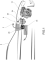
- reference numeral 4 globally indicates an overall schematic view of a fuel supply system for motor applications, such as for example vehicles 8 according to the present invention.
- the present invention may be applied to any type of vehicle 8, such as a motor vehicle, a bus, a truck and the like.
- the present invention applies to supply systems for internal combustion engines or endothermic engines, preferably fed, at least partially, with so-called alternative fuels such as LPG, methane, hydrogen.
- Said fuels which are in the gaseous state in ambient conditions, are normally stored at high pressure inside a tank 16, which is part of the supply system 4.
- the supply system 4 therefore comprises a pressure reducer, fluidly connected in input to said fuel tank 16 containing fuel compressed to an input pressure Pi, and adapted to feed the fuel to the internal combustion engine 12.
- the fuel is fed in the gaseous phase, at a delivery pressure Pm lower than the inlet pressure Pi.
- the fluid at the delivery pressure Pm is then sent to special injectors 22 which inject it directly or indirectly into the combustion chamber 23 of the internal combustion engine 12.
- the pressure reducer 20 reduces the fuel pressure from the input value Pi to a delivery value Pm, so as to correctly supply the internal combustion engine 12.
- the fuel supply system 4 comprises at least one exchanger fluid passing through at least one conveying duct 28 so as to at least partially lap a portion of the body 24 of the pressure reducer 20 to increase the temperature of said body 24 and simultaneously reduce the temperature of said exchanger fluid.
- said conveying duct 28 is provided with at least an adjustment mean 32 suitable to regulate the flow rate of the exchanger fluid that laps the body 24 of the pressure reducer 20, so as to bring the body 24 of the pressure reducer 20 to a temperature higher than a predetermined minimum value.
- said minimum temperature value is equal to the freezing temperature of atmospheric humidity or of that possibly contained in the supply gas under the conditions of use (in the case of use of methane/hydrogen as fuel); the minimum temperature value is above the boiling temperature of the fuel in the gaseous phase at the delivery pressure Pm, in the case of use of LPG as fuel.
- the adjustment mean 32 is operated so as to regulate the flow of exchanging fluid to regulate the temperature of the body 24 of the pressure reducer 20.
- the adjustment mean 32 may comprise a throttle valve.
- thermometer 32 it is also possible to use, as an adjustment mean 32, a thermostatic valve or a proportional valve, both suitable for regulating said flow of exchanger fluid.
- the temperature control of the pressure reducer body 24 preferably takes place by means of a temperature sensor 30, preferably arranged in contact with said body 24.
- the temperature sensor 30 is able to generate a signal which is sent to a control unit 50 of the power supply system 4.
- Said control unit 50 can be specific to the fuel supply system and therefore adapted to interface with a control unit of the internal combustion engine 12, or it can be integrated in the control unit of the internal combustion engine 12.
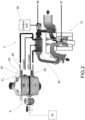
- said at least one conveying duct 28 comprises a ventilation duct of a vehicle air conditioning system: therefore in this solution the exchanger fluid is the flow of air F destined to be introduced into the passenger compartment of the vehicle 8.
- an air/air exchanger 34 is provided in this solution which facilitates the heat exchange between the air of the air conditioning system and the body 24 of the pressure reducer 20.
- said at least one conveying duct 28 further comprises a branch duct of a cooling liquid of the internal combustion engine 12, so as to convey the cooling liquid towards the pressure reducer 20.
- This cooling system will in turn be at least a recirculation pump 21, suitable for moving or recirculating the liquid inside said system in a known manner.
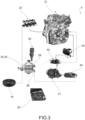
- said at least one conveying duct 28 extends to at least partially lap an exhaust gas recirculation valve 36 (EGR) of the internal combustion engine 12.
- EGR exhaust gas recirculation valve 36
- the at least one conveying duct 28 extends to at least partially lap a heat exchanger 40 fluidly connected with said exhaust gas recirculation valve 36 (EGR).
- EGR exhaust gas recirculation valve 36
- the possible condensate liquid, i.e. water, generated by the heat exchange between the exchanger fluid and the body 24 of the pressure reducer can be collected and conveyed in a water tank (not shown) to be used for water injection phases in the internal combustion engine.
- a water tank not shown
- Other uses are also possible, such as for example the use of water produced in headlamp cleaning systems or also for cleaning the windscreen or rear window.
- the method of adjusting a fuel supply system for vehicles supplied with alternative fuels with a pressure reducer comprises the steps of:
- the adjustment method according to the invention further comprises the steps of connecting the at least one conveying duct 28 to a ventilation duct of an air conditioning system of the vehicle, so as to perform a thermal exchange between the pressure reducer 24 and a fluid of said air conditioning system.
- the adjustment method may comprise the steps of connecting said at least one conveying duct 28 to an exhaust gas recirculation valve 36 so as to perform a thermal exchange between the pressure reducer 24 and the exhaust gas recirculation valve.
- the method may comprise the step of adjusting the temperature of the internal combustion engine 12 by varying the heat exchange between the engine coolant liquid 12 and the pressure reducer 24 and/or the heat exchange between the exhaust gas recirculation valve 36 and the pressure reducer 24.
- the method may also comprise the step of assisting and/or replacing the conditioning system of the passenger compartment by regulating the heat exchange between the pressure regulator 24 and an air flow of the conditioning system.
- the method may also comprise the step of condensing the ambient humidity and producing water in the liquid phase, to be used for water injection techniques in said internal combustion engine.
- the pressure reducer is no longer heated to the temperature of the engine coolant (about 70-90 °C), as in the prior art solutions, but to a lower one, controlled and just enough to guarantee its functionality, generally but not necessarily, a few degrees above zero °C (in the case of methane and hydrogen supply) or above the boiling temperature of the outgoing gas in the case of LPG supply.
- the present invention allows overcoming the drawbacks of the prior art.
- the present invention allows avoiding dispersing the heat (absorption of heat, cooling) which is generated in the pressure reducer of gas-powered vehicles (LPG, CH4, H2, etc.), and use it instead as a free source of "waste" energy for other purposes which today, in the prior art, instead require the use of primary energy.
- a further advantage is given by the fact that, in the case of a fluid connection (i.e. heat exchange) between the pressure reducer and the exhaust gas recirculation valve (EGR), the passage time of the engine from the supply with liquid fuel (typically petrol) to gaseous fuel supply (alternative, such as the LPG), is significantly reduced.
- liquid fuel typically petrol
- gaseous fuel supply alternative, such as the LPG
- EGR is able to heat up significantly before the engine coolant and therefore is able to heat the pressure reducer in much shorter times than conventional solutions (which use the coolant as a heat source).
- the present invention allows optimizing, or reducing, the thermostatting of the internal combustion engine.
- the heating of the pressure reducer device is delegated, as seen, to a branching of the coolant in a passive manner.
- a relatively high amount of heat is dissipated to heat the reducer device, moreover, at a temperature well above that required for the correct operation of the reducer device itself. Therefore, in the known solutions, the heating of the engine is delayed, since a non-negligible quantity of heat is dissipated through the coolant unnecessarily: this results in less than optimal management of the engine temperature.
- the present invention can be easily applied as retrofitting to a pre-existing supply system, without requiring particular distortions and/or adaptations.
- the present invention also allows considerable savings with respect to other known water injection solutions.
Landscapes
- Engineering & Computer Science (AREA)
- Chemical & Material Sciences (AREA)
- Combustion & Propulsion (AREA)
- General Engineering & Computer Science (AREA)
- Mechanical Engineering (AREA)
- General Chemical & Material Sciences (AREA)
- Oil, Petroleum & Natural Gas (AREA)
- Chemical Kinetics & Catalysis (AREA)
- Water Supply & Treatment (AREA)
- Physics & Mathematics (AREA)
- Thermal Sciences (AREA)
- Health & Medical Sciences (AREA)
- Public Health (AREA)
- Exhaust-Gas Circulating Devices (AREA)
Claims (13)
- Kraftstoffversorgungssystem (4) für Motoranwendungen, die mit gasförmigen Kraftstoffen versorgt werden, mit Druckminderer, umfassend:- einen Druckminderer (20), der im Eingang bzw. eingangsseitig mit einem Kraftstofftank (16) verbunden ist, der verdichteten Kraftstoff mit einem Eingangsdruck (Pi) enthält, und geeignet ist, den Kraftstoff am Ausgang bzw. ausgangsseitig in der Gasphase einem Verbrennungsmotor (12) mit einem Lieferdruck (Pm) zuzuführen, der niedriger ist als der Eingangsdruck (Pi),- zumindest ein Tauscherfluid bzw. eine Tauscherflüssigkeit, das bzw. die durch zumindest einen Förderkanal (28) fließt, um einen Abschnitt eines Körpers (24) des Druckminderers (20) zumindest teilweise zu überlappen bzw. zu umgeben, um die Temperatur des Körpers (24) zu erhöhen und gleichzeitig die Temperatur des Tauscherfluids zu verringern,wobei der Förderkanal (28) mit zumindest einem Einstellmittel (32) versehen ist, das geeignet ist, die Flussrate des Tauscherfluids zu regulieren, das den Körper (24) des Druckminderers (20) umgibt, um den Körper (24) des Druckminderers (20) auf eine Temperatur zu bringen, die höher ist als ein vorbestimmter Mindestwert,dadurch gekennzeichnet, dass der zumindest eine Förderkanal (28) einen Belüftungskanal eines Klimaanlagensystems des Fahrzeugs (8) umfasst.
- Kraftstoffversorgungssystem (4) nach Anspruch 1, wobei der vorbestimmte Mindesttemperaturwert höher ist als die Gefriertemperatur der Luftfeuchtigkeit oder derjenigen, die möglicherweise in der Gasversorgung unter den Verwendungsbedingungen enthalten ist, im Fall von Kraftstoffen wie Methan und Wasserstoff.
- Kraftstoffversorgungssystem (4) nach Anspruch 1, wobei der vorbestimmte Mindesttemperaturwert höher ist als eine Siedetemperatur des Kraftstoffs ausgangsseitig in der Gasphase bei dem Lieferdruck (Pm), im Fall von LPG.
- Kraftstoffversorgungssystem (4) nach einem der Ansprüche 1 bis 3, wobei der zumindest eine Förderkanal (28) einen Abzweigkanal eines Kühlfluids bzw. einer Kühlflüssigkeit des Verbrennungsmotors (12) umfasst, um das Kühlfluid zu dem Druckminderer (20) zu befördern.
- Kraftstoffversorgungssystem (4) nach einem der Ansprüche 1 bis 4, wobei sich der zumindest eine Förderkanal (28) so erstreckt, dass er ein Abgasrückführungsventil (36) und den relativen EGR-Kreislauf (12) des Verbrennungsmotors zumindest teilweise überlappt bzw. umgibt.
- Kraftstoffversorgungssystem (4) nach Anspruch 5, wobei sich der zumindest eine Förderkanal (28) so erstreckt, dass er einen Wärmetauscher (34) zumindest teilweise überlappt bzw. umgibt, der mit dem Abgasrückführungsventil (36) fluidisch bzw. flüssigkeitsmäßig verbunden ist.
- Kraftstoffversorgungssystem (4) nach einem der Ansprüche 1 bis 6, wobei ein Abgasrückführungsventil (36) zumindest teilweise in den Körper (24) des Druckminderers (20) integriert ist, um Wärme von dem Abgasrückführungsventil (36) an den Druckminderer (20) abzugeben.
- Kraftstoffversorgungssystem (4) nach einem der Ansprüche 1 bis 7, wobei das Einstellmittel (32) ein Thermostatventil ist.
- Kraftstoffversorgungssystem (4) nach einem der Ansprüche 1 bis 7, wobei das Einstellmittel (32) ein Proportionalventil ist.
- Kraftstoffversorgungssystem (4) nach einem der vorhergehenden Ansprüche, wobei ein Wassertank zum Auffangen von Kondensflüssigkeit vorgesehen ist, die durch den Wärmeaustausch zwischen der Tauscherfluid und dem Körper (24) des Druckminderers (20) erzeugt wird.
- Verfahren zum Einstellen eines Kraftstoffversorgungssystems (4) für Fahrzeuge (8), die mit gasförmigen Kraftstoffen versorgt werden, mit einem Druckminderer, umfassend die Schritte:- Bereitstellen eines Druckminderers (20), der im Eingang bzw. eingangsseitig mit einem Kraftstofftank (16) verbunden ist, der verdichteten Kraftstoff mit einem Eingangsdruck (Pi) enthält, und konfiguriert ist, den Kraftstoff am Ausgang bzw. ausgangsseitig in der Gasphase einem Verbrennungsmotor (12) mit einem Lieferdruck (Pm) zuzuführen, der niedriger ist als der Eingangsdruck (Pi),- Bereitstellen zumindest eines Tauscherfluids bzw. einer Tauscherflüssigkeit, das bzw. die durch zumindest einen Förderkanal (28) fließt, um einen Abschnitt eines Körpers (24) des Druckminderers (20) zumindest teilweise zu überlappten bzw. zu umgeben, um die Temperatur des Körpers (24) zu erhöhen und gleichzeitig die Temperatur des Tauscherfluids zu verringern,- Bereitstellen, an dem Förderkanal (28), zumindest eines Einstellmittels (32),- Einstellen des Einstellmittels (32) dahingehend, die Flussrate des Tauscherfluids zu regulieren, das den Körper (24) des Druckminderers (20) umgibt, um den Körper (24) des Druckminderers (20) auf eine Temperatur zu bringen, die höher ist als ein vorbestimmter Mindestwert,dadurch gekennzeichnet, dass das Verfahren den Schritt des Verbindens des zumindest einen Förderkanals (28) mit einem Lüftungskanal eines Klimaanlagensystems des Fahrzeugs (8) umfasst, um einen Wärmeaustausch zwischen dem Druckminderer (20) und einem Fluid bzw. einer Flüssigkeit des Klimaanlagensystems durchzuführen.
- Verfahren zum Einstellen nach Anspruch 11, umfassend den Schritt:- Verbinden des zumindest einen Förderkanals (28) mit einem Abgasrückführungsventil (36), um einen Wärmeaustausch zwischen dem Druckminderer (20) und dem Abgasrückführungsventil (36) durchzuführen.
- Verfahren zum Einstellen nach einem der Ansprüche 11 bis 12, umfassend den Schritt:- Einstellen der Temperatur des Verbrennungsmotors (12) durch Variieren des Wärmeaustauschs zwischen der Motorkühlflüssigkeit (12) und dem Druckminderer (20) und/oder des Wärmeaustauschs zwischen dem Abgasrückführungs,EGR,-Ventil (32) und dem Druckminderer (20).
Applications Claiming Priority (1)
| Application Number | Priority Date | Filing Date | Title |
|---|---|---|---|
| IT201800010979 | 2018-12-11 |
Publications (2)
| Publication Number | Publication Date |
|---|---|
| EP3667054A1 EP3667054A1 (de) | 2020-06-17 |
| EP3667054B1 true EP3667054B1 (de) | 2024-09-04 |
Family
ID=65861561
Family Applications (1)
| Application Number | Title | Priority Date | Filing Date |
|---|---|---|---|
| EP19213565.5A Active EP3667054B1 (de) | 2018-12-11 | 2019-12-04 | Kraftstoffversorgungssystem für fahrzeuge mit druckminderer mit rückgewinnung von thermischer energie, und verfahren zur einstellung eines kraftstoffversorgungssystems für fahrzeuge mit rückgewinnung von thermischer energie |
Country Status (1)
| Country | Link |
|---|---|
| EP (1) | EP3667054B1 (de) |
Families Citing this family (1)
| Publication number | Priority date | Publication date | Assignee | Title |
|---|---|---|---|---|
| JP7694279B2 (ja) * | 2021-09-14 | 2025-06-18 | スズキ株式会社 | 内燃機関の制御装置 |
Citations (1)
| Publication number | Priority date | Publication date | Assignee | Title |
|---|---|---|---|---|
| DE202018105212U1 (de) * | 2017-09-13 | 2018-11-02 | Fpt Industrial S.P.A. | Mit Flüssiggas betriebenes Fahrzeug |
Family Cites Families (11)
| Publication number | Priority date | Publication date | Assignee | Title |
|---|---|---|---|---|
| US3565201A (en) * | 1969-02-07 | 1971-02-23 | Lng Services | Cryogenic fuel system for land vehicle power plant |
| US5483943A (en) * | 1994-09-19 | 1996-01-16 | Ford Motor Company | Gaseous fuel supply module for automotive internal combustion engine |
| CA2198157C (en) * | 1996-02-21 | 2002-11-05 | Steven A. Carter | Low pressure gas vaporizer and method of operation |
| DE10060788A1 (de) * | 2000-12-07 | 2002-06-27 | Bayerische Motoren Werke Ag | Verfahren und Anordnung zur Bereitstellung eines zündfähigen Arbeitsgases aus einem Kryo-Kraftstoff |
| EP1795729B1 (de) * | 2004-09-17 | 2015-04-15 | Toyota Jidosha Kabushiki Kaisha | Kraftfahrzeug und verfahren zur steuerung eines verbrennungsmotors |
| DE102004057466B4 (de) * | 2004-11-29 | 2009-02-05 | Tescom Europe Gmbh & Co. Kg | Druckregler für ein gasbetriebenes Kraftfahrzeug |
| JP2007332799A (ja) * | 2006-06-12 | 2007-12-27 | Toyota Motor Corp | 内燃機関の排気浄化装置 |
| AU2010366018B2 (en) * | 2010-12-21 | 2015-12-17 | Emer S.P.A. | Vaporizer and pressure reducer device in self - propulsion gas systems |
| DE112011105087T5 (de) * | 2011-03-24 | 2014-07-17 | Toyota Jidosha Kabushiki Kaisha | Abgasrückführungsvorrichtung einer Brennkraftmaschine |
| ES2981747T3 (es) * | 2016-03-04 | 2024-10-10 | Indopar B V | Módulo de acondicionamiento de fluidos gaseosos |
| US10286755B2 (en) * | 2016-09-21 | 2019-05-14 | Ford Global Technologies, Llc | System and methods for extracting water from a HVAC system for water injection |
-
2019
- 2019-12-04 EP EP19213565.5A patent/EP3667054B1/de active Active
Patent Citations (1)
| Publication number | Priority date | Publication date | Assignee | Title |
|---|---|---|---|---|
| DE202018105212U1 (de) * | 2017-09-13 | 2018-11-02 | Fpt Industrial S.P.A. | Mit Flüssiggas betriebenes Fahrzeug |
Also Published As
| Publication number | Publication date |
|---|---|
| EP3667054A1 (de) | 2020-06-17 |
Similar Documents
| Publication | Publication Date | Title |
|---|---|---|
| EP2565436A1 (de) | Ammoniak verbrennender verbrennungsmotor | |
| US8713939B2 (en) | Exhaust heat recovery system | |
| US8950184B2 (en) | Device for utilizing waste heat | |
| EP2969615B1 (de) | Klimaanlage mit wärmekapazität durch ausdehnung einer komprimierten flüssigkeit | |
| US9470115B2 (en) | Split radiator design for heat rejection optimization for a waste heat recovery system | |
| US9109532B2 (en) | Internal combustion engine | |
| US20150135708A1 (en) | Device and method for recovering waste heat energy and a utility vehicle | |
| CN101210526B (zh) | 用于内燃机的燃料系统,尤其是共轨类型的燃 料系统 | |
| KR101792461B1 (ko) | Lng 냉열회수시스템 및 이를 이용한 lng선박의 냉방방법 | |
| EP3667054B1 (de) | Kraftstoffversorgungssystem für fahrzeuge mit druckminderer mit rückgewinnung von thermischer energie, und verfahren zur einstellung eines kraftstoffversorgungssystems für fahrzeuge mit rückgewinnung von thermischer energie | |
| US6145497A (en) | Method and installation for recovering heat in the air supercharging an engine | |
| US20160090873A1 (en) | System for evaporating liquefied natural gas (lng) | |
| CN116255561B (zh) | 一种用于双燃料船舶的lng供气系统 | |
| US6953029B2 (en) | Method of supplying liquid gas to an internal combustion engine, a fuel supply system and a fuel supply aggregate | |
| CN114274843A (zh) | 一种基于液氢汽化冷能利用的车载电池与电控冷却系统 | |
| US20110126796A1 (en) | System For Supplying An Internal Combustion Engine | |
| JP2007177697A (ja) | 液化ガスエンジンの燃料装置 | |
| Feuerecker et al. | Auxiliary heating systems of conventional and heat pump type: technology, performance and efficiency | |
| US12326124B2 (en) | Internal combustion engine with thermochemical recuperation of waste heat and a method for thermochemical recuperation | |
| EP2527244A1 (de) | System und Verfahren zur Bereitstellung von Wärme auf einem Schiff | |
| CA2862664C (en) | Vaporizer system and control strategy | |
| US20210260961A1 (en) | Pressure regulator warm up system for a transport refrigeration unit | |
| KR101983503B1 (ko) | Lng 선박의 난방 시스템 | |
| KR20040093566A (ko) | 압축천연가스 자동차의 연료공급장치와 냉방장치의 상호보완 시스템 | |
| US20250198370A1 (en) | Gaseous fuel supply system for a clean combustion engine of a vehicle |
Legal Events
| Date | Code | Title | Description |
|---|---|---|---|
| PUAI | Public reference made under article 153(3) epc to a published international application that has entered the european phase |
Free format text: ORIGINAL CODE: 0009012 |
|
| STAA | Information on the status of an ep patent application or granted ep patent |
Free format text: STATUS: THE APPLICATION HAS BEEN PUBLISHED |
|
| AK | Designated contracting states |
Kind code of ref document: A1 Designated state(s): AL AT BE BG CH CY CZ DE DK EE ES FI FR GB GR HR HU IE IS IT LI LT LU LV MC MK MT NL NO PL PT RO RS SE SI SK SM TR |
|
| AX | Request for extension of the european patent |
Extension state: BA ME |
|
| STAA | Information on the status of an ep patent application or granted ep patent |
Free format text: STATUS: REQUEST FOR EXAMINATION WAS MADE |
|
| 17P | Request for examination filed |
Effective date: 20201209 |
|
| RBV | Designated contracting states (corrected) |
Designated state(s): AL AT BE BG CH CY CZ DE DK EE ES FI FR GB GR HR HU IE IS IT LI LT LU LV MC MK MT NL NO PL PT RO RS SE SI SK SM TR |
|
| STAA | Information on the status of an ep patent application or granted ep patent |
Free format text: STATUS: EXAMINATION IS IN PROGRESS |
|
| 17Q | First examination report despatched |
Effective date: 20220324 |
|
| RAP3 | Party data changed (applicant data changed or rights of an application transferred) |
Owner name: MARELLI EUROPE S.P.A. |
|
| GRAP | Despatch of communication of intention to grant a patent |
Free format text: ORIGINAL CODE: EPIDOSNIGR1 |
|
| STAA | Information on the status of an ep patent application or granted ep patent |
Free format text: STATUS: GRANT OF PATENT IS INTENDED |
|
| INTG | Intention to grant announced |
Effective date: 20240417 |
|
| GRAS | Grant fee paid |
Free format text: ORIGINAL CODE: EPIDOSNIGR3 |
|
| GRAA | (expected) grant |
Free format text: ORIGINAL CODE: 0009210 |
|
| STAA | Information on the status of an ep patent application or granted ep patent |
Free format text: STATUS: THE PATENT HAS BEEN GRANTED |
|
| AK | Designated contracting states |
Kind code of ref document: B1 Designated state(s): AL AT BE BG CH CY CZ DE DK EE ES FI FR GB GR HR HU IE IS IT LI LT LU LV MC MK MT NL NO PL PT RO RS SE SI SK SM TR |
|
| P01 | Opt-out of the competence of the unified patent court (upc) registered |
Free format text: CASE NUMBER: APP_43585/2024 Effective date: 20240725 |
|
| REG | Reference to a national code |
Ref country code: GB Ref legal event code: FG4D |
|
| REG | Reference to a national code |
Ref country code: CH Ref legal event code: EP |
|
| REG | Reference to a national code |
Ref country code: IE Ref legal event code: FG4D |
|
| REG | Reference to a national code |
Ref country code: DE Ref legal event code: R096 Ref document number: 602019058231 Country of ref document: DE |
|
| REG | Reference to a national code |
Ref country code: LT Ref legal event code: MG9D |
|
| REG | Reference to a national code |
Ref country code: NL Ref legal event code: MP Effective date: 20240904 |
|
| PGFP | Annual fee paid to national office [announced via postgrant information from national office to epo] |
Ref country code: DE Payment date: 20241121 Year of fee payment: 6 |
|
| PG25 | Lapsed in a contracting state [announced via postgrant information from national office to epo] |
Ref country code: NO Free format text: LAPSE BECAUSE OF FAILURE TO SUBMIT A TRANSLATION OF THE DESCRIPTION OR TO PAY THE FEE WITHIN THE PRESCRIBED TIME-LIMIT Effective date: 20241204 |
|
| PG25 | Lapsed in a contracting state [announced via postgrant information from national office to epo] |
Ref country code: GR Free format text: LAPSE BECAUSE OF FAILURE TO SUBMIT A TRANSLATION OF THE DESCRIPTION OR TO PAY THE FEE WITHIN THE PRESCRIBED TIME-LIMIT Effective date: 20241205 Ref country code: PL Free format text: LAPSE BECAUSE OF FAILURE TO SUBMIT A TRANSLATION OF THE DESCRIPTION OR TO PAY THE FEE WITHIN THE PRESCRIBED TIME-LIMIT Effective date: 20240904 Ref country code: FI Free format text: LAPSE BECAUSE OF FAILURE TO SUBMIT A TRANSLATION OF THE DESCRIPTION OR TO PAY THE FEE WITHIN THE PRESCRIBED TIME-LIMIT Effective date: 20240904 |
|
| PG25 | Lapsed in a contracting state [announced via postgrant information from national office to epo] |
Ref country code: BG Free format text: LAPSE BECAUSE OF FAILURE TO SUBMIT A TRANSLATION OF THE DESCRIPTION OR TO PAY THE FEE WITHIN THE PRESCRIBED TIME-LIMIT Effective date: 20240904 |
|
| PGFP | Annual fee paid to national office [announced via postgrant information from national office to epo] |
Ref country code: FR Payment date: 20241121 Year of fee payment: 6 |
|
| PG25 | Lapsed in a contracting state [announced via postgrant information from national office to epo] |
Ref country code: LV Free format text: LAPSE BECAUSE OF FAILURE TO SUBMIT A TRANSLATION OF THE DESCRIPTION OR TO PAY THE FEE WITHIN THE PRESCRIBED TIME-LIMIT Effective date: 20240904 |
|
| PG25 | Lapsed in a contracting state [announced via postgrant information from national office to epo] |
Ref country code: HR Free format text: LAPSE BECAUSE OF FAILURE TO SUBMIT A TRANSLATION OF THE DESCRIPTION OR TO PAY THE FEE WITHIN THE PRESCRIBED TIME-LIMIT Effective date: 20240904 |
|
| PG25 | Lapsed in a contracting state [announced via postgrant information from national office to epo] |
Ref country code: ES Free format text: LAPSE BECAUSE OF FAILURE TO SUBMIT A TRANSLATION OF THE DESCRIPTION OR TO PAY THE FEE WITHIN THE PRESCRIBED TIME-LIMIT Effective date: 20240904 Ref country code: RS Free format text: LAPSE BECAUSE OF FAILURE TO SUBMIT A TRANSLATION OF THE DESCRIPTION OR TO PAY THE FEE WITHIN THE PRESCRIBED TIME-LIMIT Effective date: 20241204 |
|
| PGFP | Annual fee paid to national office [announced via postgrant information from national office to epo] |
Ref country code: IT Payment date: 20241121 Year of fee payment: 6 |
|
| PG25 | Lapsed in a contracting state [announced via postgrant information from national office to epo] |
Ref country code: RS Free format text: LAPSE BECAUSE OF FAILURE TO SUBMIT A TRANSLATION OF THE DESCRIPTION OR TO PAY THE FEE WITHIN THE PRESCRIBED TIME-LIMIT Effective date: 20241204 Ref country code: PL Free format text: LAPSE BECAUSE OF FAILURE TO SUBMIT A TRANSLATION OF THE DESCRIPTION OR TO PAY THE FEE WITHIN THE PRESCRIBED TIME-LIMIT Effective date: 20240904 Ref country code: NO Free format text: LAPSE BECAUSE OF FAILURE TO SUBMIT A TRANSLATION OF THE DESCRIPTION OR TO PAY THE FEE WITHIN THE PRESCRIBED TIME-LIMIT Effective date: 20241204 Ref country code: LV Free format text: LAPSE BECAUSE OF FAILURE TO SUBMIT A TRANSLATION OF THE DESCRIPTION OR TO PAY THE FEE WITHIN THE PRESCRIBED TIME-LIMIT Effective date: 20240904 Ref country code: HR Free format text: LAPSE BECAUSE OF FAILURE TO SUBMIT A TRANSLATION OF THE DESCRIPTION OR TO PAY THE FEE WITHIN THE PRESCRIBED TIME-LIMIT Effective date: 20240904 Ref country code: GR Free format text: LAPSE BECAUSE OF FAILURE TO SUBMIT A TRANSLATION OF THE DESCRIPTION OR TO PAY THE FEE WITHIN THE PRESCRIBED TIME-LIMIT Effective date: 20241205 Ref country code: FI Free format text: LAPSE BECAUSE OF FAILURE TO SUBMIT A TRANSLATION OF THE DESCRIPTION OR TO PAY THE FEE WITHIN THE PRESCRIBED TIME-LIMIT Effective date: 20240904 Ref country code: ES Free format text: LAPSE BECAUSE OF FAILURE TO SUBMIT A TRANSLATION OF THE DESCRIPTION OR TO PAY THE FEE WITHIN THE PRESCRIBED TIME-LIMIT Effective date: 20240904 Ref country code: BG Free format text: LAPSE BECAUSE OF FAILURE TO SUBMIT A TRANSLATION OF THE DESCRIPTION OR TO PAY THE FEE WITHIN THE PRESCRIBED TIME-LIMIT Effective date: 20240904 |
|
| REG | Reference to a national code |
Ref country code: AT Ref legal event code: MK05 Ref document number: 1720634 Country of ref document: AT Kind code of ref document: T Effective date: 20240904 |
|
| PG25 | Lapsed in a contracting state [announced via postgrant information from national office to epo] |
Ref country code: NL Free format text: LAPSE BECAUSE OF FAILURE TO SUBMIT A TRANSLATION OF THE DESCRIPTION OR TO PAY THE FEE WITHIN THE PRESCRIBED TIME-LIMIT Effective date: 20240904 |
|
| PG25 | Lapsed in a contracting state [announced via postgrant information from national office to epo] |
Ref country code: PT Free format text: LAPSE BECAUSE OF FAILURE TO SUBMIT A TRANSLATION OF THE DESCRIPTION OR TO PAY THE FEE WITHIN THE PRESCRIBED TIME-LIMIT Effective date: 20250106 Ref country code: IS Free format text: LAPSE BECAUSE OF FAILURE TO SUBMIT A TRANSLATION OF THE DESCRIPTION OR TO PAY THE FEE WITHIN THE PRESCRIBED TIME-LIMIT Effective date: 20250104 |
|
| PG25 | Lapsed in a contracting state [announced via postgrant information from national office to epo] |
Ref country code: RO Free format text: LAPSE BECAUSE OF FAILURE TO SUBMIT A TRANSLATION OF THE DESCRIPTION OR TO PAY THE FEE WITHIN THE PRESCRIBED TIME-LIMIT Effective date: 20240904 Ref country code: SM Free format text: LAPSE BECAUSE OF FAILURE TO SUBMIT A TRANSLATION OF THE DESCRIPTION OR TO PAY THE FEE WITHIN THE PRESCRIBED TIME-LIMIT Effective date: 20240904 |
|
| PG25 | Lapsed in a contracting state [announced via postgrant information from national office to epo] |
Ref country code: EE Free format text: LAPSE BECAUSE OF FAILURE TO SUBMIT A TRANSLATION OF THE DESCRIPTION OR TO PAY THE FEE WITHIN THE PRESCRIBED TIME-LIMIT Effective date: 20240904 Ref country code: AT Free format text: LAPSE BECAUSE OF FAILURE TO SUBMIT A TRANSLATION OF THE DESCRIPTION OR TO PAY THE FEE WITHIN THE PRESCRIBED TIME-LIMIT Effective date: 20240904 |
|
| PG25 | Lapsed in a contracting state [announced via postgrant information from national office to epo] |
Ref country code: CZ Free format text: LAPSE BECAUSE OF FAILURE TO SUBMIT A TRANSLATION OF THE DESCRIPTION OR TO PAY THE FEE WITHIN THE PRESCRIBED TIME-LIMIT Effective date: 20240904 |
|
| PG25 | Lapsed in a contracting state [announced via postgrant information from national office to epo] |
Ref country code: SK Free format text: LAPSE BECAUSE OF FAILURE TO SUBMIT A TRANSLATION OF THE DESCRIPTION OR TO PAY THE FEE WITHIN THE PRESCRIBED TIME-LIMIT Effective date: 20240904 |
|
| REG | Reference to a national code |
Ref country code: DE Ref legal event code: R097 Ref document number: 602019058231 Country of ref document: DE |
|
| PG25 | Lapsed in a contracting state [announced via postgrant information from national office to epo] |
Ref country code: MC Free format text: LAPSE BECAUSE OF FAILURE TO SUBMIT A TRANSLATION OF THE DESCRIPTION OR TO PAY THE FEE WITHIN THE PRESCRIBED TIME-LIMIT Effective date: 20240904 |
|
| PG25 | Lapsed in a contracting state [announced via postgrant information from national office to epo] |
Ref country code: DK Free format text: LAPSE BECAUSE OF FAILURE TO SUBMIT A TRANSLATION OF THE DESCRIPTION OR TO PAY THE FEE WITHIN THE PRESCRIBED TIME-LIMIT Effective date: 20240904 |
|
| PLBE | No opposition filed within time limit |
Free format text: ORIGINAL CODE: 0009261 |
|
| STAA | Information on the status of an ep patent application or granted ep patent |
Free format text: STATUS: NO OPPOSITION FILED WITHIN TIME LIMIT |
|
| REG | Reference to a national code |
Ref country code: CH Ref legal event code: PL |
|
| 26N | No opposition filed |
Effective date: 20250605 |
|
| PG25 | Lapsed in a contracting state [announced via postgrant information from national office to epo] |
Ref country code: LU Free format text: LAPSE BECAUSE OF NON-PAYMENT OF DUE FEES Effective date: 20241204 |
|
| GBPC | Gb: european patent ceased through non-payment of renewal fee |
Effective date: 20241204 |
|
| PG25 | Lapsed in a contracting state [announced via postgrant information from national office to epo] |
Ref country code: SE Free format text: LAPSE BECAUSE OF FAILURE TO SUBMIT A TRANSLATION OF THE DESCRIPTION OR TO PAY THE FEE WITHIN THE PRESCRIBED TIME-LIMIT Effective date: 20240904 |
|
| REG | Reference to a national code |
Ref country code: BE Ref legal event code: MM Effective date: 20241231 |
|
| PG25 | Lapsed in a contracting state [announced via postgrant information from national office to epo] |
Ref country code: GB Free format text: LAPSE BECAUSE OF NON-PAYMENT OF DUE FEES Effective date: 20241204 Ref country code: BE Free format text: LAPSE BECAUSE OF NON-PAYMENT OF DUE FEES Effective date: 20241231 |
|
| PG25 | Lapsed in a contracting state [announced via postgrant information from national office to epo] |
Ref country code: CH Free format text: LAPSE BECAUSE OF NON-PAYMENT OF DUE FEES Effective date: 20241231 |
|
| PG25 | Lapsed in a contracting state [announced via postgrant information from national office to epo] |
Ref country code: IE Free format text: LAPSE BECAUSE OF NON-PAYMENT OF DUE FEES Effective date: 20241204 |