EP3666602A1 - Air bag device - Google Patents
Air bag device Download PDFInfo
- Publication number
- EP3666602A1 EP3666602A1 EP18862094.2A EP18862094A EP3666602A1 EP 3666602 A1 EP3666602 A1 EP 3666602A1 EP 18862094 A EP18862094 A EP 18862094A EP 3666602 A1 EP3666602 A1 EP 3666602A1
- Authority
- EP
- European Patent Office
- Prior art keywords
- air bag
- seat
- dummy
- vehicle
- reclining
- Prior art date
- Legal status (The legal status is an assumption and is not a legal conclusion. Google has not performed a legal analysis and makes no representation as to the accuracy of the status listed.)
- Withdrawn
Links
- 210000003127 knee Anatomy 0.000 claims description 8
- 101001108245 Cavia porcellus Neuronal pentraxin-2 Proteins 0.000 description 7
- 230000004308 accommodation Effects 0.000 description 6
- 239000004744 fabric Substances 0.000 description 3
- 239000002184 metal Substances 0.000 description 2
- 230000000452 restraining effect Effects 0.000 description 2
- 230000000717 retained effect Effects 0.000 description 2
- 229910000831 Steel Inorganic materials 0.000 description 1
- 230000001771 impaired effect Effects 0.000 description 1
- 210000002414 leg Anatomy 0.000 description 1
- 239000011347 resin Substances 0.000 description 1
- 229920005989 resin Polymers 0.000 description 1
- 239000010959 steel Substances 0.000 description 1
- 239000000725 suspension Substances 0.000 description 1
Images




Classifications
-
- B—PERFORMING OPERATIONS; TRANSPORTING
- B60—VEHICLES IN GENERAL
- B60R—VEHICLES, VEHICLE FITTINGS, OR VEHICLE PARTS, NOT OTHERWISE PROVIDED FOR
- B60R21/00—Arrangements or fittings on vehicles for protecting or preventing injuries to occupants or pedestrians in case of accidents or other traffic risks
- B60R21/02—Occupant safety arrangements or fittings, e.g. crash pads
- B60R21/16—Inflatable occupant restraints or confinements designed to inflate upon impact or impending impact, e.g. air bags
- B60R21/23—Inflatable members
- B60R21/231—Inflatable members characterised by their shape, construction or spatial configuration
-
- B—PERFORMING OPERATIONS; TRANSPORTING
- B60—VEHICLES IN GENERAL
- B60N—SEATS SPECIALLY ADAPTED FOR VEHICLES; VEHICLE PASSENGER ACCOMMODATION NOT OTHERWISE PROVIDED FOR
- B60N2/00—Seats specially adapted for vehicles; Arrangement or mounting of seats in vehicles
- B60N2/02—Seats specially adapted for vehicles; Arrangement or mounting of seats in vehicles the seat or part thereof being movable, e.g. adjustable
- B60N2/22—Seats specially adapted for vehicles; Arrangement or mounting of seats in vehicles the seat or part thereof being movable, e.g. adjustable the back-rest being adjustable
-
- B—PERFORMING OPERATIONS; TRANSPORTING
- B60—VEHICLES IN GENERAL
- B60N—SEATS SPECIALLY ADAPTED FOR VEHICLES; VEHICLE PASSENGER ACCOMMODATION NOT OTHERWISE PROVIDED FOR
- B60N2/00—Seats specially adapted for vehicles; Arrangement or mounting of seats in vehicles
- B60N2/24—Seats specially adapted for vehicles; Arrangement or mounting of seats in vehicles for particular purposes or particular vehicles
- B60N2/42—Seats specially adapted for vehicles; Arrangement or mounting of seats in vehicles for particular purposes or particular vehicles the seat constructed to protect the occupant from the effect of abnormal g-forces, e.g. crash or safety seats
- B60N2/427—Seats or parts thereof displaced during a crash
- B60N2/42727—Seats or parts thereof displaced during a crash involving substantially rigid displacement
- B60N2/42745—Seats or parts thereof displaced during a crash involving substantially rigid displacement of the back-rest
-
- B—PERFORMING OPERATIONS; TRANSPORTING
- B60—VEHICLES IN GENERAL
- B60R—VEHICLES, VEHICLE FITTINGS, OR VEHICLE PARTS, NOT OTHERWISE PROVIDED FOR
- B60R21/00—Arrangements or fittings on vehicles for protecting or preventing injuries to occupants or pedestrians in case of accidents or other traffic risks
- B60R21/02—Occupant safety arrangements or fittings, e.g. crash pads
- B60R21/16—Inflatable occupant restraints or confinements designed to inflate upon impact or impending impact, e.g. air bags
- B60R21/20—Arrangements for storing inflatable members in their non-use or deflated condition; Arrangement or mounting of air bag modules or components
- B60R21/207—Arrangements for storing inflatable members in their non-use or deflated condition; Arrangement or mounting of air bag modules or components in vehicle seats
-
- B—PERFORMING OPERATIONS; TRANSPORTING
- B60—VEHICLES IN GENERAL
- B60R—VEHICLES, VEHICLE FITTINGS, OR VEHICLE PARTS, NOT OTHERWISE PROVIDED FOR
- B60R21/00—Arrangements or fittings on vehicles for protecting or preventing injuries to occupants or pedestrians in case of accidents or other traffic risks
- B60R21/02—Occupant safety arrangements or fittings, e.g. crash pads
- B60R21/16—Inflatable occupant restraints or confinements designed to inflate upon impact or impending impact, e.g. air bags
- B60R21/23—Inflatable members
- B60R21/231—Inflatable members characterised by their shape, construction or spatial configuration
- B60R2021/23153—Inflatable members characterised by their shape, construction or spatial configuration specially adapted for rear seat passengers
-
- B—PERFORMING OPERATIONS; TRANSPORTING
- B60—VEHICLES IN GENERAL
- B60R—VEHICLES, VEHICLE FITTINGS, OR VEHICLE PARTS, NOT OTHERWISE PROVIDED FOR
- B60R21/00—Arrangements or fittings on vehicles for protecting or preventing injuries to occupants or pedestrians in case of accidents or other traffic risks
- B60R21/02—Occupant safety arrangements or fittings, e.g. crash pads
- B60R21/16—Inflatable occupant restraints or confinements designed to inflate upon impact or impending impact, e.g. air bags
- B60R21/23—Inflatable members
- B60R21/231—Inflatable members characterised by their shape, construction or spatial configuration
- B60R2021/23169—Inflatable members characterised by their shape, construction or spatial configuration specially adapted for knee protection
Definitions
- the present invention relates to an air bag device for a vehicle, which includes an air bag that deploys from a back surface of a seat back of a front seat toward a rear seat.
- an air bag device for a rear seat passenger to protect a passenger (a rear seat passenger) seated on the rear seat is provided.
- protection performance of a rear seat passenger may change due to a reclining angle of a seat back of a front seat.
- a distance between the seat back and a rear seat passenger changes according to a reclining angle of the seat back of the front seat, for example, when the reclining angle is large, a deployed position of the air bag may be too close to the rear seat passenger.
- Patent Literature 1 discloses a device.
- the air bag device disclosed in Patent Literature 1 is configured to control adjustment of a deploying area of an air bag. Specifically, when collision of a vehicle is predicted, and an angle of a seat back of a front seat is equal to or larger than a predetermined angle, a reclining motor incorporated in the front seat is driven, and the seat back is raised in such a way that the angle of the seat back is set to an appropriate angle.
- Patent Literature 1 Japanese Unexamined Patent Application Publication No. 2017-30636
- An object of the present invention is to provide an air bag device that enables to appropriately protect a rear seat passenger with a simplified structure, irrespective of a reclining angle of a seat back of a front seat.
- the present invention is directed to an air bag device to be installed in a vehicle including a front seat and a rear seat disposed away from each other in a front-rear direction of the vehicle, and a reclining mechanism provided in the front seat to allow a seat back to pivot about a reclining pivot axis.
- the air bag device includes an air bag that deploys from a back surface of the seat back of the front seat toward the rear seat. At least an upper rear portion of the air bag in a deployed state is formed into an arc shape about the reclining pivot axis in a side view of the vehicle.
- FIG. 1 is a side view illustrating an air bag device according to the present invention (for convenience of illustration, illustrating a deployed state of an air bag).
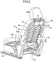
- FIG. 2 is a perspective view illustrating a front seat.
- FIG. 3 is an exploded perspective view illustrating essential parts of the front seat.
- the arrow F indicates a vehicle front side
- the arrow R indicates a vehicle rear side.
- a front seat 10 and a rear seat 30 are disposed side by side in such a way as to be away from each other in a front-rear direction of the vehicle (hereinafter, simply referred to as a front-rear direction).
- the front seat 10 When the front seat 10 is set as a driver's seat or a passenger's seat (a seat of a first row), it is possible to set the rear seat 30, as a seat of a second row immediately behind the front seat 10. Further, when the front seat 10 is set as a seat of a second row, it is possible to set the rear seat 30 as a seat of a third row.
- the front seat 10 is mounted in such a way that a position thereof is adjustable in the front-rear direction with respect to front and rear brackets 12 and 13 provided on an upper portion of a floor panel 11 via a pair of seat sliding rails 14 and 14 constituted of a lower rail (a fixed rail) and an upper rail (a movable rail).
- the front seat 10 includes a seat cushion 10C for forming a seating surface of a passenger, a seat back 10B for forming a back rest surface of the passenger, and a head rest 10H capable of adjusting a height for holding the head of the passenger.
- the front seat 10 includes a reclining mechanism 16 for allowing the seat back 10B to pivot about a reclining pivot axis 15 in such a way that an angle of the seat back 10B is adjustable.
- the seat cushion 10C of the front seat 10 includes a seat cushion frame 17.
- the seat back 10B includes a seat back frame 20.
- the seat back frame 20 includes an upper frame 18 constituted of a metal pipe, located on an upper portion of the seat back frame 20, and formed into a gate shape in a rear view, and lower frames 19 and 19 made of sheet metal and located on both left and right sides of the seat back frame 20.
- a suspension mat 21 constituted of a spring member is disposed between side portions of the seat back frame 20.
- a reaction plate 22 is mounted on an upper portion of the upper frame 18 constituting the seat back frame 20, specifically, as illustrated in FIG. 3 , on a portion having high rigidity and surrounded by an upper side portion 18a and left and right leg portions 18b and 18c of the upper frame 18.
- a box-shaped air bag accommodation case 23 is mounted on a back surface of the reaction plate 22.
- An air bag 24 (see FIG. 1 ) is accommodated in a folded state within an accommodation space of the air bag accommodation case 23.
- a fabric cover 25 is provided on a back surface of the air bag accommodation case 23 in such a way as to cover the folded air bag 24 from behind.
- a pair of left and right gas supply pipes 26 and 26 are provided in such a way as to communicate with an interior of the air bag 24, which is accommodated in a folded state within the air bag accommodation case 23.
- the gas supply pipe 26 extends downwardly along the upper frame 18, and a lower end thereof is located on the inner side of the lower frame 19.
- An inflator 27 as a gas generator is mounted on a lower end of the gas supply pipe 26.
- a pair of left and right inflators 27, 27 are mounted on the lower frames 19 and 19 from the inner sides thereof.
- the air bag device is constituted of the reaction plate 22 made of a steel plate or resin and configured to support a reaction force generated when the air bag 24 deploys, the air bag 24 as a bag member, the air bag accommodation case 23, the fabric cover 25, the gas supply pipe 26 constituted of a fabric tube or the like, and the inflator 27.
- the air bag device is configured in such a way that, when the vehicle collides or is predicted to collide, gas generated in the inflator 27 is supplied into the air bag 24 via the gas supply pipe 26 to thereby deploy the air bag 24 toward a passenger seated on the rear seat 30.
- the rear seat 30 includes a seat cushion 30C for forming a seating surface of a passenger, a seat back 30B for forming a back rest surface of the passenger, and a head rest 30H capable of adjusting a height for holding the head of the passenger.
- the air bag device is configured in such a way that the air bag 24 deploys from the back surface of the seat back 10B of the front seat 10 toward the rear seat 30 to protect a passenger seated on the rear seat 30.
- the air bag device is configured in such a way as to protect a passenger seated on the rear seat 30 by the air bag 24 that deploys from the back surface of the seat back 10B of the front seat 10 located immediately in front of the rear seat 30.
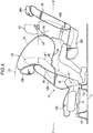
- FIG. 4 is a side view, when the air bag deploys in a state that an AF05 dummy D1 is placed on the rear seat 30.
- FIG. 5 is a plan view of essential parts in FIG. 4 .
- FIG. 6 is a side view, when the air bag deploys in a state that an AM50 dummy D2 is placed on the rear seat 30.
- FIG. 7 is a plan view of essential parts in FIG. 6 .
- FIG. 8 is a side view, when the air bag deploys in a state that an AM95 dummy D3 is placed on the rear seat 30.
- FIG. 9 is a plan view of essential parts in FIG. 8 .
- the AF05 dummy D1 is a human body dummy of a small-sized American female adult ( woman of height from 148.6 to 153.7 cm and weight from 44.1 to 48.6 kg).
- the AM50 dummy D2 is a human body dummy of an average-sized American male adult (man of height from 160.0 to 177.8 cm and weight from 59.5 to 80.5 kg).
- the AM95 dummy D3 is a human body dummy of a large-sized American male adult (man of height from 185.4 to 189.2 cm and weight from 98.6 to 109.1 kg).
- the air bag 24 in a deployed state includes an arc-shaped area 31 (see the area indicated by the arrow in FIG. 1 ) such that an upper rear portion of the air bag 24 is formed into an arc shape that coincides or substantially coincides with an arc C1 about the reclining pivot axis 15 in a side view of the vehicle.
- the deployed shape of the air bag 24 is retained by a plurality of tethers formed in the air bag 24. Vent holes as discharge holes for controlling an inner pressure of the air bag to discharge gas are formed in required positions of the air bag 24. Further, as illustrated in FIGS. 5 , 7 , and 9 , the deployed shape of the air bag 24 in a plan view is formed to be a substantially rectangular shape.
- the air bag device can appropriately protect a passenger seated on the rear seat 30 with a simplified structure, irrespective of a reclining angle of the seat back 10B of the front seat 10.
- the arc-shaped area 31 retains a state such that a shape thereof coincides or substantially coincides with the arc C1. Therefore, it is possible to appropriately protect a passenger (a passenger of a physical constitution equivalent to the AF05 dummy D1) seated on the rear seat 30, irrespective of a reclining angle of the seat back 10B of the front seat 10.
- the arc-shaped area 31 retains a state such that a shape thereof coincides or substantially coincides with the arc C1. Therefore, it is possible to appropriately protect a passenger (a passenger of a physical constitution equivalent to the AM50 dummy D2 or the AM95 dummy D3) seated on the rear seat 30, irrespective of a reclining angle of the seat back 10B of the front seat 10.
- the arc-shaped area 31, of an upper rear portion of the air bag 24 in a deployed state, which is formed into an arc shape is set as an area from a position p1 (a head centroid associated position) associated with a head centroid 32 of the AM95 dummy D3 to a position p2 (a jaw associated position or a lower jaw associated position) associated with the jaw (specifically, the lower jaw) of the AF05 dummy D1, when a reclining angle of the seat back 10B of the front seat 10 is equal to a specific angle (as illustrated by the solid line in FIG. 1 , an angle ⁇ inclined rearwardly with respect to an imaginary vertical straight line VER by 24 to 26°).
- the arc-shaped area 31 is set as an area from a position p0 (a head top vicinity associated position) associated with a vicinity of the head top of the AM95 dummy D3 to the jaw associated position p2 of the AF05 dummy D1, specifically, to the lower jaw associated position, while including the head centroid position associated position p1 of the AM95 dummy D3, when a reclining angle is equal to the specific reclining angle ⁇ of the seat back 10B.
- deploying the air bag 24 enables to protect the AF05 dummy D1 illustrated in FIG. 4 , the AM50 dummy D2 illustrated in FIG. 6 , and the AM95 dummy D3 illustrated in FIG. 8 , in other words, seated passengers of substantially all physical constitutions from small-sized female adults to large-sized male adults.
- the arc-shaped area 31 as an area from the head top vicinity associated position p0 of the AM95 dummy D3 to the jaw associated position p2 of the AF05 dummy D1, as illustrated by the imaginary line ⁇ 3 in FIG. 8 , even when the seat back 10B of the front seat 10 is inclined further rearwardly from the specific angle ⁇ by about 12 degrees, it is possible to securely receive the head centroid 32 of the AM95 dummy D3 by the air bag 24.
- an area 33 (see the area illustrated by the arrow in FIG. 1 ), of the air bag 24 in a deployed state, on a lower side with respect to the jaw associated position p2 of the AF05 dummy D1 is formed into an arc shape in a side view of the vehicle.
- the area 33 is set in such a way that a curvature radius thereof is smaller than a curvature radius of the arc-shaped area 31 (in the embodiment, the curvature radius of the lower area 33 is set to 21 to 23% with respect to the curvature radius of the arc-shaped area 31; however, the numerical value is not limited to the above).
- the area 33 (the lower area 33) on a lower side with respect to the jaw associated position p2 has a larger curvature. Accordingly, a projection amount of the air bag 24 in a direction toward a chest portion of a passenger seated on the rear seat 30, particularly, of a small-sized female adult equivalent to the AF05 dummy D1 becomes small, and the chest portion of the seated passenger is less likely to be pressed by the air bag 24.
- an upwardly indented recess portion 35 in a side view of the vehicle, is formed in a lower surface 34 of the air bag 24 in a deployed state in association with a knee portion of a passenger seated on the rear seat 30.
- the shape of the recess portion 35 is also retained by the tethers formed in the air bag 24.
- a knee portion of a seated passenger is less likely to be pressed, and movement of the knee portion is not impaired.
- the deployed air bag 24 is configured in such a way that the lower surface 34 including the recess portion 35 does not come into contact with a femoral region of the AM95 dummy D3.
- pressing of the femoral region by the air bag 24 is avoided.
- a maximum width W2 of the air bag 24 in a deployed state in the vehicle width direction is set to be equal to or larger than a shoulder width W1 (a so-called torso width) of the AM95 dummy D3 placed on the rear seat 30 in a plan view (in other words, W2>W1).
- the air bag 24 in order to increase a restraining force of a passenger by the air bag 24 in a deployed state, particularly, a restraining force of an upper part of the body of a passenger, the air bag 24 is configured in such a way that a reaction force surface 36 (a surface of the air bag 24 illustrated in a side view of FIG. 1 on the left side in FIG. 1 ) comes into contact with a back surface of the seat back 10B.
- the air bag 24 is configured in such a way that not only a back surface of an upper end of the seat back 10B including a back surface of an intermediate portion of the seat back 10B in an up-down direction, but also a back surface of an upper portion of the head rest 10H come into contact with the reaction force surface 36.
- the air bag 24 is configured in such a way as to secure the reaction force surface 36 of a long length in the up-down direction as much as possible.
- the air bag device is an air bag device including the air bag 24 that deploys from the back surface of the seat back 10B of the front seat 10 toward the rear seat 30.
- the air bag 24 in a deployed state is configured in such a way that at least an upper rear portion is formed into an arc shape (see the arc-shaped area 31) about the reclining pivot axis 15 in a side view of the vehicle (see FIG. 1 ).
- the arc-shaped area 31, on the upper rear portion of the air bag 24, which is formed into an arc shape is set as an area from the head centroid 32 associated position p1 of the AM95 dummy D3 to the jaw associated position p2 of the AF05 dummy D1, when a reclining angle of the seat back 10B of the front seat 10 is equal to the specific angle ⁇ (see FIG. 1 ).
- deploying the air bag 24 enables to protect seated passengers of substantially all physical constitutions from large-sized male adults to small-sized female adults.
- an area (see the lower area 33), of the air bag 24 in a deployed state, on a lower side with respect to the jaw associated position p2 of the AF05 dummy D1 is formed to have a curvature radius smaller than the curvature radius of the arc-shaped area 31 (see FIG. 1 ).
- a projection amount of the air bag 24 in a direction toward a chest portion of a seated passenger becomes small, and the chest portion of the seated passenger is less likely to be pressed by the air bag 24.
- the upwardly indented recess portion 35 is formed in the lower surface 34 of the air bag 24 in a deployed state in association with a knee portion of a passenger (see FIGS. 1 and 8 ).
- the knee portion of the seated passenger is less likely to be pressed by the air bag 24.
- an area, of an air bag according to the present invention, on a lower side with respect to the jaw associated position of the AF05 dummy corresponds to the lower area 33 according to the embodiment.
- the present invention is not limited to the configuration of the embodiment.
- An air bag device is an air bag device to be installed in a vehicle provided with a front seat and a rear seat disposed away from each other in a front-rear direction of the vehicle, and a reclining mechanism provided in the front seat to allow a seat back to pivot about a reclining pivot axis.
- the air bag device includes an air bag that deploys from a back surface of the seat back of the front seat toward the rear seat. At least an upper rear portion of the air bag in a deployed state is formed into an arc shape about the reclining pivot axis in a side view of the vehicle.
- the front seat and the rear seat may be set as a seat of a first row (a front seat) such as a driver's seat or an assistant driver's seat, and a seat of a second row (a rear seat) immediately behind the front seat; or may be set as a seat of a second row (a front seat) and a seat of a third row (a rear seat).
- a front seat such as a driver's seat or an assistant driver's seat
- a seat of a second row a rear seat immediately behind the front seat
- a rear seat may be set as a seat of a second row (a front seat) and a seat of a third row (a rear seat).
- an AM95 dummy is placed on the rear seat, and an AF05 dummy is placed on the rear seat, an arc-shaped area being an area, of the upper rear portion of the air bag in a deployed state, which is formed into the arc shape is an area from a head centroid associated position of the AM95 dummy to a jaw associated position of the AF05 dummy.
- the AM95 dummy is a dummy of a large-sized American male adult
- the AF05 dummy is a dummy of a small-sized American female adult.
- the dummy is a human body dummy for use as a tool for assessing passenger safety in a collision test, and is formally called anthropomorphic test dummy.
- the specific angle of the reclining angle indicates an angle inclined rearwardly with respect to an imaginary vertical straight line by 24 to 26°.
- deploying the air bag enables to protect seated passengers of substantially all physical constitutions from large-sized male adults to small-sized female adults.
- an area, of the air bag in a deployed state, on a lower side with respect to the jaw associated position of the AF05 dummy is formed into an arc shape in a side view of the vehicle in such a way that a curvature radius of the lower area is smaller than a curvature radius of the arc-shaped area.
- an upwardly indented recess portion associated with a knee portion of a passenger seated on the rear seat is formed in a lower surface of the air bag in a deployed state.
- the knee portion of the seated passenger is less likely to be pressed by the air bag.
- the present invention is useful for an air bag device to be installed in a vehicle including a front seat and a rear seat disposed away from each other in a front-rear direction of the vehicle, and a reclining mechanism provided in the front seat to allow a seat back to pivot about a reclining pivot axis.
Landscapes
- Engineering & Computer Science (AREA)
- Mechanical Engineering (AREA)
- Aviation & Aerospace Engineering (AREA)
- Transportation (AREA)
- Seats For Vehicles (AREA)
- Air Bags (AREA)
Abstract
Description
- The present invention relates to an air bag device for a vehicle, which includes an air bag that deploys from a back surface of a seat back of a front seat toward a rear seat.
- In recent years, needs for protecting passengers in a vehicle are increasing. In view of such needs, in a vehicle including a front seat and a rear seat disposed away from each other in a front-rear direction of the vehicle, there is a trend that an air bag device for a rear seat passenger to protect a passenger (a rear seat passenger) seated on the rear seat is provided. Among such air bag devices for rear seat passengers, there is known an air bag device provided in a seat back of a front seat in which a reclining angle of the seat back is adjustable.
- In an air bag device for a rear seat passenger of this type, protection performance of a rear seat passenger may change due to a reclining angle of a seat back of a front seat. In other words, since a distance between the seat back and a rear seat passenger changes according to a reclining angle of the seat back of the front seat, for example, when the reclining angle is large, a deployed position of the air bag may be too close to the rear seat passenger. In view of the above, it is necessary to secure certain protection performance for a rear seat passenger, irrespective of a reclining angle of a seat back.
- As an air bag device for solving this issue, Patent Literature 1 discloses a device.
- The air bag device disclosed in Patent Literature 1 is configured to control adjustment of a deploying area of an air bag. Specifically, when collision of a vehicle is predicted, and an angle of a seat back of a front seat is equal to or larger than a predetermined angle, a reclining motor incorporated in the front seat is driven, and the seat back is raised in such a way that the angle of the seat back is set to an appropriate angle.
- However, in the conventional air bag device disclosed in Patent Literature 1, since control and a structure become complicated, there is room for improvement in this point.
- Patent Literature 1: Japanese Unexamined Patent Application Publication No.
2017-30636 - An object of the present invention is to provide an air bag device that enables to appropriately protect a rear seat passenger with a simplified structure, irrespective of a reclining angle of a seat back of a front seat.
- The present invention is directed to an air bag device to be installed in a vehicle including a front seat and a rear seat disposed away from each other in a front-rear direction of the vehicle, and a reclining mechanism provided in the front seat to allow a seat back to pivot about a reclining pivot axis. The air bag device includes an air bag that deploys from a back surface of the seat back of the front seat toward the rear seat. At least an upper rear portion of the air bag in a deployed state is formed into an arc shape about the reclining pivot axis in a side view of the vehicle.
-
-
FIG. 1 is a side view illustrating an air bag device according to the present invention. -
FIG. 2 is a perspective view illustrating a front seat. -
FIG. 3 is an exploded perspective view illustrating essential parts of the front seat. -
FIG. 4 is a side view, when an air bag deploys in a state that an AF05 dummy is placed on a rear seat. -
FIG. 5 is a plan view of essential parts inFIG. 4 . -
FIG. 6 is a side view, when the air bag deploys in a state that an AM50 dummy is placed on the rear seat. -
FIG. 7 is a plan view of essential parts inFIG. 6 . -
FIG. 8 is a side view, when the air bag deploys in a state that an AM95 dummy is placed on the rear seat. -
FIG. 9 is a plan view of essential parts inFIG. 8 . - In the following, an embodiment according to the present invention is described in details with reference to the drawings.
-
FIG. 1 is a side view illustrating an air bag device according to the present invention (for convenience of illustration, illustrating a deployed state of an air bag).FIG. 2 is a perspective view illustrating a front seat.FIG. 3 is an exploded perspective view illustrating essential parts of the front seat. In the drawings, the arrow F indicates a vehicle front side, and the arrow R indicates a vehicle rear side. - Referring to
FIG. 1 , in a vehicle, afront seat 10 and arear seat 30 are disposed side by side in such a way as to be away from each other in a front-rear direction of the vehicle (hereinafter, simply referred to as a front-rear direction). - When the
front seat 10 is set as a driver's seat or a passenger's seat (a seat of a first row), it is possible to set therear seat 30, as a seat of a second row immediately behind thefront seat 10. Further, when thefront seat 10 is set as a seat of a second row, it is possible to set therear seat 30 as a seat of a third row. - As illustrated in
FIG. 1 , thefront seat 10 is mounted in such a way that a position thereof is adjustable in the front-rear direction with respect to front andrear brackets floor panel 11 via a pair ofseat sliding rails front seat 10 includes a seat cushion 10C for forming a seating surface of a passenger, aseat back 10B for forming a back rest surface of the passenger, and ahead rest 10H capable of adjusting a height for holding the head of the passenger. - As illustrated in
FIG. 1 , thefront seat 10 includes areclining mechanism 16 for allowing the seat back 10B to pivot about a recliningpivot axis 15 in such a way that an angle of the seat back 10B is adjustable. - As illustrated in
FIGS. 2 and3 , the seat cushion 10C of thefront seat 10 includes aseat cushion frame 17. - Further, the
seat back 10B includes aseat back frame 20. Theseat back frame 20 includes anupper frame 18 constituted of a metal pipe, located on an upper portion of theseat back frame 20, and formed into a gate shape in a rear view, andlower frames seat back frame 20. - A
suspension mat 21 constituted of a spring member is disposed between side portions of theseat back frame 20. Areaction plate 22 is mounted on an upper portion of theupper frame 18 constituting theseat back frame 20, specifically, as illustrated inFIG. 3 , on a portion having high rigidity and surrounded by anupper side portion 18a and left andright leg portions upper frame 18. A box-shaped airbag accommodation case 23 is mounted on a back surface of thereaction plate 22. - An air bag 24 (see
FIG. 1 ) is accommodated in a folded state within an accommodation space of the airbag accommodation case 23. Afabric cover 25 is provided on a back surface of the airbag accommodation case 23 in such a way as to cover the foldedair bag 24 from behind. - As illustrated in
FIGS. 2 and3 , a pair of left and rightgas supply pipes air bag 24, which is accommodated in a folded state within the airbag accommodation case 23. Thegas supply pipe 26 extends downwardly along theupper frame 18, and a lower end thereof is located on the inner side of thelower frame 19. Aninflator 27 as a gas generator is mounted on a lower end of thegas supply pipe 26. A pair of left andright inflators lower frames - The air bag device is constituted of the
reaction plate 22 made of a steel plate or resin and configured to support a reaction force generated when theair bag 24 deploys, theair bag 24 as a bag member, the airbag accommodation case 23, thefabric cover 25, thegas supply pipe 26 constituted of a fabric tube or the like, and theinflator 27. The air bag device is configured in such a way that, when the vehicle collides or is predicted to collide, gas generated in theinflator 27 is supplied into theair bag 24 via thegas supply pipe 26 to thereby deploy theair bag 24 toward a passenger seated on therear seat 30. - As a folding structure of the
air bag 24, it is possible to employ a structure equivalent to a known folding structure of an air bag for an assistant driver's seat. - As illustrated in
FIG. 1 , therear seat 30 includes aseat cushion 30C for forming a seating surface of a passenger, aseat back 30B for forming a back rest surface of the passenger, and ahead rest 30H capable of adjusting a height for holding the head of the passenger. - The air bag device according to the embodiment is configured in such a way that the
air bag 24 deploys from the back surface of the seat back 10B of thefront seat 10 toward therear seat 30 to protect a passenger seated on therear seat 30. In other words, the air bag device is configured in such a way as to protect a passenger seated on therear seat 30 by theair bag 24 that deploys from the back surface of the seat back 10B of thefront seat 10 located immediately in front of therear seat 30. -
FIG. 4 is a side view, when the air bag deploys in a state that an AF05 dummy D1 is placed on therear seat 30.FIG. 5 is a plan view of essential parts inFIG. 4 .FIG. 6 is a side view, when the air bag deploys in a state that an AM50 dummy D2 is placed on therear seat 30.FIG. 7 is a plan view of essential parts inFIG. 6 .FIG. 8 is a side view, when the air bag deploys in a state that an AM95 dummy D3 is placed on therear seat 30.FIG. 9 is a plan view of essential parts inFIG. 8 . - The AF05 dummy D1 is a human body dummy of a small-sized American female adult (woman of height from 148.6 to 153.7 cm and weight from 44.1 to 48.6 kg). The AM50 dummy D2 is a human body dummy of an average-sized American male adult (man of height from 160.0 to 177.8 cm and weight from 59.5 to 80.5 kg). The AM95 dummy D3 is a human body dummy of a large-sized American male adult (man of height from 185.4 to 189.2 cm and weight from 98.6 to 109.1 kg).
- As illustrated in
FIG. 1 , theair bag 24 in a deployed state includes an arc-shaped area 31 (see the area indicated by the arrow inFIG. 1 ) such that an upper rear portion of theair bag 24 is formed into an arc shape that coincides or substantially coincides with an arc C1 about thereclining pivot axis 15 in a side view of the vehicle. - The deployed shape of the
air bag 24 is retained by a plurality of tethers formed in theair bag 24. Vent holes as discharge holes for controlling an inner pressure of the air bag to discharge gas are formed in required positions of theair bag 24. Further, as illustrated inFIGS. 5 ,7 , and9 , the deployed shape of theair bag 24 in a plan view is formed to be a substantially rectangular shape. - Since the
air bag 24 has the arc-shapedarea 31, the air bag device can appropriately protect a passenger seated on therear seat 30 with a simplified structure, irrespective of a reclining angle of the seat back 10B of thefront seat 10. - Specifically, as illustrated in
FIG. 4 , also when the AF05 dummy D1 is placed on therear seat 30, and a reclining angle of the seat back 10B of thefront seat 10 is set large, specifically, also when the seat back 10B is inclined rearwardly (reclined) from the solid line position inFIG. 4 to the imaginary line position α1 inFIG. 4 , the arc-shapedarea 31 retains a state such that a shape thereof coincides or substantially coincides with the arc C1. Therefore, it is possible to appropriately protect a passenger (a passenger of a physical constitution equivalent to the AF05 dummy D1) seated on therear seat 30, irrespective of a reclining angle of the seat back 10B of thefront seat 10. - Similarly, as illustrated in
FIG. 6 or8 , also when the AM50 dummy D2 or the AM95 dummy D3 is placed on therear seat 30, and the seat back 10B of thefront seat 10 is inclined rearwardly (reclined) from the solid line position inFIG. 6 orFIG. 8 to the imaginary line position α2 or α3 inFIG. 6 orFIG. 8 , the arc-shapedarea 31 retains a state such that a shape thereof coincides or substantially coincides with the arc C1. Therefore, it is possible to appropriately protect a passenger (a passenger of a physical constitution equivalent to the AM50 dummy D2 or the AM95 dummy D3) seated on therear seat 30, irrespective of a reclining angle of the seat back 10B of thefront seat 10. - Further, as illustrated in
FIG. 1 , the arc-shapedarea 31, of an upper rear portion of theair bag 24 in a deployed state, which is formed into an arc shape is set as an area from a position p1 (a head centroid associated position) associated with ahead centroid 32 of the AM95 dummy D3 to a position p2 (a jaw associated position or a lower jaw associated position) associated with the jaw (specifically, the lower jaw) of the AF05 dummy D1, when a reclining angle of the seat back 10B of thefront seat 10 is equal to a specific angle (as illustrated by the solid line inFIG. 1 , an angle θ inclined rearwardly with respect to an imaginary vertical straight line VER by 24 to 26°). - In the embodiment, the arc-shaped
area 31 is set as an area from a position p0 (a head top vicinity associated position) associated with a vicinity of the head top of the AM95 dummy D3 to the jaw associated position p2 of the AF05 dummy D1, specifically, to the lower jaw associated position, while including the head centroid position associated position p1 of the AM95 dummy D3, when a reclining angle is equal to the specific reclining angle θ of the seat back 10B. - Thus, deploying the
air bag 24 enables to protect the AF05 dummy D1 illustrated inFIG. 4 , the AM50 dummy D2 illustrated inFIG. 6 , and the AM95 dummy D3 illustrated inFIG. 8 , in other words, seated passengers of substantially all physical constitutions from small-sized female adults to large-sized male adults. - In particular, by setting the arc-shaped
area 31 as an area from the head top vicinity associated position p0 of the AM95 dummy D3 to the jaw associated position p2 of the AF05 dummy D1, as illustrated by the imaginary line α3 inFIG. 8 , even when the seat back 10B of thefront seat 10 is inclined further rearwardly from the specific angle θ by about 12 degrees, it is possible to securely receive thehead centroid 32 of the AM95 dummy D3 by theair bag 24. - Further, as illustrated in
FIG. 1 , an area 33 (see the area illustrated by the arrow inFIG. 1 ), of theair bag 24 in a deployed state, on a lower side with respect to the jaw associated position p2 of the AF05 dummy D1 is formed into an arc shape in a side view of the vehicle. Thearea 33 is set in such a way that a curvature radius thereof is smaller than a curvature radius of the arc-shaped area 31 (in the embodiment, the curvature radius of thelower area 33 is set to 21 to 23% with respect to the curvature radius of the arc-shapedarea 31; however, the numerical value is not limited to the above). - In other words, regarding the
air bag 24 in a deployed state, the area 33 (the lower area 33) on a lower side with respect to the jaw associated position p2 has a larger curvature. Accordingly, a projection amount of theair bag 24 in a direction toward a chest portion of a passenger seated on therear seat 30, particularly, of a small-sized female adult equivalent to the AF05 dummy D1 becomes small, and the chest portion of the seated passenger is less likely to be pressed by theair bag 24. - Further, as illustrated in
FIG. 1 , an upwardlyindented recess portion 35, in a side view of the vehicle, is formed in alower surface 34 of theair bag 24 in a deployed state in association with a knee portion of a passenger seated on therear seat 30. The shape of therecess portion 35 is also retained by the tethers formed in theair bag 24. - By forming the
recess portion 35, a knee portion of a seated passenger, particularly, of even a large-sized male adult equivalent to the AM95 dummy D3 illustrated inFIG. 8 is less likely to be pressed, and movement of the knee portion is not impaired. - Further, as illustrated in
FIG. 8 , when the AM95 dummy D3 is placed on therear seat 30, and a reclining angle of the seat back 10B of thefront seat 10 is equal to the specific angle θ, the deployedair bag 24 is configured in such a way that thelower surface 34 including therecess portion 35 does not come into contact with a femoral region of the AM95 dummy D3. Thus, even in a large-sized male adult equivalent to the AM95 dummy D3, pressing of the femoral region by theair bag 24 is avoided. - Furthermore, as illustrated in
FIG. 9 , a maximum width W2 of theair bag 24 in a deployed state in the vehicle width direction is set to be equal to or larger than a shoulder width W1 (a so-called torso width) of the AM95 dummy D3 placed on therear seat 30 in a plan view (in other words, W2>W1). Thus, it is possible to sufficiently secure passenger protection performance with respect to seated passengers of substantially all physical constitutions equivalent to the AF05 dummy D1 illustrated inFIG. 5 , the AM50 dummy D2 illustrated inFIG. 7 , and the AM95 dummy D3 illustrated inFIG. 9 . - In addition, as illustrated in
FIG. 1 , in order to increase a restraining force of a passenger by theair bag 24 in a deployed state, particularly, a restraining force of an upper part of the body of a passenger, theair bag 24 is configured in such a way that a reaction force surface 36 (a surface of theair bag 24 illustrated in a side view ofFIG. 1 on the left side inFIG. 1 ) comes into contact with a back surface of the seat back 10B. - Also, in order to suppress fluctuation of the
air bag 24 when deploying, as illustrated inFIG. 1 , theair bag 24 is configured in such a way that not only a back surface of an upper end of the seat back 10B including a back surface of an intermediate portion of the seat back 10B in an up-down direction, but also a back surface of an upper portion of thehead rest 10H come into contact with thereaction force surface 36. In other words, theair bag 24 is configured in such a way as to secure thereaction force surface 36 of a long length in the up-down direction as much as possible. - In this way, the air bag device according to the embodiment is an air bag device including the
air bag 24 that deploys from the back surface of the seat back 10B of thefront seat 10 toward therear seat 30. Theair bag 24 in a deployed state is configured in such a way that at least an upper rear portion is formed into an arc shape (see the arc-shaped area 31) about thereclining pivot axis 15 in a side view of the vehicle (seeFIG. 1 ). - In this configuration, since at least the upper rear portion of the
air bag 24 in a deployed state is formed into an arc shape about thereclining pivot axis 15 in a side view of the vehicle, as described above, it is possible to appropriately protect a passenger seated on therear seat 30 with a simplified structure for specifying a deployed shape of theair bag 24, irrespective of a reclining angle of the seat back 10B of thefront seat 10. - Further, in a deployed state, the arc-shaped
area 31, on the upper rear portion of theair bag 24, which is formed into an arc shape is set as an area from thehead centroid 32 associated position p1 of the AM95 dummy D3 to the jaw associated position p2 of the AF05 dummy D1, when a reclining angle of the seat back 10B of thefront seat 10 is equal to the specific angle θ (seeFIG. 1 ). - Therefore, as described above, deploying the
air bag 24 enables to protect seated passengers of substantially all physical constitutions from large-sized male adults to small-sized female adults. - Further, an area (see the lower area 33), of the
air bag 24 in a deployed state, on a lower side with respect to the jaw associated position p2 of the AF05 dummy D1 is formed to have a curvature radius smaller than the curvature radius of the arc-shaped area 31 (seeFIG. 1 ). - Therefore, as described above, a projection amount of the
air bag 24 in a direction toward a chest portion of a seated passenger becomes small, and the chest portion of the seated passenger is less likely to be pressed by theair bag 24. - Further, the upwardly
indented recess portion 35 is formed in thelower surface 34 of theair bag 24 in a deployed state in association with a knee portion of a passenger (seeFIGS. 1 and8 ). - Therefore, as described above, the knee portion of the seated passenger is less likely to be pressed by the
air bag 24. - Regarding correspondence between a configuration according to the present invention and the embodiment, an area, of an air bag according to the present invention, on a lower side with respect to the jaw associated position of the AF05 dummy corresponds to the
lower area 33 according to the embodiment. The present invention, however, is not limited to the configuration of the embodiment. - The following is an overview of the present invention described above.
- An air bag device according to the present invention is an air bag device to be installed in a vehicle provided with a front seat and a rear seat disposed away from each other in a front-rear direction of the vehicle, and a reclining mechanism provided in the front seat to allow a seat back to pivot about a reclining pivot axis. The air bag device includes an air bag that deploys from a back surface of the seat back of the front seat toward the rear seat. At least an upper rear portion of the air bag in a deployed state is formed into an arc shape about the reclining pivot axis in a side view of the vehicle.
- The front seat and the rear seat may be set as a seat of a first row (a front seat) such as a driver's seat or an assistant driver's seat, and a seat of a second row (a rear seat) immediately behind the front seat; or may be set as a seat of a second row (a front seat) and a seat of a third row (a rear seat).
- In the above configuration, since at least the upper rear portion of the air bag in a deployed state is formed into an arc shape the reclining pivot axis in a side view of the vehicle about, it is possible to appropriately protect a passenger seated on the rear seat with a simplified structure for specifying a deployed shape of the air bag, irrespective of a reclining angle of the seat back of the front seat.
- According to an aspect of the present invention, in a state that a reclining angle of the seat back of the front seat is set to a specific angle, an AM95 dummy is placed on the rear seat, and an AF05 dummy is placed on the rear seat, an arc-shaped area being an area, of the upper rear portion of the air bag in a deployed state, which is formed into the arc shape is an area from a head centroid associated position of the AM95 dummy to a jaw associated position of the AF05 dummy.
- The AM95 dummy is a dummy of a large-sized American male adult, and the AF05 dummy is a dummy of a small-sized American female adult. Further, the dummy is a human body dummy for use as a tool for assessing passenger safety in a collision test, and is formally called anthropomorphic test dummy. Further, the specific angle of the reclining angle indicates an angle inclined rearwardly with respect to an imaginary vertical straight line by 24 to 26°.
- In the above configuration, deploying the air bag enables to protect seated passengers of substantially all physical constitutions from large-sized male adults to small-sized female adults.
- According to an aspect of the present invention, an area, of the air bag in a deployed state, on a lower side with respect to the jaw associated position of the AF05 dummy is formed into an arc shape in a side view of the vehicle in such a way that a curvature radius of the lower area is smaller than a curvature radius of the arc-shaped area.
- In the above configuration, since the area on the lower side with respect to the jaw associated position of the AF05 dummy is formed to have a smaller curvature radius, a projection amount of the air bag in a direction toward a chest portion of a seated passenger is made small, and the chest of the seated passenger is less likely to be pressed by the air bag.
- According to an aspect of the present invention, an upwardly indented recess portion associated with a knee portion of a passenger seated on the rear seat is formed in a lower surface of the air bag in a deployed state.
- In the above configuration, by forming the recess portion, the knee portion of the seated passenger is less likely to be pressed by the air bag.
- As described above, the present invention is useful for an air bag device to be installed in a vehicle including a front seat and a rear seat disposed away from each other in a front-rear direction of the vehicle, and a reclining mechanism provided in the front seat to allow a seat back to pivot about a reclining pivot axis.
Claims (4)
- An air bag device to be installed in a vehicle provided with a front seat and a rear seat disposed away from each other in a front-rear direction of the vehicle, and a reclining mechanism provided in the front seat to allow a seat back to pivot about a reclining pivot axis, comprising:an air bag that deploys from a back surface of the seat back of the front seat toward the rear seat, whereinat least an upper rear portion of the air bag in a deployed state is formed into an arc shape about the reclining pivot axis in a side view of the vehicle.
- The air bag device according to claim 1, whereinin a state that a reclining angle of the seat back of the front seat is set to a specific angle, an AM95 dummy is placed on the rear seat, and an AF05 dummy is placed on the rear seat,an arc-shaped area being an area, of the upper rear portion of the air bag in a deployed state, which is formed into the arc shape is an area from a head centroid associated position of the AM95 dummy to a jaw associated position of the AF05 dummy.
- The air bag device according to claim 2, wherein
an area, of the air bag in a deployed state, on a lower side with respect to the jaw associated position of the AF05 dummy is formed into an arc shape in a side view of the vehicle in such a way that a curvature radius of the lower area is smaller than a curvature radius of the arc-shaped area. - The air bag device according to any one of claims 1 to 3, wherein
an upwardly indented recess portion associated with a knee portion of a passenger seated on the rear seat is formed in a lower surface of the air bag in a deployed state.
Applications Claiming Priority (2)
| Application Number | Priority Date | Filing Date | Title |
|---|---|---|---|
| JP2017189456A JP6477816B1 (en) | 2017-09-29 | 2017-09-29 | Airbag device |
| PCT/JP2018/031061 WO2019065012A1 (en) | 2017-09-29 | 2018-08-23 | Air bag device |
Publications (2)
| Publication Number | Publication Date |
|---|---|
| EP3666602A1 true EP3666602A1 (en) | 2020-06-17 |
| EP3666602A4 EP3666602A4 (en) | 2020-09-16 |
Family
ID=65655757
Family Applications (1)
| Application Number | Title | Priority Date | Filing Date |
|---|---|---|---|
| EP18862094.2A Withdrawn EP3666602A4 (en) | 2017-09-29 | 2018-08-23 | Air bag device |
Country Status (5)
| Country | Link |
|---|---|
| US (1) | US11214220B2 (en) |
| EP (1) | EP3666602A4 (en) |
| JP (1) | JP6477816B1 (en) |
| CN (1) | CN111094076B (en) |
| WO (1) | WO2019065012A1 (en) |
Families Citing this family (6)
| Publication number | Priority date | Publication date | Assignee | Title |
|---|---|---|---|---|
| US11358552B2 (en) | 2017-08-07 | 2022-06-14 | Ts Tech Co., Ltd. | Vehicle seat |
| JP7074627B2 (en) * | 2018-09-12 | 2022-05-24 | トヨタ自動車株式会社 | Vehicle seat |
| US11370329B2 (en) * | 2019-02-27 | 2022-06-28 | Toyota Jidosha Kabushiki Kaisha | Control apparatus of vehicle seat |
| DE102019008653B4 (en) * | 2019-12-13 | 2024-02-29 | Mercedes-Benz Group AG | Occupant protection device for a vehicle |
| US11351946B1 (en) * | 2021-02-12 | 2022-06-07 | Ford Global Technologies, Llc | Airbag inflatable behind seatback of front seat |
| CN121057677A (en) * | 2023-03-31 | 2025-12-02 | 奥托立夫开发公司 | Vehicle rear seat occupant protection device |
Family Cites Families (26)
| Publication number | Priority date | Publication date | Assignee | Title |
|---|---|---|---|---|
| JPS57136413A (en) * | 1981-02-19 | 1982-08-23 | Aisin Seiki | Air supply and discharge system of air lumber support |
| JPS6264650A (en) * | 1985-09-17 | 1987-03-23 | Hideji Okamoto | Passenger protecting device for traffic facilities |
| JP2989630B2 (en) * | 1990-03-28 | 1999-12-13 | マツダ株式会社 | Automotive airbag equipment |
| US5324071A (en) * | 1991-03-22 | 1994-06-28 | Mazda Motor Corporation | Air bag system for an automotive vehicle |
| JPH0781466A (en) * | 1993-09-10 | 1995-03-28 | Nissan Motor Co Ltd | Seat lower structure for restraining forward movement of passengers |
| DE69716553T2 (en) * | 1996-05-31 | 2003-03-06 | Nissan Motor Co., Ltd. | AIRBAG DEVICE FOR A VEHICLE SEAT |
| US5975565A (en) * | 1998-05-27 | 1999-11-02 | Trw Inc. | Vehicle occupant protection apparatus |
| DE19916848B4 (en) * | 1999-04-14 | 2014-10-30 | Volkswagen Ag | Safety device with at least one rear airbag for a motor vehicle |
| DE19916849A1 (en) * | 1999-04-14 | 2000-10-19 | Volkswagen Ag | Vehicle safety device with rear seat air bag; has transverse bracket fixed to vehicle behind front seats, to support at least one rear seat air bag and at least one gas generator |
| DE20000788U1 (en) * | 2000-01-18 | 2000-05-18 | TRW Occupant Restraint Systems GmbH & Co. KG, 73553 Alfdorf | Headrest with gas bag module |
| FR2812596B1 (en) * | 2000-08-04 | 2002-10-31 | Faure Bertrand Equipements Sa | MOTOR VEHICLE SEAT FILE |
| DE10237574B4 (en) * | 2002-08-14 | 2005-11-24 | Takata Corp. | Occupant protection device |
| KR20040095385A (en) * | 2003-04-28 | 2004-11-15 | 현대자동차주식회사 | Airbag system of a head rest type for a passenger in the rear seat |
| CN2640825Y (en) * | 2003-08-19 | 2004-09-15 | 苏小荣 | Arm-chair with bearing pillow |
| CN101016036B (en) * | 2006-02-06 | 2013-12-25 | 刘基农 | Series of seat-bed vehicles and seat-bed chairs |
| JP4724582B2 (en) * | 2006-03-29 | 2011-07-13 | マツダ株式会社 | Rear structure of vehicle with curtain airbag device |
| KR101063389B1 (en) * | 2008-12-02 | 2011-09-07 | 기아자동차주식회사 | Car airbag device |
| JP5930633B2 (en) * | 2011-09-01 | 2016-06-08 | タカタ株式会社 | Air bag, air bag device and vehicle |
| US8714595B2 (en) * | 2010-12-30 | 2014-05-06 | Autoliv Asp, Inc. | Neck injury mitigation systems and methods |
| KR101272913B1 (en) * | 2011-03-10 | 2013-06-11 | 현대자동차주식회사 | Air-bag cushion for a vehicle |
| CN202283906U (en) * | 2011-08-31 | 2012-06-27 | 长城汽车股份有限公司 | Automobile safety airbag for protecting rear-row passenger |
| JP5852622B2 (en) | 2013-09-30 | 2016-02-03 | 富士重工業株式会社 | vehicle |
| JP5879319B2 (en) * | 2013-10-01 | 2016-03-08 | 富士重工業株式会社 | Vehicle seat |
| JP6350438B2 (en) * | 2015-08-04 | 2018-07-04 | トヨタ自動車株式会社 | Vehicle seat |
| US10434966B2 (en) * | 2016-10-26 | 2019-10-08 | Ford Global Technologies, Llc | Gap based airbag deployment |
| US10501041B2 (en) * | 2017-08-11 | 2019-12-10 | Ford Global Technologies, Llc | Vehicle airbag system |
-
2017
- 2017-09-29 JP JP2017189456A patent/JP6477816B1/en active Active
-
2018
- 2018-08-23 CN CN201880057802.2A patent/CN111094076B/en active Active
- 2018-08-23 US US16/645,655 patent/US11214220B2/en active Active
- 2018-08-23 EP EP18862094.2A patent/EP3666602A4/en not_active Withdrawn
- 2018-08-23 WO PCT/JP2018/031061 patent/WO2019065012A1/en not_active Ceased
Also Published As
| Publication number | Publication date |
|---|---|
| EP3666602A4 (en) | 2020-09-16 |
| US20200282942A1 (en) | 2020-09-10 |
| US11214220B2 (en) | 2022-01-04 |
| JP2019064345A (en) | 2019-04-25 |
| CN111094076B (en) | 2022-04-29 |
| WO2019065012A1 (en) | 2019-04-04 |
| CN111094076A (en) | 2020-05-01 |
| JP6477816B1 (en) | 2019-03-06 |
Similar Documents
| Publication | Publication Date | Title |
|---|---|---|
| US11214220B2 (en) | Air bag device | |
| JP7276224B2 (en) | passenger protection device | |
| CN109421650B (en) | Airbag for a vehicle and associated vehicle | |
| KR102064844B1 (en) | Airbag apparatus of vehicle | |
| US11639148B2 (en) | Roof mounted airbag | |
| CN108657110B (en) | Occupant protection device | |
| CN104417479B (en) | Occupant protection device | |
| US11091110B2 (en) | Occupant protection device | |
| US9896056B2 (en) | Passenger protection device for a vehicle, and vehicle | |
| EP3778310B1 (en) | Side airbag device | |
| CN111086478B (en) | Side airbag device | |
| KR102693029B1 (en) | Roof airbag apparatus | |
| KR102767230B1 (en) | Seat airbag for vehicle | |
| KR20170051824A (en) | Center airbag apparatus | |
| KR20200084399A (en) | Airbag apparatus of vehicle | |
| CN108202689B (en) | Front airbag for vehicle | |
| JP6940629B2 (en) | Side airbag device and vehicle seat equipped with it | |
| KR102545850B1 (en) | Seat cushion air bag device | |
| KR102167457B1 (en) | Airbag apparatus of vehicle | |
| JP6790024B2 (en) | Side airbag device and vehicle seat equipped with it | |
| JP2017035939A (en) | Occupant protection device | |
| JP6737165B2 (en) | Vehicle occupant restraint system | |
| JP2012056455A (en) | Seat for vehicle | |
| EP1585646A1 (en) | Safety arrangement for a vehicle seat | |
| JP2007015466A (en) | Occupant crash protection device |
Legal Events
| Date | Code | Title | Description |
|---|---|---|---|
| STAA | Information on the status of an ep patent application or granted ep patent |
Free format text: STATUS: THE INTERNATIONAL PUBLICATION HAS BEEN MADE |
|
| PUAI | Public reference made under article 153(3) epc to a published international application that has entered the european phase |
Free format text: ORIGINAL CODE: 0009012 |
|
| STAA | Information on the status of an ep patent application or granted ep patent |
Free format text: STATUS: REQUEST FOR EXAMINATION WAS MADE |
|
| 17P | Request for examination filed |
Effective date: 20200310 |
|
| AK | Designated contracting states |
Kind code of ref document: A1 Designated state(s): AL AT BE BG CH CY CZ DE DK EE ES FI FR GB GR HR HU IE IS IT LI LT LU LV MC MK MT NL NO PL PT RO RS SE SI SK SM TR |
|
| AX | Request for extension of the european patent |
Extension state: BA ME |
|
| A4 | Supplementary search report drawn up and despatched |
Effective date: 20200814 |
|
| RIC1 | Information provided on ipc code assigned before grant |
Ipc: B60R 21/207 20060101AFI20200810BHEP Ipc: B60N 2/427 20060101ALI20200810BHEP Ipc: B60N 2/22 20060101ALI20200810BHEP |
|
| DAV | Request for validation of the european patent (deleted) | ||
| DAX | Request for extension of the european patent (deleted) | ||
| STAA | Information on the status of an ep patent application or granted ep patent |
Free format text: STATUS: THE APPLICATION HAS BEEN WITHDRAWN |
|
| 18W | Application withdrawn |
Effective date: 20210427 |