EP3666544A1 - Radsatz für ein schienenfahrzeug - Google Patents
Radsatz für ein schienenfahrzeug Download PDFInfo
- Publication number
- EP3666544A1 EP3666544A1 EP19214543.1A EP19214543A EP3666544A1 EP 3666544 A1 EP3666544 A1 EP 3666544A1 EP 19214543 A EP19214543 A EP 19214543A EP 3666544 A1 EP3666544 A1 EP 3666544A1
- Authority
- EP
- European Patent Office
- Prior art keywords
- wheel
- wheel set
- shaft
- clamping element
- wheelset
- Prior art date
- Legal status (The legal status is an assumption and is not a legal conclusion. Google has not performed a legal analysis and makes no representation as to the accuracy of the status listed.)
- Granted
Links
Images

Classifications
-
- B—PERFORMING OPERATIONS; TRANSPORTING
- B60—VEHICLES IN GENERAL
- B60B—VEHICLE WHEELS; CASTORS; AXLES FOR WHEELS OR CASTORS; INCREASING WHEEL ADHESION
- B60B37/00—Wheel-axle combinations, e.g. wheel sets
- B60B37/04—Wheel-axle combinations, e.g. wheel sets the wheels being rigidly attached to solid axles
-
- B—PERFORMING OPERATIONS; TRANSPORTING
- B60—VEHICLES IN GENERAL
- B60B—VEHICLE WHEELS; CASTORS; AXLES FOR WHEELS OR CASTORS; INCREASING WHEEL ADHESION
- B60B17/00—Wheels characterised by rail-engaging elements
-
- B—PERFORMING OPERATIONS; TRANSPORTING
- B60—VEHICLES IN GENERAL
- B60B—VEHICLE WHEELS; CASTORS; AXLES FOR WHEELS OR CASTORS; INCREASING WHEEL ADHESION
- B60B27/00—Hubs
- B60B27/06—Hubs adapted to be fixed on axle
- B60B27/065—Hubs adapted to be fixed on axle characterised by the fixation of the hub to the axle
-
- B—PERFORMING OPERATIONS; TRANSPORTING
- B60—VEHICLES IN GENERAL
- B60B—VEHICLE WHEELS; CASTORS; AXLES FOR WHEELS OR CASTORS; INCREASING WHEEL ADHESION
- B60B3/00—Disc wheels, i.e. wheels with load-supporting disc body
- B60B3/14—Attaching disc body to hub ; Wheel adapters
-
- B—PERFORMING OPERATIONS; TRANSPORTING
- B60—VEHICLES IN GENERAL
- B60B—VEHICLE WHEELS; CASTORS; AXLES FOR WHEELS OR CASTORS; INCREASING WHEEL ADHESION
- B60B37/00—Wheel-axle combinations, e.g. wheel sets
- B60B37/06—Wheel-axle combinations, e.g. wheel sets the wheels being integral with, or rigidly attached to, hollow axles
-
- B—PERFORMING OPERATIONS; TRANSPORTING
- B60—VEHICLES IN GENERAL
- B60B—VEHICLE WHEELS; CASTORS; AXLES FOR WHEELS OR CASTORS; INCREASING WHEEL ADHESION
- B60B2900/00—Purpose of invention
- B60B2900/10—Reduction of
- B60B2900/113—Production or maintenance time
Definitions
- the invention relates to a wheel set for a rail vehicle, with at least one wheel set shaft and with a first wheel and a second wheel.
- the invention is therefore based on the object of specifying a wheel set which is further developed compared to the prior art and in which a wheel replacement requires particularly little effort.
- this object is achieved with a wheel set of the type mentioned in the introduction, in which a first tensioning element is arranged at least between the first wheel and the at least one wheel set shaft, by means of which the first wheel is detachably connected to the at least one wheel set shaft.
- a first tensioning element is arranged at least between the first wheel and the at least one wheel set shaft, by means of which the first wheel is detachably connected to the at least one wheel set shaft.
- a wheelset assembly infrastructure can be simple. Due to the reduced disassembly and assembly work for the first wheel, the time required for a wheel change on an internally mounted running gear is reduced from approx. 210 min to approx. 45 min. Furthermore, by eliminating the pressing or pressing processes of the first wheel from or onto the wheelset shaft, risks relating to possible damage to the wheelset shaft due to the pressing and pressing processes are reduced. Furthermore, due to the first tensioning element, requirements for surface qualities and tolerances of the wheelset shaft and the first wheel can be set lower than must be provided for press fitings between wheelset shafts and wheels.
- first clamping element is designed as an integral part of the first wheel. This measure provides additional disassembly and assembly of the first wheel from and on the wheelset shaft.
- first tensioning element and the at least one wheel set shaft are shielded on the end face by means of an end cap detachably connected to the at least one wheel set shaft, to the first wheel or to the first tensioning element.
- This measure protects the first tensioning element and the wheelset shaft from environmental influences (moisture, splash water, ice, snow and particles, etc.). This protection is particularly favorable when the wheelset shaft is designed as a hollow shaft.
- Fig. 1 shows a side view of a section of a first exemplary embodiment of a wheel set according to the invention of a rail vehicle in a sectional view.
- the wheelset has a wheelset shaft 1 and a first wheel 2 and a second wheel, not shown, which are connected to the wheelset shaft 1.
- a first wheelset bearing with a first wheelset bearing housing and a second wheelset bearing with a second wheelset bearing housing, which are not shown, are connected to the wheelset shaft 1.
- the first wheelset bearing and the second wheelset bearing are arranged on the wheelset shaft 1 within a region delimited by the first wheel 2 and the second wheel. Via the first wheelset bearing housing and the second wheelset bearing housing, the wheelset is coupled to a chassis frame, not shown, of an internally mounted chassis of the rail vehicle.
- the first wheel 2 comprises a wheel hub 15 and a wheel body 16 which has a wheel web 17 and a wheel flange 18.
- a cylindrical first clamping element 3 is arranged between the wheel set shaft 1 and the first wheel 2.
- This first tensioning element 3 has a tensioning element longitudinal axis 8 which runs in a longitudinal axis 19 of the wheel set.
- a first screw 6, which is designed as a hexagon screw, is arranged in a first bore 4 of the first clamping element 3.
- a first wedge sleeve 9 and a second wedge sleeve 10 are arranged around the first screw 6.
- a first longitudinal axis 20 of the screw runs parallel to the longitudinal axis 8 of the clamping element or to the longitudinal axis 19 of the wheel set.
- a third wedge sleeve 11 and a fourth wedge sleeve 12 are arranged around the second screw 7.
- a second screw longitudinal axis 21 runs parallel to the longitudinal axis 8 of the tensioning element or to the longitudinal axis 19 of the wheel set. In non-visible further bores or other wedge sleeves of the first clamping element 3, further screws, which are not visible, are provided.
- the first clamping element 3 has twelve bores and screws and twenty-four wedge sleeves, which are designed in accordance with the first bore 4, the first screw 6, the first wedge sleeve 9 and the second wedge sleeve 10 and along a circumference of an end face of the first clamping element 3 or are arranged in the first clamping element 3.
- the first clamping element 3 is pressed into the wheel hub 15 of the first wheel 2 and, before tightening the first screw 6, the second screw 7 and the further screws, is pushed onto the wheelset shaft 1 or displaceably on the wheelset shaft 1 with the first wheel 2 arranged, a transition fit being provided between the wheel set shaft 1 and the first tensioning element 3.
- a wheel set press is therefore not required for pushing the first tensioning element 3 onto the wheel set shaft 1.
- the wheelset shaft 1 has a corresponding seat (not shown) or a shoulder in order to position the first clamping element 3 with the first wheel 2 on the wheelset shaft 1.
- the first clamping element 3 is offset with respect to a wheel set end face 13 in the direction of a wheel set center, ie forms a recess with respect to the wheel hub end face 13, whereby screw heads of the first screw 6, the second screw 7 and the further screws are protected from damage are.
- the first bore 4, the second bore 5, the further bores and the first wedge sleeve 9, the second wedge sleeve 10, the third wedge sleeve 11, the fourth wedge sleeve 12 and the further wedge sleeves have internal threads, not shown, via which the first screw 6, the second screw 7 as well the other screws in one in Fig. 1 assembly state shown are tightened in the first clamping element 3.
- the first clamping element 3 is braced with the wheelset shaft 1 and the first wheel 2. Due to a corresponding joint pressure between the first tensioning element 3 and the wheelset shaft 1 on the one hand and the first wheel 2 on the other hand, there is a safe transmission of torque and force between the wheelset shaft 1 and the first wheel 2.
- the first wheel 2 is detachably connected to the wheel set shaft 1. To loosen the first clamping element 3 or the first wheel 2, only the first screw 6, the second screw 7 and the further screws have to be loosened. The first wheel 2 and the first tensioning element 3 can then be pulled off the wheel set shaft 1, for which again no wheel set press is required.
- the first tensioning element 3 is pressed into the first wheel 2, that is to say it is non-positively connected to the first wheel 2.
- the first clamping element 3 or an outer ring 22 of the first clamping element 3 is integrally connected to the first wheel 2 or the wheel hub 15.
- the first clamping element 3 or its outer ring 22 as an integral part of the first wheel 2 or the wheel hub 15, ie to design the first wheel 2 and the first clamping element 3 in one piece.
- the first wheel 2 is designed as a one-piece full wheel. According to the invention, however, the first wheel can also be designed as a wheel tire wheel or as a wheel in which the wheel body 16 can be detached from the wheel hub 15 (for example via a toothing between the wheel body 16 and the wheel hub 15) etc.
- a second clamping element is provided, which is constructed structurally, functionally and in terms of its connection technology in the same way as the first clamping element 3.
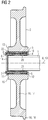
- FIG. 2 Cut as a side elevation and shown in detail, a second exemplary embodiment variant of a wheel set according to the invention is structurally and functionally similar to that of the first exemplary embodiment variant, which is shown in FIG Fig. 1 is shown trained.
- the same reference numerals are therefore used to a large extent.
- end cap 14 is connected (e.g. screwed) to the first wheel 2 or to the wheel set shaft 1 instead of to the first tensioning element 3.
- the end cap 14 shields the first tensioning element 3 and the wheelset shaft 1 on the end face, it being conceivable according to the invention that the end cap 14 also extends over the first wheel 2.
Landscapes
- Engineering & Computer Science (AREA)
- Mechanical Engineering (AREA)
- Gears, Cams (AREA)
- Tires In General (AREA)
Abstract
Um vorteilhafte Konstruktionsbedingungen zu schaffen, wird vorgeschlagen, dass zumindest zwischen dem ersten Rad (2) und der zumindest einen Radsatzwelle (1) ein erstes Spannelement (3) angeordnet ist, mittels welchem das erste Rad (2) lösbar mit der zumindest einen Radsatzwelle (1) verbunden ist.
Description
- Die Erfindung betrifft einen Radsatz für ein Schienenfahrzeug, mit zumindest einer Radsatzwelle sowie mit einem ersten Rad und einem zweiten Rad.
- Zwischen Rädern und Radsatzwellen von Schienenfahrzeugen sind häufig Längspresssitze vorgesehen. Derartig mit Radsatzwellen verbundene Räder müssen für bestimmte Wartungs- und Instandhaltungsmaßnahmen (z.B. für einen Tausch von Rädern, wenn diese entsprechende Verschleiß-Betriebsgrenzmaße erreicht haben) von den Radsatzwellen ab- und aufgepresst werden. Für ein Abpressen eines verschlissenen Rads eines Radsatzes eines Fahrwerks von einer Radsatzwelle und eines Aufpressens eines neuen Rads auf die Radsatzwelle muss der Radsatz aus dem Fahrwerk ausgebaut werden, weshalb ein Rädertausch einen besonders hohen Demontage- und Montageaufwand erfordert bzw. einen großen Zeitbedarf aufweist.
- Aus dem Stand der Technik ist beispielsweise die
RU 91 703 U1
Dieser Ansatz weist in seiner bekannten Form den Nachteil auf, dass zur Demontage und Montage der Räder Ab- und Aufpressvorgänge erforderlich sind. - Weiterhin zeigt die
WO 2018/197581 A1 ein Rad für Schienenfahrzeuge, bei welchem zwischen einer Radnabe und einem Radkörper, der einen Radsteg und einen Spurkranz aufweist, eine Verzahnung angeordnet ist. Zwischen der Radnabe und einer Radsatzwelle ist ein zylindrischer Presssitz vorgesehen.
Dieser Ansatz weist in seiner bekannten Form den Nachteil auf, dass zwar der Radkörper mit geringem Aufwand von der Radnabe gelöst bzw. mit dieser verbunden werden kann, jedoch für eine Demontage und Montage der Radnabe von und auf der Radsatzwelle Presswerkzeuge erforderlich sind. - Der Erfindung liegt daher die Aufgabe zugrunde, einen gegenüber dem Stand der Technik weiterentwickelten Radsatz anzugeben, bei welchem ein Rädertausch einen besonders geringen Aufwand erfordert.
- Erfindungsgemäß wird diese Aufgabe gelöst mit einem Radsatz der eingangs genannten Art, bei dem zumindest zwischen dem ersten Rad und der zumindest einen Radsatzwelle ein erstes Spannelement angeordnet ist, mittels welchem das erste Rad lösbar mit der zumindest einen Radsatzwelle verbunden ist. Dadurch wird ein Demontage- und Montageaufwand des ersten Rads reduziert. Ist der erfindungsgemäße Radsatz mit einem Fahrwerk eines Schienenfahrzeugs verbunden, so ist für eine Demontage bzw. Montage des ersten Rads von der bzw. auf die Radsatzwelle kein Ausbau bzw. Einbau des Radsatzes aus dem bzw. in das Fahrwerk notwendig. Weiterhin sind zur Demontage bzw. Montage des ersten Rads von der bzw. auf die Radsatzwelle keine Radsatzpressvorrichtungen erforderlich, weshalb eine Radsatzmontage-Infrastruktur einfach ausgeführt sein kann.
Aufgrund des verringerten Demontage- und Montageaufwands für das erste Rad verringert sich ein Zeitbedarf für einen Rädertausch an einem innengelagerten Fahrwerk von ca. 210 min auf ca. 45 min.
Weiterhin werden durch einen Entfall von Ab- bzw. Aufpressvorgängen des ersten Rads von der bzw. auf die Radsatzwelle Risiken in Bezug auf eine mögliche Beschädigung der Radsatzwelle aufgrund der Ab- und Aufpressvorgänge gesenkt.
Ferner können aufgrund des ersten Spannelements Anforderungen an Oberflächengüten und Toleranzen der Radsatzwelle und des ersten Rads geringer angesetzt werden als dies für Pressverbände zwischen Radsatzwellen und Rädern vorgesehen sein muss. - Eine vorteilhafte Lösung wird erzielt, wenn das erste Spannelement einen Rücksprung bezüglich einer Radnaben-Stirnseite bildend auf der zumindest einen Radsatzwelle angeordnet ist.
Durch diese Maßnahme sind aus dem ersten Spannelement ragende Spanneinrichtungen (z.B. Schrauben mit ihren Schraubenköpfen) vor mechanischen Einwirkungen und Beschädigungen geschützt. - Es ist günstig, wenn das erste Spannelement als integraler Teil des ersten Rads ausgebildet ist.
Durch diese Maßnahme wird eine zusätzliche Demontage- und Montageerleichterung des ersten Rads von und auf der Radsatzwelle erzielt. - Eine vorteilhafte Ausgestaltung erhält man, wenn das erste Spannelement und die zumindest eine Radsatzwelle stirnseitig mittels einer lösbar mit der zumindest einen Radsatzwelle, mit dem ersten Rad oder mit dem ersten Spannelement verbundenen Endkappe abgeschirmt sind.
Durch diese Maßnahme wird ein Schutz des ersten Spannelements und der Radsatzwelle vor Umgebungseinflüssen (Feuchtigkeit, Spritzwasser, Eis, Schnee und Partikel etc.) erzielt. Dieser Schutz ist insbesondere dann günstig, wenn die Radsatzwelle als Hohlwelle ausgebildet ist. - Nachfolgend wird die Erfindung anhand von Ausführungsbeispielen näher erläutert.
- Es zeigen beispielhaft:
- Fig. 1:
- Einen Seitenriss einer ersten beispielhaften Ausführungsvariante eines erfindungsgemäßen Radsatzes in Schnittdarstellung, bei welchem zwischen einem ersten Rad und einer Radsatzwelle ein erstes Spannelement vorgesehen ist, und
- Fig. 2:
- Einen Seitenriss einer zweiten beispielhaften Ausführungsvariante eines erfindungsgemäßen Radsatzes in Schnittdarstellung, bei welchem zwischen einem ersten Rad und einer Radsatzwelle ein erstes Spannelement vorgesehen ist, wobei die Radsatzwelle und das erste Spannelement stirnseitig mittels einer Endkappe abgedeckt sind.
-
Fig. 1 zeigt einen Seitenriss eines Ausschnitts aus einer ersten beispielhaften Ausführungsvariante eines erfindungsgemäßen Radsatzes eines Schienenfahrzeugs in geschnittener Darstellung. Der Radsatz weist eine Radsatzwelle 1 sowie ein erstes Rad 2 und ein nicht dargestelltes zweites Rad auf, welche mit der Radsatzwelle 1 verbunden sind.
Weiterhin sind mit der Radsatzwelle 1 ein erstes Radsatzlager mit einem ersten Radsatzlagergehäuse und ein zweites Radsatzlager mit einem zweiten Radsatzlagergehäuse, welche nicht gezeigt sind, verbunden. Das erste Radsatzlager und das zweite Radsatzlager sind innerhalb eines von dem ersten Rad 2 und dem zweiten Rad begrenzten Bereichs auf der Radsatzwelle 1 angeordnet.
Über das erste Radsatzlagergehäuse und das zweite Radsatzlagergehäuse ist der Radsatz mit einem nicht dargestellten Fahrwerksrahmen eines innengelagerten Fahrwerks des Schienenfahrzeugs gekoppelt. - Das erste Rad 2 umfasst eine Radnabe 15 sowie einen Radkörper 16, welcher einen Radsteg 17 sowie einen Spurkranz 18 aufweist.
Zwischen der Radsatzwelle 1 und dem ersten Rad 2 ist ein zylindrisches erstes Spannelement 3 angeordnet. Dieses erste Spannelement 3 weist eine Spannelement-Längsachse 8 auf, welche in einer Radsatz-Längsachse 19 verläuft. In einer ersten Bohrung 4 des ersten Spannelements 3 ist eine erste Schraube 6, welche als Sechskantschraube ausgebildet ist, angeordnet. Um die erste Schraube 6 sind eine erste Keilhülse 9 und eine zweite Keilhülse 10 angeordnet. Eine erste Schrauben-Längsachse 20 verläuft parallel zu der Spannelement-Längsachse 8 bzw. zu der Radsatz-Längsachse 19. In einer zweiten Bohrung 5 des ersten Spannelements 3 ist eine zweite Schraube 7, welche als Sechskantschraube ausgebildet ist, angeordnet. Um die zweite Schraube 7 sind eine dritte Keilhülse 11 und eine vierte Keilhülse 12 angeordnet. Eine zweite Schrauben-Längsachse 21 verläuft parallel zu der Spannelement-Längsachse 8 bzw. zu der Radsatz-Längsachse 19.
In nicht sichtbaren weiteren Bohrungen bzw. weiteren Keilhülsen des ersten Spannelements 3 sind nicht sichtbare weitere Schrauben vorgesehen.
Insgesamt weist das erste Spannelement 3 zwölf Bohrungen und Schrauben sowie vierundzwanzig Keilhülsen auf, welche konstruktiv entsprechend der erste Bohrung 4, der ersten Schraube 6, der ersten Keilhülse 9 sowie der zweiten Keilhülse 10 ausgeführt sind und entlang eines Umfangs einer Stirnfläche des ersten Spannelements 3 auf bzw. in dem ersten Spannelement 3 angeordnet sind. - Das erste Spannelement 3 ist in die Radnabe 15 des ersten Rads 2 eingepresst und, vor einem Anziehen der ersten Schraube 6, der zweiten Schraube 7 und der weiteren Schrauben, mit dem ersten Rad 2 auf die Radsatzwelle 1 aufgeschoben bzw. verschiebbar auf der Radsatzwelle 1 angeordnet, wobei zwischen der Radsatzwelle 1 und dem ersten Spannelement 3 eine Übergangspassung vorgesehen ist. Für ein Aufschieben des ersten Spannelements 3 auf die Radsatzwelle 1 ist daher keine Radsatzpresse erforderlich.
Die Radsatzwelle 1 weist einen entsprechenden, nicht dargestellten Sitz, bzw. eine Schulter auf, um das erste Spannelement 3 mit dem ersten Rad 2 auf der Radsatzwelle 1 zu positionieren. Das erste Spannelement 3 ist, bezogen auf eine Radnaben-Stirnseite 13, in Richtung einer Radsatzmitte versetzt angeordnet, d.h. bildet bezüglich der Radnaben-Stirnseite 13 einen Rücksprung, wodurch Schraubenköpfe der ersten Schraube 6, der zweiten Schraube 7 und der weiteren Schrauben vor Beschädigungen geschützt sind. - Die erste Bohrung 4, die zweite Bohrung 5, die weiteren Bohrungen sowie die erste Keilhülse 9, die zweite Keilhülse 10, die dritte Keilhülse 11, die vierte Keilhülse 12 und die weiteren Keilhülsen weisen nicht gezeigte Innengewinde auf, über welche die erste Schraube 6, die zweite Schraube 7 sowie die weiteren Schrauben in einem in
Fig. 1 gezeigten Montagezustand in dem ersten Spannelement 3 angezogen sind. Dadurch bzw. aufgrund einer entsprechenden Keilwirkung ist das erste Spannelement 3 mit der Radsatzwelle 1 und dem ersten Rad 2 verspannt. Aufgrund eines entsprechenden Fugendrucks zwischen dem ersten Spannelement 3 und der Radsatzwelle 1 einerseits sowie dem ersten Rad 2 andererseits erfolgt eine sichere Momenten- und Kraftübertragung zwischen der Radsatzwelle 1 und dem ersten Rad 2.
Aufgrund des ersten Spannelements 3 ist das erste Rad 2 lösbar mit der Radsatzwelle 1 verbunden. Für ein Lösen des ersten Spannelements 3 bzw. des ersten Rads 2 müssen lediglich die erste Schraube 6, die zweite Schraube 7 sowie die weiteren Schrauben gelöst werden. Danach können das erste Rad 2 und das erste Spannelement 3 von der Radsatzwelle 1 abgezogen werden, wofür wiederum keine Radsatzpresse erforderlich ist. - In jener in
Fig. 1 dargestellten ersten Ausführungsvariante eines erfindungsgemäßen Radsatzes ist das erste Spannelement 3 in das erste Rad 2 eingepresst, d.h. kraftschlüssig mit dem ersten Rad 2 verbunden. Erfindungsgemäß ist es jedoch auch vorstellbar, dass das erste Spannelement 3 bzw. ein Außenring 22 des ersten Spannelements 3 stoffschlüssig mit dem ersten Rad 2 bzw. der Radnabe 15 verbunden ist. Weiterhin ist es denkbar, das erste Spannelement 3 bzw. dessen Außenring 22 als integralen Teil des ersten Rads 2 bzw. der Radnabe 15 auszubilden, d.h. das erste Rad 2 und das erste Spannelement 3 einstückig auszuführen. - Das erste Rad 2 ist als einstückiges Vollrad ausgebildet. Erfindungsgemäß kann das erste Rad jedoch auch als Radreifen-Rad oder als Rad, bei welchem der Radkörper 16 von der Radnabe 15 lösbar ist (z.B. über eine Verzahnung zwischen dem Radkörper 16 und der Radnabe 15) etc. ausgeführt sein. Zwischen der Radsatzwelle 1 und dem zweiten Rad ist ein nicht gezeigtes zweites Spannelement vorgesehen, welches konstruktiv, funktional, sowie im Hinblick auf seine Verbindungstechnik gleich wie das erste Spannelement 3 ausgebildet ist.
-
Fig. 1 zeigt einen Radsatz mit durchgehender Verbindung zwischen dem ersten Rad 2 und dem zweiten Rad. Erfindungsgemäß ist es jedoch auch vorstellbar, dass der Radsatz in einer Weise ausgebildet ist, dass eine erste Radsatzwelle mit dem ersten Rad 2 in einer ersten Achsbrücke oder einem ersten Radkasten des Schienenfahrzeugs drehbar gelagert ist und eine zweite Radsatzwelle mit dem zweiten Rad in einer zweiten Achsbrücke oder einem zweiten Radkasten des Schienenfahrzeugs, wobei zwischen der ersten Radsatzwelle und dem ersten Rad 2 das erste Spannelement 3 angeordnet ist und zwischen der zweiten Radsatzwelle und dem zweiten Rad das zweite Spannelement. - Eine in
Fig. 2 als Seitenriss geschnitten und ausschnittsweise dargestellte zweite beispielhafte Ausführungsvariante eines erfindungsgemäßen Radsatzes ist konstruktiv und funktional ähnlich jener ersten beispielhaften Ausführungsvariante, welche inFig. 1 gezeigt ist, ausgebildet. Es werden daher weitgehend gleiche Bezugszeichen verwendet. - Im Unterschied zu der ersten beispielhaften Ausführungsvariante eines erfindungsgemäßen Radsatzes von
Fig. 1 zeigtFig. 2 einen Radsatz, welcher eine als Hohlwelle ausgebildete Radsatzwelle 1 aufweist. Zwischen der Radsatzwelle 1 und einem ersten Rad 2 ist ein erstes Spannelement 3 angeordnet und mit der Radsatzwelle 1 sowie mit dem ersten Rad 2 mittels einer ersten Schraube 6, einer zweiten Schraube 7 sowie weiterer Schrauben verspannt.
Das erste Spannelement 3 schließt bündig mit einer Radnaben-Stirnseite 13 ab und ist von einer Endkappe 14 abgedeckt. Die Endkappe 14 ist mittels der ersten Schraube 6, der zweiten Schraube 7 sowie der weiteren Schrauben mit dem ersten Spannelement 3 verschraubt und somit lösbar mit dem ersten Spannelement 3 verbunden. Zwischen der Endkappe 14 und dem ersten Spannelement 3 ist eine nicht dargestellte Gummidichtung vorgesehen.
Erfindungsgemäß ist es jedoch auch vorstellbar, dass das erste Spannelement 3 bezüglich der Radnaben-Stirnseite 13 in Richtung einer Radsatzmitte versetzt angeordnet ist und zwischen dem ersten Spannelement 3 und der Endkappe 14 Distanzhülsen vorgesehen sind. - Erfindungsgemäß ist es weiterhin vorstellbar, dass die Endkappe 14 anstatt mit dem ersten Spannelement 3 beispielsweise mit dem ersten Rad 2 oder mit der Radsatzwelle 1 verbunden (z.B. verschraubt) ist.
- Die Endkappe 14 schirmt das erste Spannelement 3 sowie die Radsatzwelle 1 stirnseitig ab, wobei es erfindungsgemäß denkbar ist, dass sich die Endkappe 14 auch über das erste Rad 2 erstreckt.
-
- 1
- Radsatzwelle
- 2
- Erstes Rad
- 3
- Erstes Spannelement
- 4
- Erste Bohrung
- 5
- Zweite Bohrung
- 6
- Erste Schraube
- 7
- Zweite Schraube
- 8
- Spannelement-Längsachse
- 9
- Erste Keilhülse
- 10
- Zweite Keilhülse
- 11
- Dritte Keilhülse
- 12
- Vierte Keilhülse
- 13
- Radnaben-Stirnseite
- 14
- Endkappe
- 15
- Radnabe
- 16
- Radkörper
- 17
- Radsteg
- 18
- Spurkranz
- 19
- Radsatz-Längsachse
- 20
- Erste Schrauben-Längsachse
- 21
- Zweite Schrauben-Längsachse
- 22
- Außenring
Claims (7)
- Radsatz für ein Schienenfahrzeug, mit zumindest einer Radsatzwelle sowie mit einem ersten Rad und einem zweiten Rad, dadurch gekennzeichnet,
dass zumindest zwischen dem ersten Rad (2) und der zumindest einen Radsatzwelle (1) ein erstes Spannelement (3) angeordnet ist, mittels welchem das erste Rad (2) lösbar mit der zumindest einen Radsatzwelle (1) verbunden ist. - Radsatz nach Anspruch 1, dadurch gekennzeichnet, dass das erste Spannelement (3) mittels einer in einer ersten Bohrung (4) angeordneten ersten Schraube (6) sowie in weiteren Bohrungen angeordneten weiteren Schrauben, welche parallel zu einer Spannelement-Längsachse (8) verlaufen, mit dem ersten Rad (2) und der zumindest einen Radsatzwelle (1) verspannt ist.
- Radsatz nach Anspruch 2, dadurch gekennzeichnet, dass zumindest um die erste Schraube (6) zumindest eine erste Keilhülse (9) angeordnet ist.
- Radsatz nach einem der Ansprüche 1 bis 3, dadurch gekennzeichnet, dass das erste Spannelement (3) einen Rücksprung bezüglich einer Radnaben-Stirnseite (13) bildend auf der zumindest einen Radsatzwelle (1) angeordnet ist.
- Radsatz nach einem der Ansprüche 1 bis 4, dadurch gekennzeichnet, dass das erste Spannelement (3) als integraler Teil des ersten Rads (2) ausgebildet ist.
- Radsatz nach einem der Ansprüche 1 bis 5, dadurch gekennzeichnet, dass das erste Spannelement (3) und die zumindest eine Radsatzwelle (1) stirnseitig mittels einer lösbar mit der zumindest einen Radsatzwelle (1), mit dem ersten Rad (2) oder mit dem ersten Spannelement (3) verbundenen Endkappe (14) abgeschirmt sind.
- Fahrwerk mit zumindest einem Radsatz nach einem der Ansprüche 1 bis 6.
Applications Claiming Priority (1)
| Application Number | Priority Date | Filing Date | Title |
|---|---|---|---|
| ATA51101/2018A AT521883B1 (de) | 2018-12-12 | 2018-12-12 | Radsatz für ein Schienenfahrzeug |
Publications (2)
| Publication Number | Publication Date |
|---|---|
| EP3666544A1 true EP3666544A1 (de) | 2020-06-17 |
| EP3666544B1 EP3666544B1 (de) | 2022-05-25 |
Family
ID=68840969
Family Applications (1)
| Application Number | Title | Priority Date | Filing Date |
|---|---|---|---|
| EP19214543.1A Active EP3666544B1 (de) | 2018-12-12 | 2019-12-09 | Radsatz für ein schienenfahrzeug |
Country Status (2)
| Country | Link |
|---|---|
| EP (1) | EP3666544B1 (de) |
| AT (1) | AT521883B1 (de) |
Cited By (1)
| Publication number | Priority date | Publication date | Assignee | Title |
|---|---|---|---|---|
| EP3960490A1 (de) * | 2020-08-28 | 2022-03-02 | Siemens Mobility Austria GmbH | Radsatzlager, radsatz und fahrwerk für fahrzeuge |
Citations (11)
| Publication number | Priority date | Publication date | Assignee | Title |
|---|---|---|---|---|
| GB239931A (en) * | 1924-06-18 | 1925-09-18 | Stephen Evans Alley | Improvements in or relating to the axles and running-wheels of railway vehicles and the like |
| GB403076A (en) * | 1932-06-15 | 1933-12-12 | Franz Kruckenberg | Fastening for the wheels of railway vehicles |
| DE948609C (de) * | 1956-08-02 | Krefeld-Uerdingen Rudolf Ahrens | Lagerung der losen Räder auf den festen Tragachsen von Schienenfahrzeugen | |
| GB1443767A (en) * | 1972-12-19 | 1976-07-28 | Asea Ab | Mounting of wheels on axles |
| CN2088052U (zh) * | 1991-05-15 | 1991-11-06 | 席庶林 | 弹性环式铁路车辆轮对 |
| RU91703U1 (ru) | 2009-10-08 | 2010-02-27 | Открытое Акционерное Общество "Российские Железные Дороги" | Моторная колесная пара высокоскоростного железнодорожного транспортного средства |
| CN202368267U (zh) * | 2011-12-26 | 2012-08-08 | 南车四方车辆有限公司 | 轮对组成及轨道列车 |
| CN202911466U (zh) * | 2012-11-30 | 2013-05-01 | 南车四方车辆有限公司 | 导向轮及铁路公路两用车 |
| PL397318A1 (pl) * | 2011-12-09 | 2013-06-10 | Urzadzenia I Konstrukcje Spólka Akcyjna | Zestaw kolowy kopalnianego pojazdu szynowego |
| WO2018197581A1 (de) | 2017-04-27 | 2018-11-01 | Siemens Ag Österreich | Rad für schienenfahrzeuge |
| EP3560729A1 (de) * | 2018-04-26 | 2019-10-30 | Penn Machine Company LLC | Mechanisch befestigte radanordnung |
-
2018
- 2018-12-12 AT ATA51101/2018A patent/AT521883B1/de not_active IP Right Cessation
-
2019
- 2019-12-09 EP EP19214543.1A patent/EP3666544B1/de active Active
Patent Citations (11)
| Publication number | Priority date | Publication date | Assignee | Title |
|---|---|---|---|---|
| DE948609C (de) * | 1956-08-02 | Krefeld-Uerdingen Rudolf Ahrens | Lagerung der losen Räder auf den festen Tragachsen von Schienenfahrzeugen | |
| GB239931A (en) * | 1924-06-18 | 1925-09-18 | Stephen Evans Alley | Improvements in or relating to the axles and running-wheels of railway vehicles and the like |
| GB403076A (en) * | 1932-06-15 | 1933-12-12 | Franz Kruckenberg | Fastening for the wheels of railway vehicles |
| GB1443767A (en) * | 1972-12-19 | 1976-07-28 | Asea Ab | Mounting of wheels on axles |
| CN2088052U (zh) * | 1991-05-15 | 1991-11-06 | 席庶林 | 弹性环式铁路车辆轮对 |
| RU91703U1 (ru) | 2009-10-08 | 2010-02-27 | Открытое Акционерное Общество "Российские Железные Дороги" | Моторная колесная пара высокоскоростного железнодорожного транспортного средства |
| PL397318A1 (pl) * | 2011-12-09 | 2013-06-10 | Urzadzenia I Konstrukcje Spólka Akcyjna | Zestaw kolowy kopalnianego pojazdu szynowego |
| CN202368267U (zh) * | 2011-12-26 | 2012-08-08 | 南车四方车辆有限公司 | 轮对组成及轨道列车 |
| CN202911466U (zh) * | 2012-11-30 | 2013-05-01 | 南车四方车辆有限公司 | 导向轮及铁路公路两用车 |
| WO2018197581A1 (de) | 2017-04-27 | 2018-11-01 | Siemens Ag Österreich | Rad für schienenfahrzeuge |
| EP3560729A1 (de) * | 2018-04-26 | 2019-10-30 | Penn Machine Company LLC | Mechanisch befestigte radanordnung |
Cited By (1)
| Publication number | Priority date | Publication date | Assignee | Title |
|---|---|---|---|---|
| EP3960490A1 (de) * | 2020-08-28 | 2022-03-02 | Siemens Mobility Austria GmbH | Radsatzlager, radsatz und fahrwerk für fahrzeuge |
Also Published As
| Publication number | Publication date |
|---|---|
| EP3666544B1 (de) | 2022-05-25 |
| AT521883A1 (de) | 2020-06-15 |
| AT521883B1 (de) | 2020-12-15 |
Similar Documents
| Publication | Publication Date | Title |
|---|---|---|
| EP2126353B1 (de) | Verbindung von bauteilen einer windenenergieanlage sowie verfahren | |
| EP2838743B1 (de) | Gummilageranbindung | |
| AT519892B1 (de) | Rad für Fahrzeuge | |
| EP0047933B1 (de) | Verfahren zur Herstellung eines geteilten aussenverzahnten Stirnrades und zur Montage desselben auf einer Welle | |
| EP3666544B1 (de) | Radsatz für ein schienenfahrzeug | |
| EP3390250B1 (de) | Laufrolle, laufrolleneinrichtung, gelenkkette, sowie die verwendung einer gelenkkette als förderkette | |
| DE4434102B4 (de) | Nabenanordnung | |
| DE102010039266A1 (de) | Anordnung zur Befestigung eines aus einem Leichtmetallwerkstoff bestehenden Sekundärelements an einem Primärelement | |
| EP3461714B1 (de) | Fahrwerk für ein schienenfahrzeug | |
| EP3504097B1 (de) | Rad-anordnung für ein schienenfahrzeug | |
| EP2045043A2 (de) | Radnabendemontagevorrichtung | |
| DE102019212725A1 (de) | Schwenklager mit einem an diesem befestigten Gelenk | |
| DE102018129285A1 (de) | Radlager für ein Kraftfahrzeug | |
| AT524445B1 (de) | Führungsvorrichtung für Fahrwerke, Fahrwerk und Verfahren zur Montage einer Führungsvorrichtung in ein Fahrwerk | |
| EP1003650A1 (de) | Vorderachsabtrieb eines automatgetriebes | |
| EP3323629B1 (de) | Radlageranordnung | |
| EP3960490A1 (de) | Radsatzlager, radsatz und fahrwerk für fahrzeuge | |
| EP3686076A1 (de) | Getriebegehäuse und anordnung zur abstützung eines getriebes | |
| DE102017213273B4 (de) | Radnabenlagereinheit eines Kraftfahrzeugs | |
| AT523026B1 (de) | Fahrwerk für ein Schienenfahrzeug | |
| EP0940328B1 (de) | Sattelkupplung zur Direktmontage auf einem Hilfsrahmen | |
| DE102014005292A1 (de) | Kraftfahrzeug | |
| DE102012002716B3 (de) | Schienenrad | |
| WO2017121536A1 (de) | Radsatzwellenanordnung eines schienenfahrzeugs | |
| DE102015204158A1 (de) | Bolzenkäfig mit Verbindungsmutter |
Legal Events
| Date | Code | Title | Description |
|---|---|---|---|
| PUAI | Public reference made under article 153(3) epc to a published international application that has entered the european phase |
Free format text: ORIGINAL CODE: 0009012 |
|
| STAA | Information on the status of an ep patent application or granted ep patent |
Free format text: STATUS: THE APPLICATION HAS BEEN PUBLISHED |
|
| AK | Designated contracting states |
Kind code of ref document: A1 Designated state(s): AL AT BE BG CH CY CZ DE DK EE ES FI FR GB GR HR HU IE IS IT LI LT LU LV MC MK MT NL NO PL PT RO RS SE SI SK SM TR |
|
| AX | Request for extension of the european patent |
Extension state: BA ME |
|
| STAA | Information on the status of an ep patent application or granted ep patent |
Free format text: STATUS: REQUEST FOR EXAMINATION WAS MADE |
|
| 17P | Request for examination filed |
Effective date: 20201214 |
|
| RBV | Designated contracting states (corrected) |
Designated state(s): AL AT BE BG CH CY CZ DE DK EE ES FI FR GB GR HR HU IE IS IT LI LT LU LV MC MK MT NL NO PL PT RO RS SE SI SK SM TR |
|
| GRAP | Despatch of communication of intention to grant a patent |
Free format text: ORIGINAL CODE: EPIDOSNIGR1 |
|
| STAA | Information on the status of an ep patent application or granted ep patent |
Free format text: STATUS: GRANT OF PATENT IS INTENDED |
|
| INTG | Intention to grant announced |
Effective date: 20220110 |
|
| RAP3 | Party data changed (applicant data changed or rights of an application transferred) |
Owner name: SIEMENS MOBILITY AUSTRIA GMBH |
|
| GRAS | Grant fee paid |
Free format text: ORIGINAL CODE: EPIDOSNIGR3 |
|
| GRAA | (expected) grant |
Free format text: ORIGINAL CODE: 0009210 |
|
| STAA | Information on the status of an ep patent application or granted ep patent |
Free format text: STATUS: THE PATENT HAS BEEN GRANTED |
|
| AK | Designated contracting states |
Kind code of ref document: B1 Designated state(s): AL AT BE BG CH CY CZ DE DK EE ES FI FR GB GR HR HU IE IS IT LI LT LU LV MC MK MT NL NO PL PT RO RS SE SI SK SM TR |
|
| REG | Reference to a national code |
Ref country code: GB Ref legal event code: FG4D Free format text: NOT ENGLISH |
|
| REG | Reference to a national code |
Ref country code: CH Ref legal event code: EP |
|
| REG | Reference to a national code |
Ref country code: AT Ref legal event code: REF Ref document number: 1494117 Country of ref document: AT Kind code of ref document: T Effective date: 20220615 Ref country code: DE Ref legal event code: R096 Ref document number: 502019004450 Country of ref document: DE |
|
| REG | Reference to a national code |
Ref country code: IE Ref legal event code: FG4D Free format text: LANGUAGE OF EP DOCUMENT: GERMAN |
|
| REG | Reference to a national code |
Ref country code: LT Ref legal event code: MG9D |
|
| REG | Reference to a national code |
Ref country code: NL Ref legal event code: MP Effective date: 20220525 |
|
| PG25 | Lapsed in a contracting state [announced via postgrant information from national office to epo] |
Ref country code: SE Free format text: LAPSE BECAUSE OF FAILURE TO SUBMIT A TRANSLATION OF THE DESCRIPTION OR TO PAY THE FEE WITHIN THE PRESCRIBED TIME-LIMIT Effective date: 20220525 Ref country code: PT Free format text: LAPSE BECAUSE OF FAILURE TO SUBMIT A TRANSLATION OF THE DESCRIPTION OR TO PAY THE FEE WITHIN THE PRESCRIBED TIME-LIMIT Effective date: 20220926 Ref country code: NO Free format text: LAPSE BECAUSE OF FAILURE TO SUBMIT A TRANSLATION OF THE DESCRIPTION OR TO PAY THE FEE WITHIN THE PRESCRIBED TIME-LIMIT Effective date: 20220825 Ref country code: NL Free format text: LAPSE BECAUSE OF FAILURE TO SUBMIT A TRANSLATION OF THE DESCRIPTION OR TO PAY THE FEE WITHIN THE PRESCRIBED TIME-LIMIT Effective date: 20220525 Ref country code: LT Free format text: LAPSE BECAUSE OF FAILURE TO SUBMIT A TRANSLATION OF THE DESCRIPTION OR TO PAY THE FEE WITHIN THE PRESCRIBED TIME-LIMIT Effective date: 20220525 Ref country code: HR Free format text: LAPSE BECAUSE OF FAILURE TO SUBMIT A TRANSLATION OF THE DESCRIPTION OR TO PAY THE FEE WITHIN THE PRESCRIBED TIME-LIMIT Effective date: 20220525 Ref country code: GR Free format text: LAPSE BECAUSE OF FAILURE TO SUBMIT A TRANSLATION OF THE DESCRIPTION OR TO PAY THE FEE WITHIN THE PRESCRIBED TIME-LIMIT Effective date: 20220826 Ref country code: FI Free format text: LAPSE BECAUSE OF FAILURE TO SUBMIT A TRANSLATION OF THE DESCRIPTION OR TO PAY THE FEE WITHIN THE PRESCRIBED TIME-LIMIT Effective date: 20220525 Ref country code: ES Free format text: LAPSE BECAUSE OF FAILURE TO SUBMIT A TRANSLATION OF THE DESCRIPTION OR TO PAY THE FEE WITHIN THE PRESCRIBED TIME-LIMIT Effective date: 20220525 Ref country code: BG Free format text: LAPSE BECAUSE OF FAILURE TO SUBMIT A TRANSLATION OF THE DESCRIPTION OR TO PAY THE FEE WITHIN THE PRESCRIBED TIME-LIMIT Effective date: 20220825 |
|
| PG25 | Lapsed in a contracting state [announced via postgrant information from national office to epo] |
Ref country code: RS Free format text: LAPSE BECAUSE OF FAILURE TO SUBMIT A TRANSLATION OF THE DESCRIPTION OR TO PAY THE FEE WITHIN THE PRESCRIBED TIME-LIMIT Effective date: 20220525 Ref country code: PL Free format text: LAPSE BECAUSE OF FAILURE TO SUBMIT A TRANSLATION OF THE DESCRIPTION OR TO PAY THE FEE WITHIN THE PRESCRIBED TIME-LIMIT Effective date: 20220525 Ref country code: LV Free format text: LAPSE BECAUSE OF FAILURE TO SUBMIT A TRANSLATION OF THE DESCRIPTION OR TO PAY THE FEE WITHIN THE PRESCRIBED TIME-LIMIT Effective date: 20220525 Ref country code: IS Free format text: LAPSE BECAUSE OF FAILURE TO SUBMIT A TRANSLATION OF THE DESCRIPTION OR TO PAY THE FEE WITHIN THE PRESCRIBED TIME-LIMIT Effective date: 20220925 |
|
| PG25 | Lapsed in a contracting state [announced via postgrant information from national office to epo] |
Ref country code: SM Free format text: LAPSE BECAUSE OF FAILURE TO SUBMIT A TRANSLATION OF THE DESCRIPTION OR TO PAY THE FEE WITHIN THE PRESCRIBED TIME-LIMIT Effective date: 20220525 Ref country code: SK Free format text: LAPSE BECAUSE OF FAILURE TO SUBMIT A TRANSLATION OF THE DESCRIPTION OR TO PAY THE FEE WITHIN THE PRESCRIBED TIME-LIMIT Effective date: 20220525 Ref country code: RO Free format text: LAPSE BECAUSE OF FAILURE TO SUBMIT A TRANSLATION OF THE DESCRIPTION OR TO PAY THE FEE WITHIN THE PRESCRIBED TIME-LIMIT Effective date: 20220525 Ref country code: EE Free format text: LAPSE BECAUSE OF FAILURE TO SUBMIT A TRANSLATION OF THE DESCRIPTION OR TO PAY THE FEE WITHIN THE PRESCRIBED TIME-LIMIT Effective date: 20220525 Ref country code: DK Free format text: LAPSE BECAUSE OF FAILURE TO SUBMIT A TRANSLATION OF THE DESCRIPTION OR TO PAY THE FEE WITHIN THE PRESCRIBED TIME-LIMIT Effective date: 20220525 Ref country code: CZ Free format text: LAPSE BECAUSE OF FAILURE TO SUBMIT A TRANSLATION OF THE DESCRIPTION OR TO PAY THE FEE WITHIN THE PRESCRIBED TIME-LIMIT Effective date: 20220525 |
|
| REG | Reference to a national code |
Ref country code: DE Ref legal event code: R097 Ref document number: 502019004450 Country of ref document: DE |
|
| PG25 | Lapsed in a contracting state [announced via postgrant information from national office to epo] |
Ref country code: AL Free format text: LAPSE BECAUSE OF FAILURE TO SUBMIT A TRANSLATION OF THE DESCRIPTION OR TO PAY THE FEE WITHIN THE PRESCRIBED TIME-LIMIT Effective date: 20220525 |
|
| PLBE | No opposition filed within time limit |
Free format text: ORIGINAL CODE: 0009261 |
|
| STAA | Information on the status of an ep patent application or granted ep patent |
Free format text: STATUS: NO OPPOSITION FILED WITHIN TIME LIMIT |
|
| 26N | No opposition filed |
Effective date: 20230228 |
|
| PG25 | Lapsed in a contracting state [announced via postgrant information from national office to epo] |
Ref country code: SI Free format text: LAPSE BECAUSE OF FAILURE TO SUBMIT A TRANSLATION OF THE DESCRIPTION OR TO PAY THE FEE WITHIN THE PRESCRIBED TIME-LIMIT Effective date: 20220525 |
|
| REG | Reference to a national code |
Ref country code: BE Ref legal event code: MM Effective date: 20221231 |
|
| PG25 | Lapsed in a contracting state [announced via postgrant information from national office to epo] |
Ref country code: LU Free format text: LAPSE BECAUSE OF NON-PAYMENT OF DUE FEES Effective date: 20221209 |
|
| PG25 | Lapsed in a contracting state [announced via postgrant information from national office to epo] |
Ref country code: IE Free format text: LAPSE BECAUSE OF NON-PAYMENT OF DUE FEES Effective date: 20221209 |
|
| PG25 | Lapsed in a contracting state [announced via postgrant information from national office to epo] |
Ref country code: BE Free format text: LAPSE BECAUSE OF NON-PAYMENT OF DUE FEES Effective date: 20221231 |
|
| PG25 | Lapsed in a contracting state [announced via postgrant information from national office to epo] |
Ref country code: IT Free format text: LAPSE BECAUSE OF FAILURE TO SUBMIT A TRANSLATION OF THE DESCRIPTION OR TO PAY THE FEE WITHIN THE PRESCRIBED TIME-LIMIT Effective date: 20220525 |
|
| PG25 | Lapsed in a contracting state [announced via postgrant information from national office to epo] |
Ref country code: HU Free format text: LAPSE BECAUSE OF FAILURE TO SUBMIT A TRANSLATION OF THE DESCRIPTION OR TO PAY THE FEE WITHIN THE PRESCRIBED TIME-LIMIT; INVALID AB INITIO Effective date: 20191209 |
|
| PG25 | Lapsed in a contracting state [announced via postgrant information from national office to epo] |
Ref country code: CY Free format text: LAPSE BECAUSE OF FAILURE TO SUBMIT A TRANSLATION OF THE DESCRIPTION OR TO PAY THE FEE WITHIN THE PRESCRIBED TIME-LIMIT Effective date: 20220525 |
|
| PG25 | Lapsed in a contracting state [announced via postgrant information from national office to epo] |
Ref country code: MK Free format text: LAPSE BECAUSE OF FAILURE TO SUBMIT A TRANSLATION OF THE DESCRIPTION OR TO PAY THE FEE WITHIN THE PRESCRIBED TIME-LIMIT Effective date: 20220525 |
|
| PG25 | Lapsed in a contracting state [announced via postgrant information from national office to epo] |
Ref country code: MC Free format text: LAPSE BECAUSE OF FAILURE TO SUBMIT A TRANSLATION OF THE DESCRIPTION OR TO PAY THE FEE WITHIN THE PRESCRIBED TIME-LIMIT Effective date: 20220525 |
|
| PG25 | Lapsed in a contracting state [announced via postgrant information from national office to epo] |
Ref country code: MC Free format text: LAPSE BECAUSE OF FAILURE TO SUBMIT A TRANSLATION OF THE DESCRIPTION OR TO PAY THE FEE WITHIN THE PRESCRIBED TIME-LIMIT Effective date: 20220525 |
|
| PG25 | Lapsed in a contracting state [announced via postgrant information from national office to epo] |
Ref country code: MT Free format text: LAPSE BECAUSE OF FAILURE TO SUBMIT A TRANSLATION OF THE DESCRIPTION OR TO PAY THE FEE WITHIN THE PRESCRIBED TIME-LIMIT Effective date: 20220525 |
|
| PG25 | Lapsed in a contracting state [announced via postgrant information from national office to epo] |
Ref country code: BG Free format text: LAPSE BECAUSE OF FAILURE TO SUBMIT A TRANSLATION OF THE DESCRIPTION OR TO PAY THE FEE WITHIN THE PRESCRIBED TIME-LIMIT Effective date: 20220525 |
|
| PG25 | Lapsed in a contracting state [announced via postgrant information from national office to epo] |
Ref country code: BG Free format text: LAPSE BECAUSE OF FAILURE TO SUBMIT A TRANSLATION OF THE DESCRIPTION OR TO PAY THE FEE WITHIN THE PRESCRIBED TIME-LIMIT Effective date: 20220525 |
|
| PG25 | Lapsed in a contracting state [announced via postgrant information from national office to epo] |
Ref country code: TR Free format text: LAPSE BECAUSE OF FAILURE TO SUBMIT A TRANSLATION OF THE DESCRIPTION OR TO PAY THE FEE WITHIN THE PRESCRIBED TIME-LIMIT Effective date: 20220525 |
|
| PGFP | Annual fee paid to national office [announced via postgrant information from national office to epo] |
Ref country code: AT Payment date: 20251107 Year of fee payment: 7 |
|
| PGFP | Annual fee paid to national office [announced via postgrant information from national office to epo] |
Ref country code: FR Payment date: 20251215 Year of fee payment: 7 |
|
| REG | Reference to a national code |
Ref country code: CH Ref legal event code: U11 Free format text: ST27 STATUS EVENT CODE: U-0-0-U10-U11 (AS PROVIDED BY THE NATIONAL OFFICE) Effective date: 20260310 |
|
| PGFP | Annual fee paid to national office [announced via postgrant information from national office to epo] |
Ref country code: GB Payment date: 20260107 Year of fee payment: 7 |
|
| PGFP | Annual fee paid to national office [announced via postgrant information from national office to epo] |
Ref country code: DE Payment date: 20260219 Year of fee payment: 7 |
|
| PGFP | Annual fee paid to national office [announced via postgrant information from national office to epo] |
Ref country code: CH Payment date: 20260310 Year of fee payment: 7 |