EP3666433B1 - Bohrwerkzeug - Google Patents
Bohrwerkzeug Download PDFInfo
- Publication number
- EP3666433B1 EP3666433B1 EP18212364.6A EP18212364A EP3666433B1 EP 3666433 B1 EP3666433 B1 EP 3666433B1 EP 18212364 A EP18212364 A EP 18212364A EP 3666433 B1 EP3666433 B1 EP 3666433B1
- Authority
- EP
- European Patent Office
- Prior art keywords
- chip space
- drilling tool
- drill
- space extension
- flutes
- Prior art date
- Legal status (The legal status is an assumption and is not a legal conclusion. Google has not performed a legal analysis and makes no representation as to the accuracy of the status listed.)
- Active
Links
Images
Classifications
-
- B—PERFORMING OPERATIONS; TRANSPORTING
- B23—MACHINE TOOLS; METAL-WORKING NOT OTHERWISE PROVIDED FOR
- B23B—TURNING; BORING
- B23B51/00—Tools for drilling machines
- B23B51/02—Twist drills
-
- B—PERFORMING OPERATIONS; TRANSPORTING
- B24—GRINDING; POLISHING
- B24B—MACHINES, DEVICES, OR PROCESSES FOR GRINDING OR POLISHING; DRESSING OR CONDITIONING OF ABRADING SURFACES; FEEDING OF GRINDING, POLISHING, OR LAPPING AGENTS
- B24B19/00—Single-purpose machines or devices for particular grinding operations not covered by any other main group
- B24B19/02—Single-purpose machines or devices for particular grinding operations not covered by any other main group for grinding grooves, e.g. on shafts, in casings, in tubes, homokinetic joint elements
- B24B19/022—Single-purpose machines or devices for particular grinding operations not covered by any other main group for grinding grooves, e.g. on shafts, in casings, in tubes, homokinetic joint elements for helicoidal grooves
-
- B—PERFORMING OPERATIONS; TRANSPORTING
- B24—GRINDING; POLISHING
- B24B—MACHINES, DEVICES, OR PROCESSES FOR GRINDING OR POLISHING; DRESSING OR CONDITIONING OF ABRADING SURFACES; FEEDING OF GRINDING, POLISHING, OR LAPPING AGENTS
- B24B19/00—Single-purpose machines or devices for particular grinding operations not covered by any other main group
- B24B19/02—Single-purpose machines or devices for particular grinding operations not covered by any other main group for grinding grooves, e.g. on shafts, in casings, in tubes, homokinetic joint elements
- B24B19/04—Single-purpose machines or devices for particular grinding operations not covered by any other main group for grinding grooves, e.g. on shafts, in casings, in tubes, homokinetic joint elements for fluting drill shanks
-
- B—PERFORMING OPERATIONS; TRANSPORTING
- B23—MACHINE TOOLS; METAL-WORKING NOT OTHERWISE PROVIDED FOR
- B23B—TURNING; BORING
- B23B2251/00—Details of tools for drilling machines
- B23B2251/40—Flutes, i.e. chip conveying grooves
- B23B2251/406—Flutes, i.e. chip conveying grooves of special form not otherwise provided for
-
- B—PERFORMING OPERATIONS; TRANSPORTING
- B23—MACHINE TOOLS; METAL-WORKING NOT OTHERWISE PROVIDED FOR
- B23B—TURNING; BORING
- B23B2251/00—Details of tools for drilling machines
- B23B2251/44—Margins, i.e. the narrow portion of the land which is not cut away to provide clearance on the circumferential surface
- B23B2251/443—Double margin drills
-
- B—PERFORMING OPERATIONS; TRANSPORTING
- B23—MACHINE TOOLS; METAL-WORKING NOT OTHERWISE PROVIDED FOR
- B23B—TURNING; BORING
- B23B51/00—Tools for drilling machines
- B23B51/06—Drills with lubricating or cooling equipment
Definitions
- the present invention relates to a drilling tool with the features of the preamble of claim 1.
- Generic drilling tools in particular twist drills, comprise a cylindrical base body on which helically shaped webs and flutes are formed between webs.
- the angle at which the flutes are inclined to a central axis of the twist drill is the helix angle (also referred to as helix angle) of the twist drill.
- the helix angle can be variable over the length of the twist drill.
- twist drills have two helical flutes.
- the chip grooves enable chips to be removed.
- Chip space extension created in this way creates additional volume for the collection and removal of chips.
- Chip space expansion generally means that a free cross section of a chip flute is enlarged compared to the actual tool grind.
- the EP1396303A2 (MITSUBISHI MATERIALS CORP - 03/10/2004 ) shows a
- Drilling tool according to the preamble of claim 1 with twisted flutes with webs formed between the flutes and partially having guide chamfers with a web width, with a chip space expansion being introduced at least in sections in at least one of the flutes to enlarge the chip space, the web width being reduced in the area of the chip space expansion is.
- the WO 95/04624 shows a drill with a chip space expansion that increases towards the shaft ("widening of the flute").
- the DE69209034T2 (Sumitomo Electric - 10/02/2002 ) shows a drill with flutes of gradually increasing width towards the shank and gradually decreasing spiral angle.
- the DE69209034T2 (SANDVIK AB - 07/25/1996 ) shows a drill whose flutes transition from a first zone that forms the chips into a second zone that only transports the chips and has a larger width or a larger cross section.
- the object of the present invention is to provide an improved drilling tool.
- the drilling tool according to the invention is designed in such a way that guide chamfers are formed over at least part of the cutting section and the chip space expansion, viewed from the drill end in the direction of the shaft section, only begins after the area of the cutting section on which guide chamfers are formed. It is further provided that the chip space expansion covers a web, so that a web width in the area of the chip space expansion is reduced. In other words, the chip space of the tool is increased at the expense of the web. The web is therefore narrower in the area of the chip space expansion than in a section of the drilling tool in which no chip space expansion is formed.
- Chip space extensions from the prior art are designed, among other things, as local depressions of chip grooves at their base.
- the creation of additional chip space through known chip space expansions is limited in these cases because the supporting cross section of the drilling tool, i.e. the core diameter, is weakened.
- a chip space expansion according to the invention expands a flute laterally by reducing a web width.
- additional chip space can also be created by deepening the flute at its base.
- the chip space expansion according to the invention promotes the removal of chips. The tendency to constipation is reduced.
- Chip space extensions are preferably formed on all flutes of the drilling tool. Of course, it can also be provided to form a chip space expansion on only one chip groove. However, to ensure an even mechanical load on the drilling tool, it is cheaper to provide chip space extensions on all flutes.
- the chips Due to the change in shape of the chip groove due to the chip space expansion according to the invention, the chips experience an acceleration, which promotes chip breakage.
- Acceleration is to be understood as meaning that the chips experience a change in momentum. Due to the inventive design of the chip space expansion, the change in momentum occurs primarily as a change in the direction of movement of the chips, i.e. through a chip deflection.
- a web has a secondary cutting edge on the side in the direction of rotation.
- the reduction in the web width preferably takes place on the side of the web facing away from the secondary cutting edge, so that the shape of the secondary cutting edge remains unaffected by the chip space expansion. This ensures a smooth chip flow.
- the chip space expansion is designed such that only the side of a web facing away from a direction of rotation is covered by the chip space expansion.
- another advantage of the invention is that a significant increase in the chip volume can be achieved within a short distance.
- short path it is meant that the chip space expansion can be realized along a small angular range - based on a course of the helical flutes - or, in other words, within a short distance - based on a longitudinal extent of the drilling tool.
- the chip space expansion preferably increases a groove opening angle of a chip groove.
- the groove opening angle is understood to mean the angle that the opposite flanks of a flute enclose with one another.
- the chip space expansion viewed from the drill face in the direction of the shaft section, only begins at a distance from the drill face.
- the front part of the cutting section has no chip space expansion.
- the expansion of the chip space preferably only begins at a distance from the drill face of greater than or equal to 1 x D, where D is the drill diameter.
- guide chamfers viewed from the drill face in the direction of the shaft section, are formed at a distance from the drill face of less than or equal to 3 x D.
- Two guide chamfers are particularly preferably formed on a web. According to the invention, it is provided that the chip space expansion, viewed from the drill face in the direction of the shaft section, only begins after the area of the cutting section on which guide chamfers are formed. This has the advantage that the webs in the area of the guide chamfers have their original width, which is favorable for guiding or supporting the drill.
- the expansion of the chip space achieved by the chip space expansion increases along the longitudinal axis of the drill.
- the chip space expansion does not have to be constant, but can increase along the longitudinal axis of the drill. For mechanical reasons, it is advantageous if the chip space expansion increases continuously, i.e. not suddenly.
- the increase in the chip space expansion occurs within less than or equal to 360°. This describes the already mentioned characteristic that the chip space expansion reaches the desired level within a short distance. At 360°, within one revolution of a helical flute, the chip space expansion would increase from a starting value to the desired final dimension.
- the chip space expansion can be increased, for example, along a projected distance of less than or equal to 2.5 x the drill diameter D.
- the chip space expansion increases along a first projected distance in the direction of the shaft section and then remains constant along a second projected distance in the direction of the shaft section.
- the chip space expansion is preferably designed as a recess. This means that the chip space expansion is preferably introduced by grinding. Alternatively, material could be removed by other methods, such as laser ablation.
- the flute has a variable depth in the area of the chip space expansion. Depth means a distance from a lateral surface of the drilling tool to the bottom of the flute. The depth can preferably increase towards the shaft section. This also expresses that the depth and the lateral dimension of the chip space expansion can be varied independently of one another.
- At least one coolant channel running inside the drilling tool is formed.
- a coolant/lubricant can be delivered to the drill face via a coolant channel. This supports the function of the drilling tool particularly advantageously, as the coolant/lubricant further promotes the removal of chips with reduced friction. The measures therefore work particularly advantageously together.
- the drilling tool is preferably made of a composite material comprising at least one hard material and at least one binder phase.
- the drilling tool is made of hard metal.
- hard metal is understood to mean a composite material in which hard particles, which can be formed in particular by carbides, carbonitrides and/or oxocarbonitrides of the elements of groups IVb to Vlb of the periodic table of the elements, are embedded in a ductile metallic matrix, which in particular consists of Co , Ni, Fe or an alloy of these can be formed. In most cases the hard particles are at least there predominantly formed by tungsten carbide and the metallic matrix consists essentially of cobalt.
- Protection is also sought after for a method according to claim 13 for producing a drilling tool according to claim 1.
- a rotating grinding tool is moved along the flutes to create a chip space expansion, with a plane of rotation of the grinding tool being inclined at an angle to the longitudinal axis of the drill, which Angle is greater than the helix angle of the corresponding flute.
- the grinding tool is guided in such a way that material is removed on those sides of the webs that are at the rear in relation to a direction of rotation.
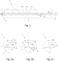
- Figure 1 shows a drilling tool 1 not according to the invention as a twist drill with a substantially cylindrical base body with a drill diameter D, which has a shaft section 2 and a cutting section 3.
- the shaft section 2 is only partially shown.
- the drilling tool 1 rotates in the direction of rotation R with the longitudinal axis L as the axis of rotation.
- the present drilling tool 1 is designed to rotate clockwise.
- the drilling tool 1 has a drill end 4 (also: drill tip), on which main cutting edges are formed.
- Helical flutes 5 are formed along the drilling tool 1. In the present example there are two diametrically opposed flutes 5. Alternatively, flutes 5 can also be arranged asymmetrically. More than two flutes 5 could also be provided.
- the flutes 5 run at a helix angle ⁇ to the longitudinal axis L of the drilling tool 1. Both flutes 5 preferably have the same helix angle.
- the surface of the web 7, which determines a lateral surface of the drilling tool 1, is referred to as the cutting back 8.
- the edge formed by a flute 5 and the web 7 and lying in the direction of rotation R is referred to as the secondary cutting edge 11.
- the cutting section 3 is divided into three subsections: No chip space extension 9 is formed along a section SpErw1 from the drill face 4.
- the length of the first section SpErw1 from the drill face 4 without chip space expansion 9 is preferably greater than or equal to 1 x D, with D drill diameter.
- a chip space expansion 9 begins, which increases along a second projected section SpErw2 in the direction of shaft section 3 and then remains constant along a third projected section SpErw3 in the direction of shaft section 3.
- the length of the first section SpErw1 is 2.5 x D in the present example
- the length of the section SpErw2 is 2.6 x D in the present example.
- Figure 2a shows a cross section of the drilling tool 1 in the area of the first section SpErw1 without chip space expansion 9.
- the shape and depth of the flutes 5 therefore corresponds to the original tool grind in this representation.
- the flute 5 without chip space extension 9 has a slot opening angle of x°, in this example approximately 68°.
- the groove opening angle is the angle between the legs shown as dashed auxiliary lines, which connect a center of the drilling tool 1 and an edge between the flute 5 and cutting backs 8.
- the reference numbers are not repeated in the following figures for the sake of clarity.
- Figure 2b shows a cross section of the drilling tool 1 at a distance SpErw1 from the drill face 4.
- the increase in the groove opening angle is indicated by dashed lines as a measure for the chip space expansion 9 along the distance SpErw2 by the angle y°, in this example 18°.
- the chip space expansion 9 consists of a material removal on the side of a web 7 facing away from the direction of rotation (R), so that a web width b in the area of the chip space expansion 9 is reduced.
- the web is therefore narrower in the area of the chip space extension 9 than in a section of the drilling tool 1 in which no chip space extension 9 is formed.
- the web width b can be determined, for example, by an optical measuring method.
- the edge between the cutting back 8 and the flute 5 in the direction of rotation R forms a secondary cutting edge 11 of the drilling tool 1 and remains unaffected by the chip space expansion 9.
- the chip space extension 9 could capture the webs 7 on both sides of the chip groove. However, it is more beneficial for smooth chip removal if the secondary cutting edge 11 remains untouched by the chip space extension 9. Also visible is a depth t of the flute 5, which remains unchanged in this example.
- Figure 2c shows a cross section of the drilling tool 1 in the area of the third section SpErw3.
- a depth t of the flutes 5 remains unchanged in this example. In other words, a core diameter does not reduce. It can also be provided, in addition to the described lateral expansion of the flutes, to also increase the depth t of the flutes 5.
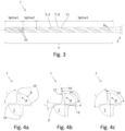
- Figure 3 shows a drilling tool 1 according to an exemplary embodiment.
- the reference numbers correspond Figure 1 .
- guide chamfers 10 are formed on the webs 7 along the route SpErw1. Guide chamfers 10 provide favorable guidance and support for the drilling tool 1 with low friction.
- the guide bevels 10 are realized here by a recess on the cutting back 8, so that per web 7 there is a guide bevel 10 on the secondary cutting edge 11 and a further guide bevel 10 on the side of the web 7 facing away from the direction of rotation R.
- the chip space expansion 9 only begins after the section of the cutting section 3 on which the guide chamfers 10 are formed.
- This has the advantage that the web width b remains unchanged in the area of the guide chamfers 10, whereby favorable support for the drilling tool 1 is achieved.
- the support is provided by the guide bevels 10 over a larger angular range compared to guide bevels 10 on a web 7 with a reduced web width b.
- Figure 4a shows a cross section of the drilling tool 1 in the area of the section SpErw1, on which the guide chamfers 10 are formed. It can be seen that the guide chamfers 10 are formed by a recess on the cutting back 8. The guide chamfers 10 are distributed at angular intervals of approximately 90° along the circumference of the drilling tool 1, whereby uniform support and guidance of the drilling tool 1 is achieved.
- the length of the section SpErw1, on which the guide chamfers 10 are formed is 3.5 x the drill diameter D in the present example.
- FIG 4b shows a section in section SpErw2, in which the chip space extension 9 begins.
- the chip space extension 9 is - as in the previous example - designed in such a way that the web width b on a web 7 on the side facing away from the direction of rotation 7 is reduced. In other words, the secondary cutting edge 11 remains untouched by the chip space extension 9.
- the web 7 is therefore not reduced in its web width b from both sides.
- the web width b decreases along the section SpErw2 from the original value b1 to the value b2. In section SpErw2, no guide chamfers are formed on the webs 7.
- Figure 4c shows a cross section of the drilling tool 1 in the area of the third section SpErw3.
- the web width b has changed compared to the value b1 from the situation in Figure 4a reduced to the value b2.
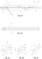
- FIG. 5a shows a drilling tool 1 according to a further exemplary embodiment. Coolant channels 12 running inside the drilling tool 1 are provided here. Guide chamfers 10 are formed in the area of route I4. With regard to the remaining reference numbers, what was said for the previous exemplary embodiments applies.
- a coolant/lubricant can be conveyed to the drill face 4 through the coolant channels 12.
- the coolant channels 12 run twisted at a spiral angle to the longitudinal axis L.
- the function of the inventive drilling tool 1 is particularly advantageously supported by the coolant/lubricant that can be conveyed to the drill end 4 via coolant channels 12, since the coolant/lubricant further promotes the removal of chips.
- a distribution chamber 13 for the coolant/lubricant is provided in the shaft section 2.
- the coolant/lubricant can be advantageously sent from a clamp (not shown) via the distribution chamber 13 Drilling tool 1 is handed over.
- This embodiment with a distribution chamber 13 is particularly interesting for particularly long tools and/or tools with small diameters in order to keep flow resistance for the coolant/lubricant low.
- Figure 5b shows a detail of a drilling tool 1 according to a further exemplary embodiment.
- No distribution chamber 13 is provided in the shaft section 2. Rather, the coolant channels 12 extend over the entire length of the drilling tool 1.
- FIGS 6a to 6c show cross sections of drilling tools 1 with coolant channels 12.
- Figure 6a shows a cross section of the drilling tool 1 in the area of the route I4, along which the guide chamfers 10 are formed.
- the internal coolant channels 12 can be seen in the cross section of the drilling tool 1.
- the coolant channels 12 have a circular cross section.
- Figure 6b shows a section in section SpErw2, in which the chip space extension 9 begins.
- the chip space extension 9 is - as in the previous exemplary embodiments - designed in such a way that the web width b is reduced on a web 7 on the side facing away from the direction of rotation 7. It is advantageous if the coolant channels 12 are arranged in such a way that a sufficient distance from the chip space extension 9 remains in order not to weaken the web 7 in the area of the coolant channels 12.
- Figure 6c shows a cross section of the drilling tool 1 in the area of the third section SpErw3.
- coolant channels 12 The presence of coolant channels 12 is independent of the presence of guide chamfers 10. Drilling tools 1 with coolant channels 12 can therefore exist without guide chamfers 10.
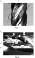
- Figure 7 shows a photographic image of a drilling tool 1 according to the invention. Highlighted is the chip space expansion 9, which is formed at the expense of the webs 7 on the side facing away from the direction of rotation R.
- Marked by arrows are grinding marks which are produced by the intervention of a rotating grinding tool (not shown), in particular a profile grinding wheel.
- the chip space expansion 9 created by the engagement of the grinding tool has a main extension direction
- the chip space extension 9 is preferably produced by engaging the grinding tool in such a way that a plane of rotation of the grinding tool is set at an angle ⁇ to the longitudinal axis L of the drilling tool 1 and then the flute 5 is moved relative to the drilling tool 1, so that webs 7 are on the The side facing away from the direction of rotation R can be partially removed.
- Figure 8 shows a further photographic image of a drilling tool 1 according to the invention. It can be seen that in the area of the chip space extension 9 a web width b2 of the web 7 is reduced compared to an area in the longitudinal direction in front of it with a web width b1.
Landscapes
- Engineering & Computer Science (AREA)
- Mechanical Engineering (AREA)
- Drilling Tools (AREA)
Description
- Die vorliegende Erfindung betrifft ein Bohrwerkzeug mit den Merkmalen des Oberbegriffs von Anspruch 1.
- Gattungsgemäße Bohrwerkzeuge, insbesondere Spiralbohrer, umfassen einen zylindrischen Grundkörper, an welchem wendelförmig Stege und zwischen Stegen Spannuten ausgebildet sind. Der Winkel, in welchem die Spannuten zu einer Mittelachse des Spiralbohrers geneigt verläuft, ist der Drallwinkel (auch als Spiralwinkel bezeichnet) des Spiralbohrers. Der Drallwinkel kann über die Länge des Spiralbohrers veränderlich sein.
- In der Regel weisen Spiralbohrer zwei wendelförmige Spannuten auf.
- Die Spannuten ermöglichen einen Abtransport von Spänen.
- Aus dem Stand der Technik ist es bekannt, die Spannuten eines Bohrwerkzeugs durch Aufschleifen zu vergrößern.
- Eine so geschaffene Spanraumerweiterung schafft zusätzliches Volumen zur Aufnahme und Abtransport von Spänen. Spanraumerweiterung bedeutet allgemein, dass ein freier Querschnitt einer Spannut gegenüber dem eigentlichen Werkzeugschliff vergrößert wird.
- Die
EP1396303A2 (MITSUBISHI MATERIALS CORP - 10.03.2004 ) zeigt ein - Bohrwerkzeug nach dem Oberbegriff des Anspruchs 1 mit verdrallt verlaufenden Spannuten mit zwischen der Spannuten ausgebildeten, teilweise Führungsfasen aufweisenden Stegen mit einer Stegbreite, wobei in wenigstens eine der Spannuten wenigstens abschnittsweise eine Spanraumerweiterung zur Vergrößerung des Spanraums eingebracht ist, wobei die Stegbreite im Bereich der Spanraumerweiterung reduziert ist.
- Die
WO 95/04624 (Kennametal - 16.02.1995 - Die
DE69209034T2 (Sumitomo Electric - 02.10.2002 ) zeigt einen Bohrer mit Spannuten von in Richtung Schaft allmählich zunehmender Breite und allmählich abnehmendem Spiralwinkel. - Die
DE69209034T2 (SANDVIK AB - 25.07. 1996 ) zeigt einen Bohrer, dessen Spannuten von einer ersten, die Späne formenden Zone in eine zweite, die Späne lediglich transportierende Zone mit einer größeren Breite oder einem größeren Querschnitt übergehen. - Aufgabe der vorliegenden Erfindung ist es, ein verbessertes Bohrwerkzeug anzugeben.
- Die Aufgabe wird erfüllt durch ein Bohrwerkzeug mit den Merkmalen von Anspruch 1. Bevorzugte Weiterbildungen sind in den abhängigen Ansprüchen angegeben.
- Das erfindungsgemäße Bohrwerkzeug ist so ausgebildet, dass zumindest über einen Teil des Schneidenabschnitts Führungsfasen ausgebildet sind und die Spanraumerweiterung, von der Bohrerstirn in Richtung Schaftabschnitt betrachtet, erst nach dem Bereich des Schneidenabschnitts einsetzt, an dem Führungsfasen ausgebildet sind. Es ist ferner vorgesehen, dass die Spanraumerweiterung einen Steg erfasst, sodass eine Stegbreite im Bereich der Spanraumerweiterung reduziert ist. In anderen Worten wird der Spanraum des Werkzeugs auf Kosten des Steges vergrößert. Der Steg ist also im Bereich der Spanraumerweiterung schmäler als in einem Abschnitt des Bohrwerkzeugs, in dem keine Spanraumerweiterung ausgebildet ist.
- Spanraumerweiterungen aus dem Stand der Technik sind unter anderem als lokale Vertiefungen von Spannuten an deren Grund ausgebildet. Die Schaffung zusätzlichen Spanraums durch bekannte Spanraumerweiterungen ist in diesen Fällen dadurch limitiert, als der tragende Querschnitt des Bohrwerkzeugs, also der Kerndurchmesser, geschwächt wird.
- Eine erfindungsgemäße Spanraumerweiterung erweitert eine Spannut hingegen lateral, indem eine Stegbreite reduziert wird. Zusätzlich kann natürlich auch weiterer Spanraum durch Vertiefung der Spannut an deren Grund erzeugt werden.
- Die erfindungsgemäße Spanraumerweiterung begünstigt einen Abtransport von Spänen. Eine Verstopfungsneigung wird reduziert.
- Bevorzugt sind Spanraumerweiterungen an allen Spannuten des Bohrwerkzeugs ausgebildet. Es kann natürlich auch vorgesehen sein, eine Spanraumerweiterung nur an einer Spannut auszubilden. Für eine gleichmäßige mechanische Belastung des Bohrwerkzeugs ist es aber günstiger, Spanraumerweiterungen an allen Spannuten vorzusehen.
- Durch die Formänderung der Spannut durch die erfindungsgemäße Spanraumerweiterung erfahren die Späne eine Beschleunigung, was einen Spanbruch begünstigt.
- Beschleunigung ist so zu verstehen, dass die Späne eine Impulsänderung erfahren. Die Impulsänderung tritt durch die erfindungsgemäße Ausgestaltung der Spanraumerweiterung vorwiegend als Veränderung der Bewegungsrichtung der Späne, also durch eine Spanumlenkung auf.
- Ein Steg weist auf der in Drehrichtung liegenden Seite eine Nebenschneide auf. Die Verringerung der Stegbreite erfolgt bevorzugt auf der der Nebenschneide abgewandten Seite des Steges, damit die Form der Nebenschneide von der Spanraumerweiterung unbeeinflusst bleibt. Auf diese Weise ist ein sanfter Spanablauf gegeben.
- In anderen Worten ist die gemäß dieser Weiterbildung die Spanraumerweiterung so ausgebildet, dass nur die einer Drehrichtung abgewandte Seite eines Steges von der Spanraumerweiterung erfasst ist.
- Neben der erwähnten Spanumlenkung besteht ein weiterer Vorteil der Erfindung auch darin, dass eine deutliche Vergrößerung des Spanvolumens innerhalb eines kurzen Wegs geschaffen werden kann. Mit kurzem Weg ist gemeint, dass die Spanraumerweiterung entlang eines kleinen Winkelbereichs - bezogen auf einen Verlauf der wendelförmigen Spannuten - oder anders ausgedrückt, innerhalb einer kurzen Strecke - bezogen auf eine Längserstreckung des Bohrwerkzeugs - realisiert werden kann.
- Besonders interessant ist das für Mikrobohrer, da hier die Spanräume entsprechend klein und kurz sind.
- Bevorzugt vergrößert sich durch die Spanraumerweiterung ein Nutöffnungswinkel einer Spannut. Unter Nutöffnungswinkel wird im Rahmen dieser Anmeldung jener Winkel verstanden, den die gegenüberliegenden Flanken einer Spannut miteinander einschließen.
- Bevorzugt ist vorgesehen, dass die Spanraumerweiterung, von der Bohrerstirn in Richtung Schaftabschnitt betrachtet, erst bei einem Abstand von der Bohrerstirn einsetzt. In anderen Worten kann also vorgesehen sein, dass der vordere Teil des Schneidenabschnitts keine Spanraumerweiterung aufweist. Bevorzugt beginnt die Spanraumerweiterung erst bei einem Abstand von der Bohrerstirn von größer oder gleich 1 x D, mit D ist der Bohrerdurchmesser. Der Vorteil dieser Weiterbildung ist, dass im besagten Teil des Schneidenabschnitts ohne Spanraumerweiterung die volle Stegbreite erhalten ist und das Bohrwerkzeug dadurch im Spanbildungsbereich robuster ist. Es hat sich gezeigt, dass der Abschnitt ohne Spanraumerweiterung nicht zu lang sein soll, da sonst die günstigen Effekte der daran anschließenden Spanraumerweiterung nicht zur vollen Entfaltung kommen. Als Richtwert konnte festgestellt werden, dass die Spanraumerweiterung höchstens bei einem Abstand von der Bohrerstirn von 8 x D einsetzen soll, da ansonsten die Späne zu lang werden.
- Insbesondere bevorzugt sind Führungsfasen, von der Bohrerstirn in Richtung Schaftabschnitt betrachtet, bis zu einem Abstand von der Bohrerstirn von kleiner oder gleich 3 x D ausgebildet.
- Insbesondere bevorzugt sind an einem Steg zwei Führungsfasen ausgebildet. Erfindungsgemäß ist vorgesehen, dass die Spanraumerweiterung, von der Bohrerstirn in Richtung Schaftabschnitt betrachtet, erst nach dem Bereich des Schneidenabschnitts einsetzen, an dem Führungsfasen ausgebildet sind. Dies hat den Vorteil, dass die Stege im Bereich der Führungsfasen ihre ursprüngliche Breite aufweisen, was günstig für eine Führung bzw. Abstützung des Bohrers ist.
- Bevorzugt ist vorgesehen, dass die von der Spanraumerweiterung erzielte Erweiterung des Spanraums entlang der Bohrerlängsachse zunimmt.
- Die Spanraumerweiterung muss also nicht konstant sein, sondern kann entlang der Bohrerlängsachse zunehmen. Aus mechanischen Gründen günstig ist es, wenn die Spanraumerweiterung kontinuierlich, also nicht sprunghaft zunimmt.
- Bevorzugt ist vorgesehen, dass wobei die Zunahme der Spanraumerweiterung, bezogen auf einen Verlauf der Spannuten, innerhalb von kleiner oder gleich 360° erfolgt. Dies beschreibt die bereits erwähnte Ausprägung, dass die Spanraumerweiterung innerhalb eines kurzen Weges das gewünschte Maß erreicht. Bei 360° würde also innerhalb einer Umdrehung einer wendelförmigen Spannut die Spanraumerweiterung von einem Startwert auf das gewünschte Endmaß anwachsen.
- Bezogen auf die Bohrerlängsachse kann die Vergrößerung der Spanraumerweiterung beispielsweise entlang einer projizierten Strecke von kleiner oder gleich 2,5 x dem Bohrerdurchmesser D erfolgen.
- Bevorzugt ist vorgesehen, dass die Spanraumerweiterung entlang einer ersten projizierten Strecke in Richtung Schaftabschnitt zunimmt, um danach entlang einer zweiten projizierten Strecke in Richtung Schaftabschnitt konstant zu bleiben.
- Bevorzugt ist die Spanraumerweiterung als Einschliff ausgebildet. Das heißt, die Spanraumerweiterung ist bevorzugt durch Schleifen eingebracht. Alternativ könnte Material durch andere Verfahren, wie etwa Laserablation, abgetragen werden.
- Bevorzugt ist vorgesehen, dass die Spannut im Bereich der Spanraumerweiterung eine veränderliche Tiefe aufweist. Mit Tiefe ist ein Abstand von einer Mantelfläche des Bohrwerkzeugs zum Grund der Spannut gemeint. Bevorzugt kann die Tiefe in Richtung Schaftabschnitt zunehmen. Damit wird auch zum Ausdruck gebracht, dass die Tiefe und die laterale Abmessung der Spanraumerweiterung unabhängig voneinander variierbar sind.
- Bevorzugt ist vorgesehen, dass wenigstens ein im Inneren des Bohrwerkzeugs verlaufender Kühlmittelkanal ausbildet ist. Über einen Kühlmittelkanal kann ein Kühl- / Schmiermittel an die Bohrerstirn gefördert werden. Damit wird die Funktion des Bohrwerkzeugs besonders vorteilhaft unterstützt, da das Kühl- / Schmiermittel einen Abtransport von Spänen bei verringerter Reibung weiter begünstigt. Somit wirken die Maßnahmen besonders vorteilhaft miteinander.
- Bevorzugt ist das Bohrwerkzeug aus einem Verbundwerkstoff umfassend wenigstens einen Hartstoff und wenigstens eine Binderphase ausgebildet. Insbesondere ist das Bohrwerkzeug aus Hartmetall gefertigt. Unter Hartmetall wird vorliegend ein Verbundwerkstoff verstanden, bei dem harte Teilchen, die insbesondere durch Karbide, Karbonitride und/oder Oxokarbonitride der Elemente der Gruppen IVb bis Vlb des Periodensystems der Elemente gebildet sein können, in einer duktilen metallischen Matrix eingebettet sind, die insbesondere aus Co, Ni, Fe oder einer Legierung von diesen gebildet sein kann. In den meisten Fällen sind die harten Teilchen dabei zumindest überwiegend durch Wolframkarbid gebildet und die metallische Matrix besteht im Wesentlichen aus Kobalt.
- Schutz wird auch begehrt für ein Verfahren nach Anspruch 13 zur Herstellung eines Bohrwerkzeugs nach Anspruch 1. Dazu ist vorgesehen, dass ein rotierendes Schleifwerkzeug zu Schaffung einer Spanraumerweiterung entlang der Spannuten bewegt wird, wobei eine Rotationsebene des Schleifwerkzeugs in einem Winkel zur Bohrerlängsachse geneigt ist, welcher Winkel größer ist als der Drallwinkel der entsprechenden Spannut. Das Schleifwerkzeug wird dabei so geführt, dass ein Materialabtrag an jenen Seiten der Stege erfolgt, die bezüglich einer Drehrichtung hinten liegen.
- Die Erfindung wird anhand der Figuren näher erläutert. Darin zeigt:
- Fig. 1
- ein nicht-erfindungsgemäßes Beispiel
- Fig. 2a-c
- Querschnitte des Bohrwerkzeugs von
Figur 1 an verschiedenen Stellen entlang der Längsachse - Fig. 3
- ein Bohrwerkzeug in einem Ausführungsbeispiel
- Fig. 4a-c
- Querschnitte des Bohrwerkzeugs von
Figur 3 an verschiedenen Stellen entlang der Längsachse - Fig. 5a, 5b
- Bohrwerkzeuge in weiteren Ausführungsbeispielen
- Fig. 6a-c
- Querschnitte des Bohrwerkzeugs von
Figur 5 an verschiedenen Stellen entlang der Längsachse - Fig. 7, 8
- fotografische Aufnahmen eines erfindungsgemäßen Bohrwerkzeugs
-
Figur 1 zeigt ein nicht-erfindungsgemäßes Bohrwerkzeug 1 als Spiralbohrer mit einem im Wesentlichen zylindrischen Grundkörper mit einem Bohrerdurchmesser D, der einen Schaftabschnitt 2 und einen Schneidenabschnitt 3 aufweist. Der Schaftabschnitt 2 ist nur ansatzweise dargestellt. In einem Einsatz rotiert das Bohrwerkzeug 1 in Drehrichtung R mit der Längsachse L als Rotationsachse. Das vorliegende Bohrwerkzeug 1 ist also rechtsdrehend ausgeführt. - Das Bohrwerkzeug 1 weist eine Bohrerstirn 4 (auch: Bohrerspitze) auf, an welcher Hauptschneiden ausgebildet sind.
- Entlang des Bohrwerkzeugs 1 sind wendelförmig verlaufende Spannuten 5 eingeformt. Im vorliegenden Beispiel sind es zwei sich diametral gegenüberliegende Spannuten 5. Alternativ können Spannuten 5 auch asymmetrisch angeordnet sein. Es könnten auch mehr als zwei Spannuten 5 vorgesehen sein.
- Die Spannuten 5 verlaufen in einem Drallwinkel β zur Längsachse L des Bohrwerkzeugs 1. Bevorzugt weisen beide Spannuten 5 den gleichen Drallwinkel auf.
- Zwischen den Spannuten 5 besteht ein Steg 7. Die Oberfläche des Stegs 7, welche eine Mantelfläche des Bohrwerkzeugs 1 bestimmt, wird als Schneidrücken 8 bezeichnet.
- Die von einer Spannut 5 und dem Steg 7 gebildete, in Drehrichtung R liegende Kante wird als Nebenschneide 11 bezeichnet.
- Der Schneidenabschnitt 3 ist zur Erläuterung in drei Unterabschnitte eingeteilt: Entlang einer Strecke SpErw1 von der Bohrerstirn 4 ist keine Spanraumerweiterung 9 ausgebildet. Die Länge der ersten Strecke SpErw1 von der Bohrerstirn 4 ohne Spanraumerweiterung 9 ist bevorzugt größer gleich 1 x D, mit D Bohrerdurchmesser.
- Nach der ersten Strecke SpErw1 beginnt eine Spanraumerweiterung 9, die entlang einer zweiten projizierten Strecke SpErw2 in Richtung Schaftabschnitt 3 zunimmt, um danach entlang einer dritten projizierten Strecke SpErw3 in Richtung Schaftabschnitt 3 konstant zu bleiben. Die Länge ersten Strecke SpErw1 beträgt im vorliegenden Beispiel 2,5 x D, die Länge der Strecke SpErw2 beträgt im vorliegenden Beispiel 2,6 x D.
- In den
Figuren 2a bis 2c darunter sind die zu den drei Unterabschnitten korrespondierenden Querschnitte des Bohrwerkzeugs 1 dargestellt. -
Figur 2a zeigt einen Querschnitt des Bohrwerkzeugs 1 im Bereich der ersten Strecke SpErw1 ohne Spanraumerweiterung 9. Die Form und Tiefe der Spannuten 5 entspricht daher in dieser Darstellung dem ursprünglichen Werkzeugschliff. - Die Spannut 5 ohne Spanraumerweiterung 9 weist einen Nutöffnungswinkel von x°, in diesem Beispiel etwa 68° auf. Als Nutöffnungswinkel wird der Winkel zwischen den als strichlierte Hilfslinien eingezeichneten Schenkeln bezeichnet, welche ein Zentrum des Bohrwerkzeugs 1 und eine Kante zwischen der Spannut 5 und Schneidrücken 8 verbinden. Die Bezugszeichen sind in den nachfolgenden Figuren der Übersichtlichkeit halber nicht wiederholt.
-
Figur 2b zeigt einen Querschnitt des Bohrwerkzeugs 1 in einem Abstand SpErw1 von der Bohrerstirn 4. Strichliert angedeutet ist die Vergrößerung des Nutöffnungswinkels als Maß für die Spanraumerweiterung 9 entlang der Strecke SpErw2 um den Winkel y°, in diesem Beispiel 18°. Entlang der Strecke SpErw2 vergrößert sich der Spanraum der Spannut 5, ausgedrückt über den Nutöffnungswinkel, von einem Startwert von hier x° kontinuierlich, um am Ende der Strecke SpErw2 x° + y° = z° zu betragen. - Die Spanraumerweiterung 9 besteht in einer Materialabnahme an der der Drehrichtung (R) abgewandten Seite eines Steges 7, sodass eine Stegbreite b im Bereich der Spanraumerweiterung 9 reduziert ist. Der Steg ist also im Bereich der Spanraumerweiterung 9 schmäler als in einem Abschnitt des Bohrwerkzeugs 1, in dem keine Spanraumerweiterung 9 eingeformt ist.
- Die Stegbreite b kann beispielsweise durch ein optisches Messverfahren ermittelt werden.
- Die Kante zwischen dem Schneidrücken 8 und der Spannut 5 in Drehrichtung R trägt bildet eine Nebenschneide 11 des Bohrwerkzeugs 1 und bleibt von der Spanraumerweiterung 9 unbeeinflusst.
- Alternativ könnte die Spanraumerweiterung 9 die Stege 7 auf beiden Seiten der Spannut erfassen. Allerdings ist es für einen sanften Spanablauf günstiger, wenn die Nebenschneide 11 von der Spanraumerweiterung 9 unberührt bleibt. Weiters ersichtlich ist eine Tiefe t der Spannut 5, die in diesem Beispiel unverändert bleibt.
-
Figur 2c zeigt einen Querschnitt des Bohrwerkzeugs 1 im Bereich des dritten Abschnittes SpErw3. Hier beträgt der Nutöffnungswinkel konstant z° mit z = 86°. - Man erkennt weiters, dass die Spanraumerweiterung 9 auf Kosten der Stege 7 auf der der Drehrichtung R abgewandten Seite erfolgt. Die Stegbreite b hat sich gegenüber dem Wert b1 von der Situation in
Figur 2a auf den Wert b2 reduziert. - Eine Tiefe t der Spannuten 5 bleibt in diesem Beispiel unverändert. In anderen Worten reduziert sich ein Kerndurchmesser nicht. Es kann auch vorgesehen sein, zusätzlich zur beschriebenen lateralen Erweiterung der Spannuten auch noch die Tiefe t der Spannuten 5 zu vergrößern.
-
Figur 3 zeigt ein Bohrwerkzeug 1 nach einem Ausführungsbeispiel. Die Bezugszeichen entsprechenFigur 1 . Im Unterschied zum Beispiel nachFigur 1 sind hier entlang der Strecke SpErw1 an den Stegen 7 Führungsfasen 10 ausgebildet. Führungsfasen 10 bewirken eine günstige Führung und Abstützung des Bohrwerkzeugs 1 bei geringer Reibung. - Die Führungsfasen 10 sind hier durch eine Ausnehmung am Schneidrücken 8 realisiert, sodass pro Steg 7 eine Führungsfase 10 an der Nebenschneide 11 und eine weitere Führungsfase 10 an der bezüglich der Drehrichtung R abgewandten Seite des Steges 7 vorliegt.
- In diesem Ausführungsbeispiel setzt die Spanraumerweiterung 9 erst nach dem Abschnitt des Schneidenabschnitts 3 ein, an welchem die Führungsfasen 10 ausgebildet sind. Dies hat den Vorteil, dass die Stegbreite b im Bereich der Führungsfasen 10 unverändert breit ist, wodurch eine günstige Abstützung des Bohrwerkzeugs 1 erzielt wird. So erfolgt die Abstützung durch die Führungsfasen 10 über einen größeren Winkelbereich im Vergleich zu Führungsfasen 10 an einem Steg 7 mit verringerter Stegbreite b.
- Aus
Figur 4a gehen die Verhältnisse noch deutlicher hervor.Figur 4a zeigt einen Querschnitt des Bohrwerkzeugs 1 im Bereich der Strecke SpErw1, an der die Führungsfasen 10 ausgebildet sind. Man erkennt, dass die Führungsfasen 10 durch eine Ausnehmung am Schneidrücken 8 gebildet sind. Die Führungsfasen 10 sind in Winkelabständen von etwa 90° entlang des Umfangs des Bohrwerkzeugs 1 verteilt, wodurch eine gleichmäßige Abstützung und Führung des Bohrwerkzeugs 1 erreicht wird. - Die Länge der Strecke SpErw1, an der die Führungsfasen 10 ausgebildet sind, beträgt im vorliegen Beispiel 3,5 x dem Bohrerdurchmesser D.
-
Figur 4b zeigt einen Schnitt im Abschnitt SpErw2, in welchem die Spanraumerweiterung 9 einsetzt. Die Spanraumerweiterung 9 ist - wie auch im vorherigen Beispiel - so ausgeführt, dass die Stegbreite b an einem Steg 7 auf der in Drehrichtung 7 abgewandten Seite reduziert wird. In anderen Worten bleibt die Nebenschneide 11 von der Spanraumerweiterung 9 unberührt. Der Steg 7 wird also nicht von beiden Seiten in seiner Stegbreite b reduziert. Die Stegbreite b verringert sich entlang des Abschnitts SpErw2 vom ursprünglichen Wert b1 auf den Wert b2. Im Abschnitt SpErw2 sind keine Führungsfasen an den Stegen 7 ausgebildet. -
Figur 4c zeigt einen Querschnitt des Bohrwerkzeugs 1 im Bereich des dritten Abschnittes SpErw3. Die Stegbreite b hat sich gegenüber dem Wert b1 von der Situation inFigur 4a auf den Wert b2 reduziert. - Für die Nutöffnungswinkel gilt das anhand der
Figuren 2a-c diskutierte. -
Figur 5a zeigt ein Bohrwerkzeug 1 nach einem weiteren Ausführungsbeispiel. Hier sind im Inneren des Bohrwerkzeug 1 verlaufende Kühlmittelkanäle 12 vorgesehen. Im Bereich der Strecke I4 sind Führungsfasen 10 ausgebildet. Bezüglich der übrigen Bezugszeichen gilt das für die vorherigen Ausführungsbeispiele gesagte. - Durch die Kühlmittelkanäle 12 kann ein Kühl- / Schmiermittel an die Bohrerstirn 4 gefördert werden. Die Kühlmittelkanäle 12 verlaufen verdrallt in einem Spiralwinkel zur Längsachse L.
- Durch das über Kühlmittelkanäle 12 an die Bohrerstirn 4 förderbare Kühl- / Schmiermittel wird die Funktion des erfinderischen Bohrwerkzeugs 1 besonders vorteilhaft unterstützt, da das Kühl- / Schmiermittel einen Abtransport von Spänen weiter begünstigt.
- Ferner ist im Schaftabschnitt 2 eine Verteilerkammer 13 für das Kühl- / Schmiermittel vorgesehen. Über die Verteilerkammer 13 kann das Kühl- / Schmiermittel von einer Einspannung (nicht gezeigt) vorteilhaft an das Bohrwerkzeug 1 übergeben werden. Diese Ausführungsform mit einer Verteilerkammer 13 ist insbesondere für besonders lange Werkzeuge und / oder Werkzeuge mit geringen Durchmessern interessant, um einen Strömungswiderstand für das Kühl- / Schmiermittel gering zu halten.
-
Figur 5b zeigt ein Detail eines Bohrwerkzeug 1 nach einem weiteren Ausführungsbeispiel. Hier ist im Unterschied zu dem Ausführungsbeispiel vonFigur 5a im Schaftabschnitt 2 keine Verteilerkammer 13 vorgesehen. Vielmehr erstrecken sich die Kühlmittelkanäle 12 über die gesamte Länge des Bohrwerkzeugs 1. -
Figuren 6a bis 6c zeigen Querschnitte von Bohrwerkzeugen 1 mit Kühlmittelkanälen 12. -
Figur 6a zeigt einen Querschnitt des Bohrwerkzeugs 1 im Bereich der Strecke I4, entlang welcher die Führungsfasen 10 ausgebildet sind. Im Querschnitt des Bohrwerkzeugs 1 sind die innenliegenden Kühlmittelkanäle 12 zu erkennen. Die Kühlmittelkanäle 12 weisen in diesem Beispiel einen kreisförmigen Querschnitt auf. -
Figur 6b zeigt einen Schnitt im Abschnitt SpErw2, in welchem die Spanraumerweiterung 9 einsetzt. Die Spanraumerweiterung 9 ist - wie auch in den vorherigen Ausführungsbeispielen - so ausgeführt, dass die Stegbreite b an einem Steg 7 auf der in Drehrichtung 7 abgewandten Seite reduziert wird. Günstig ist es, wenn die Kühlmittelkanäle 12 so angeordnet sind, dass ein ausreichender Abstand zur Spanraumerweiterung 9 bestehen bleibt, um den Steg 7 im Bereich der Kühlmittelkanäle 12 nicht zu schwächen. -
Figur 6c zeigt einen Querschnitt des Bohrwerkzeugs 1 im Bereich des dritten Abschnittes SpErw3. - Das Vorhandensein von Kühlmittelkanälen 12 ist unabhängig von einem Vorhandensein von Führungsfasen 10. Es können also Bohrwerkzeuge 1 mit Kühlmittelkanälen 12 ohne Führungsfasen 10 bestehen.
-
Figur 7 zeigt eine fotografische Aufnahme eines erfindungsgemäßen Bohrwerkzeugs 1. Hervorgehoben ist die Spanraumerweiterung 9, die auf Kosten der Stege 7 auf der der Drehrichtung R abgewandten Seite ausgebildet ist. - Durch Pfeile kenntlich gemacht sind Schleifriefen, welche durch einen Eingriff eines rotierenden Schleifwerkzeugs (nicht gezeigt), insbesondere einer Profilschleifscheibe erzeugt sind. Die durch den Eingriff des Schleifwerkzeugs erzeugte Spanraumerweiterung 9 weist eine Haupterstreckungsrichtung X auf, die in einem Winkel γ zur Bohrerlängsachse L verläuft, wobei der Winkel γ größer ist als der Drallwinkel β der entsprechenden Spannut 5.
- Die Herstellung der Spanraumerweiterung 9 erfolgt bevorzugt durch einen Eingriff des Schleifwerkzeugs derart, dass eine Rotationsebene des Schleifwerkzeugs in einem Winkel γ zur Längsachse L des Bohrwerkzeugs 1 angestellt wird und dann der Spannut 5 folgend gegenüber dem Bohrwerkzeug 1 bewegt wird, sodass Stege 7 auf der der Drehrichtung R abgewandten Seite teilweise abgetragen werden.
-
Figur 8 zeigt eine weitere fotografische Aufnahme eines erfindungsgemäßen Bohrwerkzeugs 1. Zu erkennen ist, dass im Bereich der Spanraumerweiterung 9 eine Stegbreite b2 des Stegs 7 reduziert ist gegenüber einem Bereich in Längsrichtung davor mit einer Stegbreite b1. -
- 1
- Bohrwerkzeug
- 2
- Schaftabschnitt
- 3
- Schneidenabschnitt
- 4
- Bohrerstirn
- 5
- Spannut
- 6
- Spanraum
- 7
- Steg
- 8
- Schneidrücken
- 9
- Spanraumerweiterung
- 10
- Führungsfase
- 11
- Nebenschneide
- 12
- Kühlmittelkanal
- 13
- Verteilerkammer
- D
- Bohrerdurchmesser
- L
- Längsachse
- R
- Drehrichtung
- b
- Stegbreite
- t
- Tiefe der Spanraumerweiterung
- β
- Drallwinkel
- γ
- Winkel der Haupterstreckungsrichtung der Spanraumerweiterung
Claims (13)
- Bohrwerkzeug (1), insbesondere Spiralbohrer, mit einem im Wesentlichen zylindrischen Grundkörper, umfassend einen Schaftabschnitt (2), einen Schneidenabschnitt (3) mit einem Bohrerdurchmesser (D),eine Bohrerstirn (4), eine Bohrerlängsachse (L) um welche das Bohrwerkzeug in einer Drehrichtung (R) drehbar ist,wenigstens zwei entlang der Bohrerlängsachse (L) in wenigstens einem Drallwinkel (β) geneigte, verdrallt verlaufende Spannuten (5), welche Spannuten (5) einen Spanraum (6) bilden, zwischen den Spannuten (5) ausgebildete Stege (7) mit einer Stegbreite (b), wobei in wenigstens eine der Spannuten (5) wenigstens abschnittsweise eine Spanraumerweiterung (9) zur Vergrößerung des Spanraums (6) eingebracht ist, wobei die Stegbreite (b) im Bereich der Spanraumerweiterung (9) reduziert ist, wobei zumindest über einen Teil des Schneidenabschnitts (3) Führungsfasen (10) ausgebildet sind, dadurch gekennzeichnet, dass die Spanraumerweiterung (9), von der Bohrerstirn (4) in Richtung Schaftabschnitt (2) betrachtet, erst nach dem Bereich des Schneidenabschnitts (3) einsetzt, an dem Führungsfasen (10) ausgebildet sind.
- Bohrwerkzeug (1) nach Anspruch 1, wobei die Spanraumerweiterung (9) so ausgebildet ist, dass nur eine der Drehrichtung (R) abgewandte Seite eines Steges (7) von der Spanraumerweiterung (9) erfasst ist.
- Bohrwerkzeug (1) nach Anspruch 1 oder 2, wobei sich durch die Spanraumerweiterung (9) ein Nutöffnungswinkel einer Spannut vergrößert.
- Bohrwerkzeug (1) nach einem der vorangegangenen Ansprüche, wobei die Spanraumerweiterung (9), von der Bohrerstirn (4) in Richtung Schaftabschnitt (3) betrachtet, erst bei einem Abstand einer ersten projizierten Strecke (SpErw1) von der Bohrerstirn (4) von größer oder gleich 1 x Bohrerdurchmesser (D) einsetzt.
- Bohrwerkzeug (1) nach einem der vorangegangenen Ansprüche, wobei die von der Spanraumerweiterung (9) erzielte Erweiterung des Spanraums (6) entlang der Bohrerlängsachse (L) zunimmt.
- Bohrwerkzeug (1) nach Anspruch 5, wobei die Vergrößerung der Spanraumerweiterung (9), bezogen auf einen Verlauf der Spannuten (5), innerhalb von kleiner oder gleich 360° erfolgt.
- Bohrwerkzeug (1) nach Anspruch 5 oder 6, wobei die die Vergrößerung der Spanraumerweiterung (9), bezogen auf die Bohrerlängsachse (L) entlang einer projizierten Strecke von kleiner oder gleich 2,5 x dem Bohrerdurchmesser (D) erfolgt.
- Bohrwerkzeug (1) nach einem der vorangegangenen Ansprüche, wobei die Spanraumerweiterung (9) entlang einer zweiten projizierten Strecke (SpErw2) in Richtung Schaftabschnitt (3) zunimmt, um danach entlang einer dritten projizierten Strecke (SpErw3) in Richtung Schaftabschnitt (3) konstant zu bleiben.
- Bohrwerkzeug (1) nach einem der vorangegangenen Ansprüche, wobei die Spanraumerweiterung (9) als Einschliff ausgebildet ist.
- Bohrwerkzeug (1) nach einem der vorangegangenen Ansprüche, wobei eine Spannut (5) im Bereich der Spanraumerweiterung (9) eine veränderliche Tiefe (t) aufweist
- Bohrwerkzeug (1) nach einem der vorangegangenen Ansprüche, wobei wenigstens ein im Inneren des Bohrwerkzeugs (1) verlaufender Kühlmittelkanal (12) ausbildet ist.
- Bohrwerkzeug (1) nach einem der vorangegangenen Ansprüche, wobei das Bohrwerkzeug (1) aus Hartmetall ausbildet ist.
- Verfahren zur Herstellung eines Bohrwerkzeugs (1) nach Anspruch 1, wobei ein rotierendes Schleifwerkzeug zur Schaffung einer Spanraumerweiterung (9) entlang von Spannuten (5) bewegt wird, dadurch gekennzeichnet, dass eine Rotationsebene des Schleifwerkzeugs in einem Winkel (γ) zur Längsachse (L) des Bohrwerkzeugs (1) geneigt ist, welcher Winkel (γ) größer ist als der Drallwinkel (β) der entsprechenden Spannut (5) und dass das Schleifwerkzeug so geführt wird, dass eine Stegbreite (b) im Bereich der Spanraumerweiterung (9) reduziert wird.
Priority Applications (6)
| Application Number | Priority Date | Filing Date | Title |
|---|---|---|---|
| EP18212364.6A EP3666433B1 (de) | 2018-12-13 | 2018-12-13 | Bohrwerkzeug |
| JP2021533210A JP2022512198A (ja) | 2018-12-13 | 2019-11-27 | 穴あけ工具 |
| CN201980079646.4A CN113165088B (zh) | 2018-12-13 | 2019-11-27 | 钻具 |
| PCT/EP2019/082747 WO2020120138A1 (de) | 2018-12-13 | 2019-11-27 | Bohrwerkzeug |
| US17/413,644 US12076796B2 (en) | 2018-12-13 | 2019-11-27 | Drilling tool |
| KR1020217015147A KR102708822B1 (ko) | 2018-12-13 | 2019-11-27 | 드릴링 공구 |
Applications Claiming Priority (1)
| Application Number | Priority Date | Filing Date | Title |
|---|---|---|---|
| EP18212364.6A EP3666433B1 (de) | 2018-12-13 | 2018-12-13 | Bohrwerkzeug |
Publications (3)
| Publication Number | Publication Date |
|---|---|
| EP3666433A1 EP3666433A1 (de) | 2020-06-17 |
| EP3666433B1 true EP3666433B1 (de) | 2023-09-27 |
| EP3666433C0 EP3666433C0 (de) | 2023-09-27 |
Family
ID=64665452
Family Applications (1)
| Application Number | Title | Priority Date | Filing Date |
|---|---|---|---|
| EP18212364.6A Active EP3666433B1 (de) | 2018-12-13 | 2018-12-13 | Bohrwerkzeug |
Country Status (6)
| Country | Link |
|---|---|
| US (1) | US12076796B2 (de) |
| EP (1) | EP3666433B1 (de) |
| JP (1) | JP2022512198A (de) |
| KR (1) | KR102708822B1 (de) |
| CN (1) | CN113165088B (de) |
| WO (1) | WO2020120138A1 (de) |
Family Cites Families (22)
| Publication number | Priority date | Publication date | Assignee | Title |
|---|---|---|---|---|
| SE502255C2 (sv) * | 1991-12-16 | 1995-09-25 | Sandvik Ab | Borr med spånkanaler, innefattande en första och en andra spånmatande zon, med olika tvärsnitt |
| US5350261A (en) * | 1992-03-12 | 1994-09-27 | Mitsubishi Materials Corporation | Twist drill |
| CA2168889C (en) * | 1993-08-06 | 2003-12-09 | Kennametal Hertel Ag Werkzeuge + Hartstoffe | Twist drill |
| JPH09277108A (ja) | 1996-02-14 | 1997-10-28 | Sumitomo Electric Ind Ltd | ドリル |
| KR100485987B1 (ko) * | 1996-02-29 | 2005-08-03 | 코메트 그룹 홀딩 게엠베하 | 기계공구용드릴공구및상기드릴공구를제작하는방법 |
| US6315504B1 (en) * | 1998-10-27 | 2001-11-13 | Nachi-Fujikoshi Corporation | Twist Drill |
| US7306411B2 (en) * | 2002-09-03 | 2007-12-11 | Mitsubishi Materials Corporation | Drill with groove width variation along the drill and double margin with a thinning section at the tip |
| JP2004090196A (ja) | 2002-09-03 | 2004-03-25 | Mitsubishi Materials Corp | ドリルおよびその製造方法 |
| JP3720010B2 (ja) * | 2002-10-02 | 2005-11-24 | オーエスジー株式会社 | 深穴加工用ドリル |
| EP1512476B1 (de) * | 2003-09-08 | 2013-10-09 | Black & Decker Inc. | Selbstzentrierendes Bohrwerkzeug mit Pilotschneidteil |
| JP2006326752A (ja) | 2005-05-26 | 2006-12-07 | Mitsubishi Materials Corp | ドリル |
| SE531188C2 (sv) * | 2007-05-29 | 2009-01-13 | Sandvik Intellectual Property | Borrkropp för spånavskiljande bearbetning |
| DE102008023856A1 (de) * | 2008-05-16 | 2009-11-19 | Gühring Ohg | Mehrschneidiges Vollhartmetall-Bohrwerkzeug |
| DE102008027705B4 (de) * | 2008-06-11 | 2024-06-13 | Gühring KG | Mehrschneidiges Bohrwerkzeug zur Zerspanung von schwer zerspanbaren, insbesondere langspanenden Werkstoffen |
| DE102009025223A1 (de) * | 2009-06-08 | 2010-12-09 | MAPAL Fabrik für Präzisionswerkzeuge Dr. Kress KG | Bohrer |
| DE102010017163A1 (de) * | 2010-05-31 | 2011-12-01 | Gühring Ohg | Bohrwerkzeug |
| JP5368384B2 (ja) * | 2010-06-30 | 2013-12-18 | オーエスジー株式会社 | 深穴加工用ドリル |
| CA2817079C (en) * | 2010-11-26 | 2019-01-08 | Cpl Holdings Pty Ltd | Orthopaedic drill bit |
| IL211236A0 (en) * | 2011-02-15 | 2011-04-28 | Vladimir Volokh | Rotary cutter |
| DE102012012479A1 (de) * | 2012-03-26 | 2013-09-26 | MAPAL Fabrik für Präzisionswerkzeuge Dr. Kress KG | Bohrer |
| JP6252717B1 (ja) * | 2016-04-15 | 2017-12-27 | 三菱日立ツール株式会社 | 小径ドリル |
| JP6690456B2 (ja) * | 2016-07-29 | 2020-04-28 | 三菱マテリアル株式会社 | 刃先交換式ドリルのドリル本体、及び刃先交換式ドリル |
-
2018
- 2018-12-13 EP EP18212364.6A patent/EP3666433B1/de active Active
-
2019
- 2019-11-27 KR KR1020217015147A patent/KR102708822B1/ko active Active
- 2019-11-27 CN CN201980079646.4A patent/CN113165088B/zh active Active
- 2019-11-27 JP JP2021533210A patent/JP2022512198A/ja active Pending
- 2019-11-27 WO PCT/EP2019/082747 patent/WO2020120138A1/de not_active Ceased
- 2019-11-27 US US17/413,644 patent/US12076796B2/en active Active
Also Published As
| Publication number | Publication date |
|---|---|
| CN113165088B (zh) | 2024-11-29 |
| US20220072629A1 (en) | 2022-03-10 |
| CN113165088A (zh) | 2021-07-23 |
| KR20210097701A (ko) | 2021-08-09 |
| US12076796B2 (en) | 2024-09-03 |
| EP3666433C0 (de) | 2023-09-27 |
| JP2022512198A (ja) | 2022-02-02 |
| KR102708822B1 (ko) | 2024-09-23 |
| WO2020120138A1 (de) | 2020-06-18 |
| EP3666433A1 (de) | 2020-06-17 |
Similar Documents
| Publication | Publication Date | Title |
|---|---|---|
| EP2237913B9 (de) | Bohrwerkzeug mit ausspitzung | |
| DE69729467T2 (de) | Kaltformgewindebohrer mit inner diameter feinbearbeitungseinsatz und dessen herstellungsmethode | |
| EP1294515B1 (de) | Bohrerspitze für einen spiralbohrer und verfahren zum herstellen einer spannut im bereich einer bohrerspitze für einen spiralbohrer | |
| DE4307553B4 (de) | Spiralbohrer | |
| DE3853518T3 (de) | Spiralbohrer. | |
| DE10331328B4 (de) | Tieflochbohrer mit nach hinten schräg verlaufendem Rücken und Verfahren zum Bohren eines Loches | |
| EP2185306B1 (de) | Bohrwerkzeug für werkzeugmaschinen sowie verfahren zu dessen herstellung | |
| DE69209034T2 (de) | Bohrer | |
| EP1748859B1 (de) | Bohrer, insbesondere spiralbohrer | |
| DE4339032C2 (de) | Werkzeug zum Ausschneiden von Scheiben aus einem Werkstück | |
| DE60131158T2 (de) | Bohrer mit verbesserter schneideinsatzformation | |
| EP1616652B1 (de) | Werkzeug zur spanlosen Fertigerzeugung eines vorerzeugten Gewindes, Verfahren zur Herstellung eines derartigen Werkzeugs und Verfahren zur Erzeugung eines Gewindes | |
| DE10204105A1 (de) | Rundlaufschneidwerkzeug | |
| EP1669149B1 (de) | Werkzeug und Verfahren zur Erzeugung eines Gewindes in einem Werkstück | |
| DE3131794A1 (de) | "bohrer" | |
| EP3150313A1 (de) | Vollfräswerkzeug zur rotierenden materialbearbeitung | |
| DE102016200404B4 (de) | Verfahren zur Herstellung eines Rotationswerkzeugs und Rotationswerkzeug | |
| DE102019102726A1 (de) | Bohrwerkzeug und Verfahren zur Erzeugung einer Bohrung | |
| EP3523073B2 (de) | Metall-bohrwerkzeug | |
| DE112019006398B4 (de) | Rotationswerkzeug und verfahren zur herstellung eines maschinell bearbeiteten produkts | |
| DE102008052743A1 (de) | Werkzeug zur spanenden Bearbeitung | |
| EP3666433B1 (de) | Bohrwerkzeug | |
| DE2459286A1 (de) | Spiralbohrer, insbesondere zum bohren weicher werkstoffe | |
| DE112021005079T5 (de) | Schneideinsatz, rotationswerkzeug und verfahren zur herstellung eines maschinell bearbeiteten produkts | |
| EP4406680A1 (de) | Bohrwerkzeug |
Legal Events
| Date | Code | Title | Description |
|---|---|---|---|
| PUAI | Public reference made under article 153(3) epc to a published international application that has entered the european phase |
Free format text: ORIGINAL CODE: 0009012 |
|
| STAA | Information on the status of an ep patent application or granted ep patent |
Free format text: STATUS: THE APPLICATION HAS BEEN PUBLISHED |
|
| AK | Designated contracting states |
Kind code of ref document: A1 Designated state(s): AL AT BE BG CH CY CZ DE DK EE ES FI FR GB GR HR HU IE IS IT LI LT LU LV MC MK MT NL NO PL PT RO RS SE SI SK SM TR |
|
| AX | Request for extension of the european patent |
Extension state: BA ME |
|
| STAA | Information on the status of an ep patent application or granted ep patent |
Free format text: STATUS: REQUEST FOR EXAMINATION WAS MADE |
|
| 17P | Request for examination filed |
Effective date: 20201209 |
|
| RBV | Designated contracting states (corrected) |
Designated state(s): AL AT BE BG CH CY CZ DE DK EE ES FI FR GB GR HR HU IE IS IT LI LT LU LV MC MK MT NL NO PL PT RO RS SE SI SK SM TR |
|
| RIC1 | Information provided on ipc code assigned before grant |
Ipc: B23B 51/06 20060101ALN20230509BHEP Ipc: B24B 19/02 20060101ALI20230509BHEP Ipc: B24B 19/04 20060101ALI20230509BHEP Ipc: B23B 51/02 20060101AFI20230509BHEP |
|
| GRAP | Despatch of communication of intention to grant a patent |
Free format text: ORIGINAL CODE: EPIDOSNIGR1 |
|
| STAA | Information on the status of an ep patent application or granted ep patent |
Free format text: STATUS: GRANT OF PATENT IS INTENDED |
|
| INTG | Intention to grant announced |
Effective date: 20230620 |
|
| GRAS | Grant fee paid |
Free format text: ORIGINAL CODE: EPIDOSNIGR3 |
|
| GRAA | (expected) grant |
Free format text: ORIGINAL CODE: 0009210 |
|
| STAA | Information on the status of an ep patent application or granted ep patent |
Free format text: STATUS: THE PATENT HAS BEEN GRANTED |
|
| AK | Designated contracting states |
Kind code of ref document: B1 Designated state(s): AL AT BE BG CH CY CZ DE DK EE ES FI FR GB GR HR HU IE IS IT LI LT LU LV MC MK MT NL NO PL PT RO RS SE SI SK SM TR |
|
| REG | Reference to a national code |
Ref country code: GB Ref legal event code: FG4D Free format text: NOT ENGLISH |
|
| REG | Reference to a national code |
Ref country code: CH Ref legal event code: EP |
|
| REG | Reference to a national code |
Ref country code: DE Ref legal event code: R096 Ref document number: 502018013321 Country of ref document: DE |
|
| REG | Reference to a national code |
Ref country code: IE Ref legal event code: FG4D Free format text: LANGUAGE OF EP DOCUMENT: GERMAN |
|
| U01 | Request for unitary effect filed |
Effective date: 20231026 |
|
| U07 | Unitary effect registered |
Designated state(s): AT BE BG DE DK EE FI FR IT LT LU LV MT NL PT SE SI Effective date: 20231102 |
|
| PG25 | Lapsed in a contracting state [announced via postgrant information from national office to epo] |
Ref country code: GR Free format text: LAPSE BECAUSE OF FAILURE TO SUBMIT A TRANSLATION OF THE DESCRIPTION OR TO PAY THE FEE WITHIN THE PRESCRIBED TIME-LIMIT Effective date: 20231228 |
|
| PG25 | Lapsed in a contracting state [announced via postgrant information from national office to epo] |
Ref country code: RS Free format text: LAPSE BECAUSE OF FAILURE TO SUBMIT A TRANSLATION OF THE DESCRIPTION OR TO PAY THE FEE WITHIN THE PRESCRIBED TIME-LIMIT Effective date: 20230927 Ref country code: NO Free format text: LAPSE BECAUSE OF FAILURE TO SUBMIT A TRANSLATION OF THE DESCRIPTION OR TO PAY THE FEE WITHIN THE PRESCRIBED TIME-LIMIT Effective date: 20231227 Ref country code: HR Free format text: LAPSE BECAUSE OF FAILURE TO SUBMIT A TRANSLATION OF THE DESCRIPTION OR TO PAY THE FEE WITHIN THE PRESCRIBED TIME-LIMIT Effective date: 20230927 Ref country code: GR Free format text: LAPSE BECAUSE OF FAILURE TO SUBMIT A TRANSLATION OF THE DESCRIPTION OR TO PAY THE FEE WITHIN THE PRESCRIBED TIME-LIMIT Effective date: 20231228 |
|
| U20 | Renewal fee for the european patent with unitary effect paid |
Year of fee payment: 6 Effective date: 20240124 |
|
| PG25 | Lapsed in a contracting state [announced via postgrant information from national office to epo] |
Ref country code: IS Free format text: LAPSE BECAUSE OF FAILURE TO SUBMIT A TRANSLATION OF THE DESCRIPTION OR TO PAY THE FEE WITHIN THE PRESCRIBED TIME-LIMIT Effective date: 20240127 |
|
| PG25 | Lapsed in a contracting state [announced via postgrant information from national office to epo] |
Ref country code: ES Free format text: LAPSE BECAUSE OF FAILURE TO SUBMIT A TRANSLATION OF THE DESCRIPTION OR TO PAY THE FEE WITHIN THE PRESCRIBED TIME-LIMIT Effective date: 20230927 |
|
| PG25 | Lapsed in a contracting state [announced via postgrant information from national office to epo] |
Ref country code: SM Free format text: LAPSE BECAUSE OF FAILURE TO SUBMIT A TRANSLATION OF THE DESCRIPTION OR TO PAY THE FEE WITHIN THE PRESCRIBED TIME-LIMIT Effective date: 20230927 Ref country code: RO Free format text: LAPSE BECAUSE OF FAILURE TO SUBMIT A TRANSLATION OF THE DESCRIPTION OR TO PAY THE FEE WITHIN THE PRESCRIBED TIME-LIMIT Effective date: 20230927 Ref country code: IS Free format text: LAPSE BECAUSE OF FAILURE TO SUBMIT A TRANSLATION OF THE DESCRIPTION OR TO PAY THE FEE WITHIN THE PRESCRIBED TIME-LIMIT Effective date: 20240127 Ref country code: ES Free format text: LAPSE BECAUSE OF FAILURE TO SUBMIT A TRANSLATION OF THE DESCRIPTION OR TO PAY THE FEE WITHIN THE PRESCRIBED TIME-LIMIT Effective date: 20230927 Ref country code: CZ Free format text: LAPSE BECAUSE OF FAILURE TO SUBMIT A TRANSLATION OF THE DESCRIPTION OR TO PAY THE FEE WITHIN THE PRESCRIBED TIME-LIMIT Effective date: 20230927 Ref country code: SK Free format text: LAPSE BECAUSE OF FAILURE TO SUBMIT A TRANSLATION OF THE DESCRIPTION OR TO PAY THE FEE WITHIN THE PRESCRIBED TIME-LIMIT Effective date: 20230927 |
|
| PG25 | Lapsed in a contracting state [announced via postgrant information from national office to epo] |
Ref country code: PL Free format text: LAPSE BECAUSE OF FAILURE TO SUBMIT A TRANSLATION OF THE DESCRIPTION OR TO PAY THE FEE WITHIN THE PRESCRIBED TIME-LIMIT Effective date: 20230927 |
|
| REG | Reference to a national code |
Ref country code: DE Ref legal event code: R097 Ref document number: 502018013321 Country of ref document: DE |
|
| REG | Reference to a national code |
Ref country code: CH Ref legal event code: PL |
|
| PLBE | No opposition filed within time limit |
Free format text: ORIGINAL CODE: 0009261 |
|
| STAA | Information on the status of an ep patent application or granted ep patent |
Free format text: STATUS: NO OPPOSITION FILED WITHIN TIME LIMIT |
|
| PG25 | Lapsed in a contracting state [announced via postgrant information from national office to epo] |
Ref country code: MC Free format text: LAPSE BECAUSE OF FAILURE TO SUBMIT A TRANSLATION OF THE DESCRIPTION OR TO PAY THE FEE WITHIN THE PRESCRIBED TIME-LIMIT Effective date: 20230927 |
|
| GBPC | Gb: european patent ceased through non-payment of renewal fee |
Effective date: 20231227 |
|
| PG25 | Lapsed in a contracting state [announced via postgrant information from national office to epo] |
Ref country code: MC Free format text: LAPSE BECAUSE OF FAILURE TO SUBMIT A TRANSLATION OF THE DESCRIPTION OR TO PAY THE FEE WITHIN THE PRESCRIBED TIME-LIMIT Effective date: 20230927 |
|
| 26N | No opposition filed |
Effective date: 20240628 |
|
| REG | Reference to a national code |
Ref country code: IE Ref legal event code: MM4A |
|
| PG25 | Lapsed in a contracting state [announced via postgrant information from national office to epo] |
Ref country code: IE Free format text: LAPSE BECAUSE OF NON-PAYMENT OF DUE FEES Effective date: 20231213 |
|
| PG25 | Lapsed in a contracting state [announced via postgrant information from national office to epo] |
Ref country code: GB Free format text: LAPSE BECAUSE OF NON-PAYMENT OF DUE FEES Effective date: 20231227 |
|
| PG25 | Lapsed in a contracting state [announced via postgrant information from national office to epo] |
Ref country code: CH Free format text: LAPSE BECAUSE OF NON-PAYMENT OF DUE FEES Effective date: 20231231 |
|
| PG25 | Lapsed in a contracting state [announced via postgrant information from national office to epo] |
Ref country code: IE Free format text: LAPSE BECAUSE OF NON-PAYMENT OF DUE FEES Effective date: 20231213 Ref country code: GB Free format text: LAPSE BECAUSE OF NON-PAYMENT OF DUE FEES Effective date: 20231227 Ref country code: CH Free format text: LAPSE BECAUSE OF NON-PAYMENT OF DUE FEES Effective date: 20231231 |
|
| U20 | Renewal fee for the european patent with unitary effect paid |
Year of fee payment: 7 Effective date: 20241227 |
|
| PG25 | Lapsed in a contracting state [announced via postgrant information from national office to epo] |
Ref country code: CY Free format text: LAPSE BECAUSE OF FAILURE TO SUBMIT A TRANSLATION OF THE DESCRIPTION OR TO PAY THE FEE WITHIN THE PRESCRIBED TIME-LIMIT; INVALID AB INITIO Effective date: 20181213 |
|
| PG25 | Lapsed in a contracting state [announced via postgrant information from national office to epo] |
Ref country code: HU Free format text: LAPSE BECAUSE OF FAILURE TO SUBMIT A TRANSLATION OF THE DESCRIPTION OR TO PAY THE FEE WITHIN THE PRESCRIBED TIME-LIMIT; INVALID AB INITIO Effective date: 20181213 |
|
| PG25 | Lapsed in a contracting state [announced via postgrant information from national office to epo] |
Ref country code: TR Free format text: LAPSE BECAUSE OF FAILURE TO SUBMIT A TRANSLATION OF THE DESCRIPTION OR TO PAY THE FEE WITHIN THE PRESCRIBED TIME-LIMIT Effective date: 20230927 |
|
| U20 | Renewal fee for the european patent with unitary effect paid |
Year of fee payment: 8 Effective date: 20251230 |