EP3665770B1 - Verfahren und system zur steuerung einer geschalteten reluktanzmaschine - Google Patents
Verfahren und system zur steuerung einer geschalteten reluktanzmaschine Download PDFInfo
- Publication number
- EP3665770B1 EP3665770B1 EP18912891.1A EP18912891A EP3665770B1 EP 3665770 B1 EP3665770 B1 EP 3665770B1 EP 18912891 A EP18912891 A EP 18912891A EP 3665770 B1 EP3665770 B1 EP 3665770B1
- Authority
- EP
- European Patent Office
- Prior art keywords
- srm
- current
- rise
- control system
- slope
- Prior art date
- Legal status (The legal status is an assumption and is not a legal conclusion. Google has not performed a legal analysis and makes no representation as to the accuracy of the status listed.)
- Active
Links
Images

Classifications
-
- H—ELECTRICITY
- H02—GENERATION; CONVERSION OR DISTRIBUTION OF ELECTRIC POWER
- H02P—CONTROL OR REGULATION OF ELECTRIC MOTORS, ELECTRIC GENERATORS OR DYNAMO-ELECTRIC CONVERTERS; CONTROLLING TRANSFORMERS, REACTORS OR CHOKE COILS
- H02P25/00—Arrangements or methods for the control of AC motors characterised by the kind of AC motor or by structural details
- H02P25/02—Arrangements or methods for the control of AC motors characterised by the kind of AC motor or by structural details characterised by the kind of motor
- H02P25/08—Reluctance motors
- H02P25/086—Commutation
- H02P25/089—Sensorless control
-
- H—ELECTRICITY
- H02—GENERATION; CONVERSION OR DISTRIBUTION OF ELECTRIC POWER
- H02P—CONTROL OR REGULATION OF ELECTRIC MOTORS, ELECTRIC GENERATORS OR DYNAMO-ELECTRIC CONVERTERS; CONTROLLING TRANSFORMERS, REACTORS OR CHOKE COILS
- H02P1/00—Arrangements for starting electric motors or dynamo-electric converters
- H02P1/16—Arrangements for starting electric motors or dynamo-electric converters for starting dynamo-electric motors or dynamo-electric converters
- H02P1/163—Arrangements for starting electric motors or dynamo-electric converters for starting dynamo-electric motors or dynamo-electric converters for starting an individual reluctance motor
-
- H—ELECTRICITY
- H02—GENERATION; CONVERSION OR DISTRIBUTION OF ELECTRIC POWER
- H02P—CONTROL OR REGULATION OF ELECTRIC MOTORS, ELECTRIC GENERATORS OR DYNAMO-ELECTRIC CONVERTERS; CONTROLLING TRANSFORMERS, REACTORS OR CHOKE COILS
- H02P25/00—Arrangements or methods for the control of AC motors characterised by the kind of AC motor or by structural details
- H02P25/02—Arrangements or methods for the control of AC motors characterised by the kind of AC motor or by structural details characterised by the kind of motor
- H02P25/08—Reluctance motors
- H02P25/086—Commutation
-
- H—ELECTRICITY
- H02—GENERATION; CONVERSION OR DISTRIBUTION OF ELECTRIC POWER
- H02P—CONTROL OR REGULATION OF ELECTRIC MOTORS, ELECTRIC GENERATORS OR DYNAMO-ELECTRIC CONVERTERS; CONTROLLING TRANSFORMERS, REACTORS OR CHOKE COILS
- H02P25/00—Arrangements or methods for the control of AC motors characterised by the kind of AC motor or by structural details
- H02P25/02—Arrangements or methods for the control of AC motors characterised by the kind of AC motor or by structural details characterised by the kind of motor
- H02P25/08—Reluctance motors
- H02P25/092—Converters specially adapted for controlling reluctance motors
-
- H—ELECTRICITY
- H02—GENERATION; CONVERSION OR DISTRIBUTION OF ELECTRIC POWER
- H02P—CONTROL OR REGULATION OF ELECTRIC MOTORS, ELECTRIC GENERATORS OR DYNAMO-ELECTRIC CONVERTERS; CONTROLLING TRANSFORMERS, REACTORS OR CHOKE COILS
- H02P6/00—Arrangements for controlling synchronous motors or other dynamo-electric motors using electronic commutation dependent on the rotor position; Electronic commutators therefor
- H02P6/14—Electronic commutators
- H02P6/16—Circuit arrangements for detecting position
- H02P6/18—Circuit arrangements for detecting position without separate position detecting elements
- H02P6/185—Circuit arrangements for detecting position without separate position detecting elements using inductance sensing, e.g. pulse excitation
-
- H—ELECTRICITY
- H02—GENERATION; CONVERSION OR DISTRIBUTION OF ELECTRIC POWER
- H02P—CONTROL OR REGULATION OF ELECTRIC MOTORS, ELECTRIC GENERATORS OR DYNAMO-ELECTRIC CONVERTERS; CONTROLLING TRANSFORMERS, REACTORS OR CHOKE COILS
- H02P6/00—Arrangements for controlling synchronous motors or other dynamo-electric motors using electronic commutation dependent on the rotor position; Electronic commutators therefor
- H02P6/14—Electronic commutators
- H02P6/16—Circuit arrangements for detecting position
- H02P6/18—Circuit arrangements for detecting position without separate position detecting elements
- H02P6/186—Circuit arrangements for detecting position without separate position detecting elements using difference of inductance or reluctance between the phases
-
- H—ELECTRICITY
- H02—GENERATION; CONVERSION OR DISTRIBUTION OF ELECTRIC POWER
- H02P—CONTROL OR REGULATION OF ELECTRIC MOTORS, ELECTRIC GENERATORS OR DYNAMO-ELECTRIC CONVERTERS; CONTROLLING TRANSFORMERS, REACTORS OR CHOKE COILS
- H02P2203/00—Indexing scheme relating to controlling arrangements characterised by the means for detecting the position of the rotor
- H02P2203/01—Motor rotor position determination based on the detected or calculated phase inductance, e.g. for a Switched Reluctance Motor
-
- H—ELECTRICITY
- H02—GENERATION; CONVERSION OR DISTRIBUTION OF ELECTRIC POWER
- H02P—CONTROL OR REGULATION OF ELECTRIC MOTORS, ELECTRIC GENERATORS OR DYNAMO-ELECTRIC CONVERTERS; CONTROLLING TRANSFORMERS, REACTORS OR CHOKE COILS
- H02P2203/00—Indexing scheme relating to controlling arrangements characterised by the means for detecting the position of the rotor
- H02P2203/03—Determination of the rotor position, e.g. initial rotor position, during standstill or low speed operation
-
- H—ELECTRICITY
- H02—GENERATION; CONVERSION OR DISTRIBUTION OF ELECTRIC POWER
- H02P—CONTROL OR REGULATION OF ELECTRIC MOTORS, ELECTRIC GENERATORS OR DYNAMO-ELECTRIC CONVERTERS; CONTROLLING TRANSFORMERS, REACTORS OR CHOKE COILS
- H02P2203/00—Indexing scheme relating to controlling arrangements characterised by the means for detecting the position of the rotor
- H02P2203/09—Motor speed determination based on the current and/or voltage without using a tachogenerator or a physical encoder
Definitions
- the present disclosure relates generally to methods for controlling switched reluctance machines (SRMs), and more particularly to a method and system for controlling SRM to enable adaptive pulse positioning over a wide range of speeds and loads.
- SRMs switched reluctance machines
- a switched reluctance machine is a simple type of electric motor that operates by reluctance torque.
- SRM includes salient rotor and stator poles. There are concentrated windings on the stator but no windings or permanent magnets on the rotor. These features enable the SRM to achieve very high-speed relative to conventional non-SRM motors. Since there are no windings in the rotor, power is only delivered to the windings in the stator rather than the rotor, and due to this simple mechanical construction SRMs offer lower maintenance costs relative to conventional electric motors.
- torque When current is passed through the stator windings, torque is generated by the tendency of the rotor poles to align with the excited stator pole. Continuous torque can be generated by synchronizing each phase's excitation with the rotor position. Accurate rotor position information is essential for controlling the motor torque.
- Another method describes a circuit for controlling a switched reluctance motor through indirect sensing of rotor position within the switched reluctance motor.
- This method measures time for the current to rise between two predetermined levels. The measured current rise time can be compared to a desired current rise time to determine whether conduction intervals in the motor phases are in-phase with the position of the rotor or are lagging or leading the position of the rotor.
- this method utilizes complex algorithms for calculating the current rise time.
- US 2016/0329852 A1 discloses a motor coil timing method.
- Yet another method for controlling a switched reluctance electric machine includes a switched reluctance electric machine having a sensor generating and transmitting a sensor signal indicative of an operating characteristic, a controller operatively coupled to the switched reluctance motor and the sensor and the controller executing a method.
- the sensor-less control of SRM is done by injecting a pulse of voltage and measuring resultant current in the phase.
- this method injects additional voltage pulses for controlling the switched reluctance electric machine.
- the present invention provides a switched reluctance machine (SRM) control system, and related methods, that controls an SRM and enables adaptive pulse positioning over a wide range of speeds and loads.
- the SRM control system includes an initialization module to provide an initial rotor position for the SRM utilizing an initialization mechanism.
- a point defining module in the SRM control system defines a pinned point on a phase current waveform during an initial current rise phase of the current waveform. The defined pinned point is static with respect to an underlying inductance value of the SRM.
- the first option depends on the knowledge of inductance value for this current for the new operating condition or can be calculated.
- the second option is that, if simplifications in the control methodology allow, only the slope of the current profile (desired current rise) over a fixed time period based on this inductance is needed. The slope of the current (rise) is measured as the waveform reaches the pinned current level.
- a slope determining module in the SRM control system determines the slope of the current rise as the current waveform reaches the pinned point.
- a commutation module in the system is designed to receive the slope of the current rise from the slope determining module and a frequency input signal.
- the SRM control system further includes an error calculating module to calculate an error signal.
- the SRM control system is designed to utilize the underlying inductance or the measured current rise to calculate the error signal.
- the slope of the current rise is utilized to calculate the underlying inductance that is used to calculate the error signal from the desired inductance.
- the SRM control system is designed to utilize the measured current rise over a fixed time period to calculate the error signal from a desired current rise.
- the error signal from the calculated inductance or current slope is used as an input to a control loop in the SRM control system.
- a time determining module determines an optimum time to fire a next pulse.
- a method describes an overall control architecture of the SRM control system.
- a reference speed or torque is provided as an input to the system.
- the slope of the current rise is calculated as the current waveform reaches the pinned point and fed to the commutation module.
- the underlying inductance value is calculated utilizing the slope of the current rise.
- Frequency input signal is the other input provided to the commutation module that gives a digital estimate for shaft speed.
- a current speed is calculated utilizing the slope of the current rise and frequency input signal.
- the error generator between the reference speed and the current speed is processed through a regulator unit which generates a commanded current.
- the regulator unit may be a proportional-integral (PI) regulator.
- the commanded current is compared with a measured current by an inner current loop in the SRM control system. Thereafter, pulse width modulation (PWM) signals are generated to create a plurality of commutation angles for turning a plurality of switches of the SRM to on and off states utilizing the time signals T on , T off .
- PWM pulse width modulation
- the present disclosure includes a method for controlling the SRM utilizing the SRM control system.
- the method commences by providing the SRM control system.
- the initial rotor position is provided to the SRM utilizing the initialization mechanism.
- the pinned point on the phase current waveform is defined during the initial current rise phase of the current waveform.
- the slope of the current rise is determined as the current waveform reaches the pinned point.
- the slope is then fed to the commutation module.
- the error signal from the calculated inductance or current slope is used as an input to a control loop in the SRM control system.
- the time determining module determines an optimum time signal to fire the next pulse.
- the optimum time signal is fed to the SRM for turning the plurality of SRM switches to on and off states.
- Optimum efficiency and greatest load capacity of the SRM is obtained when the pinned point of the current waveform is near the top of the initial rise of the current waveform and the point on the inductance profile it is pinned to is near the start of the inductance rise for that phase of the machine.
- a second objective of the present invention is to provide an SRM control system for controlling an SRM that reduces manufacturing imperfections and aging effects in the machine.
- a third objective of the present invention is to provide an SRM control system adaptable to adjust control parameters for each individual machine instead of the entire batch of manufactured machines.
- a further objective of the present invention is to provide an SRM control system that utilizes simple algorithms for calculating the current rise time.
- a still further objective of the present invention is to provide an SRM control system that does not inject additional voltage pulses for controlling the switched reluctance electric machine.
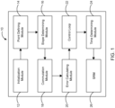
- FIG. 1 illustrates a block diagram of a switched reluctance machine (SRM) control system 10 for controlling an SRM 26.
- the SRM control system 10 enables adaptive pulse positioning over a wide range of speeds and loads.
- the SRM control system 10 includes an initialization module 12 to provide an initial rotor position for the SRM 26 utilizing an initialization mechanism.
- the initialization mechanism is adaptable to implement several approaches like hard alignment or any other mathematical approach.
- a point defining module 14 in the SRM control system 10 defines a pinned point on a phase current waveform during an initial current rise phase of the current waveform. The defined pinned point is static with respect to an underlying inductance value of the SRM 26 and is a function of desired operating point.
- the PI controller for the speed loop controls the amount of time from x (pinned point) to the turn on of the next phase. If demand for speed changes then the demand for current also changes. This means that the slopes are different and requires change in the pinned point.
- the pinned point is defined at a specifically chosen magnitude of current between 50% and 100% of the steady state current on the initial current rise, particularly when there is a sudden change in the operating condition (load torque). This can also be useful in improving accuracy as we enter single pulse mode and the current waveform begins to plateau as the waveform gets closer to the aligned position. The goal is to have the pinned point low enough or far enough from the curved profile of current.
- the first option depends on the knowledge of inductance value for this current for the new operating condition or can be calculated.
- the second option is that, if simplifications in the control methodology allow, only the slope of the current profile (desired current rise) over a fixed time period based on this inductance is needed.
- a slope determining module 16 determines a slope 42 (see FIG. 3 ) of the current rise as the current waveform reaches the pinned point.
- the slope of the current (rise) is measured as the waveform reaches the pinned current level.
- the inductance profile also changes with it. This means the angle corresponding to the pinned position must be changed until the same slope is arrived as was arrived at the previous case.
- a commutation module 18 is designed to receive the slope 42 of the current rise from the slope determining module 16.
- the SRM control system 10 further comprises an error calculating module 20 to calculate an error signal.
- the SRM control system 10 is designed to utilize the underlying inductance or the measured current rise to calculate the error signal.
- the slope 42 of the current rise is utilized to calculate the underlying inductance which is used to calculate the error signal from the desired inductance.
- the SRM control system 10 is designed to utilize the measured current rise over a fixed time period to calculate the error signal from a desired current rise.
- the error signal from the calculated inductance or current slope is used as an input to a control loop 22 in the SRM control system 10.
- a time determining module 24 determines an optimum time T on , T off 40 (see FIG. 3 ) to fire a next pulse.
- the optimum time T on , T off 40 turns a plurality of switches of the SRM 26 to on and off states.
- position is determined to fire a next pulse.
- FIG. 3 shows an overall control architecture of the SRM control system 10 with speed and current loops.
- a reference speed (Ref Speed) 32 or torque is provided as an input to the system 10.
- the proposed method for controlling SRM 26 utilizes a current feedback.
- the slope 42 of the current rise is calculated as the current waveform reaches the pinned point and is fed to the commutation module 18.
- the underlying inductance value is calculated utilizing the slope 42 of the current rise.
- Frequency input signal T p 44 is the other input provided to the commutation module 18 that gives a digital estimate for shaft speed.
- a current speed 36 is calculated utilizing the slope 42 of the current rise and frequency input signal T p 44.
- the error generator between the reference speed 32 and the current speed 36 is processed through a regulator unit 30 that generates a commanded current (I cmd ) 34.
- the regulator unit 30 may be a proportional-integral (PI) regulator.
- the commanded current 34 is compared with a measured current (I phase ) 38 by an inner current loop in the SRM control system 10 to generate pulse width modulation (PWM) signals.
- PWM signals create a plurality of commutation angles for turning the plurality of switches of the SRM 26 to on and off states utilizing the time signals T on , T off 40 .
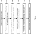
- FIG. 4 shows a flowchart of a method for controlling the SRM 26 utilizing the SRM control system 10.
- the SRM control system having the commutation module is provided.
- the initial rotor position is provided to the SRM utilizing the initialization mechanism as shown in block 52.
- the pinned point on the phase current waveform is defined during the initial current rise phase of the current waveform as indicated at block 54.
- the slope of the current rise is determined as the current waveform reaches the pinned point as shown in block 56.
- the slope is then fed to the commutation module.
- the error signal from the calculated inductance or current slope is used as an input to a control loop in the SRM control system as shown in block 58.
- the time determining module determines an optimum time signal to fire the next pulse as indicated at block 60.
- the optimum time signal is fed to SRM for turning the plurality of SRM switches to on and off states.
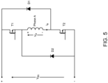
- FIG. 5 shows an asymmetric bridge configuration typically used for controlling the SRM 26. This configuration has each phase connected between two switches T1, T2 which allows independent control and ensures that the inverter does not have a shoot-through failure.
- the turn-on and turn-off signals 40 in FIG. 3 are used to control switches T1 and T2.
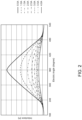
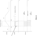
- FIG. 6 shows a current waveform for a three-phase machine.
- "x" is the pinned point of the current waveform in phase A of the machine.
- the pinned point is roughly at 80% of steady state current for the operating condition.
- Optimum efficiency and greatest load capacity of the SRM is obtained when the pinned point of the current waveform is near the top of the initial rise of the current waveform and the point on the inductance profile it is pinned to is near the start of the inductance rise for that phase of the machine.
- the feedback from one commutation pulse is used for the positioning of the next pulse.
- the feedback from this pulse could be used to adjust the position of the next pulse in the same phase, or the next time that specific stator rotor pole combination is reached, or anything in between.
- each pulse to modify only pulses of the same phase has the benefit of allowing phases to be adjusted independently due to non-uniform inductance on each phase; however, the position feedback is slower by a multiple of the number of phases in the machine. This could be overcome by using the error of the current pulse to input to two control loops. Among the two control loops, one adjusts the current phase and the other adjusts all of the phases allowing for both minor adjustments between phases while still achieving rapid feedback to the main control methodology.
- an event base control loop was utilized. Any form of control loop operating from the error between the desired inductance (or desired current rise) and the measured inductance (or measured current rise) meets the intent of the preferred embodiment.
- the current was pinned on the initial rising edge of the pulse; however, any point along an arbitrary waveform can be used as the pinned point.
- the current rise was used at the specified point on the current rise; however, at the desired waveform position, the phase could be switched off or freewheeled and the current drop/decay at that point could be used in the same manner to control position.
- the output of the control loop is the desired time between pulses and when the time from the last pulse is reached, the next pulse is fired.
- the output of the control loop could also be tuned such that it is the desired position on a software encoder which is being updated continuously based on the speed estimations. This methodology induces further error because the software encoder is prone to drift due to error in the speed measurements but would achieve the same effect.
- a hardware encoder could be used and this methodology could position the pulses relative to the hardware encoder.
- This methodology could be extended further to allow for adjustments in the desired inductance (or desired current rise) based on speed, load, or desired optimization. These adjustments could be applied from a lookup table based on current operating point or calculated real time based on an adjustment formula.
Landscapes
- Engineering & Computer Science (AREA)
- Power Engineering (AREA)
- Control Of Electric Motors In General (AREA)
Claims (7)
- Verfahren zum Steuern einer geschalteten Reluktanzmaschine, SRM, welches die folgenden Schritte umfasst:a) Bereitstellen (50) eines SRM-Steuersystems (10) mit einem Kommutierungsmodul (18);b) Bereitstellen (52) einer Anfangsrotorposition für die SRM unter Nutzung eines Initialisierungsmechanismus;c) Definieren (54) eines festgelegten Punkts (x) auf einer Phasenstromwellenform während einer anfänglichen Stromanstiegsphase der Stromwellenform, wobei die Stromwellenform gemäß einem Induktivitätsanstieg (Θon) einer Phase (A) der SRM anzusteigen beginnt, wobei der festgelegte Punkt (x) an einem Punkt definiert ist, der einem Betrag zwischen 50 % und 100 % des stationären Stroms bei dem anfänglichen Stromanstieg entspricht;d) Bestimmen (56) einer Steigung (42) des Stromanstiegs, wenn die Stromwellenform den festgelegten Punkt (x) erreicht, wobei die Steigung (42) in das Kommutierungsmodul (18) eingespeist wird;e) Berechnen (58) eines Fehlersignals und Liefern des Fehlersignals als eine Eingabe an eine Steuerschleife (22) in dem SRM-Steuersystem (10), wobei bei einer Konfiguration die Steigung (42) des Stromanstiegs genutzt wird, um einen zugrundliegenden Induktivitätswert der SRM zu berechnen, der zum Berechnen des Fehlersignals aus einer gewünschten Induktivität verwendet wird, und wobei bei einer anderen Konfiguration das SRM-Steuersystem (10) zum Nutzen des gemessenen Stromanstiegs über eine feste Zeitperiode gestaltet ist, um das Fehlersignal aus einem gewünschten Stromanstieg zu berechnen;f) Bestimmen (60) einer optimalen Zeit (40) zum Auslösen eines nächsten Impulses;wobei das SRM-Steuersystem (10) eine adaptive Impulspositionierung über einen breiten Bereich von Geschwindigkeiten und Lasten ermöglicht.
- Verfahren nach Anspruch 1, wobei der definierte festgelegte Punkt (x) statisch mit Bezug auf den zugrundeliegenden Induktivitätswert der SRM ist.
- Verfahren zum Steuern einer SRM nach Anspruch 1, und das ferner die folgenden Schritte umfasst:g) Liefern eines Frequenzeingabesignals (44) an das Kommutierungsmodul (18), um eine digitale Schätzung für eine Wellengeschwindigkeit zu erhalten;h) Berechnen einer aktuellen Geschwindigkeit (36) und des optimalen Zeitsignals zum Auslösen des nächsten Impulses (40) unter Nutzung der Steigung (42) des Stromanstiegs und Frequenzeingabesignals (44);i) Erzeugen eines angewiesenen Stroms (Icmd) durch eine Reglereinheit (30) unter Nutzung einer Referenzgeschwindigkeit (32) und der Stromgeschwindigkeit (36);j) Vergleichen des angewiesenen Stroms (Icmd) mit einem gemessenen Strom (Iphase) durch eine innere Stromschleife in dem SRM-Steuersystem (10); undk) unter Nutzung des optimalen Zeitsignals zum Auslösen des nächsten Impulses (40), Erzeugen von Pulsweitenmodulation(PWM)-Signalen, um mehrere Kommutierungswinkel zum Schalten mehrerer Schalter (T1, T2) der SRM in einen Ein- und Aus-Zustand zu erschaffen.
- Verfahren nach Anspruch 3, wobei die Reglereinheit eine Proportional-Integral-Einheit ist.
- Geschaltete-Reluktanzmaschine- bzw. SRM-Steuersystem (10) zum Steuern einer SRM, wobei das System (10) Folgendes umfasst:ein Initialisierungsmodul (12) zum Bereitstellen einer Anfangsrotorposition für die SRM unter Nutzung eines Initialisierungsmechanismus;ein Punktdefinitionsmodul (14) zum Definieren eines festgelegten Punkts (x) auf einer Phasenstromwellenform während einer anfänglichen Stromanstiegsphase der Stromwellenform, wobei die Stromwellenform gemäß einem Induktivitätsanstieg (Θon) einer Phase (A) der SRM anzusteigen beginnt, wobei der festgelegte Punkt (x) an einem Punkt definiert ist, der einem Betrag zwischen 50 % und 100 % des stationären Stroms bei dem anfänglichen Stromanstieg entspricht;ein Steigungsbestimmungsmodul (16) zum Bestimmen einer Steigung (42) des Stromanstiegs, wenn die Stromwellenform den festgelegten Punkt (x) erreicht;ein Kommutierungsmodul (18) zum Empfangen der Steigung (42) des Stromanstiegs von dem Steigungsbestimmungsmodul (16) und eines Frequenzeingabesignals (44);ein Fehlerberechnungsmodul (20) zum Berechnen eines Fehlersignals zur Einspeisung in eine Steuerschleife (22) in dem SRM-Steuersystem (10), wobei bei einer Konfiguration die Steigung (42) des Stromanstiegs genutzt wird, um einen zugrundliegenden Induktivitätswert der SRM zu berechnen, der zum Berechnen des Fehlersignals aus einer gewünschten Induktivität verwendet wird, und wobei bei einer anderen Konfiguration das SRM-Steuersystem (10) zum Nutzen des gemessenen Stromanstiegs über eine feste Zeitperiode gestaltet ist, um das Fehlersignal aus einem gewünschten Stromanstieg zu berechnen; undein Zeitbestimmungsmodul (24) zum Bestimmen einer optimalen Zeit (40) zum Auslösen eines nächsten Impulses; wobei das SRM-Steuersystem eine adaptive Impulspositionierung über einen breiten Bereich von Geschwindigkeiten und Lasten ermöglicht.
- SRM-Steuersystem (10) nach Anspruch 5, wobei der definierte festgelegte Punkt (x) statisch mit Bezug auf einen zugrundeliegenden Induktivitätswert der SRM ist.
- SRM-Steuersystem (10) nach Anspruch 5, wobei die optimale Zeit (40), die von dem Zeitbestimmungsmodul (24) bestimmt wird, zum Schalten mehrerer Schalter (T1, T2) der SRM in einen Ein- und Aus-Zustand genutzt wird.
Applications Claiming Priority (1)
| Application Number | Priority Date | Filing Date | Title |
|---|---|---|---|
| PCT/US2018/025609 WO2019190569A1 (en) | 2018-03-31 | 2018-03-31 | Manufacturing-sensitive control of high rotor pole switched reluctance motors |
Publications (3)
| Publication Number | Publication Date |
|---|---|
| EP3665770A1 EP3665770A1 (de) | 2020-06-17 |
| EP3665770A4 EP3665770A4 (de) | 2020-08-05 |
| EP3665770B1 true EP3665770B1 (de) | 2025-03-19 |
Family
ID=68060437
Family Applications (1)
| Application Number | Title | Priority Date | Filing Date |
|---|---|---|---|
| EP18912891.1A Active EP3665770B1 (de) | 2018-03-31 | 2018-03-31 | Verfahren und system zur steuerung einer geschalteten reluktanzmaschine |
Country Status (8)
| Country | Link |
|---|---|
| US (3) | US11165382B2 (de) |
| EP (1) | EP3665770B1 (de) |
| JP (1) | JP2021518096A (de) |
| KR (1) | KR102522435B1 (de) |
| CN (1) | CN111406364A (de) |
| AU (1) | AU2018415583B2 (de) |
| CA (1) | CA3072011C (de) |
| WO (1) | WO2019190569A1 (de) |
Families Citing this family (11)
| Publication number | Priority date | Publication date | Assignee | Title |
|---|---|---|---|---|
| US8487759B2 (en) | 2009-09-30 | 2013-07-16 | Apple Inc. | Self adapting haptic device |
| AU2016100399B4 (en) | 2015-04-17 | 2017-02-02 | Apple Inc. | Contracting and elongating materials for providing input and output for an electronic device |
| US11380470B2 (en) * | 2019-09-24 | 2022-07-05 | Apple Inc. | Methods to control force in reluctance actuators based on flux related parameters |
| US20230163709A1 (en) * | 2020-04-08 | 2023-05-25 | Turntide Technologies Inc. | Method for sensorless current profiling in a switched reluctance machine |
| US11545922B2 (en) | 2021-01-21 | 2023-01-03 | Caterpillar Inc. | Power based pulse injection control for SR self sensing |
| US11977683B2 (en) | 2021-03-12 | 2024-05-07 | Apple Inc. | Modular systems configured to provide localized haptic feedback using inertial actuators |
| US11809631B2 (en) | 2021-09-21 | 2023-11-07 | Apple Inc. | Reluctance haptic engine for an electronic device |
| CN114039516B (zh) * | 2021-11-04 | 2023-11-10 | 南京邮电大学 | 基于高频脉冲注入的无轴承开关磁阻电机的优化控制方法 |
| JP2025525462A (ja) | 2022-06-27 | 2025-08-05 | アントロポセン・インスティテュート・エルエルシー | 軸方向磁束スイッチリラクタンスおよびインダクタンス状態機械システム、デバイス、および方法 |
| US12149134B2 (en) | 2022-06-27 | 2024-11-19 | Anthropocene Institute LLC | Axial flux switched reluctance motor and generator, and related systems and methods |
| CN121000115B (zh) * | 2025-10-27 | 2026-02-06 | 成都航天凯特机电科技有限公司 | 基于直流无刷电机控制扇区换向补偿方法 |
Family Cites Families (22)
| Publication number | Priority date | Publication date | Assignee | Title |
|---|---|---|---|---|
| US5015939A (en) | 1990-08-10 | 1991-05-14 | Synektron Corporation | Control circuit for switched reluctance motor |
| GB9211685D0 (en) | 1992-06-03 | 1992-07-15 | Switched Reluctance Drives Ltd | Sensorless rotor position measurement |
| US5986418A (en) | 1994-01-28 | 1999-11-16 | Emerson Electric Co. | Noise reduction in a switched reluctance motor by current profile manipulation |
| GB9525952D0 (en) | 1995-12-19 | 1996-02-21 | Switched Reluctance Drives Ltd | Sensorless rotor position monitoring in reluctance machines |
| DE19628585C2 (de) * | 1996-07-16 | 2001-12-20 | Danfoss As | Verfahren zum Kommutieren eines bürstenlosen Motors und Speiseschaltung für einen bürstenlosen Motor |
| US5786681A (en) * | 1996-11-15 | 1998-07-28 | Dana Corporation | Active phase coil inductance sensing |
| US6107772A (en) * | 1997-09-26 | 2000-08-22 | Dana Corporation | Sensorless switched reluctance motor control |
| US6472842B1 (en) | 1997-10-03 | 2002-10-29 | The Texas A&M University System | Self-tuning control of switched-reluctance motor drive system |
| US6288514B1 (en) | 1998-10-02 | 2001-09-11 | Texas Instruments Incorporated | Commutation method and apparatus for switched reluctance motor |
| GB0100552D0 (en) | 2001-01-09 | 2001-02-21 | Switched Reluctance Drives Ltd | A method and system for determining rotor position in a switched reluctance machine |
| GB0113776D0 (en) * | 2001-06-06 | 2001-07-25 | Switched Reluctance Drives Ltd | Excitation of switched reluctance motors |
| US6646407B2 (en) | 2001-06-08 | 2003-11-11 | General Motors Corporation | Electric motor control having DC-DC converter and method of using same |
| US6801012B1 (en) | 2003-03-31 | 2004-10-05 | Delphi Technologies, Inc. | Sensorless control of switched reluctance electric machines |
| KR101152083B1 (ko) * | 2003-04-24 | 2012-06-11 | 니덱 에스알 드라이브즈 리미티드 | 전기 기기의 회전자 위치 검출 방법 및 시스템과, 전기 기기의 회전자 위치 검출 방법을 실행하기 위한 소프트웨어를 기록한 컴퓨터가 읽을 수 있는 기록매체 |
| JP5501231B2 (ja) * | 2007-08-14 | 2014-05-21 | ラム インク | 単一スイッチ方式のスイッチドリラクタンス機を制御する方法、制御装置、および電力変換装置 |
| US8810188B2 (en) | 2009-04-30 | 2014-08-19 | Iqbal Husain | Position estimation at starting and lower speeds in three-phase switched reluctance machines |
| KR101301385B1 (ko) * | 2011-09-20 | 2013-09-10 | 삼성전기주식회사 | 스위치드 릴럭턴스 모터의 속도 제어 장치 |
| KR101334745B1 (ko) * | 2012-09-03 | 2013-11-29 | 원광대학교산학협력단 | 스위치드 릴럭턴스 모터의 스위칭 각 제어장치 |
| KR20160102205A (ko) | 2013-12-27 | 2016-08-29 | 발레오 에어 매니지먼트 유케이 리미티드 | 모터 코일 타이밍 방법 |
| AU2016215158B2 (en) * | 2015-02-04 | 2018-04-19 | Turntide Technologies Inc. | Reliable control of high rotor pole switched reluctance machine |
| EP3125424A1 (de) * | 2015-07-28 | 2017-02-01 | Perkins Engines Company Limited | Verfahren zur steuerung einer geschalteten reluktanzmaschine |
| CN107241033B (zh) * | 2017-08-01 | 2019-08-23 | 桂林电子科技大学 | 基于电流-位置的开关磁阻电机转矩脉动抑制方法与系统 |
-
2018
- 2018-03-31 EP EP18912891.1A patent/EP3665770B1/de active Active
- 2018-03-31 KR KR1020207025352A patent/KR102522435B1/ko active Active
- 2018-03-31 US US16/767,190 patent/US11165382B2/en active Active
- 2018-03-31 AU AU2018415583A patent/AU2018415583B2/en not_active Ceased
- 2018-03-31 JP JP2020528453A patent/JP2021518096A/ja active Pending
- 2018-03-31 CN CN201880076459.6A patent/CN111406364A/zh active Pending
- 2018-03-31 CA CA3072011A patent/CA3072011C/en active Active
- 2018-03-31 WO PCT/US2018/025609 patent/WO2019190569A1/en not_active Ceased
-
2021
- 2021-11-01 US US17/516,044 patent/US11601081B2/en active Active
-
2023
- 2023-03-02 US US18/116,508 patent/US12132427B2/en active Active
Also Published As
| Publication number | Publication date |
|---|---|
| JP2021518096A (ja) | 2021-07-29 |
| CN111406364A (zh) | 2020-07-10 |
| CA3072011A1 (en) | 2019-10-03 |
| AU2018415583B2 (en) | 2021-01-21 |
| US11601081B2 (en) | 2023-03-07 |
| WO2019190569A1 (en) | 2019-10-03 |
| KR102522435B1 (ko) | 2023-04-17 |
| KR20200120659A (ko) | 2020-10-21 |
| NZ761486A (en) | 2021-11-26 |
| US11165382B2 (en) | 2021-11-02 |
| US12132427B2 (en) | 2024-10-29 |
| EP3665770A1 (de) | 2020-06-17 |
| EP3665770A4 (de) | 2020-08-05 |
| US20200389114A1 (en) | 2020-12-10 |
| US20230208336A1 (en) | 2023-06-29 |
| AU2018415583A1 (en) | 2020-02-27 |
| US20220060132A1 (en) | 2022-02-24 |
| CA3072011C (en) | 2022-03-22 |
Similar Documents
| Publication | Publication Date | Title |
|---|---|---|
| EP3665770B1 (de) | Verfahren und system zur steuerung einer geschalteten reluktanzmaschine | |
| US4961038A (en) | Torque estimator for switched reluctance machines | |
| US9998059B2 (en) | Motor driving apparatus | |
| JP5403765B2 (ja) | 電気機械の制御 | |
| US8970146B2 (en) | Controller for electrical machines | |
| EP2232695B1 (de) | Steuerung elektrischer maschinen | |
| WO1988002951A1 (en) | A motor energizing circuit | |
| JP2023027104A (ja) | スイッチト・リラクタンス・モータ駆動の準センサレス適応制御のための方法及び装置 | |
| US7141945B2 (en) | Method and apparatus for controlling motor drive | |
| US6359413B1 (en) | Current control system for a switched reluctance motor | |
| JP3472533B2 (ja) | モータ制御装置 | |
| WO2019101372A1 (en) | Control system for controlling a switched reluctance machine, a switched reluctance machine, an appliance and a method | |
| JP2021048664A (ja) | 制御装置及びモータ駆動システム | |
| NZ761486B2 (en) | Manufacturing-sensitive control of high rotor pole switched reluctance motors | |
| JP4134716B2 (ja) | 電動機の電流制御装置 | |
| HK40026559A (en) | Manufacturing-sensitive control of high rotor pole switched reluctance motors | |
| KR20210073596A (ko) | 무브러시 영구 자석 모터의 제어 방법 | |
| JPH04334994A (ja) | ブラシレスdcモータの駆動制御装置 |
Legal Events
| Date | Code | Title | Description |
|---|---|---|---|
| STAA | Information on the status of an ep patent application or granted ep patent |
Free format text: STATUS: THE INTERNATIONAL PUBLICATION HAS BEEN MADE |
|
| PUAI | Public reference made under article 153(3) epc to a published international application that has entered the european phase |
Free format text: ORIGINAL CODE: 0009012 |
|
| STAA | Information on the status of an ep patent application or granted ep patent |
Free format text: STATUS: REQUEST FOR EXAMINATION WAS MADE |
|
| 17P | Request for examination filed |
Effective date: 20200311 |
|
| AK | Designated contracting states |
Kind code of ref document: A1 Designated state(s): AL AT BE BG CH CY CZ DE DK EE ES FI FR GB GR HR HU IE IS IT LI LT LU LV MC MK MT NL NO PL PT RO RS SE SI SK SM TR |
|
| AX | Request for extension of the european patent |
Extension state: BA ME |
|
| A4 | Supplementary search report drawn up and despatched |
Effective date: 20200702 |
|
| RIC1 | Information provided on ipc code assigned before grant |
Ipc: H02P 8/34 20060101ALI20200626BHEP Ipc: H02P 6/20 20160101ALI20200626BHEP Ipc: H02P 25/086 20160101ALI20200626BHEP Ipc: H02P 25/098 20160101ALI20200626BHEP Ipc: H02P 25/089 20160101ALI20200626BHEP Ipc: H02P 6/10 20060101AFI20200626BHEP Ipc: H02P 6/185 20160101ALI20200626BHEP Ipc: H02P 6/14 20160101ALI20200626BHEP Ipc: H02P 6/18 20160101ALI20200626BHEP Ipc: H02P 6/17 20160101ALI20200626BHEP Ipc: H02P 6/16 20160101ALI20200626BHEP Ipc: H02P 25/092 20160101ALI20200626BHEP Ipc: H02P 8/12 20060101ALI20200626BHEP Ipc: H02P 1/16 20060101ALI20200626BHEP |
|
| RAP1 | Party data changed (applicant data changed or rights of an application transferred) |
Owner name: TURNTIDE TECHNOLOGIES INC. |
|
| DAV | Request for validation of the european patent (deleted) | ||
| DAX | Request for extension of the european patent (deleted) | ||
| STAA | Information on the status of an ep patent application or granted ep patent |
Free format text: STATUS: EXAMINATION IS IN PROGRESS |
|
| 17Q | First examination report despatched |
Effective date: 20211124 |
|
| REG | Reference to a national code |
Ref country code: DE Ref legal event code: R079 Free format text: PREVIOUS MAIN CLASS: H02P0006100000 Ipc: H02P0025086000 Ref country code: DE Ref legal event code: R079 Ref document number: 602018080365 Country of ref document: DE Free format text: PREVIOUS MAIN CLASS: H02P0006100000 Ipc: H02P0025086000 |
|
| GRAP | Despatch of communication of intention to grant a patent |
Free format text: ORIGINAL CODE: EPIDOSNIGR1 |
|
| STAA | Information on the status of an ep patent application or granted ep patent |
Free format text: STATUS: GRANT OF PATENT IS INTENDED |
|
| RIC1 | Information provided on ipc code assigned before grant |
Ipc: H02P 6/18 20160101ALN20241018BHEP Ipc: H02P 1/16 20060101ALN20241018BHEP Ipc: H02P 6/185 20160101ALI20241018BHEP Ipc: H02P 6/20 20160101ALI20241018BHEP Ipc: H02P 8/12 20060101ALI20241018BHEP Ipc: H02P 8/34 20060101ALI20241018BHEP Ipc: H02P 25/089 20160101ALI20241018BHEP Ipc: H02P 25/092 20160101ALI20241018BHEP Ipc: H02P 25/098 20160101ALI20241018BHEP Ipc: H02P 25/086 20160101AFI20241018BHEP |
|
| INTG | Intention to grant announced |
Effective date: 20241031 |
|
| GRAS | Grant fee paid |
Free format text: ORIGINAL CODE: EPIDOSNIGR3 |
|
| GRAA | (expected) grant |
Free format text: ORIGINAL CODE: 0009210 |
|
| STAA | Information on the status of an ep patent application or granted ep patent |
Free format text: STATUS: THE PATENT HAS BEEN GRANTED |
|
| AK | Designated contracting states |
Kind code of ref document: B1 Designated state(s): AL AT BE BG CH CY CZ DE DK EE ES FI FR GB GR HR HU IE IS IT LI LT LU LV MC MK MT NL NO PL PT RO RS SE SI SK SM TR |
|
| REG | Reference to a national code |
Ref country code: GB Ref legal event code: FG4D |
|
| REG | Reference to a national code |
Ref country code: CH Ref legal event code: EP |
|
| REG | Reference to a national code |
Ref country code: DE Ref legal event code: R096 Ref document number: 602018080365 Country of ref document: DE |
|
| REG | Reference to a national code |
Ref country code: IE Ref legal event code: FG4D |
|
| PG25 | Lapsed in a contracting state [announced via postgrant information from national office to epo] |
Ref country code: RS Free format text: LAPSE BECAUSE OF FAILURE TO SUBMIT A TRANSLATION OF THE DESCRIPTION OR TO PAY THE FEE WITHIN THE PRESCRIBED TIME-LIMIT Effective date: 20250619 |
|
| PG25 | Lapsed in a contracting state [announced via postgrant information from national office to epo] |
Ref country code: FI Free format text: LAPSE BECAUSE OF FAILURE TO SUBMIT A TRANSLATION OF THE DESCRIPTION OR TO PAY THE FEE WITHIN THE PRESCRIBED TIME-LIMIT Effective date: 20250319 |
|
| REG | Reference to a national code |
Ref country code: LT Ref legal event code: MG9D |
|
| PG25 | Lapsed in a contracting state [announced via postgrant information from national office to epo] |
Ref country code: NO Free format text: LAPSE BECAUSE OF FAILURE TO SUBMIT A TRANSLATION OF THE DESCRIPTION OR TO PAY THE FEE WITHIN THE PRESCRIBED TIME-LIMIT Effective date: 20250619 |
|
| PG25 | Lapsed in a contracting state [announced via postgrant information from national office to epo] |
Ref country code: HR Free format text: LAPSE BECAUSE OF FAILURE TO SUBMIT A TRANSLATION OF THE DESCRIPTION OR TO PAY THE FEE WITHIN THE PRESCRIBED TIME-LIMIT Effective date: 20250319 |
|
| PG25 | Lapsed in a contracting state [announced via postgrant information from national office to epo] |
Ref country code: LV Free format text: LAPSE BECAUSE OF FAILURE TO SUBMIT A TRANSLATION OF THE DESCRIPTION OR TO PAY THE FEE WITHIN THE PRESCRIBED TIME-LIMIT Effective date: 20250319 |
|
| PG25 | Lapsed in a contracting state [announced via postgrant information from national office to epo] |
Ref country code: GR Free format text: LAPSE BECAUSE OF FAILURE TO SUBMIT A TRANSLATION OF THE DESCRIPTION OR TO PAY THE FEE WITHIN THE PRESCRIBED TIME-LIMIT Effective date: 20250620 Ref country code: BG Free format text: LAPSE BECAUSE OF FAILURE TO SUBMIT A TRANSLATION OF THE DESCRIPTION OR TO PAY THE FEE WITHIN THE PRESCRIBED TIME-LIMIT Effective date: 20250319 |
|
| REG | Reference to a national code |
Ref country code: NL Ref legal event code: MP Effective date: 20250319 |
|
| REG | Reference to a national code |
Ref country code: AT Ref legal event code: MK05 Ref document number: 1777803 Country of ref document: AT Kind code of ref document: T Effective date: 20250319 |
|
| PG25 | Lapsed in a contracting state [announced via postgrant information from national office to epo] |
Ref country code: NL Free format text: LAPSE BECAUSE OF FAILURE TO SUBMIT A TRANSLATION OF THE DESCRIPTION OR TO PAY THE FEE WITHIN THE PRESCRIBED TIME-LIMIT Effective date: 20250319 |
|
| PG25 | Lapsed in a contracting state [announced via postgrant information from national office to epo] |
Ref country code: SE Free format text: LAPSE BECAUSE OF FAILURE TO SUBMIT A TRANSLATION OF THE DESCRIPTION OR TO PAY THE FEE WITHIN THE PRESCRIBED TIME-LIMIT Effective date: 20250319 |
|
| REG | Reference to a national code |
Ref country code: DE Ref legal event code: R119 Ref document number: 602018080365 Country of ref document: DE |
|
| PG25 | Lapsed in a contracting state [announced via postgrant information from national office to epo] |
Ref country code: SM Free format text: LAPSE BECAUSE OF FAILURE TO SUBMIT A TRANSLATION OF THE DESCRIPTION OR TO PAY THE FEE WITHIN THE PRESCRIBED TIME-LIMIT Effective date: 20250319 |
|
| PG25 | Lapsed in a contracting state [announced via postgrant information from national office to epo] |
Ref country code: PT Free format text: LAPSE BECAUSE OF FAILURE TO SUBMIT A TRANSLATION OF THE DESCRIPTION OR TO PAY THE FEE WITHIN THE PRESCRIBED TIME-LIMIT Effective date: 20250721 Ref country code: ES Free format text: LAPSE BECAUSE OF FAILURE TO SUBMIT A TRANSLATION OF THE DESCRIPTION OR TO PAY THE FEE WITHIN THE PRESCRIBED TIME-LIMIT Effective date: 20250319 |
|
| PG25 | Lapsed in a contracting state [announced via postgrant information from national office to epo] |
Ref country code: PL Free format text: LAPSE BECAUSE OF FAILURE TO SUBMIT A TRANSLATION OF THE DESCRIPTION OR TO PAY THE FEE WITHIN THE PRESCRIBED TIME-LIMIT Effective date: 20250319 Ref country code: IT Free format text: LAPSE BECAUSE OF FAILURE TO SUBMIT A TRANSLATION OF THE DESCRIPTION OR TO PAY THE FEE WITHIN THE PRESCRIBED TIME-LIMIT Effective date: 20250319 |
|
| PG25 | Lapsed in a contracting state [announced via postgrant information from national office to epo] |
Ref country code: AT Free format text: LAPSE BECAUSE OF FAILURE TO SUBMIT A TRANSLATION OF THE DESCRIPTION OR TO PAY THE FEE WITHIN THE PRESCRIBED TIME-LIMIT Effective date: 20250319 |
|
| PG25 | Lapsed in a contracting state [announced via postgrant information from national office to epo] |
Ref country code: EE Free format text: LAPSE BECAUSE OF FAILURE TO SUBMIT A TRANSLATION OF THE DESCRIPTION OR TO PAY THE FEE WITHIN THE PRESCRIBED TIME-LIMIT Effective date: 20250319 Ref country code: CZ Free format text: LAPSE BECAUSE OF FAILURE TO SUBMIT A TRANSLATION OF THE DESCRIPTION OR TO PAY THE FEE WITHIN THE PRESCRIBED TIME-LIMIT Effective date: 20250319 |
|
| PG25 | Lapsed in a contracting state [announced via postgrant information from national office to epo] |
Ref country code: RO Free format text: LAPSE BECAUSE OF FAILURE TO SUBMIT A TRANSLATION OF THE DESCRIPTION OR TO PAY THE FEE WITHIN THE PRESCRIBED TIME-LIMIT Effective date: 20250319 |
|
| REG | Reference to a national code |
Ref country code: CH Ref legal event code: H13 Free format text: ST27 STATUS EVENT CODE: U-0-0-H10-H13 (AS PROVIDED BY THE NATIONAL OFFICE) Effective date: 20251024 |
|
| PG25 | Lapsed in a contracting state [announced via postgrant information from national office to epo] |
Ref country code: SK Free format text: LAPSE BECAUSE OF FAILURE TO SUBMIT A TRANSLATION OF THE DESCRIPTION OR TO PAY THE FEE WITHIN THE PRESCRIBED TIME-LIMIT Effective date: 20250319 |
|
| PG25 | Lapsed in a contracting state [announced via postgrant information from national office to epo] |
Ref country code: IS Free format text: LAPSE BECAUSE OF FAILURE TO SUBMIT A TRANSLATION OF THE DESCRIPTION OR TO PAY THE FEE WITHIN THE PRESCRIBED TIME-LIMIT Effective date: 20250719 |
|
| PG25 | Lapsed in a contracting state [announced via postgrant information from national office to epo] |
Ref country code: LU Free format text: LAPSE BECAUSE OF NON-PAYMENT OF DUE FEES Effective date: 20250331 |
|
| REG | Reference to a national code |
Ref country code: BE Ref legal event code: MM Effective date: 20250331 |
|
| PG25 | Lapsed in a contracting state [announced via postgrant information from national office to epo] |
Ref country code: MC Free format text: LAPSE BECAUSE OF FAILURE TO SUBMIT A TRANSLATION OF THE DESCRIPTION OR TO PAY THE FEE WITHIN THE PRESCRIBED TIME-LIMIT Effective date: 20250319 |
|
| PG25 | Lapsed in a contracting state [announced via postgrant information from national office to epo] |
Ref country code: DE Free format text: LAPSE BECAUSE OF NON-PAYMENT OF DUE FEES Effective date: 20251001 |
|
| PG25 | Lapsed in a contracting state [announced via postgrant information from national office to epo] |
Ref country code: DK Free format text: LAPSE BECAUSE OF FAILURE TO SUBMIT A TRANSLATION OF THE DESCRIPTION OR TO PAY THE FEE WITHIN THE PRESCRIBED TIME-LIMIT Effective date: 20250319 |
|
| PG25 | Lapsed in a contracting state [announced via postgrant information from national office to epo] |
Ref country code: BE Free format text: LAPSE BECAUSE OF NON-PAYMENT OF DUE FEES Effective date: 20250331 |
|
| PG25 | Lapsed in a contracting state [announced via postgrant information from national office to epo] |
Ref country code: CH Free format text: LAPSE BECAUSE OF NON-PAYMENT OF DUE FEES Effective date: 20250331 |
|
| PG25 | Lapsed in a contracting state [announced via postgrant information from national office to epo] |
Ref country code: IE Free format text: LAPSE BECAUSE OF NON-PAYMENT OF DUE FEES Effective date: 20250331 |
|
| PLBE | No opposition filed within time limit |
Free format text: ORIGINAL CODE: 0009261 |
|
| STAA | Information on the status of an ep patent application or granted ep patent |
Free format text: STATUS: NO OPPOSITION FILED WITHIN TIME LIMIT |
|
| REG | Reference to a national code |
Ref country code: CH Ref legal event code: L10 Free format text: ST27 STATUS EVENT CODE: U-0-0-L10-L00 (AS PROVIDED BY THE NATIONAL OFFICE) Effective date: 20260128 |
|
| 26N | No opposition filed |
Effective date: 20251222 |
|
| PGFP | Annual fee paid to national office [announced via postgrant information from national office to epo] |
Ref country code: GB Payment date: 20260105 Year of fee payment: 9 |
|
| PG25 | Lapsed in a contracting state [announced via postgrant information from national office to epo] |
Ref country code: FR Free format text: LAPSE BECAUSE OF NON-PAYMENT OF DUE FEES Effective date: 20250519 |