EP3665447B1 - Vorrichtung und verfahren zur kapazitiven messung eines füllstands eines füllmediums - Google Patents
Vorrichtung und verfahren zur kapazitiven messung eines füllstands eines füllmediums Download PDFInfo
- Publication number
- EP3665447B1 EP3665447B1 EP18783010.4A EP18783010A EP3665447B1 EP 3665447 B1 EP3665447 B1 EP 3665447B1 EP 18783010 A EP18783010 A EP 18783010A EP 3665447 B1 EP3665447 B1 EP 3665447B1
- Authority
- EP
- European Patent Office
- Prior art keywords
- measuring element
- measuring
- voltage
- filling
- electrical
- Prior art date
- Legal status (The legal status is an assumption and is not a legal conclusion. Google has not performed a legal analysis and makes no representation as to the accuracy of the status listed.)
- Active
Links
Images

Classifications
-
- G—PHYSICS
- G01—MEASURING; TESTING
- G01F—MEASURING VOLUME, VOLUME FLOW, MASS FLOW OR LIQUID LEVEL; METERING BY VOLUME
- G01F23/00—Indicating or measuring liquid level or level of fluent solid material, e.g. indicating in terms of volume or indicating by means of an alarm
- G01F23/22—Indicating or measuring liquid level or level of fluent solid material, e.g. indicating in terms of volume or indicating by means of an alarm by measuring physical variables, other than linear dimensions, pressure or weight, dependent on the level to be measured, e.g. by difference of heat transfer of steam or water
- G01F23/26—Indicating or measuring liquid level or level of fluent solid material, e.g. indicating in terms of volume or indicating by means of an alarm by measuring physical variables, other than linear dimensions, pressure or weight, dependent on the level to be measured, e.g. by difference of heat transfer of steam or water by measuring variations of capacity or inductance of capacitors or inductors arising from the presence of liquid or fluent solid material in the electric or electromagnetic fields
- G01F23/263—Indicating or measuring liquid level or level of fluent solid material, e.g. indicating in terms of volume or indicating by means of an alarm by measuring physical variables, other than linear dimensions, pressure or weight, dependent on the level to be measured, e.g. by difference of heat transfer of steam or water by measuring variations of capacity or inductance of capacitors or inductors arising from the presence of liquid or fluent solid material in the electric or electromagnetic fields by measuring variations in capacitance of capacitors
-
- G—PHYSICS
- G01—MEASURING; TESTING
- G01F—MEASURING VOLUME, VOLUME FLOW, MASS FLOW OR LIQUID LEVEL; METERING BY VOLUME
- G01F23/00—Indicating or measuring liquid level or level of fluent solid material, e.g. indicating in terms of volume or indicating by means of an alarm
- G01F23/22—Indicating or measuring liquid level or level of fluent solid material, e.g. indicating in terms of volume or indicating by means of an alarm by measuring physical variables, other than linear dimensions, pressure or weight, dependent on the level to be measured, e.g. by difference of heat transfer of steam or water
- G01F23/26—Indicating or measuring liquid level or level of fluent solid material, e.g. indicating in terms of volume or indicating by means of an alarm by measuring physical variables, other than linear dimensions, pressure or weight, dependent on the level to be measured, e.g. by difference of heat transfer of steam or water by measuring variations of capacity or inductance of capacitors or inductors arising from the presence of liquid or fluent solid material in the electric or electromagnetic fields
-
- G—PHYSICS
- G01—MEASURING; TESTING
- G01F—MEASURING VOLUME, VOLUME FLOW, MASS FLOW OR LIQUID LEVEL; METERING BY VOLUME
- G01F23/00—Indicating or measuring liquid level or level of fluent solid material, e.g. indicating in terms of volume or indicating by means of an alarm
- G01F23/22—Indicating or measuring liquid level or level of fluent solid material, e.g. indicating in terms of volume or indicating by means of an alarm by measuring physical variables, other than linear dimensions, pressure or weight, dependent on the level to be measured, e.g. by difference of heat transfer of steam or water
- G01F23/26—Indicating or measuring liquid level or level of fluent solid material, e.g. indicating in terms of volume or indicating by means of an alarm by measuring physical variables, other than linear dimensions, pressure or weight, dependent on the level to be measured, e.g. by difference of heat transfer of steam or water by measuring variations of capacity or inductance of capacitors or inductors arising from the presence of liquid or fluent solid material in the electric or electromagnetic fields
- G01F23/263—Indicating or measuring liquid level or level of fluent solid material, e.g. indicating in terms of volume or indicating by means of an alarm by measuring physical variables, other than linear dimensions, pressure or weight, dependent on the level to be measured, e.g. by difference of heat transfer of steam or water by measuring variations of capacity or inductance of capacitors or inductors arising from the presence of liquid or fluent solid material in the electric or electromagnetic fields by measuring variations in capacitance of capacitors
- G01F23/268—Indicating or measuring liquid level or level of fluent solid material, e.g. indicating in terms of volume or indicating by means of an alarm by measuring physical variables, other than linear dimensions, pressure or weight, dependent on the level to be measured, e.g. by difference of heat transfer of steam or water by measuring variations of capacity or inductance of capacitors or inductors arising from the presence of liquid or fluent solid material in the electric or electromagnetic fields by measuring variations in capacitance of capacitors mounting arrangements of probes
Definitions
- the invention relates to a device and a method for capacitively measuring a filling level of a filling medium in a filling volume that can be filled with a filling medium.
- Devices and methods for capacitively measuring a filling level of a filling medium in a filling volume that can be filled with a filling medium are known in principle.
- Corresponding devices or methods are based on the principle of evaluating the electrical capacitance, which changes as a function of the filling level of a filling medium, of a measuring element of a measuring device arranged in a filling volume filled with the filling medium.
- corresponding devices or methods typically provide for deriving the filling level to be measured (directly) from the electrical capacitance, which varies as a function of the filling level.
- the filling medium typically forms the dielectric of an electrical capacitor, and the electrodes of the capacitor are typically formed by measuring elements of the measuring device.
- the complex relative permittivity (hereinafter abbreviated as permittivity) of the filling medium the real part of which reflects the dielectric constant of the filling medium and the imaginary part of which reflects the (specific) electrical conductivity of the filling medium, must be known in order to be able to measure the level.
- measuring devices required for this must include a plurality of electrical capacitors, which regularly results in measuring devices with a comparatively complex structure, in particular due to a required “decoupling” of the electrical capacitors.
- measuring devices with reference measuring elements often only allow a limited measurement between a minimum and a maximum fill level.
- U.S. 5,747,689 discloses a device for capacitive level measurement.
- the invention is based on the object of specifying an improved device for capacitive measurement of a fill level of a filling medium in a filling volume that can be filled with a filling medium.
- the device described herein (hereinafter referred to as "device” for short) is generally used for the capacitive measurement of a filling level of a filling medium in a filling volume that can be filled or filled with a filling medium and is therefore for the capacitive measurement of a filling level of a filling medium in a filling medium that can be filled with a filling medium or filled volume set up.
- the fill level of the filling medium to be measured by means of the device can be electrically conductive or electrically non-conductive.
- the fill medium is typically, but not necessarily, a liquid; the term "filling medium” therefore basically also includes gases and solids.
- a filling medium in the form of a liquid can in particular be an operating liquid, d. H. B. a fuel, a machine, in particular an engine, such as. B. an engine, his or include such an operating fluid.
- the device can serve as a filling level sensor of an engine, in particular an engine, and can be referred to or considered accordingly.
- the fillable or filled filling volume to be measured by means of the device with regard to its filling level is typically defined by the geometric-constructive dimensions of a container or container having the filling volume.
- the filling medium to be measured by means of the device with regard to its fill level is therefore located in a container or container. With a corresponding container or container, it can be z. B. be a tank.
- a first component of the device is a first measuring element.
- the first measuring element can also be referred to or considered as a first measuring electrode.
- the first measuring element can form or serve as a first electrode of a capacitor arrangement formed by the first measuring element and a second measuring element of the device.
- the first measuring element typically has electrically conductive properties on.
- the first measuring element is therefore typically made of an electrically conductive material, such as. B. metal formed or comprises an electrically conductive material.
- the second measuring element can also be referred to or considered as a second measuring electrode.
- the second measuring element can form or serve as a second electrode of a capacitor arrangement formed by the first measuring element and the second measuring element.
- the second measuring element typically has lower or significantly lower electrically conductive properties.
- the second measuring element is therefore typically made of a material that is, in particular, significantly less electrically conductive or a material structure that is, in particular, significantly less electrically conductive, or comprises a material that is, in particular, significantly less electrically conductive or an, in particular significantly, less electrically conductive material structure.
- the two measuring elements are typically arranged at least in sections in the filling volume or, depending on the filling level, are immersed at least in sections in the filling medium.
- the two measuring elements are typically arranged or formed adjacent to each other.
- the adjacent arrangement or design of the two measuring elements is typically selected in such a way that the first and the second measuring element form a capacitor arrangement or a capacitor.
- the first measuring element forms a first electrode of the capacitor arrangement or of the capacitor
- the second measuring element forms a second electrode of the capacitor arrangement or of the capacitor.
- a free or intermediate space is formed between the two measuring elements, which depending on the level, i. H. depending on the filling level, can be filled or is filled with the filling medium.
- the first and/or the second measuring element can be segmented, ie can comprise several measuring element segments forming the first and/or second measuring element.
- the first measuring element is formed by a plurality of measuring element segments forming the first measuring element or comprises a plurality of measuring element segments forming the first measuring element
- the second measuring element is formed by a plurality of second measuring element segments forming the second measuring element or a plurality of first measuring element forming the first Includes measuring element segments
- the respective first and second measuring element segments are typically arranged in such a way that their arrangement in turn allows a capacitor arrangement or a capacitor to be formed or formed.
- the geometric-structural design of the first measuring element and the second measuring element can basically be freely selected with the proviso that the first measuring element and the second measuring element form a capacitor arrangement or a capacitor.
- the two measuring elements are each elongate, so that they each have a distinct longitudinal axis. Consequently, with the proviso that the first measuring element and the second measuring element form a capacitor arrangement or a capacitor, any desired geometric-constructive arrangements of the first and second measuring element are conceivable.
- the first measuring element can, for. B. plate-like or shaped or tubular or shaped.
- the second measuring element can, for. B. plate-like or -shaped or rod-like or - be formed.
- a z. B. plate-like or -shaped or tubular or -shaped first measuring element can form a, optionally integral, part of a housing structure of the device accommodating the first and/or the second measuring element.
- the Z. B. plate-like or -shaped or rod-like or -shaped second measuring element can be accommodated in a housing structure of the device receiving the first and the second measuring element.
- parallel arrangements of these conceivable In the case of plate-like or -shaped configurations of the first and second measuring element, e.g. B. parallel arrangements of these conceivable.
- tube-like or -shaped configurations of the first measuring element and rod-like or rod-shaped configurations of the second measuring element e.g. B. a coaxial arrangement of these conceivable.
- the respective measuring elements can also be formed by certain more or less electrically conductive structures, in particular on a substrate element such as a printed circuit board. Electrically conductive structures (first electrically conductive structures) with a higher electrical conductivity can form the first measuring element, electrically conductive structures (second electrically conductive structures) with a comparatively (significantly) lower electrical conductivity can form the second measuring element.
- first electrically conductive structures with a higher electrical conductivity
- second electrically conductive structures with a comparatively (significantly) lower electrical conductivity
- the respective first and second electrically conductive structures can accordingly be designed to be arranged offset in parallel relative to one another in such a way that they interlock like fingers.
- the arrangement of the respective first and second electrically conductive structures can be selected such that a respective first electrically conductive structure is arranged or formed at least partially in the intermediate space formed between two (immediately) adjacently arranged second electrically conductive structures.
- the second measuring element is such that (during operation of the device) a potential gradient, ie a gradient of an electrical potential, between a first Section of the second measuring element, ie in particular a first free end of the second measuring element, and a second section of the second measuring element, ie in particular a second free end of the second measuring element opposite the first free end of the second measuring element. Consequently, the first section of the second measuring element can be formed in the area of a first free end of the second measuring element or by a first free end of the second measuring element and/or the second section of the second measuring element in the area of a second free end of the second measuring element or by a second be formed free end of the second measuring element.
- the potential gradient that forms between said sections of the second measuring element is typically independent of the filling level of the filling medium.
- the measuring range of the second measuring element typically extends between said sections of the second measuring element.
- the second measuring element can be in the form of a measuring resistor or can comprise at least one of these.
- the formation of the potential gradient between said sections of the second measuring element can therefore be based on the second measuring element being designed as a measuring resistor or comprising at least one such resistor.
- the resistance (value) of the measuring resistor is so large that a corresponding potential gradient can be formed or is forming between the said sections of the second measuring element.
- the voltage generating device is set up to provide or generate a first electrical voltage and a second electrical voltage and to apply them to the second measuring element.
- the voltage generating device can be connected to an internal or external voltage (supply) source, i. H. e.g. B. be connected to a power supply network.
- the first electrical voltage can be equal (in terms of absolute value) to the second electrical voltage.
- the first electrical voltage can also be different (in terms of absolute value) from the second electrical voltage, or vice versa; consequently, the voltage generating device can optionally be set up to generate at least two identical or different electrical voltages.
- the second measuring element can comprise separate voltage application areas, ie for example electrical contacts, to which the electrical voltages provided or generated by the voltage generating device can be or are applied.
- a first voltage application area can be through or in Area of the aforementioned first section, i.e. in particular in the area of a first free end, of the second measuring element.
- a second voltage application area can be arranged through or in the area of the aforementioned second section, i.e. in particular in the area of a second free end, of the second measuring element or be educated.
- the electrical voltages provided or generated by the voltage generating device can each be provided or generated in the form of a voltage pulse that is defined in terms of magnitude and time.
- the voltage generating device can accordingly be set up to provide or generate defined voltage pulses.
- An appropriately set up voltage generating device can, for. B. be designed as a pulse generator or include such.
- a first voltage pulse can be equal to a second voltage pulse.
- a first electrical voltage pulse can also be different (in terms of absolute value) from a second electrical voltage pulse, or vice versa. Consequently, the voltage generating device can optionally be set up to generate at least two identical or different electrical voltage pulses.
- Another component of the device is a control device that is assigned to the voltage generating device and is implemented in hardware and/or software.
- the control device can form a hardware and/or software component of the voltage generating device.
- the control device is set up to control the operation of the voltage generating device in such a way that the first and second electrical voltage are applied to the second measuring element, i. H. in particular to respective first and second voltage application areas of the second measuring element, can be applied or is applied.
- an alternating or alternating application or application of the first and second electrical voltage to the second measuring element d. H. to respective voltage application areas of the second measuring element, it is to be understood in particular that electrical voltages or voltage pulses defined in terms of absolute value are applied alternately or alternately to respective voltage application areas of the second measuring element.
- either the first voltage is applied to the first voltage application area of the second measuring element, while the second voltage is applied to the second voltage application area of the second measuring element, or the second voltage is applied to the first voltage application area of the second measuring element, while the first voltage is applied to the second voltage application area of the second measuring element is present.
- the control device is accordingly set up to control the operation of the voltage generating device in such a way that at the second measuring element, i. H. the first electrical voltage and the second electrical voltage are applied alternately to respective voltage application areas of the second measuring element. Accordingly, the first electrical voltage is applied to the first voltage application area of the second measuring element in a first time interval and the second electrical voltage is applied in a subsequent second time interval, while the second electrical voltage is applied to the second voltage application area of the second measuring element in the first time interval and in the subsequent time interval second time interval, the first electrical voltage is present, or vice versa. In a subsequent third time interval, the first electrical voltage is again present in the first voltage application area of the second measuring element, while the second electrical voltage is again present in the second voltage application area of the second measuring element, and so on.
- a device configured in this way makes it possible to implement an improved principle for capacitively measuring a filling level of a filling medium in a filling volume that can be filled or is filled with a filling medium.
- the principle for capacitive level measurement that can be implemented with the device is based in particular on recording and evaluating the electrical charge or electrical capacitance between the first and second measuring element, which varies depending on the level of the filling medium, via which the level of the Filling medium concluded and this can therefore be determined.
- the second measuring element typically serves as a level-independent voltage divider, which generates a potential gradient along the second measuring element or along the measuring range of the second measuring element.
- the level-dependent voltage division along the second measuring element or along the measuring range of the second measuring element results in a level-dependent weighting of the electrical charge or capacitance between the first and the second measuring element.
- the electric charge between the first and the second measuring element depends in particular on the filling level of the filling medium, on the potential along the potential gradient and on the permittivity of the filling medium - including, as mentioned, the complex relative permittivity of the filling medium, the real part of which is the dielectric constant of the filling medium and whose imaginary part reflects the (specific) electrical conductivity of the filling medium - which, however, is not relevant for the determination of the level to be realized or realizable by means of the device and is therefore negligible.
- the determination of the level to be realized or realizable by means of the device is therefore independent of the permittivity of the filling medium, i. H. also possible without determining the permittivity of the filling medium.
- the device can also include a measuring device implemented in hardware and/or software.
- the measuring device is used to measure the, if necessary changing electrical charge or electrical capacitance between the first and second measuring element during the alternating or alternating application or application of the first and second electrical voltage to the or to the second measuring element, ie in particular the respective first and second voltage application area of the second measuring element.
- the measuring device is therefore set up to measure a first electrical charge between the first and second measuring element while the first electrical voltage is applied to the first voltage application region of the second measuring element and the second electrical voltage is applied to the second voltage application region of the second measuring element, and a second electrical charge to measure charge between the first and second measuring element during the application of the second electrical voltage to the first voltage application area of the second measuring element and the application of the first electrical voltage to the second voltage application area of the second measuring element.
- the measuring device is typically also set up to generate a measuring signal describing the measured charge between the first and the second measuring element during the alternating application of the first and second electrical voltage to the voltage application areas of the second measuring element.
- the measurement signal can contain at least two partial signals, with a first partial signal describing the electrical charge between the first and second measuring element during the application of the first electrical voltage to the first voltage application area of the second measurement element and the application of the second electrical voltage to the second voltage application area of the second measurement element , and a second partial signal describes the electrical charge between the first and second measuring element during the application of the second electrical voltage to the first voltage application area of the second measurement element and the application of the first electrical voltage to the second voltage application area of the second measurement element.
- the device can also include an evaluation device implemented in hardware and/or software.
- the evaluation device can be assigned to the measuring device.
- the evaluation device is for evaluating the measured charge during the alternating application or application of the first and second electrical voltage to the second measuring element, ie in particular the respective voltage application areas of the second measuring element, or for evaluating said Measuring signal set up in terms of the level of the filling medium in the filling volume.
- the evaluation device can include suitable evaluation logic or suitable evaluation algorithms.
- the second measuring element which is typically elongate, can, as also mentioned, be embodied as a measuring resistor or comprise at least one such resistor.
- the measuring resistor can e.g. B. as a resistance element arranged or formed continuously extending along the longitudinal axis of the second measuring element, in particular on a substrate element of the second measuring element, which substrate element may be a printed circuit board.
- An equivalent circuit diagram for a first measuring element and a second measuring element designed accordingly as a measuring resistor or resistance element represents an RC chain with an "infinite" number of RC elements.
- the measuring resistor consists of several discrete electrically conductive elements arranged or formed along the or a longitudinal axis of the second measuring element on a substrate element of the second measuring element, which substrate element, as mentioned, can be a printed circuit board , In particular metallic, surface elements is formed, which are each connected to discrete resistance elements and to the voltage application areas of the second measuring element. Typically, there is an alternating arrangement of corresponding surface elements and corresponding resistance elements.
- An equivalent circuit diagram for a first measuring element and a correspondingly designed second measuring element represents a large number of discrete capacitive surfaces which are connected via electrical resistances.
- the measuring resistor is typically elongated, i. H. extending at least in sections in the longitudinal direction of the second measuring element.
- the measuring resistor and thus the second measuring element can be used in any specific embodiment, e.g. B. also by at least partially, optionally completely, coating a substrate element - this can, as mentioned, be a printed circuit board - be formed with a suitable material.
- the coating can extend (in the longitudinal direction of the second measuring element) uninterruptedly or interrupted between said sections of the second measuring element.
- the coating can be implemented by various, in particular chemical and/or physical, deposition or application or coating techniques, which enable a material application forming a coating; only by way of example is reference to deposition, vapor deposition or imprinting.
- the second measuring element can (additionally) at least in sections, in particular completely, an insulating coating that forms electrical insulation of the second measuring element and is made of a suitable insulating material.
- the second measuring element can be isolated from the filling medium in this way; ie there is no electrical contact between the filling medium and the second measuring element.
- An isolation of the second measuring element brought about by a corresponding isolation coating is typically only necessary when using the device with electrically conductive filling media.
- the insulation coating is therefore basically optional.
- the invention also relates to a measuring assembly for capacitively measuring a filling level of a filling medium in a filling volume that can be filled with a filling medium, in particular for a device as described.
- the measuring assembly comprises a measuring element (forming a second measuring element of the device in combination with the device) which is designed in such a way that a potential gradient develops between a first section, i. H. typically a first voltage application area, the second measuring element and a second portion, d. H.
- a voltage generating device assigned to the second measuring element which is set up to generate a first electrical voltage and a second electrical voltage, optionally different from the first electrical voltage, and to apply them alternately to the second measuring element; and a control device assigned to the voltage generating device, which is set up to control the operation of the voltage generating device in such a way that the first and second electrical voltage is applied alternately to the first and the second section of the second measuring element.
- the measuring assembly can also have a measuring device, which is set up to measure the electrical charge between the first and second measuring element during the alternating application of the first and second electrical voltage to the first and the second section of the second measuring element, as well as one assigned to the measuring device Evaluation device which is used to evaluate the measured electrical charge during the alternating application of the first and second electrical voltage to the second measuring element, d. H. in particular to respective voltage application areas of the second measuring element, which is set up with regard to the level of the filling medium in the filling volume.
- the measuring assembly can be combined structurally into a separately manageable assembly, ie for example arranged or formed on or in a housing body of the measuring assembly.
- the method can be implemented in particular with a device as described; all statements in connection with the device apply analogously to the method.
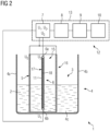
- the 1 , 2 each show a schematic representation of a device 1 for the capacitive measurement of a filling level in a filling volume 3 that can be filled or has been filled with a filling medium 2 according to an exemplary embodiment.
- the filling volume 3 is formed by the geometric-constructive dimensions of a container 4, ie in particular by the walls or wall sections 4a-4c of the container 4.
- the filling medium 2 is a liquid, i. H. e.g. B. a fuel.
- the container 4 is therefore, for example, a tank.
- the walls of the container 4 are denoted by 4a-4c.
- the device 1 comprises two measuring elements 5, 6, which are described in more detail below.
- a first measuring element 5 which can also be designated or considered as the first measuring electrode, is formed by a wall of a housing structure 14 of the device 1 , for example.
- the first measuring element 5 is electrically conductive or has electrically conductive properties; the first measuring element 5 is therefore made of an electrically conductive material, such as. B. metal formed.
- the potential of the first measuring element 5 is denoted by U 0 .
- the second measuring element 6 is accordingly received in or within a receiving space 15 formed by the housing structure 14 of the device 1 .
- the two measuring elements 5, 6 are each elongated and arranged in parallel, i. H. the respective longitudinal axes (not labeled) of the two measuring elements 5, 6 are aligned in parallel.
- the two measuring elements 5, 6 are arranged adjacent to one another such that the two measuring elements 5, 6 form a capacitor arrangement 16 or a capacitor.
- the first measuring element 5 forms a first electrode of the capacitor arrangement 16
- the second measuring element 6 forms a second electrode of the capacitor arrangement 16
- Filling level ie depending on the filling level, can be filled or filled with the filling medium 2 .
- the two measuring elements 5, 6 are arranged in the filling volume 3 or, depending on the filling level, are at least partially immersed in the filling medium 2.
- the second measuring element 6 is (significantly) less electrically conductive or, in contrast to the first measuring element 5, has (significantly) lower electrically conductive properties.
- the second measuring element 6 is therefore formed from a (significantly) less electrically conductive material or a (significantly) less electrically conductive material structure in contrast to or in comparison to the first measuring element 5 .
- the second measuring element 6, as in the 1 , 2 shown, have an (optional) insulating coating 17 or be surrounded by such.
- the insulating coating 17 can be omitted if the filling medium 2 is not electrically conductive; the insulating coating 17 is therefore basically optional.
- the second measuring element 6 is designed in such a way that a potential gradient, i. H. a gradient of an electric potential, between a first portion 6a of the second measuring element 6, i. H. in particular a first free end of the second measuring element 6, and a second portion 6b of the second measuring element 6, d. H. in particular a second free end of the second measuring element 6 opposite the first free end of the second measuring element 6 .
- the first section 6a of the second measuring element 6 is formed in the region of the first free end of the second measuring element 6 or by the first free end of the second measuring element 6 .
- the second section 6b of the second measuring element 6 is formed in the exemplary embodiment shown in the figure in the area of the second free end of the second measuring element 6 or by the second free end of the second measuring element 6 .
- the potential gradient that forms between said sections 6a, 6b of the second measuring element 6 is typically independent of the fill level of the filling medium 2.
- the measuring range of the second measuring element 6 extends between the two sections 6a, 6b.
- the second measuring element 6 is designed as a measuring resistor.
- the formation of the potential gradient between said sections 6a, 6b of the second measuring element 6 is based on the fact that the second measuring element 6 is designed as a measuring resistor.
- the resistance (value) of the measuring resistor is so large that a corresponding potential gradient forms between said sections 6a, 6b of the second measuring element 6.
- the measuring resistor can be, in particular on a substrate element 18, ie, for example, a printed circuit board, of the second measuring element 6 along the longitudinal axis of the second Measuring element 6 can be configured or configured to extend continuously.
- An equivalent circuit diagram for the first measuring element 5 and a second measuring element 6 designed accordingly as a measuring resistor or resistance element represents an RC chain with an "infinite" number of RC elements.
- the measuring resistor may be formed by a plurality of discrete electrically conductive, in particular metallic, surface elements Fi - F n arranged or formed along the longitudinal axis of the second measuring element 6 on a corresponding substrate element 18 of the second measuring element 6 and which are each connected to one another with discrete resistance elements R 1 - R n .
- An equivalent circuit diagram for a first measuring element 5 and a correspondingly designed second measuring element 6 represents a large number of discrete capacitive surfaces which are connected via electrical resistances.
- the measuring resistor and thus the second measuring element 6 can be formed, regardless of the specific embodiment, by at least partially, optionally completely, coating the substrate element 18 with a suitable material, ie for example a metal.
- the coating 11 can extend (in the longitudinal direction of the second measuring element) uninterruptedly or intermittently between said sections 6a, 6b of the second measuring element 6.
- the coating 11 can be realized by various, in particular chemical and/or physical, deposition or application or coating techniques, which enable a material application forming a coating 11 .
- the coating 11 forming the measuring resistor is applied to the substrate element 18 by way of example using a printing technique, in particular a screen printing technique.
- the exemplary embodiment shown has the second measuring element 6, in addition, an insulating coating 17 which forms electrical insulation of the second measuring element 6 and is made of a suitable insulating material. B. act on a plastic. The second measuring element 6 is isolated from the filling medium 2 in this way; i.e. there is no electrical contact between the filling medium 2 and the second measuring element 6.
- the device 1 also includes a voltage generating device 7 assigned to the second measuring element 6, ie in particular electrically connected to the second measuring element 6.
- the voltage generating device 7 is set up to provide or to generate a first electrical voltage U 1 and a second electrical voltage U 2 and to apply to the second measuring element 6.
- the Voltage generating device 7 with an internal or external voltage (supply) source (not shown), ie, for example, be connected to a power supply network.
- the first electrical voltage U 1 can be equal to the second electrical voltage U 2 .
- the first electrical voltage U 1 can also be different (in terms of absolute value) from the second electrical voltage U 2 , or vice versa; consequently, the voltage generating device 7 can optionally be set up to generate at least two identical or different electrical voltages U 1 , U 2 .
- the second measuring element 6 comprises separate voltage application areas, ie electrical contacts, to which the electrical voltages U 1 , U 2 provided or generated by the voltage generating device 7 can be applied or are created.
- a first voltage application area is formed through or in the area of the aforesaid first portion 6a of the second measuring element 6
- a second voltage application area is arranged or in the area of the aforesaid second portion 6b of the second measuring element 6 .
- the electrical voltages U 1 , U 2 provided or generated by the voltage generating device 7 can each be provided or generated in the form of a voltage pulse defined in particular in terms of amount and time; the voltage generating device 7 can accordingly be set up to provide or generate defined voltage pulses.
- the appropriately set up voltage generating device 7 can, for. B. be designed as a pulse generator.
- a first voltage pulse can be equal to a second voltage pulse.
- a first electrical voltage pulse can also be different (in terms of magnitude) from a second electrical voltage pulse, or vice versa; consequently, the voltage generating device 7 can optionally be set up to generate at least two identical or different electrical voltage pulses.
- the device 1 further comprises a control device 8 implemented in hardware and/or software and assigned to the voltage generating device 7.
- the control device 8 is set up to control the operation of the voltage generating device 7 in such a way that the first and second electrical voltage U 1 , U 2 alternately or is alternately applied to the second sensing element 6, that is, the first and second voltage application portions of the second sensing element 6.
- FIG. An alternating or alternating application or application of the first and second electrical voltage U 1 , U 2 to the second measuring element 6, ie to respective voltage application areas of the second measuring element 6, is to be understood in particular electrical voltages U 1 , U 2 or voltage pulses defined in terms of absolute value are applied alternately or alternately to respective voltage application areas of the second measuring element 6 .
- first voltage U 1 is applied to the first voltage application area of the second measuring element 6, while the second voltage U 2 is applied to the second voltage application area of the second measuring element 6, or - as in FIG 2 shown - the second voltage U 2 to the first voltage application area of the second measuring element 6, while the first voltage U 1 to the second voltage application area of the second measuring element 6 is present.
- the control device 8 is therefore set up to control the operation of the voltage generating device 7 in such a way that the first electrical voltage U 1 and the second electrical voltage U 2 are applied alternately to the second measuring element 6, ie to the respective voltage application areas of the second measuring element 6 . Accordingly, in the first voltage application area of the second measuring element 6 there is a first time interval (cf. 1 ) the first electrical voltage U 1 and in a subsequent second time interval (cf. 2 ) the second electrical voltage U 2 while at the second voltage application area of the second measuring element 6 in the first time interval (cf. 1 ) the second electrical voltage U 2 and in the subsequent second time interval (cf. 2 ) the first electrical voltage U 1 is applied. In a subsequent third time interval, the first electrical voltage U 1 is again present in the first voltage application area of the second measuring element 6, while the second electrical voltage U 2 is again present in the second voltage application area of the second measuring element 6 , and so on.
- the principle for capacitive filling level measurement that can be implemented with the device 1 is based in particular on a detection and evaluation of the electrical charge or electrical capacitance between the first and the second measuring element 5, 6, which varies depending on the filling level of the filling medium 2, via which the filling level of the filling medium 2 and this can therefore be determined.
- the second measuring element 6 typically serves as a level-independent voltage divider, which generates a potential gradient along the second measuring element 6 or along the measuring range of the second measuring element 6 .
- the level-independent voltage division along the second measuring element 6 or along the measuring range of the second measuring element 6 results in a level-dependent weighting of the electrical charge or capacitance between the first and the second measuring element 5, 6.
- the electrical charge between the first and the second measuring element 5 , 6 is therefore particularly dependent on the fill level of the filling medium 2, the potential along the potential gradient and the permittivity of the Filling medium 2, which, however, is not relevant to the determination of the fill level that can be realized by means of the device 1 and is therefore negligible.
- the determination of the filling level, which can be realized by means of the device 1 is therefore possible independently of the permittivity of the filling medium 2 .
- the device 1 further comprises a measuring device 9 implemented in hardware and/or software.
- the measuring device 9 is for measuring the possibly changing electrical charge or electrical capacitance between the first and second measuring element 5, 6 during the alternating or alternating application or when the first and second electrical voltages U 1 , U 2 are applied to the voltage application areas of the second measuring element 6 .
- the measuring device 9 is therefore set up to transfer a first electrical charge between the first and second measuring element 5, 6 while the first electrical voltage U 1 is applied to the first voltage application area of the second measuring element 6 and the second electrical voltage U 2 is applied to the second voltage application area of the second measuring element 6 and a second electrical charge between the first and second measuring element 5, 6 during the application of the second electrical voltage U 2 to the first voltage application area of the second measuring element 6 and the application of the first electrical voltage U 1 to the second voltage application area of the second measuring element 6 to measure.
- the measuring device 9 is also set up to describe the measured charge between the first and the second measuring element 5, 6 during the alternating application or application of the first and second electrical voltage U 1 , U 2 to the voltage application areas of the second measuring element 6 to generate a measurement signal.
- the measurement signal can contain at least two partial signals, with a first partial signal representing the electrical charge between the first and second measuring element 5, 6 while the first electrical voltage U 1 is applied to the first voltage application area of the second measuring element 6 and the second electrical voltage U 2 is applied at the second voltage application area of the second measuring element 6, and a second partial signal describes the electrical charge between the first and second measuring element 5, 6 while the second electrical voltage U 2 is applied to the first voltage application area of the second measuring element 6 and the application of the first electrical voltage U 1 at the second voltage application area of the second measuring element 6 describes.
- An evaluation device 10 implemented in hardware and/or software is assigned to the measuring device 9 .
- the evaluation device 10 is for evaluating the measured charge during the alternating or alternating application or application of the first and second electrical voltage U1, U2 to the or to the second (n) measuring element 6, ie in particular respective voltage application areas of the second measuring element 6, or for evaluating said measurement signal with regard to the level of the filling medium 2 in the filling volume 3 set up.
- the evaluation device 10 can comprise suitable evaluation logic or suitable evaluation algorithms.
- a measuring assembly 12 for the capacitive measurement of a filling level of a filling medium 2 in a filling volume 3 that can be filled with a filling medium 2 is also shown.
- the measuring assembly 12 comprises the measuring element 6 forming the second measuring element 6 of the device 1, the voltage generating device 7 assigned to the second measuring element 6, the control device 8, the measuring device 9 and the evaluation device 10.
- the measuring assembly 12 can be - as indicated by the box 13 shown in dashed lines - combined structurally to form a separately manageable assembly, d. H. e.g. B. on or in a housing body (not shown) of the measuring assembly 12 can be arranged or formed.
- the first measuring element 5 and the second measuring element 6 are each plate-like or plate-shaped.
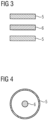
- a cross-sectional view of the measuring elements 5, 6 and their arrangement is shown in 3 , which shows a schematic representation of an exemplary embodiment of a corresponding capacitor arrangement 16. This in 3 lower first measuring element 5 is drawn in dashed lines because it is optional.
- first and second measuring elements 5, 6 or capacitor arrangements 16 formed by them are shown: 4 shows again in a cross-sectional view z. B. a coaxial arrangement of the measuring elements 5, 6.
- the coaxial arrangement of the measuring elements 5, 6 results from a tubular or -shaped design of the first measuring element 5 and a rod-like or -shaped design of the second measuring element 6.
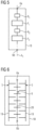
- FIG. 5 shows in a purely schematic basic representation the formation of the second measuring element 6 by several discrete, along the longitudinal axis A1 of the second measuring element 6 arranged or formed on a corresponding substrate element 18 of the second measuring element 6 electrically conductive, in particular metallic, surface elements F 1 - F n , each connected to discrete resistive elements R 1 - R n .
- an alternating arrangement of corresponding surface elements F 1 -F n and resistance elements R 1 -R n results.
- the second measuring element 6 can also be segmented, ie can comprise several measuring element segments forming the second measuring element 6, namely in the form of corresponding surface elements F 1 -F n and resistance elements R 1 -R n .
- the exemplary embodiment shown which shows a top view of a capacitor arrangement 16, shows that the measuring elements 5, 6 can also be formed by certain more or less electrically conductive structures on a substrate element 18, such as a printed circuit board. Electrically conductive structures (first electrically conductive structures 19) with a higher electrical conductivity form the first measuring element 5, electrically conductive structures (second electrically conductive structures 20) with a comparatively (significantly) lower electrical conductivity form the second measuring element 6.
- first electrically conductive structures 19 with a higher electrical conductivity form the first measuring element 5
- electrically conductive structures (second electrically conductive structures 20) with a comparatively (significantly) lower electrical conductivity form the second measuring element 6.
- the respective first and second electrically conductive structures 19, 20 are therefore arranged offset in parallel relative to one another in such a way that they interlock like fingers.
- the arrangement of the respective first and second electrically conductive structures 19, 20 is selected such that the respective first electrically conductive structures 19 are arranged or formed at least partially in intermediate spaces formed between two (immediate
- a method for the capacitive measurement of a filling level of a filling medium 2 in a filling volume 3 that can be filled or is filled with a filling medium 2 can be implemented.
Landscapes
- Physics & Mathematics (AREA)
- Engineering & Computer Science (AREA)
- Power Engineering (AREA)
- Thermal Sciences (AREA)
- Fluid Mechanics (AREA)
- General Physics & Mathematics (AREA)
- Electromagnetism (AREA)
- Measurement Of Levels Of Liquids Or Fluent Solid Materials (AREA)
- Measurement Of Length, Angles, Or The Like Using Electric Or Magnetic Means (AREA)
- Automatic Analysis And Handling Materials Therefor (AREA)
- Dry Development In Electrophotography (AREA)
Applications Claiming Priority (2)
| Application Number | Priority Date | Filing Date | Title |
|---|---|---|---|
| DE102017127145.7A DE102017127145B4 (de) | 2017-11-17 | 2017-11-17 | Vorrichtung und Verfahren zur kapazitiven Messung eines Füllstands eines Füllmediums |
| PCT/EP2018/077360 WO2019096493A1 (de) | 2017-11-17 | 2018-10-08 | Vorrichtung und verfahren zur kapazitiven messung eines füllstands eines füllmediums |
Publications (2)
| Publication Number | Publication Date |
|---|---|
| EP3665447A1 EP3665447A1 (de) | 2020-06-17 |
| EP3665447B1 true EP3665447B1 (de) | 2023-05-24 |
Family
ID=63794516
Family Applications (1)
| Application Number | Title | Priority Date | Filing Date |
|---|---|---|---|
| EP18783010.4A Active EP3665447B1 (de) | 2017-11-17 | 2018-10-08 | Vorrichtung und verfahren zur kapazitiven messung eines füllstands eines füllmediums |
Country Status (14)
| Country | Link |
|---|---|
| US (1) | US11428565B2 (pl) |
| EP (1) | EP3665447B1 (pl) |
| JP (1) | JP6931132B2 (pl) |
| KR (1) | KR102380219B1 (pl) |
| CN (1) | CN111247400B (pl) |
| AU (1) | AU2018369390B2 (pl) |
| CA (1) | CA3078649C (pl) |
| DE (1) | DE102017127145B4 (pl) |
| ES (1) | ES2953104T3 (pl) |
| FI (1) | FI3665447T3 (pl) |
| PL (1) | PL3665447T3 (pl) |
| RU (1) | RU2743069C1 (pl) |
| WO (1) | WO2019096493A1 (pl) |
| ZA (1) | ZA202002230B (pl) |
Family Cites Families (33)
| Publication number | Priority date | Publication date | Assignee | Title |
|---|---|---|---|---|
| US3901079A (en) * | 1974-06-18 | 1975-08-26 | Agridustrial Electronics | Two-mode capacitive liquid level sensing system |
| DE3127637C2 (de) * | 1980-08-01 | 1988-08-18 | Endress U. Hauser Gmbh U. Co, 7867 Maulburg | Anordnung zur Feststellung des Füllstands in einem Behälter |
| GB2117520B (en) * | 1982-03-29 | 1985-07-03 | Smiths Industries Plc | Fuel gauging system |
| SU1290078A1 (ru) * | 1984-05-28 | 1987-02-15 | Всесоюзный научно-исследовательский институт синтетических волокон | Датчик контрол границы раздела фаз |
| JPS61233322A (ja) * | 1985-04-08 | 1986-10-17 | Kobe Steel Ltd | 液体ヘリウムのレベル計測方法及び液体ヘリウムレベル計 |
| JP2839328B2 (ja) * | 1990-04-10 | 1998-12-16 | 矢崎総業株式会社 | 放熱式レベルセンサー |
| JP2839349B2 (ja) * | 1990-10-12 | 1998-12-16 | 矢崎総業株式会社 | 放熱式レベルセンサーの液体のレベル測定方式 |
| US5461321A (en) * | 1993-09-17 | 1995-10-24 | Penberthy, Inc. | Apparatus and method for measuring capacitance from the duration of a charge-discharge charge cycle |
| JP3025837B2 (ja) * | 1995-11-22 | 2000-03-27 | 日本航空電子工業株式会社 | 静電容量計測装置 |
| JP3378722B2 (ja) * | 1996-03-11 | 2003-02-17 | セイコープレシジョン株式会社 | 静電容量型センサ |
| US5747689A (en) * | 1996-12-09 | 1998-05-05 | Ford Global Technologies, Inc. | Fluid level sensing system |
| US6212956B1 (en) * | 1998-12-23 | 2001-04-10 | Agilent Technologies, Inc. | High output capacitative gas/liquid detector |
| DE19916979A1 (de) * | 1999-04-15 | 2000-11-02 | Sican Gmbh | Verfahren zur Füllstandsmessung und Füllstandssensor |
| RU2166736C2 (ru) * | 1999-06-01 | 2001-05-10 | Военный автомобильный институт | Емкостный компенсационный уровнемер |
| EP1274972B1 (en) * | 2000-04-14 | 2005-07-06 | Robertshaw Controls Company | Capacitance level measurement circuit and system |
| DE10161069A1 (de) * | 2001-12-12 | 2003-06-18 | Endress & Hauser Gmbh & Co Kg | Feldgeräteelektronik mit einer Sensoreinheit für kapazitive Füllstandsmessungen in einem Behälter |
| US7038467B2 (en) * | 2004-03-04 | 2006-05-02 | Delphi Technologies, Inc. | Resonant network fluid level sensor assembly |
| US7107838B2 (en) * | 2004-04-19 | 2006-09-19 | Fook Tin Technologies Ltd. | Apparatus and methods for monitoring water consumption and filter usage |
| US7219545B2 (en) * | 2004-07-28 | 2007-05-22 | Vertex Pharmaceuticals, Inc. | Sensor for levels of conductive liquids |
| DE102005032131A1 (de) * | 2005-07-07 | 2007-01-18 | Endress + Hauser Gmbh + Co. Kg | Vorrichtung zur kapazitiven Bestimmung und/oder Überwachung des Füllstandes |
| EP1992921B1 (de) * | 2007-05-16 | 2011-08-10 | FAFNIR GmbH | Verfahren und Vorrichtung zur Füllstandbestimmung |
| US20100295565A1 (en) * | 2008-01-09 | 2010-11-25 | Diraction, Llc | Automated phase separation and fuel quality sensor |
| IT1394449B1 (it) * | 2009-05-26 | 2012-06-15 | Eltek Spa | Sensore di livello e relativo circuito di controllo, in particolare per un filtro di veicoli |
| CN102193033B (zh) * | 2010-03-08 | 2015-02-18 | 上海海栎创微电子有限公司 | 一种具有快速响应的自电容变化测量电路 |
| DE102010025118A1 (de) * | 2010-06-25 | 2011-12-29 | Siemens Healthcare Diagnostics Products Gmbh | Berührungslose Füllstandsmessung von Flüssigkeiten |
| US8590375B2 (en) | 2011-03-22 | 2013-11-26 | Rochester Gauges, Inc. | Self-calibrating capacitive liquid level sensor assembly and method |
| US20160051176A1 (en) * | 2013-03-15 | 2016-02-25 | C.R. Bard, Inc. | Urine Monitoring Systems and Methods |
| JP2014232002A (ja) * | 2013-05-28 | 2014-12-11 | 愛三工業株式会社 | 液質検出装置 |
| CN103557904B (zh) * | 2013-10-12 | 2016-08-24 | 珠海市长陆工业自动控制系统有限公司 | 电位尺连续料位测量系统及方法 |
| CN107110690A (zh) * | 2014-09-15 | 2017-08-29 | 埃尔特克有限公司 | 用于检测介质的水平的传感器 |
| US10077999B2 (en) * | 2015-07-14 | 2018-09-18 | Cytochip Inc. | Volume sensing in fluidic cartridge |
| FR3043198B1 (fr) * | 2015-11-04 | 2017-12-22 | Dover Europe Sarl | Dispositif de mesure de niveau dans un reservoir |
| ITUA20163239A1 (it) * | 2016-04-18 | 2017-10-18 | Eltek Spa | Dispositivo per la rilevazione del livello di un mezzo |
-
2017
- 2017-11-17 DE DE102017127145.7A patent/DE102017127145B4/de active Active
-
2018
- 2018-10-08 AU AU2018369390A patent/AU2018369390B2/en active Active
- 2018-10-08 PL PL18783010.4T patent/PL3665447T3/pl unknown
- 2018-10-08 FI FIEP18783010.4T patent/FI3665447T3/en active
- 2018-10-08 ES ES18783010T patent/ES2953104T3/es active Active
- 2018-10-08 US US16/754,052 patent/US11428565B2/en active Active
- 2018-10-08 KR KR1020207013160A patent/KR102380219B1/ko active Active
- 2018-10-08 WO PCT/EP2018/077360 patent/WO2019096493A1/de not_active Ceased
- 2018-10-08 JP JP2020541857A patent/JP6931132B2/ja active Active
- 2018-10-08 CA CA3078649A patent/CA3078649C/en active Active
- 2018-10-08 RU RU2020115097A patent/RU2743069C1/ru active
- 2018-10-08 CN CN201880068166.3A patent/CN111247400B/zh active Active
- 2018-10-08 EP EP18783010.4A patent/EP3665447B1/de active Active
-
2020
- 2020-05-04 ZA ZA2020/02230A patent/ZA202002230B/en unknown
Also Published As
| Publication number | Publication date |
|---|---|
| AU2018369390B2 (en) | 2021-06-03 |
| PL3665447T3 (pl) | 2023-08-14 |
| JP6931132B2 (ja) | 2021-09-01 |
| DE102017127145B4 (de) | 2021-03-04 |
| CA3078649C (en) | 2023-08-01 |
| US20210372841A1 (en) | 2021-12-02 |
| RU2743069C1 (ru) | 2021-02-15 |
| CN111247400B (zh) | 2022-04-08 |
| AU2018369390A1 (en) | 2020-05-28 |
| EP3665447A1 (de) | 2020-06-17 |
| DE102017127145A1 (de) | 2019-05-23 |
| KR102380219B1 (ko) | 2022-03-29 |
| ZA202002230B (en) | 2021-06-30 |
| FI3665447T3 (en) | 2023-07-21 |
| CA3078649A1 (en) | 2019-05-23 |
| CN111247400A (zh) | 2020-06-05 |
| ES2953104T3 (es) | 2023-11-08 |
| KR20200062315A (ko) | 2020-06-03 |
| JP2020537164A (ja) | 2020-12-17 |
| WO2019096493A1 (de) | 2019-05-23 |
| US11428565B2 (en) | 2022-08-30 |
Similar Documents
| Publication | Publication Date | Title |
|---|---|---|
| DE2842028C3 (de) | Vorrichtung zum Messen der Kapazität eines Kondensators | |
| DE3843243C2 (de) | Vorrichtung zur Feststellung des Alkoholgehaltes von Kraftstoffen | |
| EP3152530B1 (de) | Verfahren und vorrichtung zur überwachung des füllstandes eines mediums in einem behälter | |
| DE2755517A1 (de) | Kapazitive vorrichtung zur messung eines fluessigkeitspegels | |
| EP2759812B1 (de) | Verfahren und Vorrichtung zur kapazitiven Füllstandsmessung von Flüssigkeiten oder Schüttgütern | |
| DE10261767A1 (de) | Vorrichtung und Verfahren zur Kapazitätsmessung sowie Einrichtung zum Ermitteln des Füllstandes einer Flüssigkeit mit einer solchen Vorrichtung | |
| DE102010030362A1 (de) | Vorrichtung und Verfahren zur kapazitiven Bestimmung eines Füllstandes einer Flüssigkeit in einem Behälter | |
| DE102010060465A1 (de) | Verfahren zur Kalibrierung einer Leitfähigkeitsmesszelle | |
| WO2019011595A1 (de) | Kapazitives messverfahren und füllstandsmessgerät | |
| EP1947429B1 (de) | Verfahren zur Bedienung einer Vorrichtung zur kapazitiven Bestimmung und/oder Überwachung einer Prozessgröße | |
| EP4134637B1 (de) | Kapazitive füllstandsonde ohne totbereich | |
| EP2092279B1 (de) | Vorrichtung zur bestimmung und/oder überwachung einer prozessgrösse | |
| DE102016109102B3 (de) | Kapazitiver Sensor und Verfahren zur Bestimmung der Permittivitätsverteilung in einem Objekt | |
| DE102017012240B4 (de) | Vorrichtung und Verfahren zur kapazitiven Messung eines Füllstands eines Füllmediums | |
| DE102017127145B4 (de) | Vorrichtung und Verfahren zur kapazitiven Messung eines Füllstands eines Füllmediums | |
| DE9204374U1 (de) | Vorrichtung zur Messung von Mehrphasenströmungen charakterisierenden Parametern | |
| DE102023100873A1 (de) | Drucksensor | |
| DE29805413U1 (de) | Füllstandsgeber | |
| EP2735851B1 (de) | Verfahren und Vorrichtung zur kapazitiven Füllstandsmessung mit Kabelsonde oder Stabsonde | |
| DE102017200414A1 (de) | Messgerät für die Prozess- und Automatisierungstechnik | |
| WO2004008084A1 (de) | Verfahren zur messung des füllstandes eines fluids in einem behälter und entsprechender füllstandssensor mit wenigstens einem kapazitiven sensorelement | |
| DE3902107A1 (de) | Kapazitive fuellstands- und niveaumesseinrichtung | |
| EP4211434B1 (de) | Dreidimensionaler schaltungsträger, anordnung aus einem solchen schaltungsträger und einer metallischen hülse, messgerät der prozessmesstechnik mit einer solchen anordnung sowie verwendung einer solchen anordnung | |
| DE19502195A1 (de) | Verfahren und Anordnung zur Auswertung der Signale eines kapazitiven Füllstandsensors | |
| DE102021204556A1 (de) | Verfahren und Vorrichtung zum Überwachen einer Messposition hinsichtlich einer Präsenz, Menge und/oder Art einer an der Messposition auftretenden Chemikalie |
Legal Events
| Date | Code | Title | Description |
|---|---|---|---|
| STAA | Information on the status of an ep patent application or granted ep patent |
Free format text: STATUS: UNKNOWN |
|
| STAA | Information on the status of an ep patent application or granted ep patent |
Free format text: STATUS: THE INTERNATIONAL PUBLICATION HAS BEEN MADE |
|
| PUAI | Public reference made under article 153(3) epc to a published international application that has entered the european phase |
Free format text: ORIGINAL CODE: 0009012 |
|
| STAA | Information on the status of an ep patent application or granted ep patent |
Free format text: STATUS: REQUEST FOR EXAMINATION WAS MADE |
|
| 17P | Request for examination filed |
Effective date: 20200303 |
|
| AK | Designated contracting states |
Kind code of ref document: A1 Designated state(s): AL AT BE BG CH CY CZ DE DK EE ES FI FR GB GR HR HU IE IS IT LI LT LU LV MC MK MT NL NO PL PT RO RS SE SI SK SM TR |
|
| AX | Request for extension of the european patent |
Extension state: BA ME |
|
| DAV | Request for validation of the european patent (deleted) | ||
| DAX | Request for extension of the european patent (deleted) | ||
| STAA | Information on the status of an ep patent application or granted ep patent |
Free format text: STATUS: EXAMINATION IS IN PROGRESS |
|
| 17Q | First examination report despatched |
Effective date: 20221019 |
|
| GRAP | Despatch of communication of intention to grant a patent |
Free format text: ORIGINAL CODE: EPIDOSNIGR1 |
|
| STAA | Information on the status of an ep patent application or granted ep patent |
Free format text: STATUS: GRANT OF PATENT IS INTENDED |
|
| GRAS | Grant fee paid |
Free format text: ORIGINAL CODE: EPIDOSNIGR3 |
|
| INTG | Intention to grant announced |
Effective date: 20230316 |
|
| GRAA | (expected) grant |
Free format text: ORIGINAL CODE: 0009210 |
|
| STAA | Information on the status of an ep patent application or granted ep patent |
Free format text: STATUS: THE PATENT HAS BEEN GRANTED |
|
| AK | Designated contracting states |
Kind code of ref document: B1 Designated state(s): AL AT BE BG CH CY CZ DE DK EE ES FI FR GB GR HR HU IE IS IT LI LT LU LV MC MK MT NL NO PL PT RO RS SE SI SK SM TR |
|
| REG | Reference to a national code |
Ref country code: GB Ref legal event code: FG4D Free format text: NOT ENGLISH |
|
| REG | Reference to a national code |
Ref country code: CH Ref legal event code: EP |
|
| REG | Reference to a national code |
Ref country code: DE Ref legal event code: R096 Ref document number: 502018012195 Country of ref document: DE |
|
| REG | Reference to a national code |
Ref country code: AT Ref legal event code: REF Ref document number: 1569768 Country of ref document: AT Kind code of ref document: T Effective date: 20230615 |
|
| REG | Reference to a national code |
Ref country code: IE Ref legal event code: FG4D Free format text: LANGUAGE OF EP DOCUMENT: GERMAN |
|
| P01 | Opt-out of the competence of the unified patent court (upc) registered |
Effective date: 20230524 |
|
| REG | Reference to a national code |
Ref country code: FI Ref legal event code: FGE |
|
| REG | Reference to a national code |
Ref country code: SE Ref legal event code: TRGR |
|
| REG | Reference to a national code |
Ref country code: NL Ref legal event code: FP |
|
| REG | Reference to a national code |
Ref country code: LT Ref legal event code: MG9D |
|
| PG25 | Lapsed in a contracting state [announced via postgrant information from national office to epo] |
Ref country code: PT Free format text: LAPSE BECAUSE OF FAILURE TO SUBMIT A TRANSLATION OF THE DESCRIPTION OR TO PAY THE FEE WITHIN THE PRESCRIBED TIME-LIMIT Effective date: 20230925 Ref country code: NO Free format text: LAPSE BECAUSE OF FAILURE TO SUBMIT A TRANSLATION OF THE DESCRIPTION OR TO PAY THE FEE WITHIN THE PRESCRIBED TIME-LIMIT Effective date: 20230824 |
|
| REG | Reference to a national code |
Ref country code: ES Ref legal event code: FG2A Ref document number: 2953104 Country of ref document: ES Kind code of ref document: T3 Effective date: 20231108 |
|
| PG25 | Lapsed in a contracting state [announced via postgrant information from national office to epo] |
Ref country code: RS Free format text: LAPSE BECAUSE OF FAILURE TO SUBMIT A TRANSLATION OF THE DESCRIPTION OR TO PAY THE FEE WITHIN THE PRESCRIBED TIME-LIMIT Effective date: 20230524 Ref country code: LV Free format text: LAPSE BECAUSE OF FAILURE TO SUBMIT A TRANSLATION OF THE DESCRIPTION OR TO PAY THE FEE WITHIN THE PRESCRIBED TIME-LIMIT Effective date: 20230524 Ref country code: LT Free format text: LAPSE BECAUSE OF FAILURE TO SUBMIT A TRANSLATION OF THE DESCRIPTION OR TO PAY THE FEE WITHIN THE PRESCRIBED TIME-LIMIT Effective date: 20230524 Ref country code: IS Free format text: LAPSE BECAUSE OF FAILURE TO SUBMIT A TRANSLATION OF THE DESCRIPTION OR TO PAY THE FEE WITHIN THE PRESCRIBED TIME-LIMIT Effective date: 20230924 Ref country code: HR Free format text: LAPSE BECAUSE OF FAILURE TO SUBMIT A TRANSLATION OF THE DESCRIPTION OR TO PAY THE FEE WITHIN THE PRESCRIBED TIME-LIMIT Effective date: 20230524 Ref country code: GR Free format text: LAPSE BECAUSE OF FAILURE TO SUBMIT A TRANSLATION OF THE DESCRIPTION OR TO PAY THE FEE WITHIN THE PRESCRIBED TIME-LIMIT Effective date: 20230825 |
|
| PG25 | Lapsed in a contracting state [announced via postgrant information from national office to epo] |
Ref country code: SK Free format text: LAPSE BECAUSE OF FAILURE TO SUBMIT A TRANSLATION OF THE DESCRIPTION OR TO PAY THE FEE WITHIN THE PRESCRIBED TIME-LIMIT Effective date: 20230524 |
|
| PG25 | Lapsed in a contracting state [announced via postgrant information from national office to epo] |
Ref country code: SM Free format text: LAPSE BECAUSE OF FAILURE TO SUBMIT A TRANSLATION OF THE DESCRIPTION OR TO PAY THE FEE WITHIN THE PRESCRIBED TIME-LIMIT Effective date: 20230524 Ref country code: SK Free format text: LAPSE BECAUSE OF FAILURE TO SUBMIT A TRANSLATION OF THE DESCRIPTION OR TO PAY THE FEE WITHIN THE PRESCRIBED TIME-LIMIT Effective date: 20230524 Ref country code: RO Free format text: LAPSE BECAUSE OF FAILURE TO SUBMIT A TRANSLATION OF THE DESCRIPTION OR TO PAY THE FEE WITHIN THE PRESCRIBED TIME-LIMIT Effective date: 20230524 Ref country code: EE Free format text: LAPSE BECAUSE OF FAILURE TO SUBMIT A TRANSLATION OF THE DESCRIPTION OR TO PAY THE FEE WITHIN THE PRESCRIBED TIME-LIMIT Effective date: 20230524 Ref country code: DK Free format text: LAPSE BECAUSE OF FAILURE TO SUBMIT A TRANSLATION OF THE DESCRIPTION OR TO PAY THE FEE WITHIN THE PRESCRIBED TIME-LIMIT Effective date: 20230524 |
|
| REG | Reference to a national code |
Ref country code: DE Ref legal event code: R097 Ref document number: 502018012195 Country of ref document: DE |
|
| PLBE | No opposition filed within time limit |
Free format text: ORIGINAL CODE: 0009261 |
|
| STAA | Information on the status of an ep patent application or granted ep patent |
Free format text: STATUS: NO OPPOSITION FILED WITHIN TIME LIMIT |
|
| 26N | No opposition filed |
Effective date: 20240227 |
|
| PG25 | Lapsed in a contracting state [announced via postgrant information from national office to epo] |
Ref country code: SI Free format text: LAPSE BECAUSE OF FAILURE TO SUBMIT A TRANSLATION OF THE DESCRIPTION OR TO PAY THE FEE WITHIN THE PRESCRIBED TIME-LIMIT Effective date: 20230524 |
|
| PG25 | Lapsed in a contracting state [announced via postgrant information from national office to epo] |
Ref country code: SI Free format text: LAPSE BECAUSE OF FAILURE TO SUBMIT A TRANSLATION OF THE DESCRIPTION OR TO PAY THE FEE WITHIN THE PRESCRIBED TIME-LIMIT Effective date: 20230524 Ref country code: MC Free format text: LAPSE BECAUSE OF FAILURE TO SUBMIT A TRANSLATION OF THE DESCRIPTION OR TO PAY THE FEE WITHIN THE PRESCRIBED TIME-LIMIT Effective date: 20230524 |
|
| REG | Reference to a national code |
Ref country code: BE Ref legal event code: MM Effective date: 20231031 |
|
| PG25 | Lapsed in a contracting state [announced via postgrant information from national office to epo] |
Ref country code: LU Free format text: LAPSE BECAUSE OF NON-PAYMENT OF DUE FEES Effective date: 20231008 |
|
| PG25 | Lapsed in a contracting state [announced via postgrant information from national office to epo] |
Ref country code: LU Free format text: LAPSE BECAUSE OF NON-PAYMENT OF DUE FEES Effective date: 20231008 |
|
| PG25 | Lapsed in a contracting state [announced via postgrant information from national office to epo] |
Ref country code: BE Free format text: LAPSE BECAUSE OF NON-PAYMENT OF DUE FEES Effective date: 20231031 |
|
| PG25 | Lapsed in a contracting state [announced via postgrant information from national office to epo] |
Ref country code: IE Free format text: LAPSE BECAUSE OF NON-PAYMENT OF DUE FEES Effective date: 20231008 |
|
| PG25 | Lapsed in a contracting state [announced via postgrant information from national office to epo] |
Ref country code: IE Free format text: LAPSE BECAUSE OF NON-PAYMENT OF DUE FEES Effective date: 20231008 |
|
| PG25 | Lapsed in a contracting state [announced via postgrant information from national office to epo] |
Ref country code: BG Free format text: LAPSE BECAUSE OF FAILURE TO SUBMIT A TRANSLATION OF THE DESCRIPTION OR TO PAY THE FEE WITHIN THE PRESCRIBED TIME-LIMIT Effective date: 20230524 |
|
| PG25 | Lapsed in a contracting state [announced via postgrant information from national office to epo] |
Ref country code: BG Free format text: LAPSE BECAUSE OF FAILURE TO SUBMIT A TRANSLATION OF THE DESCRIPTION OR TO PAY THE FEE WITHIN THE PRESCRIBED TIME-LIMIT Effective date: 20230524 |
|
| PG25 | Lapsed in a contracting state [announced via postgrant information from national office to epo] |
Ref country code: CY Free format text: LAPSE BECAUSE OF FAILURE TO SUBMIT A TRANSLATION OF THE DESCRIPTION OR TO PAY THE FEE WITHIN THE PRESCRIBED TIME-LIMIT; INVALID AB INITIO Effective date: 20181008 |
|
| PG25 | Lapsed in a contracting state [announced via postgrant information from national office to epo] |
Ref country code: HU Free format text: LAPSE BECAUSE OF FAILURE TO SUBMIT A TRANSLATION OF THE DESCRIPTION OR TO PAY THE FEE WITHIN THE PRESCRIBED TIME-LIMIT; INVALID AB INITIO Effective date: 20181008 |
|
| PGFP | Annual fee paid to national office [announced via postgrant information from national office to epo] |
Ref country code: PL Payment date: 20250925 Year of fee payment: 8 Ref country code: TR Payment date: 20250930 Year of fee payment: 8 |
|
| PGFP | Annual fee paid to national office [announced via postgrant information from national office to epo] |
Ref country code: CZ Payment date: 20250925 Year of fee payment: 8 |
|
| REG | Reference to a national code |
Ref country code: CH Ref legal event code: U11 Free format text: ST27 STATUS EVENT CODE: U-0-0-U10-U11 (AS PROVIDED BY THE NATIONAL OFFICE) Effective date: 20251101 |
|
| PGFP | Annual fee paid to national office [announced via postgrant information from national office to epo] |
Ref country code: NL Payment date: 20251023 Year of fee payment: 8 |
|
| PGFP | Annual fee paid to national office [announced via postgrant information from national office to epo] |
Ref country code: DE Payment date: 20251029 Year of fee payment: 8 |
|
| PGFP | Annual fee paid to national office [announced via postgrant information from national office to epo] |
Ref country code: GB Payment date: 20251024 Year of fee payment: 8 |
|
| PGFP | Annual fee paid to national office [announced via postgrant information from national office to epo] |
Ref country code: AT Payment date: 20251021 Year of fee payment: 8 |
|
| PGFP | Annual fee paid to national office [announced via postgrant information from national office to epo] |
Ref country code: FI Payment date: 20251022 Year of fee payment: 8 Ref country code: IT Payment date: 20251031 Year of fee payment: 8 |
|
| PGFP | Annual fee paid to national office [announced via postgrant information from national office to epo] |
Ref country code: FR Payment date: 20251029 Year of fee payment: 8 |
|
| PGFP | Annual fee paid to national office [announced via postgrant information from national office to epo] |
Ref country code: CH Payment date: 20251101 Year of fee payment: 8 Ref country code: SE Payment date: 20251023 Year of fee payment: 8 |
|
| PGFP | Annual fee paid to national office [announced via postgrant information from national office to epo] |
Ref country code: ES Payment date: 20251114 Year of fee payment: 8 |