EP3665443B1 - Durchflussmesser und messkanal - Google Patents
Durchflussmesser und messkanal Download PDFInfo
- Publication number
- EP3665443B1 EP3665443B1 EP18752149.7A EP18752149A EP3665443B1 EP 3665443 B1 EP3665443 B1 EP 3665443B1 EP 18752149 A EP18752149 A EP 18752149A EP 3665443 B1 EP3665443 B1 EP 3665443B1
- Authority
- EP
- European Patent Office
- Prior art keywords
- measuring channel
- flow meter
- measuring
- meter according
- profile
- Prior art date
- Legal status (The legal status is an assumption and is not a legal conclusion. Google has not performed a legal analysis and makes no representation as to the accuracy of the status listed.)
- Active
Links
Images

Classifications
-
- G—PHYSICS
- G01—MEASURING; TESTING
- G01F—MEASURING VOLUME, VOLUME FLOW, MASS FLOW OR LIQUID LEVEL; METERING BY VOLUME
- G01F1/00—Measuring the volume flow or mass flow of fluid or fluent solid material wherein the fluid passes through a meter in a continuous flow
- G01F1/66—Measuring the volume flow or mass flow of fluid or fluent solid material wherein the fluid passes through a meter in a continuous flow by measuring frequency, phase shift or propagation time of electromagnetic or other waves, e.g. using ultrasonic flowmeters
-
- G—PHYSICS
- G01—MEASURING; TESTING
- G01F—MEASURING VOLUME, VOLUME FLOW, MASS FLOW OR LIQUID LEVEL; METERING BY VOLUME
- G01F1/00—Measuring the volume flow or mass flow of fluid or fluent solid material wherein the fluid passes through a meter in a continuous flow
- G01F1/66—Measuring the volume flow or mass flow of fluid or fluent solid material wherein the fluid passes through a meter in a continuous flow by measuring frequency, phase shift or propagation time of electromagnetic or other waves, e.g. using ultrasonic flowmeters
- G01F1/662—Constructional details
-
- G—PHYSICS
- G01—MEASURING; TESTING
- G01F—MEASURING VOLUME, VOLUME FLOW, MASS FLOW OR LIQUID LEVEL; METERING BY VOLUME
- G01F1/00—Measuring the volume flow or mass flow of fluid or fluent solid material wherein the fluid passes through a meter in a continuous flow
- G01F1/76—Devices for measuring mass flow of a fluid or a fluent solid material
- G01F1/78—Direct mass flowmeters
- G01F1/80—Direct mass flowmeters operating by measuring pressure, force, momentum, or frequency of a fluid flow to which a rotational movement has been imparted
- G01F1/84—Coriolis or gyroscopic mass flowmeters
-
- G—PHYSICS
- G01—MEASURING; TESTING
- G01F—MEASURING VOLUME, VOLUME FLOW, MASS FLOW OR LIQUID LEVEL; METERING BY VOLUME
- G01F15/00—Details of, or accessories for, apparatus of groups G01F1/00 - G01F13/00 insofar as such details or appliances are not adapted to particular types of such apparatus
Definitions
- the invention relates to a flow meter for measuring the flow of fluids in a pipeline or the like according to the preamble of patent claim 1, and a suitable measuring channel.
- EP 2 306 160 A1 discloses a flow meter/flow meter in which the measuring insert accommodates both the ultrasonic converter and forms the actual measuring channel.
- the flow guidance within the measuring channel is determined by a housing insert which can be inserted from the end face of the housing and which also carries reflectors for the ultrasonic signals, so that the ultrasound is emitted by one of the ultrasonic transducers and transmitted via the reflectors to the other, for example downstream ultrasonic transducer is reflected.
- the signal can also be routed in the opposite direction.
- a disadvantage of such solutions is that the measuring channel consists of materials that require a great deal of effort in the manufacturing process.
- the pamphlet U.S. 9,689,727 B2 shows an ultrasonic flowmeter with a measuring tube, the basic cross-section of which is manufactured by applying internal high pressure, i.e. by means of hydroforming. After the hydroforming, a flow drilling process is used to create recesses in the wall of the measuring tube, in which recesses ultrasonic sensors are inserted.
- the measuring tube has a larger nominal diameter in the area of its inlet and outlet than in the area of the recesses or the sensors used.
- inwardly curved reflection zones are formed as a result of the hydroforming.
- This configuration is in accordance with U.S. 9,689,727 B2 achieved by expanding the complete measuring tube during hydroforming.
- the nominal diameter of the starting material is chosen so small that the inward-facing reflective surfaces can remain.
- the invention is based on the object of creating a flow meter/flow counter and a measuring channel that can be produced with little effort in terms of production and process technology.
- the object is achieved according to the invention in that the measuring channel is produced by hydroforming.
- the hydroforming manufacturing process ensures that a relatively thin-walled measuring channel can be manufactured in one production step, regardless of the required size of the measuring channel.
- the manufacturing process can be used regardless of whether it is a measuring channel for a domestic water meter (from DN15) or a bulk water meter (up to DN300).
- Hydroforming is conceivable for measuring channels with a wide range of outer tube wall thicknesses.
- Various metallic materials as the starting material for the pipe allow a wide range of variants and do not require any post-processing.
- Another advantage compared to cast measuring channels is that a more finely structured surface layer is achieved, so that less turbulence can occur in the area of the measuring channel, which would impair the measuring accuracy.
- a hydroformed profile can be adapted to different conditions, whereby the same initial profile can always be used.
- the measuring channel has at least two recesses for accommodating a measuring device. These are spaced apart from one another in the direction of flow on one side of the measuring channel.
- the recesses can, for example, be in the form of elongated holes and can be introduced in the course of the hydroforming.
- the recesses for accommodating a measuring device are dispensed with, so that the sound can be heard through the wall of the measuring channel.
- a cross-sectional profile of the measuring channel is designed with a larger clear width along the direction of flow than transversely thereto.
- the tube diameter is brought into the shape described above.
- these are designed with a rounded design. This applies both to the area from the round tube to the cross-sectional profile mentioned above, as well as in the area of the transitions between the long and narrow side walls of the measuring channel.
- the hydroforming process makes it possible to shape the measuring channel in one step. Only a tube is required as a semi-finished product from which the measuring channel is made in one piece.
- the tube can be designed with a round cross section or with a rectangular or square cross section or in some other way. Both a variant with and without a flange can be implemented in one production step. According to the invention, it is preferred if the connection flanges are formed in a production step following the hydroforming.
- connection flange can be formed in each case by a type of flanging process on the measurement channel itself or by subsequent attachment, for example by welding, shrinking, or gluing of the separately manufactured connection flanges to the measurement channel.
- the measuring channel is formed in such a way that an approximately roof-shaped bulge preferably occurs on one side, the recesses for the sensors then being arranged in the region of two inclined walls of the bulge arranged obliquely to one another.
- the sensors are arranged in the area of the bulge.
- a particular advantage of this design is that the sensors are then arranged at an angle, so that the signals are coupled into and out of the measuring channel at a corresponding angle.
- the alignment of the sensors compared to a straight measuring channel without curvature is considerably easier.
- the approximately rectangular profile is arranged horizontally, so that the smaller width runs in the vertical direction (direction of gravity).
- a measuring channel for a flow meter is produced by hydroforming.
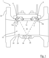
- figure 1 1 shows a longitudinal section of a flow meter 1.
- This representation shows two coupling pieces 2, 4 with two sensors 6 and 8, respectively. These are each inserted in two recesses 10a, 10b.
- the coupling surfaces 12 run flush with the peripheral wall (transverse wall 14 and adjacent areas of a side wall 16) of a measuring channel 18, which is formed by a piece of pipe 20 in this exemplary embodiment.
- a part of a flange 22 thus forms the transverse wall 14 .
- An opposite transverse wall 24 is formed in this embodiment with a pocket 26 open to the outside, in which a reflector 28 is inserted.
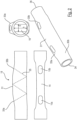
- FIG 2 a measuring channel 18, here without a flange, is shown, which was produced by hydroforming.
- the two recesses 10a, 10b can be clearly seen.
- Top right in figure 1 a cross section of the measuring channel is shown, from which it can be seen that in the flow area of the measuring channel 18 the clear height h is greater than the width b.
- the cross-sectional profile (top right) is shown such that the height h runs vertically (direction of gravity), so that the rectangular profile is arranged upright, so to speak. In field installation, however, it is preferred if the profile is installed "lying" so that the smaller width b is located in the vertical direction. This lying position of use offers the advantage that no accumulation of air can occur in the area of the recesses 10a, which would lead to an erroneous measurement.
- the transitions 30a in the area of the measuring channel and the transitions 30b in the transition area from the initial profile to the area of the measuring channel 18 are rounded.
- the raw part as the starting profile is a round profile for each measuring channel.
- All hydroformable materials are conceivable as materials, i.e. steel, stainless steel, special alloys, aluminum, copper, brass, or even titanium.
- the hydroforming transforms the initial profile, for example a round profile (tube) into the shape of the measuring channel 18 , while remaining a round profile (initial profile) in the area of the inlet 34 and the outlet 36 .
- the measuring channel 18 can be produced both with and without a flange 22. Due to the very low tension and springback, hydroforming achieves a very high level of dimensional accuracy.
- the flanges 22 may also be formed by a post process such as a flare process.
- the flanges can also be connected to the measuring channel formed by hydroforming by welding, shrinking, gluing or in some other way.
- the special shape of the measuring channel 18 can also be seen.
- the recesses 10a, 10b are formed.
- This bulge 31 can significantly facilitate the positioning and alignment of the sensors 6, 8 and the coupling pieces 2, 4, in contrast to a measuring channel 18 without a bulge 31.
- the recesses 10 are arranged on inclined walls 33 due to the shape of the bulge 31 .
- the recesses 10 arranged in this way make it possible for the signals from the sensors 6, 8 to then be able to couple into and out of the measuring channel 18 at an adapted angle.
- a different reflector arrangement can be used than in the exemplary embodiment described above.
- a reflector arrangement with three reflectors is installed instead of just one reflector 18 on the transverse wall 24 opposite the sensors 6, 8. Two of the reflectors 18 are formed on the transverse wall 24 and one reflector 18 between the sensors 6, 8 in the area of the bulge 31, so that a W-shaped signal path 35 is formed, as in FIG 2 indicated (reflectors are not shown).
- a reflector arrangement is provided 1 actionable.
- the representations in figure 3 show two exemplary embodiments of a measuring channel, one with the dimension DN50 and one with the dimension DN100.
- two pairs of sensors 6, 6′ and 8, 8′ are arranged in each coupling piece 2, 4, so that measurement signals are coupled in and out in parallel.
- a difference between the two embodiments according to figure 3 consists in the fact that with the nominal width DN50 the coupling pieces 2, 4 encompass a comparatively large part of the outer wall of the measuring channel due to the relatively small measuring channel cross section, the distance between the sensors 6, 6' and 8, 8' with the smaller nominal diameter is less than with the large nominal diameter DN100, so that the measuring signals are coupled in and out at a greater distance from one another.
- the coupling pieces 2, 4 are completely in the area of the transverse wall 14.
- the coupling pieces 2, 4 with the sensors 6, 6', 8, 8' are inserted in the recesses 10 provided for this purpose.
- the recesses 10 can also be produced from the initial profile, independently of the material, in one production step during hydroforming. In a preferred exemplary embodiment, however, the recesses 10 are only formed after the hydroforming, for example by laser cutting or in some other way.
- the transitions 32 from the transverse walls 14, 24 to the side walls 16, inside the measuring channel 18, are also designed as rounded portions.
- a flow meter is disclosed with at least two measuring sensors, preferably ultrasonic sensors, spaced apart from one another, the measuring signals being coupled in and out of a fluid via a coupling piece which is inserted into a peripheral wall of a measuring channel produced by hydroforming.
- the measurement signals can also be coupled and decoupled through a wall of the measurement channel.
Landscapes
- Physics & Mathematics (AREA)
- Fluid Mechanics (AREA)
- General Physics & Mathematics (AREA)
- Electromagnetism (AREA)
- Measuring Volume Flow (AREA)
Description
- Die Erfindung betrifft einen Durchflussmesser zur Messung des Durchflusses von Fluiden in einer Rohrleitung oder dergleichen gemäß dem Oberbegriff des Patentanspruches 1, sowie einen geeigneten Messkanal.
- Bekannt sind Lösungen mit einem Messeinsatz, in dem Ultraschall-Wandler aufgenommen sind. Dieser Messeinsatz wird in eine Ausnehmung eines Rohrstückes/Messkanals eingesetzt, wobei der eigentliche Messkanal auch ein Teil dieses Messeinsatzes sein kann.
- Eine derartige Lösung ist beispielsweise in der
DE 101 20 355 A1 offenbart, wobei die beiden Ultraschall-Wandler in Strömungsrichtung im Abstand zu einander und an gegenüber liegenden Seiten des Messkanals angeordnet sind. - In der
EP 2 306 160 A1 ist ein Durchflussmesser/Durchflusszähler offenbart, bei dem der Messeinsatz sowohl die Ultraschall-Wandler aufnimmt als auch den eigentlichen Messkanal ausbildet. Dabei taucht durch eine von einem Flansch umgegriffene Ausnehmung des Rohrstückes ein den Messkanal ausbildender Profilkörper ein, der die Strömung innerhalb des Messbereiches beeinflusst und an dem zusätzlich Reflektoren für die Messsignale vorgesehen sind. - Eine ähnliche Lösung ist in der
EP 2 386 836 B1 gezeigt. Die Strömungsführung innerhalb des Messkanals wird durch einen von der Stirnseite des Gehäuses her einsetzbaren Gehäuseeinsatz bestimmt, der auch Reflektoren für die Ultraschallsignale trägt, so dass der Ultraschall von einem der Ultraschall-Wandler abgegeben und über die Reflektoren zu dem anderen, beispielsweise stromabwärts gelegenen Ultraschall-Wandler reflektiert wird. Selbstverständlich kann die Signalführung auch in umgekehrter Richtung erfolgen. - In der Druckschrift
EP 0 890 826 B1 ist ein Durchflussmesser beschrieben, bei dem ebenfalls im Bereich eines Rohrstückes eines Gehäuses ein Messeinsatz an einen tangential verlaufenden Flansch angesetzt wird. - Nachteilig bei derartigen Lösungen ist, dass der Messkanal aus Materialien besteht, die im Fertigungsprozess einen hohen Aufwand erfordern.
- Die Druckschrift
US 9 689 727 B2 US 9 689 727 B2 - Demgegenüber liegt der Erfindung die Aufgabe zugrunde, einen Durchflussmesser/Durchflusszähler und einen Messkanal zu schaffen, die produktions- und prozesstechnisch mit geringem Aufwand hergestellt werden können.
- Diese Aufgabe wird hinsichtlich eines Durchflussmessers mit den Merkmalen des Patentanspruches 1 und hinsichtlich eines Messkanals mit den Merkmalen des nebengeordneten Anspruchs 11 gelöst.
- Vorteilhafte Weiterbildungen der Erfindung sind Gegenstand der Unteransprüche.
- Bei einem Durchflussmesser der eingangs beschriebenen Art wird die Aufgabe erfindungsgemäß dadurch gelöst, dass der Messkanal durch Hydroforming hergestellt wird.
- Durch den Herstellungsprozess des Hydroformings wird gewährleistet, dass, unabhängig von der erforderlichen Größe des Messkanals, in einem Fertigungsschritt ein verhältnismäßig dünnwandiger Messkanal gefertigt werden kann. Unabhängig ob es sich um einen Messkanal für einen Hauswasserzähler (ab DN15) oder um einen Großwasserzähler (bis DN300) handelt, ist das Fertigungsverfahren anwendbar. Das Hydroforming ist für Messkanale mit unterschiedlichsten Rohraußenwanddicken denkbar. Verschiedene metallische Werkstoffe als Ausgangsmaterial des Rohres lassen ein breites Spektrum an Varianten zu und erfordern keine Nachbearbeitung. Ein weiterer Vorteil gegenüber gegossenen Messkanälen ist, dass eine feiner strukturierte Oberflächenschicht erreicht wird, so dass im Bereich des Messkanals weniger Verwirbelungen auftreten können, die die Messgenauigkeit beeinträchtigen würden. Des Weiteren ist ein hydrogeformtes Profil an unterschiedliche Bedingungen anpassbar, wobei immer das gleiche Ausgangsprofil Anwendung finden kann.
- Dabei hat der Messkanal zumindest zwei Ausnehmungen für die Aufnahme einer Messeinrichtung. Diese liegen in Flussrichtung beabstandet zueinander auf einer Seite des Messkanals. Die Ausnehmungen können beispielsweise als Langlöcher ausgebildet sein und im Zuge des Hydroformings eingebracht werden.
- Alternativ ist es auch möglich, die Ausnehmungen durch einen sich anschließenden Fertigungsschritt, beispielsweise durch Laserschneiden am hydrogeformten Profil auszubilden.
- Bei einer alternativen Lösung wird auf die Ausnehmungen für die Aufnahme einer Messeinrichtung verzichtet, so dass diese durch die Wandung des Messkanals hindurch schallt.
- Bei einem bevorzugten Ausführungsbeispiel ist ein Querschnittsprofil des Messkanals längs der Flussrichtung mit einer größeren lichten Weite als quer dazu ausgeführt. Durch Vergrößerung der Abmessung in dieser Richtung wird ein Signalweg und damit die Laufzeit eines Signals der Messeinrichtung gegenüber einem runden Querschnitt vergrößert. Dadurch wird die Messgenauigkeit erhöht.
- Beim Hydroformingprozess wird der Rohrdurchmesser in seine oben beschriebene Form gebracht. Um Spannungsspitzen und dadurch Bruchstellen in den meistverformten Bereichen, also den Übergängen, zu vermeiden sind diese konstruktiv verrundet ausgelegt. Dies gilt sowohl für den Bereich vom runden Rohr zum oben genannten Querschnittsprofil, als auch im Bereich der Übergänge zwischen den langen und schmalen Seitenwände des Messkanals.
- Durch den Prozess des Hydroformings wird es ermöglicht, den Messkanal in einem Arbeitsschritt auszuformen. Es wird lediglich ein Rohr als Halbzeug benötigt, aus dem der Messkanal einstückig hergestellt wird. Das Rohr kann mit einem runden Querschnitt oder aber auch mit einem rechteckigen oder quadratischen Querschnitt oder in sonstiger Weise ausgebildet sein. Sowohl eine Variante mit Flansch, als auch ohne, ist in einem Fertigungsschritt umsetzbar.
Erfindungsgemäß wird es bevorzugt, wenn die Anschlussflansche in einem sich an das Hydroforming anschließenden Fertigungsschritt ausgebildet werden. - Dabei kann der Anschlussflansch jeweils durch eine Art Aufbördelungsprozess am Messkanal selbst ausgebildet werden oder durch nachträgliches Ansetzen, beispielsweise durch Schweißen, Aufschrumpfen, Kleben der separat gefertigten Anschlussflansche an den Messkanal erfolgen.
- Bei einer weiteren Variante des Durchflussmessers ist der Messkanal derart ausgeformt, dass vorzugsweise einseitig eine etwa dachförmige Auswölbung auftritt, wobei die Ausnehmungen für die Sensoren dann im Bereich zweier schräg zueinander angeordneten Schrägwandungen der Auswölbung angeordnet sind.
- In einer bevorzugten Ausführungsform sind die Sensoren im Bereich der Auswölbung angeordnet. Ein besonderer Vorteil dieser Ausführung ist, dass die Sensoren dann schräg angeordnet sind, so dass die Signale entsprechend schräg in den Messkanal ein- und ausgekoppelt werden. Somit ist neben der Positionierung auch die Ausrichtung der Sensoren gegenüber eines geraden Messkanals ohne Wölbung erheblich erleichtert.
- Erfindungsgemäß wird beim Hydroforming ausschließlich der Bereich des Messkanals verformt, der sich nicht im Bereich eines Einlaufs und eines Auslaufs befindet. Dadurch ist gewährleistet, dass diese Bereiche weiterhin wie das Ausgangsprofil, beispielsweise als Rundprofil ausgebildet sind und dass nur der dafür vorgesehene Abschnitt, zwischen den Sensoren, mit einer in Mess-/Einkoppel-/Auskoppelrichtung größeren Höhe als Breite, zur Verbesserung der Messgenauigkeit, umgeformt ist. Erfindungsgemäß ist es bevorzugt, wenn das etwa rechteckige Profil liegend angeordnet ist, so dass die geringere Breite in Vertikalrichtung (Schwerkraftrichtung) verläuft.
- Dem entsprechend wird erfindungsgemäß ein Messkanal für einen Durchflussmesser durch Hydroforming hergestellt.
- Bevorzugte Ausführungsbeispiele der Erfindung werden im Folgenden anhand schematischer Zeichnungen näher erläutert. Es zeigen:
-
Figur 1 einen Grundaufbau eines Durchflussmessers -
Figur 2 einen Messkanal in der erfindungsgemäßen Ausführungsform; -
Figur 3 weitere Ausführungsbeispiele von Messkanälen -
Figur 1 zeigt einen Längsschnitt eines Durchflussmessers 1. Man erkennt in dieser Darstellung zwei Koppelstücke 2, 4, mit zwei Sensoren 6 bzw. 8. Diese sind jeweils in zwei Ausnehmungen 10a, 10b eingesetzt. Die Koppelflächen 12 verlaufen bündig zur Umfangswandung (Querwandung 14 und angrenzende Bereiche einer Seitenwandungen 16) eines Messkanals 18, der bei diesem Ausführungsbeispiel durch ein Rohrstück 20 ausgebildet ist. Ein Teil eines Flansches 22 bildet somit die Querwandung 14 aus. Eine gegenüberliegende Querwandung 24 ist bei diesem Ausführungsbeispiel mit einer nach außen hin offenen Tasche 26 ausgebildet, in die ein Reflektor 28 eingesetzt ist. - In
Figur 2 ist ein Messkanal 18, hier ohne Flansch, gezeigt, der durch Hydroforming hergestellt wurde. Deutlich zu sehen sind die beiden Ausnehmungen 10a, 10b. Oben rechts inFigur 1 ist ein Querschnitt des Messkanals gezeigt, anhand dessen zu erkennen ist, dass im Durchflussbereich des Messkanals 18 die lichte Höhe h größer ist als die Breite b. - Bei dem in
Figur 2 dargestellten Ausführungsbeispiel ist das Querschnittsprofil (oben rechts) so dargestellt, dass die Höhe h in der Vertikalen (Schwerkraftrichtung) verläuft, so dass das Rechteckprofil sozusagen stehend angeordnet ist. Bei der Feldinstallation wird es jedoch bevorzugt, wenn das Profil "liegend" installiert ist, so dass die geringere Breite b in Vertikalrichtung angeordnet ist. Diese liegende Gebrauchslage bietet den Vorteil, dass sich im Bereich der Ausnehmungen 10a keine Luftansammlungen einstellen können, die zu einer fehlerhaften Messung führen. - Die Übergänge 30a im Bereich des Messkanals und die Übergänge 30b im Übergangsbereich vom Ausgangsprofil zum Bereich des Messkanals 18 sind als Verrundung ausgeführt. Das Rohteil als Ausgangsprofil ist bei jedem Messkanal beispielsweise ein Rundprofil. Anstelle des Rundprofils kann selbstverständlich auch ein anderes Rohrprofil, beispielsweise ein rechteckiges oder ein quadratisches Profil oder eine sonstige Querschnittsform verwendet werden. Als Materialien sind alle hydroformbaren Werkstoffe denkbar, also Stahl, Edelstahl, Sonderlegierungen, Aluminium, Kupfer, Messing, oder auch Titan. Durch das Hydroforming wird das Ausgangsprofil, beispielsweise ein Rundprofil (Rohr) in die Form des Messkanals 18 umgeformt, wobei es im Bereich des Einlaufs 34 und des Auslaufs 36 weiterhin ein Rundprofil (Ausgangsprofil) bleibt. Der Messkanal 18 kann sowohl mit, als auch ohne Flansch 22 produziert werden. Durch das Hydroforming wird, auf Grund der sehr geringen Spannung und Rückfederung, eine sehr hohe Maßhaltigkeit erreicht.
- Wie vorstehend erläutert, können die Flansche 22 auch durch einen Nachfolgeprozess, beispielsweise durch einen Aufbördelungsprozess, ausgebildet werden. Alternativ können die Flansche auch durch Schweißen, Aufschrumpfen, Kleben oder in sonstiger Weise mit dem durch Hydroforming ausgebildeten Messkanal verbunden werden.
- Ebenfalls ersichtlich ist die besondere Form des Messkanals 18. Im Bereich einer Auswölbung 31 sind die Ausnehmungen 10a, 10b ausgebildet. Diese Auswölbung 31 kann die Positionierung und Ausrichtung der Sensoren 6, 8 und der Koppelstücke 2, 4, im Gegensatz zu einem Messkanal 18 ohne Auswölbung 31, deutlich erleichtern. Durch die hohe Maßhaltigkeit eines hydrogeformten Messkanals 18 wird der Effekt der vereinfachten Ausrichtung noch verstärkt. Durch die Form der Auswölbung 31 sind die Ausnehmungen 10 auf Schrägwandungen 33 angeordnet. Die derart angeordneten Ausnehmungen 10 ermöglichen es, dass die Signale der Sensoren 6, 8 dann in einem angepassten Winkel in den Messkanal 18 ein- und auskoppeln können.
- Abhängig vom Grad der Anstellung der Schrägwandungen 33 kann eine andere Reflektoranordnung als beim oben beschriebenen Ausführungsbeispiel angewendet werden. Hierbei wird anstelle nur eines Reflektors 18 auf der den Sensoren 6, 8 gegenüberliegenden Querwandung 24, eine Reflektoranordnung mit drei Reflektoren installiert. Zwei der Reflektoren 18 sind auf der Querwandung 24 ausgebildet und ein Reflektor 18 zwischen den Sensoren 6, 8 im Bereich der Auswölbung 31, so dass ein W-förmiger Signalpfad 35 ausgebildet ist, wie in
Fig. 2 angedeutet (Reflektoren sind nicht abgebildet). Bei einer entsprechend mit steileren Schrägwandungen 33 ausgeführten Variante des Messkanals 18, ist eine Reflektoranordnung nachFig. 1 umsetzbar. - Die Darstellungen in
Figur 3 zeigen zwei Ausführungsbeispiele einesMesskanals, wobei es sich um ein Ausführungsbeispiel der Dimension DN50 und eines der Dimension DN100 handelt. Bei dem dargestellten Ausführungsbeispielen sind in jedes Koppelstück 2, 4 jeweils zwei paarweise zueinander angeordnete Sensoren 6, 6' bzw. 8, 8' angeordnet, so dass eine parallele Ein- und Auskopplung von Messsignalen erfolgt. - Ein Unterschied zwischen den beiden Ausführungsbeispielen gemäß
Figur 3 besteht darin, dass bei der Nennweite DN50 die Koppelstücke 2, 4 aufgrund des relativ kleinen Messkanalquerschnittes einen vergleichsweise großen Teil der Messkanalaußenwandung umgreifen, wobei der Abstand der Sensoren 6, 6' bzw. 8, 8' bei der geringeren Nennweite geringer als bei der großen Nennweite DN100 ist, so dass die Messsignale in einem größeren Abstand zueinander ein- bzw. ausgekoppelt werden. - Bei dem Durchflussmesser mit größerer Nennweite DN100 liegen die Koppelstücke 2, 4 vollständig im Bereich der Querwandung 14.
- Die Koppelstücke 2, 4 mit den Sensoren 6, 6', 8, 8' sind in den dafür vorgesehenen Ausnehmungen 10 eingesetzt. Die Ausnehmungen 10 können ebenfalls materialunabhängig, in einem Fertigungsschritt beim Hydroforming, aus dem Ausgansprofil erzeugt werden. Bei einem bevorzugten Ausführungsbeispiel werden die Ausnehmungen 10 jedoch erst nach dem Hydroforming, beispielsweise durch Laserschneiden oder in sonstiger Weise ausgebildet. In der Darstellung gemäß
Figur 1 ist auch ersichtlich, dass die Übergänge 32 von den Querwandungen 14, 24 zu den Seitenwandungen 16, im Inneren des Messkanals 18, ebenfalls als Verrundungen ausgebildet sind. - Offenbart ist ein Durchflussmesser mit zumindest zwei zu einander beabstandeten Mess-Sensoren, vorzugsweise Ultraschall-Sensoren, wobei die Ein- und Auskopplung der Messsignale in bzw. aus einem Fluid über ein Koppelstück erfolgt, das in eine Umfangswandung eines durch Hydroforming hergestellten Messkanals eingesetzt ist. Alternativ kann die Ein- und Auskopplung der Messsignale auch durch eine Wandung des Messkanals hindurch erfolgen.
-
- 1
- Durchflussmesser
- 2
- Koppelstück
- 4
- Koppelstück
- 6, 6'
- Sensor
- 8, 8'
- Sensor
- 10
- Ausnehmung
- 12
- Koppelfläche
- 14
- Querwandung
- 16
- Seitenwandung
- 18
- Messkanal
- 20
- Rohrstück
- 22
- Flansch
- 24
- Querwandung
- 26
- Tasche
- 28
- Reflektor
- 30
- Übergang
- 31
- Auswölbung
- 32
- Übergang
- 33
- Schrägwandung
- 34
- Einlauf
- 35
- Signalpfad
- 36
- Auslauf
Claims (11)
- Durchflussmesser, wobei ein Querschnittsprofil eines Messkanals (18) durch Hydroforming ausgebildet ist, wobei der Messkanal (18) Ausnehmungen (10a, 10b) für in Koppelstücke (2, 4) aufgenommene Sensoren (6, 8) hat, dadurch gekennzeichnet, dass ausschließlich ein Bereich des Messkanals (18) hydroverformt ist, der sich nicht im Bereich eines Einlaufs (34) und eines Auslaufs (36) befindet, sodass das Querschnittsprofil im Bereich des Einlaufs (34) und des Auslaufs (36) ein Ausgangsprofil ist.
- Durchflussmesser nach Anspruch 1, dadurch gekennzeichnet, dass der Messkanal (18) im Bereich der Ausnehmungen (10a, 10b) einen nicht runden Querschnitt hat.
- Durchflussmesser nach Anspruch 2, dadurch gekennzeichnet, dass der Querschnitt etwa in Ein-/Auskoppelrichtung von Messsignalen eine größere Höhe (h) als Breite (b) aufweist.
- Durchflussmesser nach Anspruch 3, dadurch gekennzeichnet, dass in der Gebrauchslage der Querschnitt liegend angeordnet ist, so dass die geringere Breite (b) in etwa in Schwerkraftrichtung angeordnet ist.
- Durchflussmesser nach einem der vorangegangenen Ansprüche, dadurch gekennzeichnet, dass die Übergänge (30a, 30b, 32) des Messkanals (18) im Bereich der Verformung verrundet sind.
- Durchflussmesser nach einem der vorangegangenen Ansprüche, dadurch gekennzeichnet, dass der Messkanal einstückig und mit oder ohne Flansch ausgebildet ist.
- Durchflussmesser nach einem der vorhergehenden Ansprüche, dadurch gekennzeichnet, dass beim Hydroforming eine Auswölbung im Bereich der Ausnehmungen (10a, 10b) hergestellt wird.
- Durchflussmesser nach Anspruch 7, dadurch gekennzeichnet, dass die Sensoren im Bereich der Auswölbung angeordnet sind.
- Durchflussmesser nach einem der vorangegangenen Ansprüche, dadurch gekennzeichnet, dass das Querschnittsprofil im Bereich des Einlaufs (34) und des Auslaufs (36) ein Rundprofil ist.
- Durchflussmesser nach einem der Patentansprüche 1, 3, 4, 5, 8, dadurch gekennzeichnet, dass Sensoren (6, 8) durch eine Wandung des Messkanals hindurch schallen.
- Messkanal für einen Durchflussmesser nach einem der Ansprüche 1 bis 10, dadurch gekennzeichnet, dass der Messkanal durch Hydroforming hergestellt wird.
Applications Claiming Priority (2)
| Application Number | Priority Date | Filing Date | Title |
|---|---|---|---|
| DE102017118042 | 2017-08-08 | ||
| PCT/EP2018/071402 WO2019030229A1 (de) | 2017-08-08 | 2018-08-07 | Durchflussmesser und messkanal |
Publications (2)
| Publication Number | Publication Date |
|---|---|
| EP3665443A1 EP3665443A1 (de) | 2020-06-17 |
| EP3665443B1 true EP3665443B1 (de) | 2023-04-26 |
Family
ID=63143151
Family Applications (1)
| Application Number | Title | Priority Date | Filing Date |
|---|---|---|---|
| EP18752149.7A Active EP3665443B1 (de) | 2017-08-08 | 2018-08-07 | Durchflussmesser und messkanal |
Country Status (10)
| Country | Link |
|---|---|
| US (1) | US11422014B2 (de) |
| EP (1) | EP3665443B1 (de) |
| JP (1) | JP2020529599A (de) |
| CN (1) | CN111033185A (de) |
| DK (1) | DK3665443T3 (de) |
| ES (1) | ES2948286T3 (de) |
| IL (1) | IL272172B2 (de) |
| PL (1) | PL3665443T3 (de) |
| RU (1) | RU2766999C2 (de) |
| WO (1) | WO2019030229A1 (de) |
Families Citing this family (3)
| Publication number | Priority date | Publication date | Assignee | Title |
|---|---|---|---|---|
| WO2021180623A1 (de) * | 2020-03-10 | 2021-09-16 | Endress+Hauser Flowtec Ag | Verfahren zum bestimmen eines kalibrationsfaktors eines messrohrs, messrohrpaar und coriolis-messgerät mit einem messrohrpaar |
| FR3155590B1 (fr) * | 2023-11-21 | 2025-11-07 | Buerkert Werke Gmbh & Co Kg | Procédé de fabrication d’un tube de mesure d’un moyen de mesure de fluide |
| DE102024138769A1 (de) * | 2024-12-18 | 2026-06-18 | Endress+Hauser Flowtec Ag | Messrohr und Verfahren zur Herstellung eines rohrförmigen Bauteils |
Citations (4)
| Publication number | Priority date | Publication date | Assignee | Title |
|---|---|---|---|---|
| US6189389B1 (en) * | 1996-05-28 | 2001-02-20 | Krohne A.G. | Ultrasonic flowmeter |
| US20020124661A1 (en) * | 1998-03-02 | 2002-09-12 | Georg F. Wagner | Apparatus for measuring flows |
| DE102011090082A1 (de) * | 2011-12-29 | 2013-07-04 | Endress + Hauser Flowtec Ag | Ultraschallwandler für ein Durchflussmessgerät |
| KR101327182B1 (ko) * | 2012-12-28 | 2013-11-06 | (주)와이즈산전 | 유체관과 초음파 진동자의 결합구조 및 이를 이용한 초음파 유량계 |
Family Cites Families (26)
| Publication number | Priority date | Publication date | Assignee | Title |
|---|---|---|---|---|
| US5437194A (en) * | 1991-03-18 | 1995-08-01 | Panametrics, Inc. | Ultrasonic transducer system with temporal crosstalk isolation |
| DE19729473A1 (de) | 1997-07-10 | 1999-02-04 | Meinecke Ag H | Ultraschall-Durchflußmesser |
| DE10120355A1 (de) | 2001-04-26 | 2002-10-31 | Elster Gmbh | Verfahren und Vorrichtung zur Ultraschall-Durchflußmessung von Fluiden |
| DE10248593A1 (de) * | 2002-10-17 | 2004-04-29 | Endress + Hauser Flowtec Ag, Reinach | Durchflußmeßgerät |
| US20070151362A1 (en) * | 2003-12-26 | 2007-07-05 | Michitsugu Mori | Ultrasonic flowmeter, wedge for ultrasonic flowmeter, method for setting ultrasonic transmitting/receiving unit, and ultrasonic transmitting/receiving unit |
| DE102005003398A1 (de) * | 2005-01-24 | 2006-08-03 | Endress + Hauser Flowtec Ag | Vorrichtung zur Bestimmung und/oder Überwachung des Volumen- und/oder Massendurchflusses |
| DE102007010500A1 (de) * | 2007-03-05 | 2008-09-11 | Robert Bosch Gmbh | Ultraschallwandler mit direkt eingebettetem Piezo |
| DE102008057755B4 (de) * | 2008-11-17 | 2015-12-17 | Krohne Ag | Magnetisch-induktives Durchflußmeßgerät |
| DE102008055030A1 (de) * | 2008-12-19 | 2010-07-01 | Endress + Hauser Flowtec Ag | Messrohr eines Ultraschall-Durchfluss-Messsystems |
| DE102009048011A1 (de) | 2009-10-02 | 2011-04-14 | Hydrometer Gmbh | Messeinsatz sowie Durchflusszähler |
| US8181534B2 (en) * | 2010-01-06 | 2012-05-22 | Daniel Measurement And Control, Inc. | Ultrasonic flow meter with transducer assembly, and method of manufacturing the same while maintaining the radial position of the piezoelectric element |
| US8181533B2 (en) * | 2010-01-06 | 2012-05-22 | Daniel Measurement And Control, Inc. | Ultrasonic flow meter and transducer assembly with isolated transformer capsule |
| DE102010020338A1 (de) | 2010-05-12 | 2011-11-17 | Hydrometer Gmbh | Gehäuseanordnung für Ultraschall-Durchflussmesser sowie Ultaschall-Durchflussmesser |
| JP6101922B2 (ja) * | 2012-06-05 | 2017-03-29 | パナソニックIpマネジメント株式会社 | 超音波流量計測ユニット及びその製造方法 |
| DE102013006825A1 (de) * | 2012-09-20 | 2014-03-20 | Em-Tec Gmbh | Messvorrichtung basierend auf akustischen Strömungsmessverfahren in einem Pumpensystem und Verfahren zur Herstellung einer Messvorrichtung |
| US9389109B2 (en) | 2013-03-14 | 2016-07-12 | Blue-White Industries, Ltd. | Inline ultrasonic transducer assembly device and methods |
| DE102013104542B4 (de) | 2013-05-03 | 2015-04-09 | Endress + Hauser Flowtec Ag | Koppelelement, Ultraschallwandler und Ultraschall- Durchflussmessgerät |
| DE102013104544B4 (de) | 2013-05-03 | 2015-03-12 | Endress + Hauser Flowtec Ag | Ultraschallwandler und Ultraschall-Durchflussmessgerät |
| DE102013105922A1 (de) * | 2013-06-07 | 2014-12-11 | Endress + Hauser Flowtec Ag | Ultraschall-Durchflussmessgerät |
| DE102013113728A1 (de) * | 2013-12-09 | 2015-06-11 | Bürkert SAS | Steuerkopf einer Fluid steuernden oder messenden Vorrichtung, Fluid steuernde oder messende Vorrichtung sowie Verfahren zum Herstellen eines Steuerkopfs |
| DE102014106927A1 (de) | 2014-05-16 | 2015-11-19 | Endress + Hauser Flowtec Ag | Messgerät, insbesondere Durchflussmessgerät, und Verfahren zur zur Herstellung eines Messrohres für ein Messgerät |
| DE102014118187A1 (de) * | 2014-12-09 | 2016-06-09 | Endress + Hauser Flowtec Ag | Ultraschall-Durchflussmessgerät |
| JP2017072398A (ja) * | 2015-10-05 | 2017-04-13 | アズビル株式会社 | 超音波センサ |
| EP3246668B1 (de) | 2016-05-19 | 2018-07-25 | SICK Engineering GmbH | Messvorrichtung und verfahren zum bestimmen der strömungsgeschwindigkeit eines in einer leitung strömenden fluids |
| ES2955002T3 (es) * | 2016-07-13 | 2023-11-28 | Gwf Messsysteme Ag | Caudalímetro con canal de medición |
| EP3588017A1 (de) * | 2018-06-27 | 2020-01-01 | Sensus Spectrum LLC | Ultraschallmessvorrichtung |
-
2018
- 2018-08-07 EP EP18752149.7A patent/EP3665443B1/de active Active
- 2018-08-07 WO PCT/EP2018/071402 patent/WO2019030229A1/de not_active Ceased
- 2018-08-07 PL PL18752149.7T patent/PL3665443T3/pl unknown
- 2018-08-07 JP JP2020505220A patent/JP2020529599A/ja active Pending
- 2018-08-07 ES ES18752149T patent/ES2948286T3/es active Active
- 2018-08-07 CN CN201880051791.7A patent/CN111033185A/zh active Pending
- 2018-08-07 DK DK18752149.7T patent/DK3665443T3/da active
- 2018-08-07 US US16/632,399 patent/US11422014B2/en active Active
- 2018-08-07 RU RU2020109865A patent/RU2766999C2/ru active
-
2020
- 2020-01-21 IL IL272172A patent/IL272172B2/en unknown
Patent Citations (4)
| Publication number | Priority date | Publication date | Assignee | Title |
|---|---|---|---|---|
| US6189389B1 (en) * | 1996-05-28 | 2001-02-20 | Krohne A.G. | Ultrasonic flowmeter |
| US20020124661A1 (en) * | 1998-03-02 | 2002-09-12 | Georg F. Wagner | Apparatus for measuring flows |
| DE102011090082A1 (de) * | 2011-12-29 | 2013-07-04 | Endress + Hauser Flowtec Ag | Ultraschallwandler für ein Durchflussmessgerät |
| KR101327182B1 (ko) * | 2012-12-28 | 2013-11-06 | (주)와이즈산전 | 유체관과 초음파 진동자의 결합구조 및 이를 이용한 초음파 유량계 |
Also Published As
| Publication number | Publication date |
|---|---|
| IL272172A (en) | 2020-03-31 |
| US11422014B2 (en) | 2022-08-23 |
| BR112020001868A2 (pt) | 2020-08-18 |
| RU2020109865A3 (de) | 2021-09-10 |
| WO2019030229A1 (de) | 2019-02-14 |
| DK3665443T3 (da) | 2023-07-31 |
| ES2948286T3 (es) | 2023-09-07 |
| PL3665443T3 (pl) | 2023-10-02 |
| JP2020529599A (ja) | 2020-10-08 |
| EP3665443A1 (de) | 2020-06-17 |
| CN111033185A (zh) | 2020-04-17 |
| RU2020109865A (ru) | 2021-09-10 |
| RU2766999C2 (ru) | 2022-03-16 |
| US20200232830A1 (en) | 2020-07-23 |
| IL272172B2 (en) | 2023-06-01 |
Similar Documents
| Publication | Publication Date | Title |
|---|---|---|
| DE102008049891B4 (de) | Strömungsrichter für ein Durchflussmessgerät, insbesondere ein Ultraschallmessgerät | |
| EP3004812B1 (de) | Ultraschall-durchflussmessgerät | |
| EP3267158B1 (de) | Ultraschallzähler zur erfassung einer durchflussmenge eines fluids | |
| EP1936333A1 (de) | Ultraschalldurchflussmessgerät | |
| EP1975575A2 (de) | Durchflussmesser | |
| EP3321645B1 (de) | Ultraschallzähler | |
| EP3230696B1 (de) | Ultraschall-durchflussmessgerät | |
| EP3314214B1 (de) | Durchflusszähler mit messkanal und nebenkanälen | |
| EP3404372B1 (de) | Ultraschalldurchflussmessgerät | |
| EP3599446B1 (de) | Ultraschallzähler | |
| WO2010069869A1 (de) | Messrohr eines ultraschall-durchfluss-messsystems | |
| WO2019030229A1 (de) | Durchflussmesser und messkanal | |
| WO2015185460A1 (de) | Umlenkbogen | |
| DE10103745C2 (de) | Ultraschallzähler mit einer austauschbaren Meßstrecke mit zentraler Fühleranbringung | |
| DE60120611T2 (de) | Schalldämpfereinrichtung, insbesondere für turbogeladene Verbrennungsmotoren | |
| WO2011061021A1 (de) | Messgerät | |
| EP3139138A1 (de) | Messarmatur für einen durchflussmesser | |
| EP3748309B1 (de) | Ultraschalldurchflussmessgerät, verwendung eines ultraschalldurchflussmessgerätes in einem absperrorgan und absperrorgan | |
| EP2226545B1 (de) | Rohrleitungselement und Verwendung dafür | |
| EP2304305B1 (de) | Rohrreduzierstück aus einem kunststoffmaterial | |
| DE10235033B4 (de) | Durchflußmesser | |
| EP1255094B1 (de) | Anordnung zur Messung der Fliessgeschwindigkeit eines Mediums | |
| EP3505875B1 (de) | Ultraschall-durchflussmessvorrichtung mit strömungsoptimiertem messrohr | |
| EP3575753B1 (de) | Magnetisch-induktives durchflussmessgerät und messrohr | |
| DE102014106927A1 (de) | Messgerät, insbesondere Durchflussmessgerät, und Verfahren zur zur Herstellung eines Messrohres für ein Messgerät |
Legal Events
| Date | Code | Title | Description |
|---|---|---|---|
| STAA | Information on the status of an ep patent application or granted ep patent |
Free format text: STATUS: UNKNOWN |
|
| STAA | Information on the status of an ep patent application or granted ep patent |
Free format text: STATUS: THE INTERNATIONAL PUBLICATION HAS BEEN MADE |
|
| PUAI | Public reference made under article 153(3) epc to a published international application that has entered the european phase |
Free format text: ORIGINAL CODE: 0009012 |
|
| STAA | Information on the status of an ep patent application or granted ep patent |
Free format text: STATUS: REQUEST FOR EXAMINATION WAS MADE |
|
| 17P | Request for examination filed |
Effective date: 20200306 |
|
| AK | Designated contracting states |
Kind code of ref document: A1 Designated state(s): AL AT BE BG CH CY CZ DE DK EE ES FI FR GB GR HR HU IE IS IT LI LT LU LV MC MK MT NL NO PL PT RO RS SE SI SK SM TR |
|
| AX | Request for extension of the european patent |
Extension state: BA ME |
|
| DAV | Request for validation of the european patent (deleted) | ||
| DAX | Request for extension of the european patent (deleted) | ||
| STAA | Information on the status of an ep patent application or granted ep patent |
Free format text: STATUS: EXAMINATION IS IN PROGRESS |
|
| 17Q | First examination report despatched |
Effective date: 20210318 |
|
| REG | Reference to a national code |
Ref country code: DE Ref legal event code: R079 Ref document number: 502018012041 Country of ref document: DE Free format text: PREVIOUS MAIN CLASS: G01F0001660000 Ipc: G01F0015000000 |
|
| GRAP | Despatch of communication of intention to grant a patent |
Free format text: ORIGINAL CODE: EPIDOSNIGR1 |
|
| STAA | Information on the status of an ep patent application or granted ep patent |
Free format text: STATUS: GRANT OF PATENT IS INTENDED |
|
| RIC1 | Information provided on ipc code assigned before grant |
Ipc: G01F 1/66 20060101ALI20221011BHEP Ipc: G01F 15/00 20060101AFI20221011BHEP |
|
| INTG | Intention to grant announced |
Effective date: 20221109 |
|
| GRAS | Grant fee paid |
Free format text: ORIGINAL CODE: EPIDOSNIGR3 |
|
| GRAA | (expected) grant |
Free format text: ORIGINAL CODE: 0009210 |
|
| STAA | Information on the status of an ep patent application or granted ep patent |
Free format text: STATUS: THE PATENT HAS BEEN GRANTED |
|
| AK | Designated contracting states |
Kind code of ref document: B1 Designated state(s): AL AT BE BG CH CY CZ DE DK EE ES FI FR GB GR HR HU IE IS IT LI LT LU LV MC MK MT NL NO PL PT RO RS SE SI SK SM TR |
|
| REG | Reference to a national code |
Ref country code: GB Ref legal event code: FG4D Free format text: NOT ENGLISH |
|
| REG | Reference to a national code |
Ref country code: CH Ref legal event code: EP |
|
| REG | Reference to a national code |
Ref country code: DE Ref legal event code: R096 Ref document number: 502018012041 Country of ref document: DE |
|
| REG | Reference to a national code |
Ref country code: AT Ref legal event code: REF Ref document number: 1563128 Country of ref document: AT Kind code of ref document: T Effective date: 20230515 |
|
| REG | Reference to a national code |
Ref country code: IE Ref legal event code: FG4D Free format text: LANGUAGE OF EP DOCUMENT: GERMAN |
|
| REG | Reference to a national code |
Ref country code: DK Ref legal event code: T3 Effective date: 20230724 |
|
| REG | Reference to a national code |
Ref country code: LT Ref legal event code: MG9D |
|
| REG | Reference to a national code |
Ref country code: NL Ref legal event code: MP Effective date: 20230426 |
|
| REG | Reference to a national code |
Ref country code: ES Ref legal event code: FG2A Ref document number: 2948286 Country of ref document: ES Kind code of ref document: T3 Effective date: 20230907 |
|
| PG25 | Lapsed in a contracting state [announced via postgrant information from national office to epo] |
Ref country code: NL Free format text: LAPSE BECAUSE OF FAILURE TO SUBMIT A TRANSLATION OF THE DESCRIPTION OR TO PAY THE FEE WITHIN THE PRESCRIBED TIME-LIMIT Effective date: 20230426 |
|
| PG25 | Lapsed in a contracting state [announced via postgrant information from national office to epo] |
Ref country code: SE Free format text: LAPSE BECAUSE OF FAILURE TO SUBMIT A TRANSLATION OF THE DESCRIPTION OR TO PAY THE FEE WITHIN THE PRESCRIBED TIME-LIMIT Effective date: 20230426 Ref country code: PT Free format text: LAPSE BECAUSE OF FAILURE TO SUBMIT A TRANSLATION OF THE DESCRIPTION OR TO PAY THE FEE WITHIN THE PRESCRIBED TIME-LIMIT Effective date: 20230828 Ref country code: NO Free format text: LAPSE BECAUSE OF FAILURE TO SUBMIT A TRANSLATION OF THE DESCRIPTION OR TO PAY THE FEE WITHIN THE PRESCRIBED TIME-LIMIT Effective date: 20230726 |
|
| PG25 | Lapsed in a contracting state [announced via postgrant information from national office to epo] |
Ref country code: RS Free format text: LAPSE BECAUSE OF FAILURE TO SUBMIT A TRANSLATION OF THE DESCRIPTION OR TO PAY THE FEE WITHIN THE PRESCRIBED TIME-LIMIT Effective date: 20230426 Ref country code: LV Free format text: LAPSE BECAUSE OF FAILURE TO SUBMIT A TRANSLATION OF THE DESCRIPTION OR TO PAY THE FEE WITHIN THE PRESCRIBED TIME-LIMIT Effective date: 20230426 Ref country code: LT Free format text: LAPSE BECAUSE OF FAILURE TO SUBMIT A TRANSLATION OF THE DESCRIPTION OR TO PAY THE FEE WITHIN THE PRESCRIBED TIME-LIMIT Effective date: 20230426 Ref country code: IS Free format text: LAPSE BECAUSE OF FAILURE TO SUBMIT A TRANSLATION OF THE DESCRIPTION OR TO PAY THE FEE WITHIN THE PRESCRIBED TIME-LIMIT Effective date: 20230826 Ref country code: HR Free format text: LAPSE BECAUSE OF FAILURE TO SUBMIT A TRANSLATION OF THE DESCRIPTION OR TO PAY THE FEE WITHIN THE PRESCRIBED TIME-LIMIT Effective date: 20230426 Ref country code: GR Free format text: LAPSE BECAUSE OF FAILURE TO SUBMIT A TRANSLATION OF THE DESCRIPTION OR TO PAY THE FEE WITHIN THE PRESCRIBED TIME-LIMIT Effective date: 20230727 |
|
| PG25 | Lapsed in a contracting state [announced via postgrant information from national office to epo] |
Ref country code: FI Free format text: LAPSE BECAUSE OF FAILURE TO SUBMIT A TRANSLATION OF THE DESCRIPTION OR TO PAY THE FEE WITHIN THE PRESCRIBED TIME-LIMIT Effective date: 20230426 |
|
| PG25 | Lapsed in a contracting state [announced via postgrant information from national office to epo] |
Ref country code: SK Free format text: LAPSE BECAUSE OF FAILURE TO SUBMIT A TRANSLATION OF THE DESCRIPTION OR TO PAY THE FEE WITHIN THE PRESCRIBED TIME-LIMIT Effective date: 20230426 |
|
| REG | Reference to a national code |
Ref country code: DE Ref legal event code: R097 Ref document number: 502018012041 Country of ref document: DE |
|
| PG25 | Lapsed in a contracting state [announced via postgrant information from national office to epo] |
Ref country code: SM Free format text: LAPSE BECAUSE OF FAILURE TO SUBMIT A TRANSLATION OF THE DESCRIPTION OR TO PAY THE FEE WITHIN THE PRESCRIBED TIME-LIMIT Effective date: 20230426 Ref country code: SK Free format text: LAPSE BECAUSE OF FAILURE TO SUBMIT A TRANSLATION OF THE DESCRIPTION OR TO PAY THE FEE WITHIN THE PRESCRIBED TIME-LIMIT Effective date: 20230426 Ref country code: RO Free format text: LAPSE BECAUSE OF FAILURE TO SUBMIT A TRANSLATION OF THE DESCRIPTION OR TO PAY THE FEE WITHIN THE PRESCRIBED TIME-LIMIT Effective date: 20230426 Ref country code: EE Free format text: LAPSE BECAUSE OF FAILURE TO SUBMIT A TRANSLATION OF THE DESCRIPTION OR TO PAY THE FEE WITHIN THE PRESCRIBED TIME-LIMIT Effective date: 20230426 Ref country code: CZ Free format text: LAPSE BECAUSE OF FAILURE TO SUBMIT A TRANSLATION OF THE DESCRIPTION OR TO PAY THE FEE WITHIN THE PRESCRIBED TIME-LIMIT Effective date: 20230426 |
|
| PLBE | No opposition filed within time limit |
Free format text: ORIGINAL CODE: 0009261 |
|
| STAA | Information on the status of an ep patent application or granted ep patent |
Free format text: STATUS: NO OPPOSITION FILED WITHIN TIME LIMIT |
|
| PG25 | Lapsed in a contracting state [announced via postgrant information from national office to epo] |
Ref country code: MC Free format text: LAPSE BECAUSE OF FAILURE TO SUBMIT A TRANSLATION OF THE DESCRIPTION OR TO PAY THE FEE WITHIN THE PRESCRIBED TIME-LIMIT Effective date: 20230426 |
|
| PG25 | Lapsed in a contracting state [announced via postgrant information from national office to epo] |
Ref country code: MC Free format text: LAPSE BECAUSE OF FAILURE TO SUBMIT A TRANSLATION OF THE DESCRIPTION OR TO PAY THE FEE WITHIN THE PRESCRIBED TIME-LIMIT Effective date: 20230426 |
|
| 26N | No opposition filed |
Effective date: 20240129 |
|
| PG25 | Lapsed in a contracting state [announced via postgrant information from national office to epo] |
Ref country code: LU Free format text: LAPSE BECAUSE OF NON-PAYMENT OF DUE FEES Effective date: 20230807 |
|
| PG25 | Lapsed in a contracting state [announced via postgrant information from national office to epo] |
Ref country code: LU Free format text: LAPSE BECAUSE OF NON-PAYMENT OF DUE FEES Effective date: 20230807 |
|
| PG25 | Lapsed in a contracting state [announced via postgrant information from national office to epo] |
Ref country code: SI Free format text: LAPSE BECAUSE OF FAILURE TO SUBMIT A TRANSLATION OF THE DESCRIPTION OR TO PAY THE FEE WITHIN THE PRESCRIBED TIME-LIMIT Effective date: 20230426 |
|
| REG | Reference to a national code |
Ref country code: BE Ref legal event code: MM Effective date: 20230831 |
|
| REG | Reference to a national code |
Ref country code: IE Ref legal event code: MM4A |
|
| PG25 | Lapsed in a contracting state [announced via postgrant information from national office to epo] |
Ref country code: SI Free format text: LAPSE BECAUSE OF FAILURE TO SUBMIT A TRANSLATION OF THE DESCRIPTION OR TO PAY THE FEE WITHIN THE PRESCRIBED TIME-LIMIT Effective date: 20230426 |
|
| PG25 | Lapsed in a contracting state [announced via postgrant information from national office to epo] |
Ref country code: IE Free format text: LAPSE BECAUSE OF NON-PAYMENT OF DUE FEES Effective date: 20230807 |
|
| PG25 | Lapsed in a contracting state [announced via postgrant information from national office to epo] |
Ref country code: IE Free format text: LAPSE BECAUSE OF NON-PAYMENT OF DUE FEES Effective date: 20230807 |
|
| PG25 | Lapsed in a contracting state [announced via postgrant information from national office to epo] |
Ref country code: BE Free format text: LAPSE BECAUSE OF NON-PAYMENT OF DUE FEES Effective date: 20230831 |
|
| REG | Reference to a national code |
Ref country code: AT Ref legal event code: MM01 Ref document number: 1563128 Country of ref document: AT Kind code of ref document: T Effective date: 20230807 |
|
| PG25 | Lapsed in a contracting state [announced via postgrant information from national office to epo] |
Ref country code: AT Free format text: LAPSE BECAUSE OF NON-PAYMENT OF DUE FEES Effective date: 20230807 |
|
| PG25 | Lapsed in a contracting state [announced via postgrant information from national office to epo] |
Ref country code: AT Free format text: LAPSE BECAUSE OF NON-PAYMENT OF DUE FEES Effective date: 20230807 |
|
| PG25 | Lapsed in a contracting state [announced via postgrant information from national office to epo] |
Ref country code: BG Free format text: LAPSE BECAUSE OF FAILURE TO SUBMIT A TRANSLATION OF THE DESCRIPTION OR TO PAY THE FEE WITHIN THE PRESCRIBED TIME-LIMIT Effective date: 20230426 |
|
| PG25 | Lapsed in a contracting state [announced via postgrant information from national office to epo] |
Ref country code: BG Free format text: LAPSE BECAUSE OF FAILURE TO SUBMIT A TRANSLATION OF THE DESCRIPTION OR TO PAY THE FEE WITHIN THE PRESCRIBED TIME-LIMIT Effective date: 20230426 |
|
| PG25 | Lapsed in a contracting state [announced via postgrant information from national office to epo] |
Ref country code: CY Free format text: LAPSE BECAUSE OF FAILURE TO SUBMIT A TRANSLATION OF THE DESCRIPTION OR TO PAY THE FEE WITHIN THE PRESCRIBED TIME-LIMIT; INVALID AB INITIO Effective date: 20180807 |
|
| PG25 | Lapsed in a contracting state [announced via postgrant information from national office to epo] |
Ref country code: HU Free format text: LAPSE BECAUSE OF FAILURE TO SUBMIT A TRANSLATION OF THE DESCRIPTION OR TO PAY THE FEE WITHIN THE PRESCRIBED TIME-LIMIT; INVALID AB INITIO Effective date: 20180807 |
|
| PGFP | Annual fee paid to national office [announced via postgrant information from national office to epo] |
Ref country code: ES Payment date: 20250917 Year of fee payment: 8 |
|
| PGFP | Annual fee paid to national office [announced via postgrant information from national office to epo] |
Ref country code: DK Payment date: 20250821 Year of fee payment: 8 Ref country code: DE Payment date: 20250711 Year of fee payment: 8 |
|
| PGFP | Annual fee paid to national office [announced via postgrant information from national office to epo] |
Ref country code: PL Payment date: 20250725 Year of fee payment: 8 Ref country code: IT Payment date: 20250829 Year of fee payment: 8 |
|
| PGFP | Annual fee paid to national office [announced via postgrant information from national office to epo] |
Ref country code: GB Payment date: 20250818 Year of fee payment: 8 |
|
| PGFP | Annual fee paid to national office [announced via postgrant information from national office to epo] |
Ref country code: FR Payment date: 20250821 Year of fee payment: 8 |
|
| PGFP | Annual fee paid to national office [announced via postgrant information from national office to epo] |
Ref country code: CH Payment date: 20250901 Year of fee payment: 8 |
|
| PG25 | Lapsed in a contracting state [announced via postgrant information from national office to epo] |
Ref country code: TR Free format text: LAPSE BECAUSE OF FAILURE TO SUBMIT A TRANSLATION OF THE DESCRIPTION OR TO PAY THE FEE WITHIN THE PRESCRIBED TIME-LIMIT Effective date: 20230426 |